CN101820311B - Multi-hop wireless communication system and transmission method therefor - Google Patents
Multi-hop wireless communication system and transmission method therefor Download PDFInfo
- Publication number
- CN101820311B CN101820311B CN2010101222646A CN201010122264A CN101820311B CN 101820311 B CN101820311 B CN 101820311B CN 2010101222646 A CN2010101222646 A CN 2010101222646A CN 201010122264 A CN201010122264 A CN 201010122264A CN 101820311 B CN101820311 B CN 101820311B
- Authority
- CN
- China
- Prior art keywords
- station
- band
- district
- base station
- mobile radio
- Prior art date
- Legal status (The legal status is an assumption and is not a legal conclusion. Google has not performed a legal analysis and makes no representation as to the accuracy of the status listed.)
- Expired - Fee Related
Links
Images


Classifications
-
- H—ELECTRICITY
- H04—ELECTRIC COMMUNICATION TECHNIQUE
- H04L—TRANSMISSION OF DIGITAL INFORMATION, e.g. TELEGRAPHIC COMMUNICATION
- H04L12/00—Data switching networks
- H04L12/66—Arrangements for connecting between networks having differing types of switching systems, e.g. gateways
-
- H—ELECTRICITY
- H04—ELECTRIC COMMUNICATION TECHNIQUE
- H04B—TRANSMISSION
- H04B7/00—Radio transmission systems, i.e. using radiation field
- H04B7/14—Relay systems
- H04B7/15—Active relay systems
- H04B7/204—Multiple access
- H04B7/2043—Mixed mode, TDM and FDM systems
-
- H—ELECTRICITY
- H04—ELECTRIC COMMUNICATION TECHNIQUE
- H04B—TRANSMISSION
- H04B7/00—Radio transmission systems, i.e. using radiation field
- H04B7/24—Radio transmission systems, i.e. using radiation field for communication between two or more posts
- H04B7/26—Radio transmission systems, i.e. using radiation field for communication between two or more posts at least one of which is mobile
- H04B7/2603—Arrangements for wireless physical layer control
- H04B7/2606—Arrangements for base station coverage control, e.g. by using relays in tunnels
-
- H—ELECTRICITY
- H04—ELECTRIC COMMUNICATION TECHNIQUE
- H04L—TRANSMISSION OF DIGITAL INFORMATION, e.g. TELEGRAPHIC COMMUNICATION
- H04L27/00—Modulated-carrier systems
- H04L27/26—Systems using multi-frequency codes
- H04L27/2601—Multicarrier modulation systems
- H04L27/2602—Signal structure
-
- H—ELECTRICITY
- H04—ELECTRIC COMMUNICATION TECHNIQUE
- H04L—TRANSMISSION OF DIGITAL INFORMATION, e.g. TELEGRAPHIC COMMUNICATION
- H04L5/00—Arrangements affording multiple use of the transmission path
- H04L5/14—Two-way operation using the same type of signal, i.e. duplex
- H04L5/1469—Two-way operation using the same type of signal, i.e. duplex using time-sharing
-
- H—ELECTRICITY
- H04—ELECTRIC COMMUNICATION TECHNIQUE
- H04W—WIRELESS COMMUNICATION NETWORKS
- H04W84/00—Network topologies
- H04W84/02—Hierarchically pre-organised networks, e.g. paging networks, cellular networks, WLAN [Wireless Local Area Network] or WLL [Wireless Local Loop]
- H04W84/04—Large scale networks; Deep hierarchical networks
- H04W84/042—Public Land Mobile systems, e.g. cellular systems
- H04W84/047—Public Land Mobile systems, e.g. cellular systems using dedicated repeater stations
-
- H—ELECTRICITY
- H04—ELECTRIC COMMUNICATION TECHNIQUE
- H04B—TRANSMISSION
- H04B7/00—Radio transmission systems, i.e. using radiation field
- H04B7/14—Relay systems
- H04B7/15—Active relay systems
- H04B7/155—Ground-based stations
- H04B7/15592—Adapting at the relay station communication parameters for supporting cooperative relaying, i.e. transmission of the same data via direct - and relayed path
-
- H—ELECTRICITY
- H04—ELECTRIC COMMUNICATION TECHNIQUE
- H04L—TRANSMISSION OF DIGITAL INFORMATION, e.g. TELEGRAPHIC COMMUNICATION
- H04L5/00—Arrangements affording multiple use of the transmission path
- H04L5/0001—Arrangements for dividing the transmission path
- H04L5/0003—Two-dimensional division
- H04L5/0005—Time-frequency
- H04L5/0007—Time-frequency the frequencies being orthogonal, e.g. OFDM(A), DMT
-
- H—ELECTRICITY
- H04—ELECTRIC COMMUNICATION TECHNIQUE
- H04L—TRANSMISSION OF DIGITAL INFORMATION, e.g. TELEGRAPHIC COMMUNICATION
- H04L5/00—Arrangements affording multiple use of the transmission path
- H04L5/0001—Arrangements for dividing the transmission path
- H04L5/0014—Three-dimensional division
- H04L5/0023—Time-frequency-space
-
- H—ELECTRICITY
- H04—ELECTRIC COMMUNICATION TECHNIQUE
- H04L—TRANSMISSION OF DIGITAL INFORMATION, e.g. TELEGRAPHIC COMMUNICATION
- H04L5/00—Arrangements affording multiple use of the transmission path
- H04L5/003—Arrangements for allocating sub-channels of the transmission path
- H04L5/0037—Inter-user or inter-terminal allocation
-
- Y—GENERAL TAGGING OF NEW TECHNOLOGICAL DEVELOPMENTS; GENERAL TAGGING OF CROSS-SECTIONAL TECHNOLOGIES SPANNING OVER SEVERAL SECTIONS OF THE IPC; TECHNICAL SUBJECTS COVERED BY FORMER USPC CROSS-REFERENCE ART COLLECTIONS [XRACs] AND DIGESTS
- Y02—TECHNOLOGIES OR APPLICATIONS FOR MITIGATION OR ADAPTATION AGAINST CLIMATE CHANGE
- Y02D—CLIMATE CHANGE MITIGATION TECHNOLOGIES IN INFORMATION AND COMMUNICATION TECHNOLOGIES [ICT], I.E. INFORMATION AND COMMUNICATION TECHNOLOGIES AIMING AT THE REDUCTION OF THEIR OWN ENERGY USE
- Y02D30/00—Reducing energy consumption in communication networks
- Y02D30/70—Reducing energy consumption in communication networks in wireless communication networks
Abstract
A transmission method for use in a two-hop wireless communication system, the system comprising a source apparatus, a destination apparatus and an intermediate apparatus. The method comprises following steps: employing a downlink transmission frames to transmit information; the downlink transmission frames comprise a first zone transmitting a radio signal from a base station to a relay station, a second zone transmitting the video signal from the relay station to a mobile station and a third zone between the first zone and the second zone for directly transmitting the video signal from the base station to the mobile station.
Description
The application be submitted on 08 17th, 2007, denomination of invention divides an application for the patent application No.200710141986.4's of " communication system ".
Technical field
The present invention relates to wireless communication technology, more particularly, relate to a kind of multi-hop wireless communication system and transmission method thereof.
Background technology
Current, people are very interested in using the multi-hop technology in packet-based radio communication and other communication systems, wherein, this means, this technology not only can extended coverage range, and increase the capacity (throughput) of system.
In multi-hop communication system, signal of communication is sending to destination device from source device via one or more intermediate equipment on the communication direction of communication path (C).Fig. 4 illustrates the single residential quarter double bounce wireless communication system that comprises base station BS (being called " Node B " NB in the environment of 3G communication system), via node RN (being also referred to as relay station RS) and user equipment (UE) (being also referred to as mobile radio station MS).Upward send to the situation of purpose subscriber equipment (UE) from the base station via via node (RN) at down link (DL) at signal, the base station comprises source station (S), and subscriber equipment comprises point of destination (D).Upward send to via via node the situation of base station from subscriber equipment (UE) in up link (UL) at signal of communication, subscriber equipment consists of the source station, and the base station consists of the point of destination.Via node is the example of intermediate equipment (I), and comprises: receiver can be used to from the source device receive data; And transmitter, can be used to these data and derivative thereof are sent to destination device.
With simple analogue repeater or digital transponder as repeater, to improve or covering to blind spot (dead spot) is provided.They can from the different transmission frequency band of source station under work, to prevent the interference between source transmission and the transponder transmission, perhaps, they can be worked under less than the time from the transmission of source station.
Fig. 5 illustrates a plurality of application for relay station.For fixing infrastructure, the area of coverage that is provided by relay station can be " (in-fill) of filling ", to allow this mobile radio station visited communication network, described mobile radio station or be under the covering of other objects is although or be in the normal range (NR) of base station and can not receive the signal with sufficient intensity from this base station.Also show " scope expansion ", wherein, when mobile radio station was in outside the normal data transfer scope of base station, relay station allowed access.An example at the filled type shown in the upper right side of Fig. 5 is the relay station that flows in the location, so that the area of coverage can be penetrated in the building, this building can be above ground level, on ground level, perhaps below ground level.
Other application are relay stations that flow that interim covering is come into force, thereby provide access during event or emergency/disaster event.In the final application shown in the lower right of Fig. 5 by with placing repeater on the vehicle that access to network is provided.
Explain as following, can also use in combination repeater with advanced person's transmission technology, to improve the gain of communication system.
People are known, because radio communication is scattered or absorbs, thereby cause occurring propagation loss or " path loss " by spatial the time, and then make the strength reduction of signal.The factor that affects the path loss between transmitter and the receiver comprises: the transmitter antenna height; The receiver antenna height; Carrier frequency; Clutter (clutter) type (city, suburbs, rural area); The details of form, for example, highly, density, interval, terrain type (many mountains, smooth).Path loss L between transmitter and receiver (dB) can come modeling with following formula:
L=b+10nlogd (A)
Wherein, d (rice) is the transmitter-receiver spacing, and b (db) and n are path loss parameter, and absolute path loss is by 1=10
(L/10)Provide.
The absolute path loss that experiences at link SI+ID indirectly and can be less than the path loss that experiences at direct link SD.In other words, possiblely be:
L(SI)+L(ID)<L(SD) (B)
Single transmission link is divided into two shorter span lines, thus the non-linear relation between the path loss of utilization and the distance.By using formula (A) that path loss is carried out simple theory analysis, be understandable that, if with signal from source device via intermediate equipment (for example, via node) sends to destination device, rather than directly send to destination device from source device, then can realize the minimizing (thereby, improve or increase signal strength signal intensity, and improve thus or increase data throughout) of total path loss.If suitably implement, then multi-hop communication system can allow to reduce the transmitted power of transmitter, and this helps wireless transmission, thereby causes the decline of interference level, and reduces the exposure to electromagnetic emission.Perhaps, can utilize the minimizing of total path loss to improve the quality of the signal that receives in the receiver place, and can not increase the transmitted power that transmits the required global radiation of signal.
Multihop system is fit to use with multi-carrier transmission.In the multicarrier transmission systems such as FDM (frequency division multiplexing), OFDM (OFDM) or DMT (Discrete Multitone), individual traffic is modulated on N the parallel subcarrier, and each sub-carrier signal has the frequency range of himself.Allow like this total bandwidth (that is, the amount of the data that send with the given time interval) for dividing on a plurality of subcarriers, thereby increase duration of each data symbols.Because each subcarrier has lower information rate, so, to compare with single-carrier system, the advantage of multicarrier system is channel induced distortion is had the vulnerability to jamming of enhancing.This can by guarantee transmission rate and thus the bandwidth of each subcarrier realize less than the coherence bandwidth of channel.As a result, the channel distortion and frequency-independent that experience in channel distortion experienced, thereby, can proofread and correct by simple phase place and amplitude correction factor.Therefore, when system bandwidth surpassed the coherence bandwidth of channel, the distortion correction entity in multi-carrier receiver can have than the correspondent entity in single-carrier receiver significantly lower complexity.
OFDM (OFDM) is a kind of modulation technique based on FDM.Ofdm system utilizes a plurality of sub-carrier frequencies of quadrature on mathematical meaning, because they are separate, so the subcarrier spectrum can be not overlapping intrusively.The orthogonality of ofdm system has been removed the needs to the guard band frequency, thereby has improved the spectrum efficiency of system.Propose and adopted OFDM for a lot of wireless systems.Current, OFDM is used for that ADSL (Asymmetric Digital Subscriber Line) (ADSL) connects, some WLAN are used the WiFi equipment of IEEE802.11a/g standard (for example, based on) and use such as the wireless MAN of WiMAX (based on the IEEE802.16 standard).OFDM usually uses in combination with chnnel coding, error correcting technique, to produce encoded quadrature FDM or COFDM.COFDM is widely used for digital communication system now, and to improve the performance of system in multi-path environment based on OFDM, wherein, the two can see variation in the channel distortion to stride subcarrier in the frequency domain and the code element in the time domain.This system finds application in the construction of computer network technology of Audio and Video broadcasting (for example DVB and DAB) and some type.
In ofdm system, pass through to use inverse discrete Fourier transform or fast fourier transform algorithm (IDFT/IFFT) at the transmitter place, the parallel data source signal of one group N modulation is mapped on the parallel subcarrier of N quadrature, is called the signal of " OFDM code element " to be formed in the time domain.Therefore, " OFDM code element " is the composite signal of all N sub-carrier signal.The OFDM code element can be expressed as on mathematics:
Wherein, Δ f is the sub-carrier separation take Hz as unit, and Ts=1/ Δ f is the symbol time interval take second as unit, c
nIt is modulated source signal.(1) the subcarrier vector C ∈ C of each source signal of modulation on its in
n, c=(c
0, c
1C
N-1) be the vector from N constellation symbols of limited planisphere (constellation).At the receiver place, by using discrete Fourier transform (DFT) or fast Fourier transform (FFT) algorithm, frequency domain is got back in the time-domain signal conversion that receives.
OFDMA (OFDM) is the multiple access modification of OFDM.This comes work by the subset of giving the unique user allocation of subcarriers.This permission sends simultaneously from several users, thereby produces better spectrum efficiency.But, still have allow the not have noisy two-way communication problem of (that is, on up link and download directions).
In order between two nodes, to carry out two-way communication, exist two kinds of known diverse ways to make two (forward or downloads, and reverse or up link) communication link is realized duplex, can not carry out simultaneously the physical restriction of sending and receiving on same resource medium to overcome equipment.First method, i.e. Frequency Division Duplexing (FDD) (FDD), relate to by transmitting medium being subdivided into two different bands (is used for forward link communication, and another is used for reverse link communication) come side by side but under different frequency bands two links of operation.Second method, namely time-division duplex (TDD) relates at two links of identical frequency band operation, but by the access of time segmentation to medium, thereby only have forward link or only have reverse link to use this medium at any one time point.These two kinds of method (TDD﹠amp; FDD) have advantages of relatively separately, and the wired and wireless communication system for single-hop all is well-adapted method.For example, the IEEE802.16 standard combine FDD and tdd mode the two.
As example, Fig. 6 illustrates the single-hop tdd frame structure for the OFDMA physical layer modes of IEEE802.16 standard (WiMAX).
Each frame all is divided into DL and UL subframe, and each subframe all is the transmission intercals that disperse.They are sent out/receive the translation and protection interval and reception/transmission translation and protection interval (being respectively TTG and RTG) separates.Each DL subframe all begins with lead code, then is frame control head (FCH), DL-MAP and UL-MAP.
FCH comprises DL frame prefix (DLFP), to specify burst configuration (burstprofile) and the length of DL-MAP.DLFP is the data structure in the beginning transmission of each frame, and comprises the information about present frame; DLFP is mapped on the FCH.
It can be broadcasting, multicast and clean culture that simultaneous DL distributes, and they can also comprise the distribution to another BS rather than serving BS broadcasts.It can be data allocations and distance measurement request or bandwidth request that simultaneous UL distributes.
Present patent application is by in one group of 10 UK Patent Application submitting to same date one of same applicant, wherein agency's list of references P106752GB00, P106753GB00, P106754GB00, P106772GB00, P106773GB00, P106795GB00, P106796GB00, P106797GB00, P106798GB00 and P106799GB00 have described the related invention that relates to the communication technology that is proposed by the inventor.The full content of each in other 9 applications is incorporated herein by reference, and submits each copy in other 9 applications to this paper.
Summary of the invention
In independent claims, define the present invention, quote independent claims at this.Set forth in the dependent claims favourable execution mode.
The application provides a kind of transmission method for multi-hop wireless communication system, this multi-hop wireless communication system comprises the base station, relay station and mobile radio station, said method comprising the steps of: utilize downlink transmission frames to send, this downlink transmission frames has for the first district band that sends radio signal from described base station to described relay station, be used for sending the Second Region band of radio signal from described relay station to mobile radio station and be arranged on being used for from described base station directly between described the first district band and the described Second Region band send the 3rd district from radio signal to mobile radio station being with.
The application also provides a kind of transmission method for multi-hop wireless communication system, this multi-hop wireless communication system comprises base station, relay station and mobile radio station, said method comprising the steps of: utilize up-link transmission frame to send, this up-link transmission frame has for the first district band that sends radio signal from mobile radio station to described relay station, is used for the Second Region band from described relay station to described base station transmission radio signal and is arranged on the 3rd district band that is used for sending to described base station from mobile radio station radio signal between described the first district band and the described Second Region band.
The application also provides a kind of multi-hop wireless communication system that comprises base station, relay station and mobile radio station, and this multi-hop wireless communication system comprises: be used for utilizing the first district in the downlink transmission frames to be with the device that sends radio signal from described base station to described relay station; Be used for utilizing the interior Second Region band of described downlink transmission frames to send the device of radio signal from described relay station to mobile radio station; Be used for utilizing the 3rd district that is arranged between described the first district band and the described Second Region band in the described downlink transmission frames to be with the device that directly sends radio signal from described base station to mobile radio station; And be used for utilizing described the 3rd district band described relay station to be switched to the device of sending mode from receiving mode.
The application also provides a kind of multi-hop wireless communication system that comprises base station, relay station and mobile radio station, and this multi-hop wireless communication system comprises: be used for utilizing the device of the first district band from mobile radio station to described relay station transmission radio signal in the up-link transmission frame; Be used for utilizing the device of Second Region band from described relay station to described base station transmission radio signal in the described up-link transmission frame; Be used for utilizing the 3rd district band that is arranged in the described up-link transmission frame between described the first district band and the described Second Region band directly to send the device of radio signal to described base station from mobile radio station; And be used for utilizing described the 3rd district band described relay station to be switched to the device of sending mode from receiving mode.
The application also provides the base station in a kind of multi-hop wireless communication system, this multi-hop wireless communication system comprises this base station, relay station and mobile radio station, and wherein: described base station utilizes the first district band in the downlink transmission frames to send radio signal to described relay station; Described base station utilizes the Second Region band in the described downlink transmission frames directly to send radio signal to mobile radio station, and wherein, described Second Region band also is used for the transmission from described relay station to mobile radio station; And described base station also utilizes and is arranged on the 3rd district band between described the first district band and the described Second Region band directly to mobile radio station transmission radio signal in the described downlink transmission frames, and described relay station utilizes described the 3rd district to be with and switches to sending mode from receiving mode.
The application also provides the base station in a kind of multi-hop wireless communication system, this multi-hop wireless communication system comprises this base station, relay station and mobile radio station, wherein: described base station utilizes the first district band in the up-link transmission frame directly to receive radio signals from mobile radio station, wherein, this first district band also is used for the transmission from mobile radio station to described relay station; Described base station utilizes the Second Region band in the described up-link transmission frame to receive radio signals from described relay station; And described base station utilizes the 3rd district band that is arranged between described the first district band and the described Second Region band in the described up-link transmission frame directly to receive radio signals from mobile radio station, wherein, described relay station utilizes described the 3rd district band to switch to sending mode from receiving mode.
The application also provides the relay station in a kind of multi-hop wireless communication system, this multi-hop wireless communication system comprises base station, described relay station and mobile radio station, and wherein: described relay station utilizes the first district band in the downlink transmission frames to receive radio signals from described base station; Described relay station utilizes the Second Region band in the described downlink transmission frames to send radio signal to mobile radio station; Described base station utilizes the 3rd district band that is arranged between described the first district band and the described Second Region band in the described downlink transmission frames to send radio signal to mobile radio station, and described relay station utilizes described the 3rd district band to switch to sending mode from receiving mode.
The application also provides the relay station in a kind of multi-hop wireless communication system, this multi-hop wireless communication system comprises base station, described relay station and mobile radio station, and wherein: described relay station utilizes the first district band in the up-link transmission frame to receive radio signals from mobile radio station; Described relay station utilizes the Second Region band in the described up-link transmission frame to send radio signal to described base station; Mobile radio station utilizes the 3rd district band that is arranged between described the first district band and the described Second Region band in the described up-link transmission frame to send radio signal to described base station, and described relay station utilizes described the 3rd district band to switch to sending mode from receiving mode.
The application also provides the mobile radio station in a kind of multi-hop wireless communication system, this multi-hop wireless communication system comprises base station, relay station and a plurality of mobile radio station, wherein: mobile radio station utilizes the first district band in the downlink transmission frames to receive radio signals from described base station, and this first district band also is used for the transmission from described base station to described relay station; Described mobile radio station utilizes the Second Region band in the described downlink transmission frames to receive radio signals from described relay station; The 3rd district band that the mobile radio station utilization is arranged between described the first district band and the described Second Region band receives radio signals from described base station, and wherein, described relay station utilizes described the 3rd district band to switch to sending mode from receiving mode.
The application also provides the mobile radio station in a kind of multi-hop wireless communication system, this multi-hop wireless communication system comprises base station, relay station and a plurality of mobile radio station, and wherein: described mobile radio station utilizes the first district band in the up-link transmission frame to send radio signal to described relay station; Described relay station utilizes the Second Region band in the described up-link transmission frame to send radio signal to described base station; Mobile radio station utilizes the 3rd district band that is arranged between described the first district band and the described Second Region band in the described up-link transmission frame to send radio signal to described base station, wherein, described relay station utilizes described the 3rd district band to switch to sending mode from receiving mode.
Description of drawings
Purely in order to the mode of example preferred feature of the present invention is described now with reference to the accompanying drawing description, wherein:
Fig. 1 illustrates frame structure;
Fig. 2 is illustrated in the Activity On the Node in each district's band (zone);
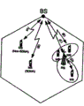
Fig. 3 is illustrated in the example that a district's band in the residential quarter uses;
Fig. 4 illustrates single residential quarter double bounce wireless communication system;
Fig. 5 illustrates the application of relay station; And
Fig. 6 illustrates the single-hop tdd frame structure for the OFDMA physical layer modes of IEEE802.16 standard.
Embodiment
Embodiments of the present invention are provided for the frame structure of multi-hop communication system, and this frame structure is the expansion of the tdd frame structure of standard.As in this manual after a while as described in, the frame structure that proposes has a lot of benefits.
The details of frame structure and system works
The frame structure that proposes designs for following situation, that is, all slave nodes that can be worked in network from the control information of the head node of controlling overall medium access receive.In addition, design by this way, that is, do not work so that do not understand leaving in the system that (legacy) single-hop TDD mobile device can enable at new relaying of relay station.
If can not receive control information from head node (perhaps source device), then need the extra frame period to be used for the double bounce transmission.This is can not be received by destination device in same frame because of the control information that is sent to intermediate equipment by source device.Destination device (especially legacy devices) will be designed to: the beginning at frame receives this control information, therefore, for intermediate equipment, need the extra frame period, with the beginning (in lead code) at frame control information is sent to and also then send data on this source.Therefore, causing is frame stand-by period of 1.
Preferred frame structure shown in Fig. 1.
It consists of by being used for the two a plurality of sending and receivings district band of down link and uplink sub-frames.These district's belt types are:
The broadcasting of the information (for example: the structure of synchronizing sequence, order, frame or the information of layout and details) that B is relevant with control.
C transmits the dedicated control information of (that is, to single receiver or one group of receiver) transmission in district's band in non-broadcasting, its
T private subscribers data (transmission) transmission
The different district's band of shown in Fig. 19 has been described in table 1.
| District's reel number | Mark | Describe |
| 1 | P | Be used for lead code or the synchronizing sequence transmission of |
| 2 | MAP | Frame format is described (district is with border, distribution etc. in district's band) |
| 3 | BS-RS/BS-MS | The transmission range band of BS to RS.If the support space division multiple access then can also be used for the transmission (that is, can come and more than one entity communication with same transmission resource) of BS to MS |
| 4 | BS-MS | The transmission range band of BS to MS, RS are inactive in this period, and RS is just processing any information that receives and turning to before transmission. |
| 5 | BS-MS/RS-MS | The transmission range band of RS to MS.Also can by BS be used for to the level that do not experience serious, send with the MS of the interference of RS transmission. |
| 6 | MS-BS/MS-RS | MS control information transmission range band.Information can be received by RS and BS.Control information can be from the information of MS or request. |
| 7 | MS-BS/MS-RS | The transmission range band of MS or RS to RS.Can be used for sending to BS with the MS that RS occurs to disturb yet. |
| 8 | MS-BS | The transmission range band of MS to BS.RS sent inactively or receives within this period; Before turning to, RS is just processing any information that receives. |
| 9 | RS-BS/MS-BS | The transmission range band of RS to BS.If the support space division multiple access then can also be used for the transmission (that is, can use same transfer resource and entity more than one to communicate) of MS to BS. |
The description of table 1. district band.
Fig. 2 shows the preferred operations of BS, RS and MS according to the BS described in table 1, RS and the activity of MS in each district's band.
Fig. 3 represents with regard to how different user types distributed to transmission in various district's belt types or reception and a specific implementation of the frame structure that proposes.
In this case, there are as described in Figure 3 five kinds of Linktypes that are designated as (A-E).In table 2, provide the description to the district's band that uses in this embodiment.
| Link | DL district band uses | UL district band uses | Note |
| (A) | (1), (2), (5) | (6), (7) | MS spatially separates with RS, thereby has obvious interference and insulation.The user does not support SDMA. |
| (B) | (1), (2), (3) | (6), (9) | MS spatially separates with RS, thereby has obvious interference and insulation.User support SDMA. |
| (C) | (1), (2), (3) (5) | (6), (7), (9) | RS1 is receive data in (3) and (7), then sends in (5) and (9), thereby can carry out relaying in the frame. |
| (D) | (1), (2), (5) | (6), (7) | MS communicates by letter with BS via RS, occurs in the beginning of UL subframe (7) to the transmission of RS, to allow the enough RS relay process time. |
| (E) | (1), (2), (4) | (6), (8) | Use district's band (4) and (8) with the MS of BS (this BS and RS do not have isolation) direct communication, disturb the infringement link performance to prevent RS. |
The description of the embodiment that the district band of table 2. pair in a residential quarter uses.
One of key advantage of the frame structure that the employing embodiment of the present invention proposes is that BS can utilize BS and the MS that all transfer resources come and network is interior to communicate always.This transfer resource that is the link by the RS to MS that reuses in the communication that is used for BS to MS uses is realized.In order to realize this mode and to prevent that this method for reusing from causing extra interference, BS must guarantee that the user who communicates by letter with this BS isolates fully with the user who just communicates by letter with RS in this reuse region band.Therefore, the BS user that necessarily requires a kind of mechanism to decide to communicate by letter with this BS should be in that (i.e. district's band (5) and (9)) still is in (that is, the district is with (4) and (8)) in the normal district band in this reuse region band.
A lot of algorithms that existence can envision form this mechanism, and the below has listed some algorithms:
1, require MS to the reuse region band during and the BS transmission during normal district band carry out carrier wave interference plus noise (CINR) measured.If CINR is higher at normal district band, then user assignment is given normal district band.If CINR is similar, then with user assignment to the reuse region band.
2, in normal district band, begin with all users.If normal district band becomes fully loaded and do not exist so that can not hold more user in new user and the existing user situation with the risk of the lowering service quality of experience, then identification will move on to from normal district band the candidate user of reuse region band.Be lower than specific threshold value if the CINR that reports for the user who communicates by letter with BS subsequently is reduced in the reuse region band, then move on to normal district band from this district's band.
The summary of advantage
Generally speaking, the advantage of embodiment of the present invention is:
Zero makes it possible to make up and move simply cheaply repeater, and this repeater does not need to generate any control information or operation dispatching;
Zero by guarantee BS at one's leisure in frame without any the time, make spectrum efficiency maximization;
Zero by making the double bounce relaying can make the stand-by period reach minimum in a frame;
Zero makes this system provide potentially transparent operation to the single-hop TDD user who leaves over;
Zero can improve spectrum efficiency further by using the technology based on SDMA, so that the identical transfer resource (frequency and time) of use between RS that can be in BS and residential quarter and the MS;
Zero provides a kind of mechanism so that BS can reuse RS-MS comunication area band with the MS direct communication, can not cause the reduction of RS-MS link performance by carrying out this communication.
Embodiments of the present invention can realize in hardware or be embodied as the software module of moving at one or more processor or be embodied as their combination.That is to say, those skilled in the art will recognize that in the function that can use in practice microprocessor or digital signal processor (DSP) to realize implementation transmitter of the present invention some or all.The present invention can also be embodied as for part or all one or more device or the device program (for example, computer program and computer program) of carrying out method as herein described.Implementing this program of the present invention and can be stored in the computer-readable medium, perhaps, for example, can be the form with one or more signal.Sort signal can be perhaps to be arranged on the carrier signal from the data-signal of internet site download, or any other form.
The present invention relates to a kind of transmission method for the double bounce wireless communication system, this system comprises source device, destination device and intermediate equipment, described source device can be used to send information along two links that form communication path, described communication path extends to described destination device from described source device via described intermediate equipment, and described intermediate equipment can be used to receive information and the information that receives is sent to described destination device from described source device along described path, described system distributes the time-frequency form of available transmission frequency bandwidth to have access right during discrete transmission intercal to being used for, described form limits a plurality of transmission windows in this interval, each window takies the different piece at described interval, and the part shared with respect to this window at described interval has the frequency bandwidth configuration in described available transmission frequency bandwidth, for this transmission intercal, each described window can be distributed to described source device or described destination device to transmit, this transmission method may further comprise the steps: utilize described form that information is sent by link ground along described path as two continuous transmitted signals, described signal uses the different transmission windows of specific this transmission intercal to send.
The above-mentioned transmission method according to the present invention, the frequency bandwidth configuration of at least two transmission windows in the described transmission window comprises the public part of described available transmission frequency bandwidth.
The above-mentioned transmission method according to the present invention, wherein, the described frequency bandwidth of described at least two described transmission windows is configured on the roughly whole transmission frequency bandwidth of separately compartment to be expanded.
The above-mentioned transmission method according to the present invention, described transmission method is further comprising the steps of: before described transmission, utilize described form that the specific transmission window of described specific transmission intercal is distributed to described source device, so that described information is sent to described intermediate equipment, and the transmission window subsequently of described specific transmission intercal is distributed to described intermediate equipment, to give described destination device with described communication.
The above-mentioned transmission method according to the present invention, described transmission method is further comprising the steps of: utilize described form that the control window is distributed to described source device, control information is transferred to described intermediate equipment.
The above-mentioned transmission method according to the present invention, wherein, described control window take described specific transmission intercal, the part before the part that is taken by described specific transmission window of described specific transmission intercal.
The above-mentioned transmission method according to the present invention, wherein, the described specific transmission window of described specific transmission intercal and described subsequently transmission window are in time in the both sides of another transmission window at described interval.
The above-mentioned transmission method according to the present invention, described transmission method is further comprising the steps of: during the part corresponding with described another transmission window of described specific transmission intercal, in described intermediate equipment, carry out to process, in order to make up the information of transmitting at described transmission window subsequently based on the information that in described specific transmission window, receives.
The above-mentioned transmission method according to the present invention, wherein, described communication path is communication path indirectly, and described system comprises at least one other destination device, and described source device can be used to along the corresponding single link that forms direct communication path information directly be sent to described other destination device or each described other destination device.
The above-mentioned transmission method according to the present invention, described transmission method is further comprising the steps of: utilize described another transmission window that information is sent to described other destination device from described source device along described direct communication path, so that carry out sending described information from described source device in the process of described processing in described intermediate equipment.
The above-mentioned transmission method according to the present invention, described transmission method may further comprise the steps: utilize described specific transmission window that information is sent to described other destination device from described source device along this direct communication path, so that during the part corresponding with described specific transmission window of described specific transmission intercal, with described information from described source device send to described intermediate equipment and described other destination device the two.
The above-mentioned transmission method according to the present invention, described transmission method may further comprise the steps: utilize described transmission window subsequently that information is sent to described other destination device from described source device along this direct communication path, so that during the part corresponding with described transmission window subsequently of described transmission intercal subsequently, information is sent to described destination device and sends to described other destination device from described source device from described intermediate equipment.
The above-mentioned transmission method according to the present invention, wherein, described communication path is communication path indirectly, and wherein said system comprises at least one other source device, and wherein said other source device or each described other source device can be used to information is directly sent to described destination device along the corresponding single link that forms direct communication path.
The above-mentioned transmission method according to the present invention, described transmission method may further comprise the steps: utilize described another transmission window that information is sent to described destination device from described other source device along this direct communication path, so that in described intermediate equipment, carry out in the process of described processing, send described information from described other source device.
The above-mentioned transmission method according to the present invention, described transmission method may further comprise the steps: utilize described specific transmission window that information is sent to described destination device from described other source device along this direct communication path, so that during the part corresponding with described specific transmission window of specific transmission intercal, described information is sent to described intermediate equipment and sends to described other destination device from described other source device from described source device.
The transmission method above-mentioned according to claim the present invention, described transmission method may further comprise the steps: utilize described transmission window subsequently that information is sent to described destination device from described other source device along this direct communication path, so that during the part corresponding with described transmission window subsequently of subsequently transmission intercal, described information is sent to described destination device and sends to described destination device from described other source device from described intermediate equipment.
The above-mentioned transmission method according to the present invention, described transmission method may further comprise the steps: utilize space division multiple access technique in one or more described transmission window of described specific transmission intercal.
The above-mentioned transmission method according to the present invention, wherein, described time-frequency form is for the form of the downlink subframe of tdd communication systems or the form of uplink sub-frames.
The above-mentioned transmission method according to the present invention, wherein, described system is OFDM or OFDMA system, and described time-frequency form is for the OFDM of OFDM or OFDMA time division duplex frame or the form of OFDMA downlink subframe or the form of uplink sub-frames.
The above-mentioned transmission method according to the present invention, wherein, each described discrete transmission intercal all is period of sub-frame.
The above-mentioned transmission method according to the present invention, wherein, each described transmission window includes the zone in OFDM or the OFDMA frame structure.
The above-mentioned transmission method according to the present invention, wherein, each described transmission window includes the district's band in OFDM or the OFDMA frame structure.
The above-mentioned transmission method according to the present invention, wherein, described source device or each described source device are the base stations.
The above-mentioned transmission method according to the present invention, wherein, described source device or each described source device are user terminals.
The above-mentioned transmission method according to the present invention, wherein, described destination device or each described destination device are the base stations.
The above-mentioned transmission method according to the present invention, wherein, described destination device or each described destination device are user terminals.
The above-mentioned transmission method according to the present invention, wherein, described intermediate equipment or each described intermediate equipment are relay stations.
According to a further aspect in the invention, a kind of transmission method for the double bounce wireless communication system also is provided, this system comprises source device, destination device and intermediate equipment, described source device can be used to send information along two links that form communication path, described communication path extends to described destination device from described source device via described intermediate equipment, and described intermediate equipment can be used to receive information and the information that receives is sent to described destination device from described source device, described system distributes the time-frequency form of available transmission frequency bandwidth to have access right during discrete transmission intercal to being used for, described form limits a plurality of transmission windows in this interval, each window takies the different piece at described interval, and the part shared with respect to this window at described interval has the frequency bandwidth configuration in described available transmission frequency bandwidth, for this transmission intercal, each described window can be distributed to described source device or described destination device to transmit, said method comprising the steps of: utilize described form that data and control information are sent along the link from described source device to described intermediate equipment together as signal transmission, and data message is sent along the link from described intermediate equipment to described destination device as signal transmission, and described signal is to use the transmission window separately of two this transmission intercals to send.
The invention still further relates to a kind of double bounce wireless communication system, this system comprises: source device, destination device and intermediate equipment, described source device can be used to send information along two links that form communication path, described communication path extends to described destination device from described source device via described intermediate equipment, and described intermediate equipment can be used to receive information and the information that receives is sent to described destination device from described source device; The form access means, it can be used to access the time-frequency form for distribute the available transmission frequency bandwidth during discrete transmission intercal, described form limits a plurality of transmission windows in this interval, each window takies the different piece at described interval, and the part shared with respect to this window at described interval has the frequency bandwidth configuration in described available transmission frequency bandwidth, for this transmission intercal, each described window can be distributed to described source device or described destination device to transmit; And transmitting device, it can be used to utilize described form, comes by the different transmission windows that use specific this transmission intercal information to be sent by link ground along relay route as two continuous signal transmissions.
According to another aspect of the present invention, one group of computer program also is provided, when this computer program makes this system carry out a kind of transmission method when the calculation element of double bounce wireless communication system moves, described system comprises source device, destination device and intermediate equipment, described source device can be used to send information along two links that form communication path, described communication path extends to described destination device from described source device via described intermediate equipment, and described intermediate equipment can be used to receive information and the information that receives is sent to described destination device from described source device, described system distributes the time-frequency form of available transmission frequency bandwidth to have access right during discrete transmission intercal to being used for, described form limits a plurality of transmission windows in this interval, each window takies the different piece at described interval, and the part shared with respect to this window at described interval has the frequency bandwidth configuration in described available transmission frequency bandwidth, for this transmission intercal, each described window can be distributed to described source device or described intermediate equipment to transmit, described transmission method may further comprise the steps: utilize described form that information is sent by link ground along relay route as two continuous signal transmissions, described signal is to use the different transmission windows of specific this transmission intercal to send.
According to a further aspect in the invention, a kind of intermediate equipment for the double bounce wireless communication system also is provided, this system also comprises source device and destination device, described source device can be used to send information along a series of links that form communication path, described communication path extends to described destination device from described source device via described intermediate equipment, and, described intermediate equipment can be used to from sending to equipment subsequently along described path along the previous equipment receiving information in described path and with the information that receives, described intermediate equipment comprises: the form access means, it can be used to access the time-frequency form for distribute the available transmission frequency bandwidth in discrete transmission intercal, described form limits a plurality of transmission windows in this interval, each window takies the different piece at described interval, and the part shared with respect to this window at described interval has the frequency bandwidth configuration in described available transmission frequency bandwidth, for this transmission intercal, each described window can be distributed to described source device or described intermediate equipment to transmit; And sender device, it can utilize for the described form of this transmission intercal available transmission window reception information at described interval, and, in available transmission window subsequently, sending described information during the same described transmission intercal, so that described information transmits along described two links in single transmission intercal.
According to a further aspect in the invention, a kind of transmission method of the intermediate equipment for the double bounce wireless communication system also is provided, this system also comprises source device and destination device, described source device can be used to send information along two links that form communication path, described communication path extends to described destination device from described source device via described intermediate equipment, and described intermediate equipment can be used to receive information and the information that receives is sent to described destination device from described source device, described intermediate equipment distributes the time-frequency form of available transmission frequency bandwidth to have access right during discrete transmission intercal to being used for, described form limits a plurality of transmission windows in this interval, each window takies the different piece at described interval, and the part shared with respect to this window at described interval has the frequency bandwidth configuration in described available transmission frequency bandwidth, for this transmission intercal, each described window can be distributed to described source device or described intermediate equipment to transmit, described transmission method may further comprise the steps: utilization is used for the described form of a this transmission method in the available transmission window reception information at described interval, and in available transmission window subsequently, sending described information during the same described transmission intercal, so that described information transmits along described two links in single transmission intercal.
According to a further aspect in the invention, a kind of computer program also is provided, when moving, the calculation element of the intermediate equipment of this computer program in the double bounce wireless communication system make this intermediate equipment carry out a kind of transmission method, this system also comprises source device and destination device, described source device can be used to send information along two links that form communication path, described communication path extends to described destination device from described source device via described intermediate equipment, and described intermediate equipment can be used to receive information and the information that receives is sent to described destination device from described source device, described system distributes the time-frequency form of available transmission frequency bandwidth to have access right during discrete transmission intercal to being used for, described form limits a plurality of transmission windows in this interval, each window takies the different piece at described interval, and the part shared with respect to this window at described interval has the frequency bandwidth configuration in described available transmission frequency bandwidth, for this transmission intercal, each described window can be distributed to described source device or described intermediate equipment to transmit, described transmission method may further comprise the steps: utilization is used for the described form of a this transmission method in the available transmission window reception information at described interval, and in a rear available transmission window, sending described information during the same described transmission intercal, so that described information transmits along described two links in single transmission intercal.
Claims (15)
1. transmission method that is used for multi-hop wireless communication system, this multi-hop wireless communication system comprises base station, relay station and mobile radio station, said method comprising the steps of:
Utilize downlink transmission frames to send, this downlink transmission frames has for the first district band that sends radio signal from described base station to described relay station, be used for sending the Second Region band of radio signal from described relay station to mobile radio station and be arranged on being used for from described base station directly between described the first district band and the described Second Region band is with to the 3rd district of mobile radio station transmission radio signal
Wherein, the described Second Region band of described downlink transmission frames also is used for the transmission from described base station to mobile radio station.
2. transmission method according to claim 1, wherein, time of providing described relay station to switch between sending mode and receiving mode is provided described the 3rd district band.
3. transmission method according to claim 1, wherein, described downlink transmission frames comprises the information of the form of having described described downlink transmission frames, and this information shows the border between described the first district band, described Second Region band and described the 3rd district band.
4. according to any one described transmission method in the aforementioned claim, wherein, if support SDMA, then described the first district band of described downlink transmission frames also is used for the transmission from described base station to mobile radio station.
5. transmission method that is used for multi-hop wireless communication system, this multi-hop wireless communication system comprises base station, relay station and mobile radio station, said method comprising the steps of:
Utilize up-link transmission frame to send, this up-link transmission frame has for the first district band that sends radio signal from mobile radio station to described relay station, is used for the Second Region band from described relay station to described base station transmission radio signal and is arranged on the 3rd district band that is used for sending to described base station from mobile radio station radio signal between described the first district band and the described Second Region band
Wherein, described the first district band of described up-link transmission frame also is used for the transmission from mobile radio station to described base station.
6. transmission method according to claim 5, wherein, time of providing described relay station to switch between sending mode and receiving mode is provided described the 3rd district band.
7. according to claim 5 or 6 described transmission methods, wherein, if support SDMA, then the described Second Region band of described up-link transmission frame also is used for the transmission from mobile radio station to described base station.
8. multi-hop wireless communication system that comprises base station, relay station and mobile radio station, this multi-hop wireless communication system comprises:
Be used for utilizing the first district band in the downlink transmission frames from described base station to described relay station transmission radio signal and utilize Second Region band in the described downlink transmission frames to send the device of radio signal from described base station to mobile radio station;
Be used for utilizing described Second Region band to send the device of radio signal from described relay station to mobile radio station;
Be used for utilizing the 3rd district that is arranged between described the first district band and the described Second Region band in the described downlink transmission frames to be with the device that directly sends radio signal from described base station to mobile radio station; And
Be used for utilizing described the 3rd district band described relay station to be switched to the device of sending mode from receiving mode.
9. multi-hop wireless communication system that comprises base station, relay station and mobile radio station, this multi-hop wireless communication system comprises:
Be used for utilizing the first district band in the up-link transmission frame to send the device of radio signal to described relay station from mobile radio station, and be used for utilizing described the first district band to send the device of radio signal to described base station from mobile radio station;
Be used for utilizing the device of Second Region band from described relay station to described base station transmission radio signal in the described up-link transmission frame;
Be used for utilizing the 3rd district that is arranged between described the first district band and the described Second Region band in the described up-link transmission frame to be with the device that directly sends radio signal from mobile radio station to described base station; And
Be used for utilizing described the 3rd district band described relay station to be switched to the device of sending mode from receiving mode.
10. the base station in the multi-hop wireless communication system, this multi-hop wireless communication system comprises this base station, relay station and mobile radio station, this base station comprises:
Be used for utilizing the first district in the downlink transmission frames to be with the device that sends radio signal to described relay station;
Be used for utilizing the interior Second Region band of described downlink transmission frames directly to send the device of radio signal to mobile radio station, wherein, described Second Region band also is used for the transmission from described relay station to mobile radio station; And
Be used for utilizing the 3rd district that is arranged between described the first district band and the described Second Region band in the described downlink transmission frames to be with the device that directly sends radio signal to mobile radio station, wherein, described relay station utilizes described the 3rd district band to switch to sending mode from receiving mode.
11. the base station in the multi-hop wireless communication system, this multi-hop wireless communication system comprises this base station, relay station and mobile radio station, and this base station comprises:
The device that is used for utilizing the first district band in the up-link transmission frame directly to receive radio signals from mobile radio station, wherein, this first district band also is used for the transmission from mobile radio station to described relay station;
For the device that utilizes the interior Second Region band of described up-link transmission frame to receive radio signals from described relay station; And
Be used for utilizing the device that the 3rd district band between described the first district band and the described Second Region band directly receives radio signals from mobile radio station that is arranged in the described up-link transmission frame, wherein, described relay station utilizes described the 3rd district band to switch to sending mode from receiving mode.
12. the relay station in the multi-hop wireless communication system, this multi-hop wireless communication system comprises base station, described relay station and mobile radio station, and this relay station comprises:
The device that is used for utilizing the first district band in the downlink transmission frames to receive radio signals from described base station;
Be used for utilizing the interior Second Region band of described downlink transmission frames to send the device of radio signal to mobile radio station, this Second Region band also is used for the transmission from described base station to mobile radio station;
Be used for utilizing the 3rd district that is arranged between described the first district band and the described Second Region band in the described downlink transmission frames to be with the device that switches to sending mode from receiving mode, described the 3rd district band also is used for described base station and sends radio signal to mobile radio station.
13. the relay station in the multi-hop wireless communication system, this multi-hop wireless communication system comprises base station, described relay station and mobile radio station, and this relay station comprises:
The device that is used for utilizing the first district band in the up-link transmission frame to receive radio signals from mobile radio station, this first district band also is used for the transmission from mobile radio station to described base station;
Be used for utilizing the interior Second Region band of described up-link transmission frame to send the device of radio signal to described base station;
Be used for utilizing the 3rd district that is arranged between described the first district band and the described Second Region band in the described up-link transmission frame to be with the device that switches to sending mode from receiving mode, described the 3rd district band also is used for mobile radio station and sends radio signal to described base station.
14. the mobile radio station in the multi-hop wireless communication system, this multi-hop wireless communication system comprises base station, relay station and a plurality of mobile radio station, and this mobile radio station comprises:
The device that is used for utilizing the first district band in the downlink transmission frames to receive radio signals from described base station, this first district band also is used for the transmission from described base station to described relay station;
For the device that the Second Region band that utilizes in the described downlink transmission frames receives radio signals from described relay station, this Second Region band also is used for the transmission from described base station to mobile radio station;
Be used for utilizing the 3rd district that is arranged between described the first district band and the described Second Region band to be with the device that receives radio signals from described base station, wherein, described relay station utilizes described the 3rd district band to switch to sending mode from receiving mode.
15. the mobile radio station in the multi-hop wireless communication system, this multi-hop wireless communication system comprises base station, relay station and a plurality of mobile radio station, and this mobile radio station also comprises:
Be used for utilizing the first district in the up-link transmission frame to be with the device that sends radio signal to described relay station, this first district band also is used for the transmission from mobile radio station to described base station;
Be used for utilizing the interior Second Region band of described up-link transmission frame to send the device of radio signal to described base station;
Be used for utilizing the 3rd district that is arranged between described the first district band and the described Second Region band in the described up-link transmission frame to be with the device that sends radio signal to described base station, wherein, described relay station utilizes described the 3rd district band to switch to sending mode from receiving mode.
Applications Claiming Priority (2)
| Application Number | Priority Date | Filing Date | Title |
|---|---|---|---|
| GB0616477.6 | 2006-08-18 | ||
| GB0616477A GB2440982A (en) | 2006-08-18 | 2006-08-18 | Wireless multi-hop communication system |
Related Parent Applications (1)
| Application Number | Title | Priority Date | Filing Date |
|---|---|---|---|
| CNA2007101419864A Division CN101127558A (en) | 2006-08-18 | 2007-08-17 | Communication systems |
Publications (2)
| Publication Number | Publication Date |
|---|---|
| CN101820311A CN101820311A (en) | 2010-09-01 |
| CN101820311B true CN101820311B (en) | 2013-04-24 |
Family
ID=37081239
Family Applications (2)
| Application Number | Title | Priority Date | Filing Date |
|---|---|---|---|
| CNA2007101419864A Pending CN101127558A (en) | 2006-08-18 | 2007-08-17 | Communication systems |
| CN2010101222646A Expired - Fee Related CN101820311B (en) | 2006-08-18 | 2007-08-17 | Multi-hop wireless communication system and transmission method therefor |
Family Applications Before (1)
| Application Number | Title | Priority Date | Filing Date |
|---|---|---|---|
| CNA2007101419864A Pending CN101127558A (en) | 2006-08-18 | 2007-08-17 | Communication systems |
Country Status (7)
| Country | Link |
|---|---|
| US (2) | US9356807B2 (en) |
| EP (2) | EP1890416B1 (en) |
| JP (2) | JP4992606B2 (en) |
| KR (2) | KR100996034B1 (en) |
| CN (2) | CN101127558A (en) |
| GB (1) | GB2440982A (en) |
| TW (2) | TW201029362A (en) |
Families Citing this family (23)
| Publication number | Priority date | Publication date | Assignee | Title |
|---|---|---|---|---|
| EP1734667B1 (en) | 2005-06-17 | 2011-08-10 | Fujitsu Limited | Multi-hop communication system |
| EP1734665B1 (en) | 2005-06-17 | 2011-08-10 | Fujitsu Limited | Multi-hop communication system |
| DE602005009340D1 (en) | 2005-06-17 | 2008-10-09 | Fujitsu Ltd | Power control in the multi-way communication system |
| EP1734666A1 (en) | 2005-06-17 | 2006-12-20 | Fujitsu Limited | Resource management in multi-hop communication system |
| GB0616476D0 (en) | 2006-08-18 | 2006-09-27 | Fujitsu Ltd | Communication systems |
| TW201028024A (en) * | 2006-08-18 | 2010-07-16 | Fujitsu Ltd | Communication systems |
| GB2440986A (en) * | 2006-08-18 | 2008-02-20 | Fujitsu Ltd | Wireless multi-hop communication system |
| GB2440981A (en) * | 2006-08-18 | 2008-02-20 | Fujitsu Ltd | Wireless multi-hop communication system |
| GB2441574A (en) * | 2006-09-08 | 2008-03-12 | Fujitsu Ltd | Network entry to a multi-hop wireless communication system |
| GB0619454D0 (en) | 2006-10-02 | 2006-11-08 | Fujitsu Ltd | Communication systems |
| GB0619455D0 (en) | 2006-10-02 | 2006-11-08 | Fujitsu Ltd | Communication system |
| GB2443464A (en) | 2006-11-06 | 2008-05-07 | Fujitsu Ltd | Signalling in a multi-hop communication systems |
| GB2447883A (en) | 2007-03-02 | 2008-10-01 | Fujitsu Ltd | Bandwidth allocation in multi-hop wireless communication systems |
| GB2447635A (en) | 2007-03-19 | 2008-09-24 | Fujitsu Ltd | Scheduling qos communications between nodes within a predetermined time unit in wimax systems |
| EP2106074B1 (en) * | 2008-03-27 | 2010-09-22 | Fujitsu Limited | Wireless communication systems |
| EP2157820A1 (en) | 2008-08-22 | 2010-02-24 | Fujitsu Limited | Methods and apparatus for operating a wireless communications system |
| US8059622B2 (en) * | 2008-09-04 | 2011-11-15 | Intel Corporation | Multi-radio platform and method for coordinating activities between a broadband wireless access network transceiver and co-located transceiver |
| KR101668704B1 (en) * | 2008-09-05 | 2016-10-28 | 엘지전자 주식회사 | Downlink silent period for positioning |
| CN101521922B (en) * | 2009-03-25 | 2012-11-07 | 华为技术有限公司 | Multiplexing area switching method and server |
| KR101877754B1 (en) | 2012-11-26 | 2018-07-13 | 삼성전자주식회사 | Communication method for transmitting and receiving channel information in a multi-hop network and terminals thereof |
| CN104053236B (en) * | 2013-03-11 | 2018-11-06 | 中兴通讯股份有限公司 | A kind of resource allocation methods, access point and relay access point |
| US11405924B2 (en) * | 2017-12-08 | 2022-08-02 | Mediatek Singapore Pte. Ltd. | Communication interference mitigation systems and methods |
| CN111356201B (en) * | 2018-12-20 | 2022-04-15 | 大唐移动通信设备有限公司 | Method and device for grouping great coverage and network node |
Citations (2)
| Publication number | Priority date | Publication date | Assignee | Title |
|---|---|---|---|---|
| CN1242561C (en) * | 1997-05-01 | 2006-02-15 | 美国电报电话公司 | Multi-jump communication system |
| CN1750494A (en) * | 2004-09-13 | 2006-03-22 | 日本电气株式会社 | Via node is installed system of selection, mounting points choice device, mounted base station |
Family Cites Families (59)
| Publication number | Priority date | Publication date | Assignee | Title |
|---|---|---|---|---|
| DE3403715A1 (en) | 1984-02-03 | 1985-08-08 | Licentia Patent-Verwaltungs-Gmbh, 6000 Frankfurt | DIGITAL CELL RADIO SYSTEM WITH TIME MULTIPLEX |
| JPH0530000A (en) * | 1991-07-18 | 1993-02-05 | Fujitsu Ltd | Mobile body communication system |
| EP0566551B1 (en) * | 1992-04-17 | 1999-08-04 | Telefonaktiebolaget L M Ericsson | Mobile assisted handover using CDMA |
| JP2661533B2 (en) * | 1993-12-27 | 1997-10-08 | 日本電気株式会社 | Channel allocation method for mobile communication system |
| US5719868A (en) * | 1995-10-05 | 1998-02-17 | Rockwell International | Dynamic distributed, multi-channel time division multiple access slot assignment method for a network of nodes |
| US6049593A (en) * | 1997-01-17 | 2000-04-11 | Acampora; Anthony | Hybrid universal broadband telecommunications using small radio cells interconnected by free-space optical links |
| EP0926905B1 (en) * | 1997-06-16 | 2010-08-11 | Mitsubishi Denki Kabushiki Kaisha | Mobile communication system |
| US6236647B1 (en) | 1998-02-24 | 2001-05-22 | Tantivy Communications, Inc. | Dynamic frame size adjustment and selective reject on a multi-link channel to improve effective throughput and bit error rate |
| DE69938979D1 (en) * | 1998-04-23 | 2008-08-07 | Mitsubishi Electric Corp | System and transmitter used in a mobile radio communication system for monitoring frequencies in another system |
| JP2954570B1 (en) | 1998-06-02 | 1999-09-27 | 株式会社次世代デジタルテレビジョン放送システム研究所 | Frequency selective interference correction device |
| US6370384B1 (en) * | 1998-07-30 | 2002-04-09 | Airnet Communications Corporation | Frequency re-use planning for wireless communications system using wireless translating repeaters |
| KR100272431B1 (en) * | 1998-09-03 | 2000-11-15 | 김영환 | Device for expanding coverage of cdma mobile communication system and method thereof |
| US7006530B2 (en) * | 2000-12-22 | 2006-02-28 | Wi-Lan, Inc. | Method and system for adaptively obtaining bandwidth allocation requests |
| US7158784B1 (en) | 2000-03-31 | 2007-01-02 | Aperto Networks, Inc. | Robust topology wireless communication using broadband access points |
| US6701129B1 (en) * | 2000-09-27 | 2004-03-02 | Nortel Networks Limited | Receiver based adaptive modulation scheme |
| US6961368B2 (en) * | 2001-01-26 | 2005-11-01 | Ericsson Inc. | Adaptive antenna optimization network |
| US7047016B2 (en) * | 2001-05-16 | 2006-05-16 | Qualcomm, Incorporated | Method and apparatus for allocating uplink resources in a multiple-input multiple-output (MIMO) communication system |
| DE60117202D1 (en) * | 2001-09-03 | 2006-04-20 | St Microelectronics Nv | A method and apparatus for estimating the speed of a mobile terminal in a wireless communication system |
| CA2415132C (en) * | 2001-12-28 | 2007-07-03 | Ntt Docomo, Inc. | Radio communication system, base station, relay station, mobile station, and packet transmission control method |
| US20030129982A1 (en) * | 2002-01-04 | 2003-07-10 | Patrick Perini | Soft handoff in a wireless communication system |
| GB0200237D0 (en) | 2002-01-07 | 2002-02-20 | Imec Inter Uni Micro Electr | Wireless cellular network architecture |
| US7096274B1 (en) | 2002-02-12 | 2006-08-22 | 3Com Corporation | Optimum frame size predictor for wireless Local Area Network |
| KR100509687B1 (en) * | 2002-02-15 | 2005-08-23 | 주식회사 위다스 | Apparatus for testing isolation status in RF repeater and method thereof |
| JP2004040568A (en) * | 2002-07-04 | 2004-02-05 | Denso Corp | Radio communications terminal |
| US7580394B2 (en) * | 2002-11-27 | 2009-08-25 | Nokia Corporation | System and method for collision-free transmission scheduling in a network |
| US20040109428A1 (en) * | 2002-12-09 | 2004-06-10 | Srikanth Krishnamurthy | Method and apparatus for resource allocation for multiple traffic classes in wireless ad-hoc networks |
| US7583619B2 (en) * | 2002-12-16 | 2009-09-01 | Nortel Networks Limited | Wireless access communications network |
| WO2004059882A1 (en) * | 2002-12-25 | 2004-07-15 | Fujitsu Limited | Radio communication system, relay apparatus and mobile terminal |
| US20050157681A1 (en) * | 2003-02-26 | 2005-07-21 | Yoshiharu Tajima | Diversity handover method, control station and mobile terminal device in mobile communications |
| US7218891B2 (en) * | 2003-03-31 | 2007-05-15 | Nortel Networks Limited | Multi-hop intelligent relaying method and apparatus for use in a frequency division duplexing based wireless access network |
| US7027827B2 (en) * | 2003-05-19 | 2006-04-11 | Motorola, Inc. | Method and apparatus for channel sharing between multiple communication systems |
| JP4564012B2 (en) | 2003-05-28 | 2010-10-20 | テレフオンアクチーボラゲット エル エム エリクソン(パブル) | Method and system for a wireless communication network utilizing relay |
| US7313399B2 (en) * | 2003-06-05 | 2007-12-25 | Millennial Net, Inc. | Protocol for configuring a wireless network |
| US7903538B2 (en) * | 2003-08-06 | 2011-03-08 | Intel Corporation | Technique to select transmission parameters |
| US7400856B2 (en) * | 2003-09-03 | 2008-07-15 | Motorola, Inc. | Method and apparatus for relay facilitated communications |
| US7990905B2 (en) * | 2003-12-30 | 2011-08-02 | Nokia Corporation | Communication system using relay base stations with asymmetric data links |
| WO2006000091A1 (en) | 2004-06-24 | 2006-01-05 | Nortel Networks Limited | Preambles in ofdma system |
| JP2006033207A (en) | 2004-07-14 | 2006-02-02 | Nec Corp | Position information providing system, radio base station device, position information providing method used for both, and program thereof |
| US8019352B2 (en) | 2004-07-23 | 2011-09-13 | Wireless Valley Communications, Inc. | System, method, and apparatus for determining and using the position of wireless devices or infrastructure for wireless network enhancements |
| US20060029017A1 (en) * | 2004-07-26 | 2006-02-09 | Beceem Communications Inc. | Method and system for transmitting training information in a block transmission system |
| US7864659B2 (en) * | 2004-08-02 | 2011-01-04 | Interdigital Technology Corporation | Quality control scheme for multiple-input multiple-output (MIMO) orthogonal frequency division multiplexing (OFDM) systems |
| JP4494134B2 (en) * | 2004-09-01 | 2010-06-30 | Kddi株式会社 | Wireless communication system, relay station apparatus and base station apparatus |
| DE602004006624T2 (en) | 2004-09-13 | 2008-01-31 | Alcatel Lucent | Estimation of the transmission quality in a radio network |
| PT1808038E (en) * | 2004-10-20 | 2012-05-22 | T mobile int ag | Cellular wide-area radio communications system with relay-enhanced cells |
| EP1803316B1 (en) * | 2004-10-21 | 2015-03-04 | Panasonic Corporation | System and method for relaying in multi-hop cellular networks |
| KR100810290B1 (en) * | 2004-12-14 | 2008-03-07 | 삼성전자주식회사 | Method and system for allocation data burst in a wireless communication system |
| KR100584409B1 (en) | 2004-12-29 | 2006-05-26 | 삼성전자주식회사 | Relay commonication method for ofdma-based cellular communication system |
| US8644130B2 (en) | 2005-03-18 | 2014-02-04 | Samsung Electronics Co., Ltd. | System and method for subcarrier allocation in a wireless multihop relay network |
| US7486928B2 (en) * | 2005-04-14 | 2009-02-03 | Kddi Corporation | Methods and apparatus for wireless communications |
| US7813695B2 (en) | 2005-05-06 | 2010-10-12 | Telefonaktiebolaget L M Ericsson (Publ) | Mobile assisted relay selection in a telecommunications system |
| JP2006319676A (en) * | 2005-05-12 | 2006-11-24 | Oki Electric Ind Co Ltd | Frame transmitting method, topology acquiring method and radio communication system |
| KR100855225B1 (en) * | 2005-09-28 | 2008-08-29 | 삼성전자주식회사 | Apparatus and method for communicating frame data in a multi-hop relay broadband wireless access communication system |
| KR100615139B1 (en) * | 2005-10-18 | 2006-08-22 | 삼성전자주식회사 | Method and apparatus for allocating transmission period in wireless telecommunication system and therefor system |
| JP2007129726A (en) | 2005-11-04 | 2007-05-24 | Samsung Electronics Co Ltd | Apparatus and method for supporting multilink by grouping multihop in cellular network of multihop relay system |
| KR100853422B1 (en) | 2006-01-03 | 2008-08-21 | 삼성전자주식회사 | Method for requesting and allocating of upstream bandwidth in a multi-hop relay broadband wireless access communication system |
| US20070217353A1 (en) * | 2006-03-20 | 2007-09-20 | Motorola, Inc. | Method and Apparatus for Transmitting Data Within a Multi-Hop Communication System |
| GB2440984A (en) * | 2006-08-18 | 2008-02-20 | Fujitsu Ltd | Wireless multi-hop communication system |
| GB2440985A (en) * | 2006-08-18 | 2008-02-20 | Fujitsu Ltd | Wireless multi-hop communication system |
| JP5034369B2 (en) * | 2006-08-18 | 2012-09-26 | 富士通株式会社 | Wireless communication control method |
-
2006
- 2006-08-18 GB GB0616477A patent/GB2440982A/en not_active Withdrawn
-
2007
- 2007-07-31 EP EP07113531.3A patent/EP1890416B1/en not_active Expired - Fee Related
- 2007-07-31 TW TW099110353A patent/TW201029362A/en unknown
- 2007-07-31 TW TW096127955A patent/TWI356645B/en not_active IP Right Cessation
- 2007-07-31 EP EP09179735A patent/EP2178325B1/en not_active Expired - Fee Related
- 2007-08-17 CN CNA2007101419864A patent/CN101127558A/en active Pending
- 2007-08-17 CN CN2010101222646A patent/CN101820311B/en not_active Expired - Fee Related
- 2007-08-17 KR KR1020070083023A patent/KR100996034B1/en not_active IP Right Cessation
- 2007-08-17 US US11/840,570 patent/US9356807B2/en active Active
- 2007-08-20 JP JP2007214172A patent/JP4992606B2/en not_active Expired - Fee Related
-
2009
- 2009-10-22 KR KR1020090100897A patent/KR101041639B1/en not_active IP Right Cessation
-
2010
- 2010-02-05 US US12/701,191 patent/US8594009B2/en not_active Expired - Fee Related
- 2010-03-12 JP JP2010056535A patent/JP5062274B2/en not_active Expired - Fee Related
Patent Citations (2)
| Publication number | Priority date | Publication date | Assignee | Title |
|---|---|---|---|---|
| CN1242561C (en) * | 1997-05-01 | 2006-02-15 | 美国电报电话公司 | Multi-jump communication system |
| CN1750494A (en) * | 2004-09-13 | 2006-03-22 | 日本电气株式会社 | Via node is installed system of selection, mounting points choice device, mounted base station |
Non-Patent Citations (1)
| Title |
|---|
| Fang-Ching Ren et.al.Recommendation on PMP Mode Compatible TDD Frame Structure.《http://wirelessman.org/sg/mmr/contrib/C80216mmr-05_027r2.pdf》.2005,第1—16页. * |
Also Published As
| Publication number | Publication date |
|---|---|
| JP2010187386A (en) | 2010-08-26 |
| EP2178325A3 (en) | 2010-05-19 |
| CN101127558A (en) | 2008-02-20 |
| JP2008048421A (en) | 2008-02-28 |
| US20100150051A1 (en) | 2010-06-17 |
| EP2178325B1 (en) | 2012-02-22 |
| KR20100002235A (en) | 2010-01-06 |
| TW201029362A (en) | 2010-08-01 |
| GB2440982A (en) | 2008-02-20 |
| KR20080016504A (en) | 2008-02-21 |
| JP5062274B2 (en) | 2012-10-31 |
| KR100996034B1 (en) | 2010-11-22 |
| TW200816686A (en) | 2008-04-01 |
| EP1890416A2 (en) | 2008-02-20 |
| JP4992606B2 (en) | 2012-08-08 |
| EP1890416B1 (en) | 2014-01-08 |
| EP1890416A3 (en) | 2010-05-19 |
| TWI356645B (en) | 2012-01-11 |
| GB0616477D0 (en) | 2006-09-27 |
| US9356807B2 (en) | 2016-05-31 |
| KR101041639B1 (en) | 2011-06-14 |
| EP2178325A2 (en) | 2010-04-21 |
| US8594009B2 (en) | 2013-11-26 |
| US20080043816A1 (en) | 2008-02-21 |
| CN101820311A (en) | 2010-09-01 |
Similar Documents
| Publication | Publication Date | Title |
|---|---|---|
| CN101820311B (en) | Multi-hop wireless communication system and transmission method therefor | |
| CN101179326B (en) | Communication system | |
| CN101507314B (en) | Communication systems | |
| JP5035320B2 (en) | Wireless communication system, base station, relay station, user apparatus, and communication method | |
| EP1890446B1 (en) | Multi-hop wireless communication | |
| CN101127562A (en) | Communication systems | |
| CN101141809B (en) | Communication systems | |
| CN101502147A (en) | Communication systems | |
| KR100983942B1 (en) | Communication method for use in multi-hop wireless communication system, multi-hop wireless communication system, base station apparatus, intermediate apparatus, and use equipment |
Legal Events
| Date | Code | Title | Description |
|---|---|---|---|
| C06 | Publication | ||
| PB01 | Publication | ||
| C10 | Entry into substantive examination | ||
| SE01 | Entry into force of request for substantive examination | ||
| C14 | Grant of patent or utility model | ||
| GR01 | Patent grant | ||
| CF01 | Termination of patent right due to non-payment of annual fee | ||
| CF01 | Termination of patent right due to non-payment of annual fee |
Granted publication date: 20130424 Termination date: 20160817 |