EP1890377B1 - Verfahren zum Bestimmen der Rotorwinkelposition einer rotierenden elektrischen Maschine - Google Patents
Verfahren zum Bestimmen der Rotorwinkelposition einer rotierenden elektrischen Maschine Download PDFInfo
- Publication number
- EP1890377B1 EP1890377B1 EP06405343A EP06405343A EP1890377B1 EP 1890377 B1 EP1890377 B1 EP 1890377B1 EP 06405343 A EP06405343 A EP 06405343A EP 06405343 A EP06405343 A EP 06405343A EP 1890377 B1 EP1890377 B1 EP 1890377B1
- Authority
- EP
- European Patent Office
- Prior art keywords
- phase angle
- rotor
- determined
- short
- angle
- Prior art date
- Legal status (The legal status is an assumption and is not a legal conclusion. Google has not performed a legal analysis and makes no representation as to the accuracy of the status listed.)
- Not-in-force
Links
- 238000000034 method Methods 0.000 title claims abstract description 20
- 238000004804 winding Methods 0.000 claims abstract description 22
- 238000012937 correction Methods 0.000 claims abstract description 15
- 238000012544 monitoring process Methods 0.000 claims description 2
- 230000004907 flux Effects 0.000 description 6
- 230000001360 synchronised effect Effects 0.000 description 2
- 230000001419 dependent effect Effects 0.000 description 1
- 238000011161 development Methods 0.000 description 1
- 230000018109 developmental process Effects 0.000 description 1
- 238000011017 operating method Methods 0.000 description 1
Images
Classifications
-
- H—ELECTRICITY
- H02—GENERATION; CONVERSION OR DISTRIBUTION OF ELECTRIC POWER
- H02P—CONTROL OR REGULATION OF ELECTRIC MOTORS, ELECTRIC GENERATORS OR DYNAMO-ELECTRIC CONVERTERS; CONTROLLING TRANSFORMERS, REACTORS OR CHOKE COILS
- H02P6/00—Arrangements for controlling synchronous motors or other dynamo-electric motors using electronic commutation dependent on the rotor position; Electronic commutators therefor
- H02P6/14—Electronic commutators
- H02P6/16—Circuit arrangements for detecting position
- H02P6/18—Circuit arrangements for detecting position without separate position detecting elements
Definitions
- the invention relates to the field of operating methods of rotating electrical machines. It is based on a method for determining the rotor angle position or the determination of the magnetic flux angle of a rotating electrical machine according to the preamble of the independent claim.
- a rotary electric machine which is common today has a stator winding set and a rotor winding set, the stator winding set typically being fed by an associated converter unit.
- the rotor angle position of such a rotary electric machine is today mainly determined by rotary encoder, which provides the desired rotor angular position, ie the angle of the rotor during its rotation or the magnetic flux angle.
- the knowledge of the position of the rotor or the position of the magnetic flux vector is typically required for controlling the machine as one of currently several input variables.
- Encoders are very susceptible to mechanical damage Stress and therefore often fail or provide faulty rotor angle position values.
- the assembly is complicated, since the encoder itself and also the wiring must be attached to the machine, which is laborious and costly.
- such a rotary encoder must always be maintained, which means additional effort.
- a method of determining the rotor angular position of a rotary electric machine the machine having a stator winding set and a rotor winding set and in which method the stator winding set is fed by an associated inverter unit.
- the stator winding set is once short-circuited by the converter unit within one revolution of the rotor at an assumed speed of the rotor.
- the phase angle of the stator current is determined and a correction phase angle is added to the last determined phase angle.
- the object of the invention is therefore to provide a method for determining the rotor angle position of a rotating electrical machine, which is very easy to implement and robust and manages without rotary encoder. This object is solved by the features of claim 1. In the dependent claims advantageous developments of the invention are given.
- the machine has a stator winding set and a rotor winding set, the stator winding set being fed by an associated converter unit.
- the stator winding set is then short-circuited by means of the converter unit within one revolution of the rotor at an assumed speed of the rotor at at least three predeterminable short-circuit times. For each short-circuit time, the phase angle of the respective stator current is determined.
- a differential phase angle is determined at two respective temporally adjacent short circuit times (determined phase angles) and the minimum differential phase angle is calculated from the differential phase angles.
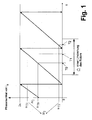
- Fig.1 a time profile of the phase angle of the stator current of the rotating electric machine is shown, which occurs in the inventive method.
- the course of the phase angle of the stator current runs according to Fig. 1 from 0 to 2 ⁇ , then starts again at 0 and runs again until 2 ⁇ and so on.
- the machine has a stator winding set and a rotor winding set, wherein the stator winding set is fed by a corresponding converter unit in terms of the method.
- the rotating electrical machine is typically designed as a synchronous machine or asynchronous machine.
- the stator winding set is now short-circuited by means of the converter unit within one revolution of the rotor at an assumed speed of the rotor at at least three predeterminable short-circuit times T0, T1, T2.
- Fig. 1 For example, a time interval is shown, which corresponds to one revolution of the rotor at an assumed speed of the rotor.
- the stator winding set is then short-circuited by means of the converter unit at the at least three predeterminable short-circuit times T0, T1, T2.
- T0, T1, T2 becomes, as in Fig.
- the phase angle ⁇ T0 , ⁇ T1 , ⁇ T2 of the respective stator current i ST0 , i ST1 , i ST2 determined.
- the respective stator current is i ST0, i ST1, i ST2 determined in particular by measuring, for example the current sensors, the amplitude î ST0, î ST1, î ST2 of the respective stator current i ST0, i ST1, i ST2 and the phase angle ⁇ T0 , ⁇ T1 , ⁇ T2 of the respective stator current i ST0 , i ST1 , i ST2 is determined.
- a differential phase angle .DELTA.i 1 , .DELTA.i 2 is formed.
- the minimum differential phase angle .DELTA.i min determined in particular by simple comparison values.
- a correction phase angle ⁇ i K is added to the last determined phase angle ⁇ T2 , and at a positive minimum difference phase angle ⁇ i min , the correction phase angle ⁇ i K is subtracted from the last determined phase angle ⁇ T2 .
- the correction phase angle ⁇ i is K ⁇ / 2.
- stator current of the rotating electrical machine generally lags the magnetic stator flux of the rotating electrical machine by ⁇ / 2, and that the direction, ie the angle, of the vector of the magnetic stator flux in the case of no load on the rotating electrical Machine corresponds to the rotor angle position (in the case of a synchronous machine) or the position of the magnetic flux vector (in the case of an asynchronous machine).
- the result after the above addition of the correction phase angle .DELTA.i K to the most recently determined phase angle ⁇ T2 or after the subtraction of the correction phase angle .DELTA.i K from the most recently determined phase angle ⁇ T2 is then searched the rotor angular position.
- the determination of the rotor angle position of the rotary electric machine according to the inventive method is therefore advantageous without encoder with all its disadvantages possible, so that a total of a very achieved easy to implement and robust method for determining the rotor angle position of a rotating electrical machine. It has proved to be advantageous that the short-circuit times T0, T1, T2 are equidistant within one revolution of the rotor at the assumed speed of the rotor.
- the amplitude î ST0 , î ST1 , î ST2 of the respective stator current î ST0 , î ST1 , i ST2 is determined for each short-circuit time T0, T1, T2.
- Each determined amplitude î ST0 , î ST1 , î ST2 is monitored within a predefinable monitoring period to an adjustable amplitude threshold .
- an overall phase difference angle ⁇ i in particular by subtraction of the determined phase angles ⁇ T0 , ⁇ T1 , ⁇ T2 , is formed from the determined phase angles ⁇ T0 , ⁇ T1 , ⁇ T2 within one revolution of the rotor.
- the total phase difference angle ⁇ i is then monitored for an adjustable total phase difference angle threshold.
- the assumed speed of the rotor is advantageously reduced when falling below the adjustable amplitude threshold or below the adjustable Bacphasendifferenzwinkelschwellives.
- the rotor angular position can then be correctly and uniquely determined according to the above-mentioned steps.
Landscapes
- Engineering & Computer Science (AREA)
- Power Engineering (AREA)
- Control Of Motors That Do Not Use Commutators (AREA)
- Control Of Ac Motors In General (AREA)
- Manufacture Of Motors, Generators (AREA)
- Motor Or Generator Frames (AREA)
- Control Of Electric Motors In General (AREA)
Description
- Die Erfindung bezieht sich auf das Gebiet der Betriebsverfahren rotierender elektrischer Maschinen. Sie geht aus von einem Verfahren zum Bestimmen der Rotorwinkelposition bzw. der Bestimmung des magnetischen Flusswinkels einer rotierenden elektrischen Maschine gemäss dem Oberbegriff des unabhängigen Anspruchs.
- Eine heute gängige rotierende elektrische Maschine weist einen Statorwicklungssatz und einen Rotorwicklungssatz auf, wobei der Statorwicklungssatz typischerweise von einer zugehörigen Umrichtereinheit gespeist wird. Die Rotorwinkelposition einer solchen rotierenden elektrischen Maschine wird heute hauptsächlich durch Drehgeber bestimmt, der die gewünschte Rotorwinkelposition, d.h. den Winkel des Rotors bei dessen Drehung bzw. den magnetischen Flusswinkel, liefert. Die Kenntnis über die Position des Rotors bzw. der Position des magnetischen Flussvektors wird typischerweise zur Regelung der Maschine als eine von gängigerweise mehreren Eingangsgrössen benötigt. Drehgeber sind aber sehr anfällig gegen mechanische Beanspruchung und fallen demnach oft aus oder liefern fehlerhafte Rotorwinkelpositionswerte. Zudem ist die Montage aufwendig, da der Drehgeber selbst und zudem die Verkabelung an der Maschine angebracht werden muss, was arbeits- und kostenintensiv ist. Ferner muss ein solcher Drehgeber stets gewartet werden, was zusätzlichen Aufwand bedeutet.
- In der
US 2002/0043953 A1 ist ein Verfahren zum Bestimmen der Rotorwinkelposition einer rotierenden elektrischen Maschine angegeben, welche Maschine einen Statorwicklungssatz und einen Rotorwicklungssatz aufweist und bei welchem Verfahren der Statorwicklungssatz von einer zugehörigen Umrichtereinheit gespeist wird. Der Statorwicklungssatz wird mittels der Umrichtereinheit innerhalb einer Umdrehung des Rotors bei einer angenommenen Geschwindigkeit des Rotors einmal kurzgeschlossen. Zu dem einmaligen Kurzschlusszeitpunkt wird der Phasenwinkel des Statorstromes ermittelt und ein Korrekturphasenwinkel zu dem zuletzt ermittelten Phasenwinkel addiert. - In der 6,281,656 B1 ist ein weiteres Verfahren zum Bestimmen der Rotorwinkelposition einer rotierenden elektrischen Maschine nach dem Stand der Technik aufgezeigt.
- Aufgabe der Erfindung ist es deshalb, ein Verfahren zum Bestimmen der Rotorwinkelposition einer rotierenden elektrischen Maschine anzugeben, welches sehr einfach realisierbar und robust ist und ohne Drehgeber auskommt. Diese Aufgabe wird durch die Merkmale des Anspruchs 1 gelöst. In den abhängigen Ansprüchen sind vorteilhafte Weiterbildungen der Erfindung angegeben.
- Beim erfindungsgemässen Verfahren zum Bestimmen der Rotorwinkelposition einer rotierenden elektrischen Maschine weist die Maschine einen Statorwicklungssatz und einen Rotorwicklungssatz auf, wobei der Statorwicklungssatz von einer zugehörigen Umrichtereinheit gespeist wird. Nach der Erfindung wird dann der Statorwicklungssatz mittels der Umrichtereinheit innerhalb einer Umdrehung des Rotors bei einer angenommenen Geschwindigkeit des Rotors an mindestens drei vorgebbaren Kurzschlusszeitpunkten kurzgeschlossen. Zu jedem Kurzschlusszeitpunkt wird der Phasenwinkel des jeweiligen Statorstromes ermittelt. Weiterhin wird aus an jeweils zwei zeitlich nächst benachbarten Kurzschlusszeitpunkten (ermittelten Phasenwinkeln ein Differenzphasenwinkel gebildet und der minimale Differenzphasenwinkel aus den Differenzphasenwinkeln ermittelt. Bei einem negativen minimalen Differenzphasenwinkel wird ein Korrekturphasenwinkel zum zuletzt ermittelten Phasenwinkel addiert und bei einem positiven minimalen Differenzphasenwinkel wird der Korrekturphasenwinkel vom zuletzt ermittelten Phasenwinkel subtrahiert. Das Ergebnis nach der Addition des Korrekturphasenwinkels beziehungsweise nach der Subtraktion des Korrekturphasenwinkels ist dann die gesuchte Rotorwinkelposition. Die Bestimmung der Rotorwinkelposition einer rotierenden elektrischen Maschine gemäss dem erfindungsgemässen Verfahren ist somit vorteilhaft ohne Drehgeber mit all seinen Nachteilen möglich, so dass insgesamt ein sehr einfach zu realisierendes und robustes Verfahren zur Bestimmung der Rotorwinkelposition einer rotierenden elektrischen Maschine erreicht ist.
- Diese und weitere Aufgaben, Vorteile und Merkmale der vorliegenden Erfindung werden aus der nachfolgenden detaillierten Beschreibung bevorzugter Ausführungsformen der Erfindung in Verbindung mit der Zeichnung offensichtlich.
- Es zeigt:
- Fig. 1
- Zeitlicher Verlauf des Phasenwinkels des Statorstromes der rotierenden elektrischen Maschine beim erfindungsgemässen Verfahren.
- Grundsätzlich sind in der Figur gleiche Teile mit gleichen Bezugszeichen versehen.
- In
Fig.1 ist ein zeitlicher Verlauf des Phasenwinkels des Statorstromes der rotierenden elektrischen Maschine dargestellt, der beim erfindungsgemässen Verfahren auftritt. Der Verlauf des Phasenwinkels des Statorstromes läuft gemässFig. 1 von 0 bis 2π, startet dann wieder bei 0 und läuft erneut bis 2π und so fort. Die Maschine weist einen Statorwicklungssatz und einen Rotorwicklungssatz auf, wobei der Statorwicklungssatz verfahrensmässig von einer zugehörigen Umrichtereinheit gespeist wird. Die rotierende elektrische Maschine ist typischerweise als Synchronmaschine oder Asynchronmaschine ausgebildet. - Beim erfindungsgemässen Verfahren wird nun der Statorwicklungssatz mittels der Umrichtereinheit innerhalb einer Umdrehung des Rotors bei einer angenommenen Geschwindigkeit des Rotors an mindestens drei vorgebbaren Kurzschlusszeitpunkten T0, T1, T2 kurzgeschlossen. In
Fig. 1 ist beispielhaft ein zeitliches Intervall eingezeichnet, welches einer Umdrehung des Rotors bei einer angenommenen Geschwindigkeit des Rotors entspricht. Innerhalb dieser Umdrehung wird dann der Statorwicklungssatz mittels der Umrichtereinheit an den mindestens drei vorgebbaren Kurzschlusszeitpunkten T0, T1, T2 kurzgeschlossen. Zu jedem Kurzschlusszeitpunkt T0, T1, T2 wird, wie inFig. 1 angedeutet, der Phasenwinkel αT0, αT1, αT2 des jeweiligen Statorstromes iST0, iST1, iST2 ermittelt. Vorzugsweise wird der jeweilige Statorstrom iST0, iST1, iST2 insbesondere durch Messung, beispielsweise über Stromsensoren, ermittelt, wobei die Amplitude îST0, îST1, îST2 des jeweiligen Statorstromes iST0, iST1, iST2 und der Phasenwinkel αT0, αT1, αT2 des jeweiligen Statorstromes iST0, iST1, iST2 ermittelt wird. Aus an jeweils zwei zeitlich nächst benachbarten Kurzschlusszeitpunkten T0, T1, T2 ermittelten Phasenwinkeln αT0, αT1, αT2 wird ein Differenzphasenwinkel Δi1, Δi2 gebildet. Die dazugehörigen Formeln lauten bei angenommenen drei Phasenwinkeln αT0, αT1, αT2 innerhalb einer Umdrehung des Rotors wie folgt:
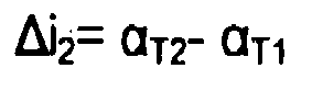
- Aus den Differenzphasenwinkeln Δi1, Δi2 wird dann ferner der minimale Differenzphasenwinkel Δimin, insbesondere durch einfachen Wertevergleich, ermittelt. Bei einem negativen minimalen Differenzphasenwinkel Δimin wird ein Korrekturphasenwinkel ΔiK zum zuletzt ermittelten Phasenwinkel αT2 addiert und bei einem positiven minimalen Differenzphasenwinkel Δimin wird der Korrekturphasenwinkel ΔiK vom zuletzt ermittelten Phasenwinkel αT2 subtrahiert. Vorzugsweise ist der der Korrekturphasenwinkel ΔiK π/2. Dabei macht man sich zu nutze, dass der Statorstrom der rotierenden elektrischen Maschine allgemein dem magnetischen Statorfluss der rotierenden elektrischen Maschine um π/2 nacheilt, und dass die Richtung, d.h. der Winkel, des Vektors des magnetischen Statorflusses im Falle keiner Last an der rotierenden elektrischen Maschine der Rotorwinkelposition (im Falle einer Synchronmaschine) oder der Position des magnetischen Flussvektors (im Falle einer Asynchronmaschine) entspricht. Das Ergebnis nach der vorstehend genannten Addition des Korrekturphasenwinkels ΔiK zum zuletzt ermittelten Phasenwinkel αT2 beziehungsweise nach der Subtraktion des Korrekturphasenwinkels ΔiK vom zuletzt ermittelten Phasenwinkel αT2 ist dann die gesuchte Rotorwinkelposition. Ob sich ein negativer minimaler Differenzphasenwinkel Δimin ergibt und demnach ein Korrekturphasenwinkel ΔiK addiert wird, oder ob sich ein positiver minimaler Differenzphasenwinkel Δimin ergibt und demnach ein Korrekturphasenwinkel ΔiK subtrahiert wird, hängt von der Drehrichtung des Rotors ab. Die Bestimmung der Rotorwinkelposition der rotierenden elektrischen Maschine gemäss dem erfindungsgemässen Verfahren ist demzufolge vorteilhaft ohne Drehgeber mit all seinen Nachteilen möglich, so dass insgesamt ein sehr einfach zu realisierendes und robustes Verfahren zur Bestimmung der Rotorwinkelposition einer rotierenden elektrischen Maschine erzielt ist.
Es hat sich als vorteilhaft erwiesen, dass die Kurzschlusszeitpunkten T0, T1, T2 innerhalb einer Umdrehung des Rotors bei der angenommenen Geschwindigkeit des Rotors äquidistant sind. - Wie bereits vorstehend erwähnt, wird zu jedem Kurzschlusszeitpunkt T0, T1, T2 die Amplitude îST0, îST1, îST2 des jeweiligen Statorstromes îST0, îST1, iST2 ermittelt. Jede ermittelte Amplitude îST0, îST1, îST2 wird innerhalb eines vorgebbaren Überwachungszeitraums auf einen einstellbaren Amplitudenschwellwert hin überwacht. Weiterhin wird aus den ermittelten Phasenwinkeln αT0, αT1, αT2 innerhalb einer Umdrehung des Rotors ein Gesamtphasendifferenzwinkel Δi, insbesondere durch Differenzbildung der ermittelten Phasenwinkel αT0, αT1, αT2, gebildet. Der Gesamtphasendifferenzwinkel Δi wird dann auf einen einstellbaren Gesamtphasendifferenzwinkelschwellwert hin überwacht. Dreht die Maschine real langsamer als die angenommene Geschwindigkeit, so zeigt sich dies durch Unterschreiten des einstellbaren Amplitudenschwellwertes oder durch Unterschreiten des einstellbaren Gesamtphasendifferenzwinkelschwellwertes. Deshalb wird die angenommene Geschwindigkeit des Rotors bei Unterschreiten des einstellbaren Amplitudenschwellwertes oder bei Unterschreiten des einstellbaren Gesamtphasendifferenzwinkelschwellwertes vorteilhaft reduziert. Mittels der Reduktion der angenommenen Geschwindigkeit des Rotors kann die Rotorwinkelposition dann wieder richtig und eindeutig gemäss den vorstehend angegebenen Schritten bestimmt werden.
Claims (4)
- Verfahren zum Bestimmen der Rotorwinkelposition einer rotierenden elektrischen Maschine, welche Maschine einen Statorwicklungssatz und einen Rotorwicklungssatz aufweist, bei dem der Statorwicklungssatz von einer zugehörigen Umrichtereinheit gespeist wird, und der Statorwicklungssatz mittels der Umrichtereinheit innerhalb einer Umdrehung des Rotors bei einer angenommenen Geschwindgkeit des Rotors kurzgeschlossen wird und zu dem Kurzschlusszeitpunkt der Phasenwinkel des Statorstroms ermittelt wird,
dadurch gekennzeichnet,
dass der Statorwicklungssatz mittels der Umrichtereinheit innerhalb einer Umdrehung des Rotors bei einer angenommenen Geschwindigkeit des Rotors an mindestens drei vorgebbaren Kurzschlusszeitpunkten (T0, T1, T2) kurzgeschlossen wird,
dass zu jedem Kurzschlusszeitpunkt (T0, T1, T2) der Phasenwinkel (T0, T1, T2) des jeweiligen Statorstromes (iST0, iST1, iST2) ermittelt wird,
dass aus an jeweils zwei zeitlich nächst benachbarten Kurzschlusszeitpunkten (T0, T1, T2) ermittelten Phasenwinkeln (T0, T1, T2) ein Differenzphasenwinkel (i1, i2) gebildet wird,
dass der minimale Differenzphasenwinkel (imin) aus den Differenzphasenwinkeln (i1, i2) ermittelt wird, und
dass bei einem negativen minimalen Differenzphasenwinkel (imin) ein Korrekturphasenwinkel (iK) zum zuletzt ermittelten Phasenwinkel (T2) addiert wird und bei einem positiven minimalen Differenzphasenwinkel (imin) der Korrekturphasenwinkel (iK) vom zuletzt ermittelten Phasenwinkel (T2) subtrahiert wird. - Verfahren nach Anspruch 1, dadurch gekennzeichnet, dass der Korrekturphasenwinkel (ΔiK) π/2 ist.
- Verfahren nach Anspruch 1 oder 2, dadurch gekennzeichnet, dass die Kurzschlusszeitpunkten (T0, T1, T2) innerhalb einer Umdrehung des Rotors bei der angenommenen Geschwindigkeit des Rotors äquidistant sind.
- Verfahren nach einem der Ansprüche 1 bis 3 , dadurch gekennzeichnet, dass zu jedem Kurzschlusszeitpunkt (T0, T1, T2) die Amplitude (îST0, îST1, îST2,) des jeweiligen Statorstromes (iST0, iST1, iST2) ermittelt wird,
dass jede ermittelte Amplitude (îST0, îST1, îST2) innerhalb eines vorgebbaren Überwachungszeitraums auf einen einstellbaren Amplitudenschwellwert hin überwacht wird, dass aus den ermittelten Phasenwinkeln (αT0, αT1, αT2) innerhalb einer Umdrehung des Rotors ein Gesamtphasendifferenzwinkel (Δi) gebildet wird,
dass der Gesamtphasendifferenzwinkel (Δi) auf einen einstellbaren Gesamtphasendifferenzwinkelschwellwert hin überwacht wird,
dass bei Unterschreiten des einstellbaren Amplitudenschwellwertes oder bei Unterschreiten des einstellbaren Gesamtphasendifferenzwinkelschwellwertes die angenommene Geschwindigkeit des Rotors reduziert wird.
Priority Applications (10)
| Application Number | Priority Date | Filing Date | Title |
|---|---|---|---|
| AT06405343T ATE502433T1 (de) | 2006-08-14 | 2006-08-14 | Verfahren zum bestimmen der rotorwinkelposition einer rotierenden elektrischen maschine |
| ES06405343T ES2362003T3 (es) | 2006-08-14 | 2006-08-14 | Procedimiento para la determinación de la posición angular del rotor de una máquina eléctrica giratoria. |
| EP06405343A EP1890377B1 (de) | 2006-08-14 | 2006-08-14 | Verfahren zum Bestimmen der Rotorwinkelposition einer rotierenden elektrischen Maschine |
| PL06405343T PL1890377T3 (pl) | 2006-08-14 | 2006-08-14 | Sposób określania położenia kątowego wirnika wirującej maszyny elektrycznej |
| DE502006009108T DE502006009108D1 (de) | 2006-08-14 | 2006-08-14 | Verfahren zum Bestimmen der Rotorwinkelposition einer rotierenden elektrischen Maschine |
| JP2007203574A JP2008048594A (ja) | 2006-08-14 | 2007-08-03 | 回転式電気マシンのロータの角度位置を決定するための方法 |
| RU2007130851/28A RU2426971C2 (ru) | 2006-08-14 | 2007-08-13 | Способ определения углового положения ротора вращающейся электрической машины |
| CA002597165A CA2597165A1 (en) | 2006-08-14 | 2007-08-13 | Method for determining the rotor angular position of a rotating electrical machine |
| US11/889,429 US7521925B2 (en) | 2006-08-14 | 2007-08-13 | Method for determining the rotor angular position of a rotating electrical machine |
| BRPI0703723-6A BRPI0703723A (pt) | 2006-08-14 | 2007-08-14 | método para determinar a posição angular do rotor de uma máquina elétrica rotativa |
Applications Claiming Priority (1)
| Application Number | Priority Date | Filing Date | Title |
|---|---|---|---|
| EP06405343A EP1890377B1 (de) | 2006-08-14 | 2006-08-14 | Verfahren zum Bestimmen der Rotorwinkelposition einer rotierenden elektrischen Maschine |
Publications (2)
| Publication Number | Publication Date |
|---|---|
| EP1890377A1 EP1890377A1 (de) | 2008-02-20 |
| EP1890377B1 true EP1890377B1 (de) | 2011-03-16 |
Family
ID=37579231
Family Applications (1)
| Application Number | Title | Priority Date | Filing Date |
|---|---|---|---|
| EP06405343A Not-in-force EP1890377B1 (de) | 2006-08-14 | 2006-08-14 | Verfahren zum Bestimmen der Rotorwinkelposition einer rotierenden elektrischen Maschine |
Country Status (10)
| Country | Link |
|---|---|
| US (1) | US7521925B2 (de) |
| EP (1) | EP1890377B1 (de) |
| JP (1) | JP2008048594A (de) |
| AT (1) | ATE502433T1 (de) |
| BR (1) | BRPI0703723A (de) |
| CA (1) | CA2597165A1 (de) |
| DE (1) | DE502006009108D1 (de) |
| ES (1) | ES2362003T3 (de) |
| PL (1) | PL1890377T3 (de) |
| RU (1) | RU2426971C2 (de) |
Families Citing this family (1)
| Publication number | Priority date | Publication date | Assignee | Title |
|---|---|---|---|---|
| WO2022009599A1 (ja) * | 2020-07-08 | 2022-01-13 | 日立Astemo株式会社 | モータ制御装置、モータ制御方法 |
Family Cites Families (9)
| Publication number | Priority date | Publication date | Assignee | Title |
|---|---|---|---|---|
| SU1003261A1 (ru) * | 1981-04-01 | 1983-03-07 | Криворожский Ордена Трудового Красного Знамени Горнорудный Институт | Устройство дл определени углового положени ротора вентильного двигател |
| SU1557663A1 (ru) * | 1988-07-14 | 1990-04-15 | Всесоюзный Научно-Исследовательский Институт Электроэнергетики | Вентильный двигатель |
| JP3636340B2 (ja) * | 1997-06-30 | 2005-04-06 | 富士電機機器制御株式会社 | 交流回転機用電力変換装置 |
| JP3598909B2 (ja) * | 1998-09-30 | 2004-12-08 | 株式会社日立製作所 | 同期モータ制御装置及び電気車制御装置並びに同期モータ制御方法 |
| US6281656B1 (en) * | 1998-09-30 | 2001-08-28 | Hitachi, Ltd. | Synchronous motor control device electric motor vehicle control device and method of controlling synchronous motor |
| JP3408468B2 (ja) * | 1999-09-07 | 2003-05-19 | ファナック株式会社 | 同期電動機のロータ磁極位置検出方法 |
| JP2001078481A (ja) * | 1999-09-02 | 2001-03-23 | Bosch Automotive Systems Corp | Dcブラシレスモータの駆動装置 |
| ITMI20012835A1 (it) * | 2001-12-28 | 2003-06-28 | Abb Service Srl | Procedimento per la determinazione della posizione del rotore di una macchina sincrona a corrente alternata a magneti permanenti |
| JP4269686B2 (ja) * | 2003-01-09 | 2009-05-27 | 株式会社明電舎 | 同期電動機の位置・速度・電圧振幅のセンサレス計測方法およびセンサレス可変速装置 |
-
2006
- 2006-08-14 ES ES06405343T patent/ES2362003T3/es active Active
- 2006-08-14 AT AT06405343T patent/ATE502433T1/de active
- 2006-08-14 PL PL06405343T patent/PL1890377T3/pl unknown
- 2006-08-14 DE DE502006009108T patent/DE502006009108D1/de active Active
- 2006-08-14 EP EP06405343A patent/EP1890377B1/de not_active Not-in-force
-
2007
- 2007-08-03 JP JP2007203574A patent/JP2008048594A/ja active Pending
- 2007-08-13 RU RU2007130851/28A patent/RU2426971C2/ru not_active IP Right Cessation
- 2007-08-13 CA CA002597165A patent/CA2597165A1/en not_active Abandoned
- 2007-08-13 US US11/889,429 patent/US7521925B2/en not_active Expired - Fee Related
- 2007-08-14 BR BRPI0703723-6A patent/BRPI0703723A/pt not_active IP Right Cessation
Also Published As
| Publication number | Publication date |
|---|---|
| ES2362003T3 (es) | 2011-06-27 |
| JP2008048594A (ja) | 2008-02-28 |
| EP1890377A1 (de) | 2008-02-20 |
| DE502006009108D1 (de) | 2011-04-28 |
| BRPI0703723A (pt) | 2008-04-01 |
| RU2426971C2 (ru) | 2011-08-20 |
| ATE502433T1 (de) | 2011-04-15 |
| US7521925B2 (en) | 2009-04-21 |
| US20080036408A1 (en) | 2008-02-14 |
| PL1890377T3 (pl) | 2011-08-31 |
| RU2007130851A (ru) | 2009-02-20 |
| CA2597165A1 (en) | 2008-02-14 |
Similar Documents
| Publication | Publication Date | Title |
|---|---|---|
| DE102013004954A1 (de) | Verfahren zum Betreiben einer mehrphasigen elektrischen Maschine sowie entsprechende mehrphasige elektrische Maschine | |
| EP3513491B1 (de) | Verfahren zur inbetriebnahme einer permanenterregte synchronmaschine und permanenterregte synchronmaschine | |
| EP3815237B1 (de) | Verfahren und vorrichtung zur bestimmung einer lage und drehzahl eines rotors einer elektrischen maschine | |
| DE3843013A1 (de) | Elektronische starterschaltung fuer einen wechselstrommotor | |
| AT517174B1 (de) | Verfahren zur Erkennung eines bevorstehenden Polschlupfes | |
| EP2051368A1 (de) | Verfahren zum Bestimmen der Rotorposition einer fremderregten elektrischen Maschine | |
| EP3017536B1 (de) | Verfahren und vorrichtung zur sensorlosen ermittlung einer läuferlage einer elektrischen maschine | |
| DE102007052365A1 (de) | Verfahren und Vorrichtung zur Positionserfassung der Rotorwelle einer permanenterregten Synchronmaschine | |
| EP1890377A1 (de) | Verfahren zum Bestimmen der Rotorwinkelposition einer rotierenden elektrischen Maschine | |
| EP1383231B1 (de) | Verfahren zum Erfassen des magnetischen Flusses der Rotorposition und/oder der Drehzahl | |
| EP2982035B1 (de) | Verfahren zum anlaufen eines drehzahlveränderlichen elektromotors | |
| EP2777144B1 (de) | Verfahren zum kalibrieren eines mehrphasigen wechselrichters, vorrichtung zum betreiben, computerprogramm, computer-programmprodukt | |
| DE102016214497A1 (de) | Steuerungseinheit und Verfahren zum Steuern einer elektrischen Maschine | |
| WO2017055188A1 (de) | Synchronmaschinenmodul, fahrzeugantrieb und fahrzeug | |
| EP3320613A1 (de) | Betrieb einer rotierenden elektrischen maschine mit zwei positionssensoren | |
| DE60024289T2 (de) | Verfahren zur steuerung und schutz elektrischer motoren, ein steuerungsystem für einen elektrischen motor | |
| EP4016835A1 (de) | Verfahren zur bestimmung der winkellage des rotors eines von einem wechselrichter gespeisten synchronmotors und eine vorrichtung zur durchführung des verfahrens | |
| EP1901421A1 (de) | Verfahren zum Bestimmen der Rotorwinkelposition einer rotierenden elektrischen Maschine | |
| EP1393433B1 (de) | Verfahren zum bestimmen der drehstellung der antriebswelle eines kommutierten gleichstrommotors | |
| DE102021117082A1 (de) | Elektronische Schaltungsanordnung zum Bestimmen eines Offsetwinkels für eine elektrische Maschine mit Erfassung von Nulldurchgängen | |
| DE102023119025B4 (de) | Steuereinheit und Verfahren zum Steuern eines Betriebs einer Drehstrom-Maschine, Computerprogrammprodukt und Antriebsstrang | |
| AT414190B (de) | Verfahren zur erkennung von rotorfehlern in drehstrommaschinen während des betriebes | |
| DE10300634A1 (de) | Verfahren zur Steuerung eines elektronisch kommutierten Gleichstrommotors | |
| WO2000036741A1 (de) | Verfahren und einrichtung zur steuerung des auslaufes einer induktionsmaschine | |
| WO2017153315A1 (de) | Handwerkzeugmaschine und drehwinkelkorrekturverfahren |
Legal Events
| Date | Code | Title | Description |
|---|---|---|---|
| PUAI | Public reference made under article 153(3) epc to a published international application that has entered the european phase |
Free format text: ORIGINAL CODE: 0009012 |
|
| AK | Designated contracting states |
Kind code of ref document: A1 Designated state(s): AT BE BG CH CY CZ DE DK EE ES FI FR GB GR HU IE IS IT LI LT LU LV MC NL PL PT RO SE SI SK TR |
|
| AX | Request for extension of the european patent |
Extension state: AL BA HR MK YU |
|
| 17P | Request for examination filed |
Effective date: 20080731 |
|
| AKX | Designation fees paid |
Designated state(s): AT BE BG CH CY CZ DE DK EE ES FI FR GB GR HU IE IS IT LI LT LU LV MC NL PL PT RO SE SI SK TR |
|
| 17Q | First examination report despatched |
Effective date: 20081021 |
|
| GRAP | Despatch of communication of intention to grant a patent |
Free format text: ORIGINAL CODE: EPIDOSNIGR1 |
|
| GRAS | Grant fee paid |
Free format text: ORIGINAL CODE: EPIDOSNIGR3 |
|
| GRAA | (expected) grant |
Free format text: ORIGINAL CODE: 0009210 |
|
| AK | Designated contracting states |
Kind code of ref document: B1 Designated state(s): AT BE BG CH CY CZ DE DK EE ES FI FR GB GR HU IE IS IT LI LT LU LV MC NL PL PT RO SE SI SK TR |
|
| REG | Reference to a national code |
Ref country code: GB Ref legal event code: FG4D Free format text: NOT ENGLISH |
|
| REG | Reference to a national code |
Ref country code: CH Ref legal event code: EP |
|
| REG | Reference to a national code |
Ref country code: IE Ref legal event code: FG4D |
|
| REF | Corresponds to: |
Ref document number: 502006009108 Country of ref document: DE Date of ref document: 20110428 Kind code of ref document: P |
|
| REG | Reference to a national code |
Ref country code: DE Ref legal event code: R096 Ref document number: 502006009108 Country of ref document: DE Effective date: 20110428 |
|
| REG | Reference to a national code |
Ref country code: ES Ref legal event code: FG2A Ref document number: 2362003 Country of ref document: ES Kind code of ref document: T3 Effective date: 20110627 |
|
| REG | Reference to a national code |
Ref country code: NL Ref legal event code: VDEP Effective date: 20110316 |
|
| PG25 | Lapsed in a contracting state [announced via postgrant information from national office to epo] |
Ref country code: GR Free format text: LAPSE BECAUSE OF FAILURE TO SUBMIT A TRANSLATION OF THE DESCRIPTION OR TO PAY THE FEE WITHIN THE PRESCRIBED TIME-LIMIT Effective date: 20110617 Ref country code: LV Free format text: LAPSE BECAUSE OF FAILURE TO SUBMIT A TRANSLATION OF THE DESCRIPTION OR TO PAY THE FEE WITHIN THE PRESCRIBED TIME-LIMIT Effective date: 20110316 Ref country code: SE Free format text: LAPSE BECAUSE OF FAILURE TO SUBMIT A TRANSLATION OF THE DESCRIPTION OR TO PAY THE FEE WITHIN THE PRESCRIBED TIME-LIMIT Effective date: 20110316 Ref country code: LT Free format text: LAPSE BECAUSE OF FAILURE TO SUBMIT A TRANSLATION OF THE DESCRIPTION OR TO PAY THE FEE WITHIN THE PRESCRIBED TIME-LIMIT Effective date: 20110316 |
|
| LTIE | Lt: invalidation of european patent or patent extension |
Effective date: 20110316 |
|
| PG25 | Lapsed in a contracting state [announced via postgrant information from national office to epo] |
Ref country code: CY Free format text: LAPSE BECAUSE OF FAILURE TO SUBMIT A TRANSLATION OF THE DESCRIPTION OR TO PAY THE FEE WITHIN THE PRESCRIBED TIME-LIMIT Effective date: 20110316 Ref country code: SI Free format text: LAPSE BECAUSE OF FAILURE TO SUBMIT A TRANSLATION OF THE DESCRIPTION OR TO PAY THE FEE WITHIN THE PRESCRIBED TIME-LIMIT Effective date: 20110316 Ref country code: BG Free format text: LAPSE BECAUSE OF FAILURE TO SUBMIT A TRANSLATION OF THE DESCRIPTION OR TO PAY THE FEE WITHIN THE PRESCRIBED TIME-LIMIT Effective date: 20110616 Ref country code: FI Free format text: LAPSE BECAUSE OF FAILURE TO SUBMIT A TRANSLATION OF THE DESCRIPTION OR TO PAY THE FEE WITHIN THE PRESCRIBED TIME-LIMIT Effective date: 20110316 |
|
| REG | Reference to a national code |
Ref country code: PL Ref legal event code: T3 |
|
| REG | Reference to a national code |
Ref country code: IE Ref legal event code: FD4D |
|
| PG25 | Lapsed in a contracting state [announced via postgrant information from national office to epo] |
Ref country code: EE Free format text: LAPSE BECAUSE OF FAILURE TO SUBMIT A TRANSLATION OF THE DESCRIPTION OR TO PAY THE FEE WITHIN THE PRESCRIBED TIME-LIMIT Effective date: 20110316 Ref country code: IE Free format text: LAPSE BECAUSE OF FAILURE TO SUBMIT A TRANSLATION OF THE DESCRIPTION OR TO PAY THE FEE WITHIN THE PRESCRIBED TIME-LIMIT Effective date: 20110316 Ref country code: PT Free format text: LAPSE BECAUSE OF FAILURE TO SUBMIT A TRANSLATION OF THE DESCRIPTION OR TO PAY THE FEE WITHIN THE PRESCRIBED TIME-LIMIT Effective date: 20110718 |
|
| PG25 | Lapsed in a contracting state [announced via postgrant information from national office to epo] |
Ref country code: IS Free format text: LAPSE BECAUSE OF FAILURE TO SUBMIT A TRANSLATION OF THE DESCRIPTION OR TO PAY THE FEE WITHIN THE PRESCRIBED TIME-LIMIT Effective date: 20110716 Ref country code: CZ Free format text: LAPSE BECAUSE OF FAILURE TO SUBMIT A TRANSLATION OF THE DESCRIPTION OR TO PAY THE FEE WITHIN THE PRESCRIBED TIME-LIMIT Effective date: 20110316 Ref country code: SK Free format text: LAPSE BECAUSE OF FAILURE TO SUBMIT A TRANSLATION OF THE DESCRIPTION OR TO PAY THE FEE WITHIN THE PRESCRIBED TIME-LIMIT Effective date: 20110316 Ref country code: RO Free format text: LAPSE BECAUSE OF FAILURE TO SUBMIT A TRANSLATION OF THE DESCRIPTION OR TO PAY THE FEE WITHIN THE PRESCRIBED TIME-LIMIT Effective date: 20110316 |
|
| PG25 | Lapsed in a contracting state [announced via postgrant information from national office to epo] |
Ref country code: NL Free format text: LAPSE BECAUSE OF FAILURE TO SUBMIT A TRANSLATION OF THE DESCRIPTION OR TO PAY THE FEE WITHIN THE PRESCRIBED TIME-LIMIT Effective date: 20110316 |
|
| PLBE | No opposition filed within time limit |
Free format text: ORIGINAL CODE: 0009261 |
|
| STAA | Information on the status of an ep patent application or granted ep patent |
Free format text: STATUS: NO OPPOSITION FILED WITHIN TIME LIMIT |
|
| 26N | No opposition filed |
Effective date: 20111219 |
|
| BERE | Be: lapsed |
Owner name: ABB SCHWEIZ A.G. Effective date: 20110831 |
|
| PG25 | Lapsed in a contracting state [announced via postgrant information from national office to epo] |
Ref country code: DK Free format text: LAPSE BECAUSE OF FAILURE TO SUBMIT A TRANSLATION OF THE DESCRIPTION OR TO PAY THE FEE WITHIN THE PRESCRIBED TIME-LIMIT Effective date: 20110316 |
|
| PG25 | Lapsed in a contracting state [announced via postgrant information from national office to epo] |
Ref country code: MC Free format text: LAPSE BECAUSE OF NON-PAYMENT OF DUE FEES Effective date: 20110831 |
|
| REG | Reference to a national code |
Ref country code: DE Ref legal event code: R097 Ref document number: 502006009108 Country of ref document: DE Effective date: 20111219 |
|
| PG25 | Lapsed in a contracting state [announced via postgrant information from national office to epo] |
Ref country code: BE Free format text: LAPSE BECAUSE OF NON-PAYMENT OF DUE FEES Effective date: 20110831 |
|
| REG | Reference to a national code |
Ref country code: AT Ref legal event code: MM01 Ref document number: 502433 Country of ref document: AT Kind code of ref document: T Effective date: 20110814 |
|
| PG25 | Lapsed in a contracting state [announced via postgrant information from national office to epo] |
Ref country code: AT Free format text: LAPSE BECAUSE OF NON-PAYMENT OF DUE FEES Effective date: 20110814 |
|
| PG25 | Lapsed in a contracting state [announced via postgrant information from national office to epo] |
Ref country code: LU Free format text: LAPSE BECAUSE OF NON-PAYMENT OF DUE FEES Effective date: 20110814 |
|
| PG25 | Lapsed in a contracting state [announced via postgrant information from national office to epo] |
Ref country code: TR Free format text: LAPSE BECAUSE OF FAILURE TO SUBMIT A TRANSLATION OF THE DESCRIPTION OR TO PAY THE FEE WITHIN THE PRESCRIBED TIME-LIMIT Effective date: 20110316 |
|
| PG25 | Lapsed in a contracting state [announced via postgrant information from national office to epo] |
Ref country code: HU Free format text: LAPSE BECAUSE OF FAILURE TO SUBMIT A TRANSLATION OF THE DESCRIPTION OR TO PAY THE FEE WITHIN THE PRESCRIBED TIME-LIMIT Effective date: 20110316 |
|
| PGFP | Annual fee paid to national office [announced via postgrant information from national office to epo] |
Ref country code: CH Payment date: 20140820 Year of fee payment: 9 Ref country code: DE Payment date: 20140821 Year of fee payment: 9 |
|
| PGFP | Annual fee paid to national office [announced via postgrant information from national office to epo] |
Ref country code: ES Payment date: 20140826 Year of fee payment: 9 Ref country code: FR Payment date: 20140821 Year of fee payment: 9 Ref country code: PL Payment date: 20140724 Year of fee payment: 9 Ref country code: GB Payment date: 20140820 Year of fee payment: 9 |
|
| PGFP | Annual fee paid to national office [announced via postgrant information from national office to epo] |
Ref country code: IT Payment date: 20140826 Year of fee payment: 9 |
|
| REG | Reference to a national code |
Ref country code: DE Ref legal event code: R119 Ref document number: 502006009108 Country of ref document: DE |
|
| REG | Reference to a national code |
Ref country code: CH Ref legal event code: PL |
|
| GBPC | Gb: european patent ceased through non-payment of renewal fee |
Effective date: 20150814 |
|
| PG25 | Lapsed in a contracting state [announced via postgrant information from national office to epo] |
Ref country code: IT Free format text: LAPSE BECAUSE OF NON-PAYMENT OF DUE FEES Effective date: 20150814 Ref country code: CH Free format text: LAPSE BECAUSE OF NON-PAYMENT OF DUE FEES Effective date: 20150831 Ref country code: LI Free format text: LAPSE BECAUSE OF NON-PAYMENT OF DUE FEES Effective date: 20150831 |
|
| REG | Reference to a national code |
Ref country code: FR Ref legal event code: ST Effective date: 20160429 |
|
| PG25 | Lapsed in a contracting state [announced via postgrant information from national office to epo] |
Ref country code: DE Free format text: LAPSE BECAUSE OF NON-PAYMENT OF DUE FEES Effective date: 20160301 Ref country code: GB Free format text: LAPSE BECAUSE OF NON-PAYMENT OF DUE FEES Effective date: 20150814 |
|
| PG25 | Lapsed in a contracting state [announced via postgrant information from national office to epo] |
Ref country code: FR Free format text: LAPSE BECAUSE OF NON-PAYMENT OF DUE FEES Effective date: 20150831 |
|
| PG25 | Lapsed in a contracting state [announced via postgrant information from national office to epo] |
Ref country code: PL Free format text: LAPSE BECAUSE OF NON-PAYMENT OF DUE FEES Effective date: 20150814 |
|
| REG | Reference to a national code |
Ref country code: ES Ref legal event code: FD2A Effective date: 20170510 |
|
| PG25 | Lapsed in a contracting state [announced via postgrant information from national office to epo] |
Ref country code: ES Free format text: LAPSE BECAUSE OF NON-PAYMENT OF DUE FEES Effective date: 20150815 |