EP1890364A2 - HDMI cable interface - Google Patents
HDMI cable interface Download PDFInfo
- Publication number
- EP1890364A2 EP1890364A2 EP07022111A EP07022111A EP1890364A2 EP 1890364 A2 EP1890364 A2 EP 1890364A2 EP 07022111 A EP07022111 A EP 07022111A EP 07022111 A EP07022111 A EP 07022111A EP 1890364 A2 EP1890364 A2 EP 1890364A2
- Authority
- EP
- European Patent Office
- Prior art keywords
- hdmi
- pin
- jack
- signal
- cables
- Prior art date
- Legal status (The legal status is an assumption and is not a legal conclusion. Google has not performed a legal analysis and makes no representation as to the accuracy of the status listed.)
- Ceased
Links
- 238000000034 method Methods 0.000 claims abstract description 10
- 239000004020 conductor Substances 0.000 claims description 26
- GJWAPAVRQYYSTK-UHFFFAOYSA-N [(dimethyl-$l^{3}-silanyl)amino]-dimethylsilicon Chemical compound C[Si](C)N[Si](C)C GJWAPAVRQYYSTK-UHFFFAOYSA-N 0.000 description 13
- 230000002093 peripheral effect Effects 0.000 description 11
- 238000006243 chemical reaction Methods 0.000 description 2
- 238000010586 diagram Methods 0.000 description 2
- 102100029272 5-demethoxyubiquinone hydroxylase, mitochondrial Human genes 0.000 description 1
- 101000770593 Homo sapiens 5-demethoxyubiquinone hydroxylase, mitochondrial Proteins 0.000 description 1
- 230000005540 biological transmission Effects 0.000 description 1
- 238000009125 cardiac resynchronization therapy Methods 0.000 description 1
- 230000015556 catabolic process Effects 0.000 description 1
- 238000006731 degradation reaction Methods 0.000 description 1
- 230000007717 exclusion Effects 0.000 description 1
- 238000012986 modification Methods 0.000 description 1
- 230000004048 modification Effects 0.000 description 1
- 230000035755 proliferation Effects 0.000 description 1
- 230000005855 radiation Effects 0.000 description 1
- 230000000007 visual effect Effects 0.000 description 1
Images

Classifications
-
- H—ELECTRICITY
- H01—ELECTRIC ELEMENTS
- H01R—ELECTRICALLY-CONDUCTIVE CONNECTIONS; STRUCTURAL ASSOCIATIONS OF A PLURALITY OF MUTUALLY-INSULATED ELECTRICAL CONNECTING ELEMENTS; COUPLING DEVICES; CURRENT COLLECTORS
- H01R31/00—Coupling parts supported only by co-operation with counterpart
- H01R31/005—Intermediate parts for distributing signals
-
- G—PHYSICS
- G09—EDUCATION; CRYPTOGRAPHY; DISPLAY; ADVERTISING; SEALS
- G09G—ARRANGEMENTS OR CIRCUITS FOR CONTROL OF INDICATING DEVICES USING STATIC MEANS TO PRESENT VARIABLE INFORMATION
- G09G5/00—Control arrangements or circuits for visual indicators common to cathode-ray tube indicators and other visual indicators
- G09G5/003—Details of a display terminal, the details relating to the control arrangement of the display terminal and to the interfaces thereto
- G09G5/006—Details of the interface to the display terminal
-
- H—ELECTRICITY
- H04—ELECTRIC COMMUNICATION TECHNIQUE
- H04N—PICTORIAL COMMUNICATION, e.g. TELEVISION
- H04N21/00—Selective content distribution, e.g. interactive television or video on demand [VOD]
- H04N21/40—Client devices specifically adapted for the reception of or interaction with content, e.g. set-top-box [STB]; Operations thereof
- H04N21/43—Processing of content or additional data, e.g. demultiplexing additional data from a digital video stream; Elementary client operations, e.g. monitoring of home network or synchronising decoder's clock; Client middleware
- H04N21/436—Interfacing a local distribution network, e.g. communicating with another STB or one or more peripheral devices inside the home
- H04N21/4363—Adapting the video or multiplex stream to a specific local network, e.g. a IEEE 1394 or Bluetooth® network
- H04N21/43632—Adapting the video or multiplex stream to a specific local network, e.g. a IEEE 1394 or Bluetooth® network involving a wired protocol, e.g. IEEE 1394
- H04N21/43635—HDMI
-
- H—ELECTRICITY
- H04—ELECTRIC COMMUNICATION TECHNIQUE
- H04N—PICTORIAL COMMUNICATION, e.g. TELEVISION
- H04N5/00—Details of television systems
- H04N5/44—Receiver circuitry for the reception of television signals according to analogue transmission standards
-
- H—ELECTRICITY
- H04—ELECTRIC COMMUNICATION TECHNIQUE
- H04N—PICTORIAL COMMUNICATION, e.g. TELEVISION
- H04N5/00—Details of television systems
- H04N5/76—Television signal recording
- H04N5/765—Interface circuits between an apparatus for recording and another apparatus
- H04N5/775—Interface circuits between an apparatus for recording and another apparatus between a recording apparatus and a television receiver
-
- H—ELECTRICITY
- H04—ELECTRIC COMMUNICATION TECHNIQUE
- H04N—PICTORIAL COMMUNICATION, e.g. TELEVISION
- H04N7/00—Television systems
- H04N7/10—Adaptations for transmission by electrical cable
- H04N7/108—Adaptations for transmission by electrical cable the cable being constituted by a pair of wires
-
- H—ELECTRICITY
- H01—ELECTRIC ELEMENTS
- H01R—ELECTRICALLY-CONDUCTIVE CONNECTIONS; STRUCTURAL ASSOCIATIONS OF A PLURALITY OF MUTUALLY-INSULATED ELECTRICAL CONNECTING ELEMENTS; COUPLING DEVICES; CURRENT COLLECTORS
- H01R24/00—Two-part coupling devices, or either of their cooperating parts, characterised by their overall structure
- H01R24/60—Contacts spaced along planar side wall transverse to longitudinal axis of engagement
- H01R24/62—Sliding engagements with one side only, e.g. modular jack coupling devices
- H01R24/64—Sliding engagements with one side only, e.g. modular jack coupling devices for high frequency, e.g. RJ 45
Definitions
- This invention relates to interfaces for electrical devices.
- the invention relates to cable with an HDMI variant of the Digital Visual Interface (DVI) for use with digital display devices called High-Definition Multimedia Interface or HDMI.
- DVI Digital Visual Interface
- the invention relates to interconnect boards for connecting an HDMI interface to multiple cables.
- the High-Definition Multimedia Interface is a display interface developed in response to the proliferation of digital flat-panel displays.
- the HDMI interface is becoming more prevalent and is expected to become widely used for digital display devices, including flat-panel displays and emerging digital CRTs.
- the digital HDMI connector has nineteen pins that can accommodate TMDS and optional CEC channel links as well as the VESA Enhanced DDC and EDID services.
- the HDMI specification defines two types of connectors.
- the standard HDMI cable attachable to the connector is a nineteen conductor cable. HDMI cables are expensive and cannot be used for great lengths. The longest commercially available HDMI cable is forty-eight feet in length (48'). The only available alternative to use of HDMI cables is double digital analog conversion.
- the digital signal from the computer must be converted to an analog signal for the analog VGA interface, then converted back to a digital signal for processing by the flat-panel display.
- This inherently inefficient process takes a toll on performance and video quality and adds cost.
- digital-to-analog conversion is not required.
- HDMI cable arrangement is an essential element of a new generation of electronic devices including digital television, High Definition Television (HDTV) and large data monitors. Such devices will need long cables as the display is often removed from the electronics.
- HDMI High Definition Television
- the bandwidth required to display SXGA is 83 MHZ. If a greater resolution, such as for HDTV, is desired, the bandwidth requirement will be correspondingly larger.
- standard nineteen conductor cable is used, the crosstalk and radiation along with capacitive degradation of signal making the use of long length HDMI cables untenable.
- conventional coaxial cable is used, to reduce these problems, a bundle of nineteen cables is required. Accordingly, there is a longstanding demand for HDMI cable system capable of long length and reasonable cost.
- the invention makes extensive use of existing time proven cabling methods.
- a standard HDMI interface connector of one gender is connected to a custom connector card.
- the card connects the nineteen output connections of the interface to a plurality of twisted pair cables.
- a similar card connects the twisted pair cables to an HDMI connector of the opposite gender.
- the inventions system allows connection of devices such as displays to a remote source such as a television receiver or computer. This is accomplished with time-tested components at minimal cost.
- the invention may be used to string the twisted pair cables through walls with a converter at each end attachable by HDMI pigtail to the components.
- FIG. 1 is a block diagram of the system of the invention.
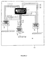
- Figure 2 is a top plan view of converter 103 of the invention.
- FIG. 1 is a block diagram of the system of the invention.
- the component source is the source of the HDMI signal.
- Component source 101 maybe a computer, specifically, the video output of a computer.
- Component source 101 may also be a DVD player, a television set, or VCR, in short, any thing that is capable of producing a signal under the HDMI standard.
- Component source 101 typically delivers the signal through a standard DVD jack, although a direct connection to a HDMI cable is also possible.
- One end of a HDMI cable 102 connects to the output of component source 101.
- Cable 102 is typically a nineteen (19) wire cable adapted specifically for transmission of HDMI signals. The other end of cable 102 connects to a converter 103.
- the connection of cable 102 to converter 103 may be done through an HDMI plug and HDMI jack or may be direct.
- Converter 103 converts the nineteen input signal into a plurality of signals suitable for twisted pair cables. In the preferred embodiment, converter 103 does not include any active components. In the preferred embodiment, converter 103 outputs to three RJ45 jacks.
- a plurality of twisted pair cables 104 have one end connected to converter 103. In the preferred embodiment, three category 5 cables each having four twisted pairs was used for cables 104. For a greater bandwidth, category 5E, category 6 or an optimized cable should be used.
- the other end of cables 104 connect to the input of a second converter 105. In the preferred embodiment, converter 105 is identical to converter 103 reversed.
- the output of converter 105 connects to an HDMI cable 106.
- HDMI cable 106 connects to a peripheral 107.
- Peripheral 107 may be a video monitor or any device having an HDMI input.
- an operational amplifier 108 such as a 941 OP Amp is placed between converter 103 and cables 104 to boost signal strength.
- FIG. 2 is a top plan view of converter 103 of the invention.
- a printed circuit board 50 forms the body of converter 103.
- Converter 103 includes an HDMI jack 11 mounted to printed circuit board 50 for inputting an HDMI signal.
- a HDMI-D Female Receptacle such as those made by Molex has been found suitable for jack 111 but other equivalent jacks could be used in either a male or female embodiment.
- Jack 111 includes nineteen pin recepticles 1-19.
- Three output jacks 37, 38, and 39 are also mounted to printed circuit board 50 included on converter 3.
- Molex CAT5 Jack w/internal shield #855070001 have been found suitable for use as output jacks 37, 38, and 39.
- Each of output jacks 37, 38, and 39 include 8 pins 40-47, 5 pins 50-54 and 6 pins 60-65, respectively. It is worth noting that the correspondence between particular pins and individual wires is a matter of design preference only and is not by way of limitation or to the exclusion of other wiring alternatives as a 8 wire, 8 wire, 3 wire alternative is equally operable variant.
- Board 50 connects pin 1 of input HDMI jack 111 to pin 40 of output jack 37. The remaining pins are connected as shown in the following table.
- a modified converter 103 maybe mounted in a wall socket (not shown) with HDMI jack 111 reversed pointing into the room and jacks 37, 38, and 39 directed toward the wall.
- Long cables (not shown) running through walls can connect two such converters to allow an unobtrusive remote monitor in a building.
- HDMI cables (not shown) are pigtails connecting to source (not shown) and output (not shown) respectively.
- a first statement of the specification is of a system for linking an HDMI producing device producing an HDMI output to a peripheral device comprising: a connection means for connecting to the output of said HDMI producing device to a HDMI cable, a converter for converting an HDMI input to a plurality of outputs, a plurality of cables each having one end connected to each of said outputs of said converter, a second converter for converting the signal received from the other end of each of said cables into an HDMI output, and a second HDMI cable for connecting the output of said second converter to a peripheral device.
- a second statement of the specification is of a system for linking an HDMI producing device producing an HDMI output to a peripheral device according to the first statement, further comprising a second connection means for connecting said cable to said peripheral device.
- a third statement of the specification is of a system for linking an HDMI producing device producing an HDMI output to a peripheral device according to the first statement, further comprising an operational amplifier connecting said converter to said cables.
- a fourth statement of the specification is of a system for linking an HDMI producing device producing an HDMI output to a peripheral device according to the first statement, wherein said plurality of cables are each comprised of a plurality of twisted pairs.
- a fifth statement of the specification is of a system for linking an HDMI producing device producing an HDMI output to a peripheral device according to the fourth statement, wherein there are four pairs in each of said plurality of cables.
- a sixth statement of the specification is of a system for linking an HDMI producing device producing an HDMI output to a peripheral device according to the fourth statement, wherein there are three of such twisted pair cables.
- a seventh statement of the specification is of a system for linking an HDMI producing device producing an HDMI output to a peripheral device according to the fourth statement, wherein there are three of such twisted pair cables and they are category 5 cables.
- An eighth statement of the specification is of a converter card for converting a 19-pin HDMI signal into a plurality of signals suitable for conduction on a plurality of multi conductor cables comprising: a 19- pin HDMI input connectable to a source of HDMI signal, a plurality of outputs for connecting to multi conductor cables, and a plurality of connections connecting each one of said 19 pins to a single conductor in one of said multi conductor cables.
- a ninth statement of the specification is of a converter card for converting a 19-pin HDMI signal into a plurality of signals suitable for conduction on a plurality of multi conductor cables according to the eighth statement, wherein there are three such outputs.
- a tenth statement of the specification is of a converter card for converting a 19-pin HDMI signal into a plurality of signals suitable for conduction on a plurality of multi conductor cables according to the ninth statement, wherein said outputs are category 5.
- An eleventh statement of the specification is of a converter card for converting a 19-pin HDMI signal into a plurality of signals suitable for conduction on a plurality of multi conductor cables according to the ninth statement, wherein said cables are category 5e.
- a twelfth statement of the specification is of a converter card for converting a 19-pin HDMI signal into a plurality of signals suitable for conduction on a plurality of multi conductor cables according to the ninth statement, wherein said cables are category 6.
- a thirteenth statement of the specification is of a method for conducting a 19-conductor HDMI signal to a distant location comprising the steps of, splitting the signal into a plurality of signals, and connecting each of said split signals into a plurality of conductors, and collecting each of said split signals into a single 19-conductor HDMI signal, receiving said collected signal at said distant location.
- a fourteenth statement of the specification is of a method for conducting a 19-conductor HDMI signal to a distant location according to the thirteenth statement where said 19 conductor signal is split into three conductor signals each conveyed by an individual cable.
- a fifteenth statement of the specification is of a method for conducting a 19-conductor HDMI signal to a distant location according to the thirteenth statement wherein said 19 conductor HDMI signal is connected to a plurality of twisted pairs in said multiconductor cables.
Landscapes
- Engineering & Computer Science (AREA)
- Multimedia (AREA)
- Signal Processing (AREA)
- Physics & Mathematics (AREA)
- Computer Hardware Design (AREA)
- General Physics & Mathematics (AREA)
- Theoretical Computer Science (AREA)
- Computer Networks & Wireless Communication (AREA)
- Two-Way Televisions, Distribution Of Moving Picture Or The Like (AREA)
- Monitoring And Testing Of Transmission In General (AREA)
- Details Of Connecting Devices For Male And Female Coupling (AREA)
Abstract
Description
- This application is a continuation in part application of and claims priority to
Application Number 10/254,485 - This invention relates to interfaces for electrical devices. In particular, the invention relates to cable with an HDMI variant of the Digital Visual Interface (DVI) for use with digital display devices called High-Definition Multimedia Interface or HDMI. With still greater particularity, the invention relates to interconnect boards for connecting an HDMI interface to multiple cables.
- The High-Definition Multimedia Interface (HDMI) is a display interface developed in response to the proliferation of digital flat-panel displays. The HDMI interface is becoming more prevalent and is expected to become widely used for digital display devices, including flat-panel displays and emerging digital CRTs. The digital HDMI connector has nineteen pins that can accommodate TMDS and optional CEC channel links as well as the VESA Enhanced DDC and EDID services. The HDMI specification defines two types of connectors. The standard HDMI cable attachable to the connector is a nineteen conductor cable. HDMI cables are expensive and cannot be used for great lengths. The longest commercially available HDMI cable is forty-eight feet in length (48'). The only available alternative to use of HDMI cables is double digital analog conversion. The digital signal from the computer must be converted to an analog signal for the analog VGA interface, then converted back to a digital signal for processing by the flat-panel display. This inherently inefficient process takes a toll on performance and video quality and adds cost. In contrast, when a display is directly connected to a digital interface, digital-to-analog conversion is not required.
- A suitable HDMI cable arrangement is an essential element of a new generation of electronic devices including digital television, High Definition Television (HDTV) and large data monitors. Such devices will need long cables as the display is often removed from the electronics.
- A problem has arisen in HDMI technology where a digital signal is required to traverse a long distance. The bandwidth required to display SXGA is 83 MHZ. If a greater resolution, such as for HDTV, is desired, the bandwidth requirement will be correspondingly larger. If standard nineteen conductor cable is used, the crosstalk and radiation along with capacitive degradation of signal making the use of long length HDMI cables untenable. If conventional coaxial cable is used, to reduce these problems, a bundle of nineteen cables is required. Accordingly, there is a longstanding demand for HDMI cable system capable of long length and reasonable cost.
- The invention makes extensive use of existing time proven cabling methods. A standard HDMI interface connector of one gender is connected to a custom connector card. The card connects the nineteen output connections of the interface to a plurality of twisted pair cables. A similar card connects the twisted pair cables to an HDMI connector of the opposite gender.
- The inventions system allows connection of devices such as displays to a remote source such as a television receiver or computer. This is accomplished with time-tested components at minimal cost. The invention may be used to string the twisted pair cables through walls with a converter at each end attachable by HDMI pigtail to the components.
- Figure 1 is a block diagram of the system of the invention.
- Figure 2 is a top plan view of
converter 103 of the invention. - Figure 1 is a block diagram of the system of the invention. The component source is the source of the HDMI signal.
Component source 101 maybe a computer, specifically, the video output of a computer.Component source 101 may also be a DVD player, a television set, or VCR, in short, any thing that is capable of producing a signal under the HDMI standard.Component source 101 typically delivers the signal through a standard DVD jack, although a direct connection to a HDMI cable is also possible. One end of aHDMI cable 102 connects to the output ofcomponent source 101.Cable 102 is typically a nineteen (19) wire cable adapted specifically for transmission of HDMI signals. The other end ofcable 102 connects to aconverter 103. The connection ofcable 102 to converter 103 may be done through an HDMI plug and HDMI jack or may be direct. Converter 103 converts the nineteen input signal into a plurality of signals suitable for twisted pair cables. In the preferred embodiment,converter 103 does not include any active components. In the preferred embodiment, converter 103 outputs to three RJ45 jacks. A plurality oftwisted pair cables 104 have one end connected toconverter 103. In the preferred embodiment, three category 5 cables each having four twisted pairs was used forcables 104. For a greater bandwidth, category 5E,category 6 or an optimized cable should be used. The other end ofcables 104 connect to the input of asecond converter 105. In the preferred embodiment,converter 105 is identical toconverter 103 reversed. The output ofconverter 105 connects to anHDMI cable 106.HDMI cable 106 connects to a peripheral 107. Peripheral 107 may be a video monitor or any device having an HDMI input. In an optional embodiment, anoperational amplifier 108 such as a 941 OP Amp is placed betweenconverter 103 andcables 104 to boost signal strength. - Figure 2 is a top plan view of
converter 103 of the invention. A printedcircuit board 50 forms the body ofconverter 103.Converter 103 includes anHDMI jack 11 mounted to printedcircuit board 50 for inputting an HDMI signal. A HDMI-D Female Receptacle such as those made by Molex has been found suitable forjack 111 but other equivalent jacks could be used in either a male or female embodiment. Jack 111 includes nineteen pin recepticles 1-19. Threeoutput jacks circuit board 50 included on converter 3. Molex CAT5 Jack w/internal shield #855070001 have been found suitable for use asoutput jacks output jacks Board 50 connects pin 1 ofinput HDMI jack 111 to pin 40 ofoutput jack 37. The remaining pins are connected as shown in the following table.Table 1 Jack 37pin 40 toHDMI jack 11 pin 1TMDS Data2+ Jack 37 pin 41 toHDMI jack 11pin 2 TMDSData2 Shield Jack 37 pin 42 toHDMI jack 11 pin 3 TMDS Data2-Jack 37pin 43 toHDMI jack 11pin 4TMDS Data1+ Jack 37 pin 44 toHDMI jack 11 pin 5 TMDSData1 Shield Jack 37 pin 45 toHDMI jack 11pin 6 TMDS Data1-Jack 37 pin 46 toHDMI jack 11 pin 7TMDS Data0+ Jack 37 pin 47 toHDMI jack 11pin 8 TMDSData0 Shield Jack 38 pin 50 toHDMI jack 11pin 9 TMDS Data0-Jack 38pin 51 toHDMI jack 11pin 10TMDS Clock+ Jack 38 pin 52 toHDMI jack 11pin 11 TMDS Clock Shield-->Jack 38pin 53 toHDMI jack 11pin 12 TMDS Clock-Jack 38pin 54 toHDMI jack 11pin 13 CEC (not used)Jack 39pin 60 toHDMI jack 11pin 14 Reserved (N.C. on device)Jack 39pin 61 toHDMI jack 11pin 15SCL Jack 39 pin 62 toHDMI jack 11pin 16SDA Jack 39 pin 63 toHDMI jack 11pin 17 DDC/CEC Ground Jack 39 pin 64 toHDMI jack 11pin 18 +5V Power Jack 39 pin 65 toHDMI jack 11pin 19 Hot Plug Detect - A modified
converter 103 maybe mounted in a wall socket (not shown) withHDMI jack 111 reversed pointing into the room and jacks 37, 38, and 39 directed toward the wall. Long cables (not shown) running through walls can connect two such converters to allow an unobtrusive remote monitor in a building. HDMI cables (not shown) are pigtails connecting to source (not shown) and output (not shown) respectively. - The present invention has been particularly shown and described with respect to certain preferred embodiments and features thereof. However, it should be readily apparent to those of ordinary skill in the art that various changes and modifications in form and detail may be made without departing from the spirit and scope of the inventions as set forth in the appended claims, in which reference to an element in the singular is not intended to mean "one and only one" unless explicitly so stated, but rather "one or more". The inventions illustratively disclosed herein may be practiced without any element which is not specifically disclosed herein.
A first statement of the specification is of a system for linking an HDMI producing device producing an HDMI output to a peripheral device comprising: a connection means for connecting to the output of said HDMI producing device to a HDMI cable, a converter for converting an HDMI input to a plurality of outputs, a plurality of cables each having one end connected to each of said outputs of said converter, a second converter for converting the signal received from the other end of each of said cables into an HDMI output, and a second HDMI cable for connecting the output of said second converter to a peripheral device.
A second statement of the specification is of a system for linking an HDMI producing device producing an HDMI output to a peripheral device according to the first statement, further comprising a second connection means for connecting said cable to said peripheral device.
A third statement of the specification is of a system for linking an HDMI producing device producing an HDMI output to a peripheral device according to the first statement, further comprising an operational amplifier connecting said converter to said cables.
A fourth statement of the specification is of a system for linking an HDMI producing device producing an HDMI output to a peripheral device according to the first statement, wherein said plurality of cables are each comprised of a plurality of twisted pairs.
A fifth statement of the specification is of a system for linking an HDMI producing device producing an HDMI output to a peripheral device according to the fourth statement, wherein there are four pairs in each of said plurality of cables.
A sixth statement of the specification is of a system for linking an HDMI producing device producing an HDMI output to a peripheral device according to the fourth statement, wherein there are three of such twisted pair cables.
A seventh statement of the specification is of a system for linking an HDMI producing device producing an HDMI output to a peripheral device according to the fourth statement, wherein there are three of such twisted pair cables and they are category 5 cables.
An eighth statement of the specification is of a converter card for converting a 19-pin HDMI signal into a plurality of signals suitable for conduction on a plurality of multi conductor cables comprising: a 19- pin HDMI input connectable to a source of HDMI signal, a plurality of outputs for connecting to multi conductor cables, and a plurality of connections connecting each one of said 19 pins to a single conductor in one of said multi conductor cables.
A ninth statement of the specification is of a converter card for converting a 19-pin HDMI signal into a plurality of signals suitable for conduction on a plurality of multi conductor cables according to the eighth statement, wherein there are three such outputs.
A tenth statement of the specification is of a converter card for converting a 19-pin HDMI signal into a plurality of signals suitable for conduction on a plurality of multi conductor cables according to the ninth statement, wherein said outputs are category 5.
An eleventh statement of the specification is of a converter card for converting a 19-pin HDMI signal into a plurality of signals suitable for conduction on a plurality of multi conductor cables according to the ninth statement, wherein said cables are category 5e.
A twelfth statement of the specification is of a converter card for converting a 19-pin HDMI signal into a plurality of signals suitable for conduction on a plurality of multi conductor cables according to the ninth statement, wherein said cables arecategory 6.
A thirteenth statement of the specification is of a method for conducting a 19-conductor HDMI signal to a distant location comprising the steps of, splitting the signal into a plurality of signals, and connecting each of said split signals into a plurality of conductors, and collecting each of said split signals into a single 19-conductor HDMI signal, receiving said collected signal at said distant location.
A fourteenth statement of the specification is of a method for conducting a 19-conductor HDMI signal to a distant location according to the thirteenth statement where said 19 conductor signal is split into three conductor signals each conveyed by an individual cable.
A fifteenth statement of the specification is of a method for conducting a 19-conductor HDMI signal to a distant location according to the thirteenth statement wherein said 19 conductor HDMI signal is connected to a plurality of twisted pairs in said multiconductor cables.
Claims (3)
- A method for conducting a 19-conductor HDMI signal to a distant location comprising the steps of, splitting the signal into a plurality of signals, and connecting each of said split signals into a plurality of conductors, and collecting each of said split signals into a single 19-conductor HDMI signal, receiving said collected signal at said distant location.
- A method for conducting a 19-conductor HDMI signal to a distant location as in claim 1 where said 19 conductor signal is split into three conductor signals each conveyed by an individual cable.
- A method for conducting a 19-conductor HDMI signal to a distant location as in claim 1 wherein said 19 conductor HDMI signal is connected to a plurality of twisted pairs in said multiconductor cables.
Applications Claiming Priority (2)
| Application Number | Priority Date | Filing Date | Title |
|---|---|---|---|
| US11/202,950 US20060036788A1 (en) | 2002-09-24 | 2005-08-12 | HDMI cable interface |
| EP06016961A EP1755199A3 (en) | 2005-08-12 | 2006-08-14 | HDMI cable interface |
Related Parent Applications (1)
| Application Number | Title | Priority Date | Filing Date |
|---|---|---|---|
| EP06016961A Division EP1755199A3 (en) | 2005-08-12 | 2006-08-14 | HDMI cable interface |
Publications (2)
| Publication Number | Publication Date |
|---|---|
| EP1890364A2 true EP1890364A2 (en) | 2008-02-20 |
| EP1890364A3 EP1890364A3 (en) | 2008-05-14 |
Family
ID=37453222
Family Applications (3)
| Application Number | Title | Priority Date | Filing Date |
|---|---|---|---|
| EP07022114A Ceased EP1890365A3 (en) | 2005-08-12 | 2006-08-14 | HDMI cable interface |
| EP07022111A Ceased EP1890364A3 (en) | 2005-08-12 | 2006-08-14 | HDMI cable interface |
| EP06016961A Ceased EP1755199A3 (en) | 2005-08-12 | 2006-08-14 | HDMI cable interface |
Family Applications Before (1)
| Application Number | Title | Priority Date | Filing Date |
|---|---|---|---|
| EP07022114A Ceased EP1890365A3 (en) | 2005-08-12 | 2006-08-14 | HDMI cable interface |
Family Applications After (1)
| Application Number | Title | Priority Date | Filing Date |
|---|---|---|---|
| EP06016961A Ceased EP1755199A3 (en) | 2005-08-12 | 2006-08-14 | HDMI cable interface |
Country Status (3)
| Country | Link |
|---|---|
| US (1) | US20060036788A1 (en) |
| EP (3) | EP1890365A3 (en) |
| CN (2) | CN101795380B (en) |
Cited By (1)
| Publication number | Priority date | Publication date | Assignee | Title |
|---|---|---|---|---|
| EP2453529A1 (en) * | 2010-11-12 | 2012-05-16 | Samsung Electronics Co., Ltd. | Connector and interface device |
Families Citing this family (68)
| Publication number | Priority date | Publication date | Assignee | Title |
|---|---|---|---|---|
| US7620062B2 (en) * | 2003-05-01 | 2009-11-17 | Genesis Microchips Inc. | Method of real time optimizing multimedia packet transmission rate |
| US8059673B2 (en) | 2003-05-01 | 2011-11-15 | Genesis Microchip Inc. | Dynamic resource re-allocation in a packet based video display interface |
| US20040218599A1 (en) * | 2003-05-01 | 2004-11-04 | Genesis Microchip Inc. | Packet based video display interface and methods of use thereof |
| US20040221315A1 (en) * | 2003-05-01 | 2004-11-04 | Genesis Microchip Inc. | Video interface arranged to provide pixel data independent of a link character clock |
| US7839860B2 (en) * | 2003-05-01 | 2010-11-23 | Genesis Microchip Inc. | Packet based video display interface |
| US8068485B2 (en) * | 2003-05-01 | 2011-11-29 | Genesis Microchip Inc. | Multimedia interface |
| US20040221312A1 (en) * | 2003-05-01 | 2004-11-04 | Genesis Microchip Inc. | Techniques for reducing multimedia data packet overhead |
| US7405719B2 (en) * | 2003-05-01 | 2008-07-29 | Genesis Microchip Inc. | Using packet transfer for driving LCD panel driver electronics |
| US7733915B2 (en) * | 2003-05-01 | 2010-06-08 | Genesis Microchip Inc. | Minimizing buffer requirements in a digital video system |
| US20040218624A1 (en) * | 2003-05-01 | 2004-11-04 | Genesis Microchip Inc. | Packet based closed loop video display interface with periodic status checks |
| US8204076B2 (en) * | 2003-05-01 | 2012-06-19 | Genesis Microchip Inc. | Compact packet based multimedia interface |
| US7800623B2 (en) * | 2003-09-18 | 2010-09-21 | Genesis Microchip Inc. | Bypassing pixel clock generation and CRTC circuits in a graphics controller chip |
| US7634090B2 (en) * | 2003-09-26 | 2009-12-15 | Genesis Microchip Inc. | Packet based high definition high-bandwidth digital content protection |
| US7613300B2 (en) * | 2003-09-26 | 2009-11-03 | Genesis Microchip Inc. | Content-protected digital link over a single signal line |
| US7347632B2 (en) * | 2003-12-12 | 2008-03-25 | Mina Farr | Optical connectors for electronic devices |
| US7706692B2 (en) | 2004-09-29 | 2010-04-27 | Finisar Corporation | Consumer electronics with optical communication interface |
| US20060280055A1 (en) * | 2005-06-08 | 2006-12-14 | Miller Rodney D | Laser power control and device status monitoring for video/graphic applications |
| US7331819B2 (en) * | 2005-07-11 | 2008-02-19 | Finisar Corporation | Media converter |
| US7729618B2 (en) | 2005-08-30 | 2010-06-01 | Finisar Corporation | Optical networks for consumer electronics |
| US7860398B2 (en) * | 2005-09-15 | 2010-12-28 | Finisar Corporation | Laser drivers for closed path optical cables |
| US20070206641A1 (en) * | 2005-11-10 | 2007-09-06 | X-Emi, Inc. | Encoding and deserialization-serialization for digital signals |
| US7401985B2 (en) * | 2006-04-10 | 2008-07-22 | Finisar Corporation | Electrical-optical active optical cable |
| US7876989B2 (en) * | 2006-04-10 | 2011-01-25 | Finisar Corporation | Active optical cable with integrated power |
| US8083417B2 (en) * | 2006-04-10 | 2011-12-27 | Finisar Corporation | Active optical cable electrical adaptor |
| US7445389B2 (en) | 2006-04-10 | 2008-11-04 | Finisar Corporation | Active optical cable with integrated eye safety |
| US7499616B2 (en) | 2006-04-10 | 2009-03-03 | Finisar Corporation | Active optical cable with electrical connector |
| US7712976B2 (en) | 2006-04-10 | 2010-05-11 | Finisar Corporation | Active optical cable with integrated retiming |
| US7778510B2 (en) * | 2006-04-10 | 2010-08-17 | Finisar Corporation | Active optical cable electrical connector |
| US7576663B2 (en) * | 2006-04-21 | 2009-08-18 | Locolabs, Llc | Inline audio/visual conversion |
| EP2023632B1 (en) | 2006-05-16 | 2013-10-02 | Sony Corporation | Communication system, transmission device, reception device, communication method, and program |
| KR20080040459A (en) * | 2006-11-03 | 2008-05-08 | 삼성전자주식회사 | Method for recognizing digital interface and the image display apparatus thereof |
| CN102065262B (en) | 2006-11-07 | 2013-04-03 | 索尼株式会社 | Electronic device and control information reception method |
| US20100269137A1 (en) | 2006-11-07 | 2010-10-21 | Sony Corporation | Transmission device, video signal transmission method for transmission device, reception device, and video signal reception method for reception device |
| US8565337B2 (en) * | 2007-02-07 | 2013-10-22 | Valens Semiconductor Ltd. | Devices for transmitting digital video and data over the same wires |
| US8769171B2 (en) * | 2007-04-06 | 2014-07-01 | Finisar Corporation | Electrical device with electrical interface that is compatible with integrated optical cable receptacle |
| US8244124B2 (en) | 2007-04-30 | 2012-08-14 | Finisar Corporation | Eye safety mechanism for use in optical cable with electrical interfaces |
| US20090049498A1 (en) * | 2007-08-18 | 2009-02-19 | Changrong Li | Method to Extend HDMI and DVI Connections over Long Distances |
| US20090052208A1 (en) * | 2007-08-25 | 2009-02-26 | Changrong Li | Apparatus to Extend HDMI Connections over a Single Ethernet CAT Cable |
| US8316163B2 (en) * | 2007-09-10 | 2012-11-20 | John Mezzalingua Associates, Inc. | HDMI-quality content transmission along a single medium |
| US20090094658A1 (en) * | 2007-10-09 | 2009-04-09 | Genesis Microchip Inc. | Methods and systems for driving multiple displays |
| US20090219932A1 (en) * | 2008-02-04 | 2009-09-03 | Stmicroelectronics, Inc. | Multi-stream data transport and methods of use |
| US8098690B2 (en) * | 2008-03-18 | 2012-01-17 | Transwitch Corporation | System and method for transferring high-definition multimedia signals over four twisted-pairs |
| US9112789B2 (en) * | 2008-08-15 | 2015-08-18 | Tellabs Operations, Inc. | Method and apparatus for simplifying planning and tracking of multiple installation configurations |
| US20100183004A1 (en) * | 2009-01-16 | 2010-07-22 | Stmicroelectronics, Inc. | System and method for dual mode communication between devices in a network |
| US8760461B2 (en) | 2009-05-13 | 2014-06-24 | Stmicroelectronics, Inc. | Device, system, and method for wide gamut color space support |
| US8429440B2 (en) * | 2009-05-13 | 2013-04-23 | Stmicroelectronics, Inc. | Flat panel display driver method and system |
| US8156238B2 (en) * | 2009-05-13 | 2012-04-10 | Stmicroelectronics, Inc. | Wireless multimedia transport method and apparatus |
| US8860888B2 (en) * | 2009-05-13 | 2014-10-14 | Stmicroelectronics, Inc. | Method and apparatus for power saving during video blanking periods |
| US8370554B2 (en) * | 2009-05-18 | 2013-02-05 | Stmicroelectronics, Inc. | Operation of video source and sink with hot plug detection not asserted |
| US8582452B2 (en) | 2009-05-18 | 2013-11-12 | Stmicroelectronics, Inc. | Data link configuration by a receiver in the absence of link training data |
| US8468285B2 (en) * | 2009-05-18 | 2013-06-18 | Stmicroelectronics, Inc. | Operation of video source and sink with toggled hot plug detection |
| US8291207B2 (en) * | 2009-05-18 | 2012-10-16 | Stmicroelectronics, Inc. | Frequency and symbol locking using signal generated clock frequency and symbol identification |
| US8671234B2 (en) | 2010-05-27 | 2014-03-11 | Stmicroelectronics, Inc. | Level shifting cable adaptor and chip system for use with dual-mode multi-media device |
| US20120210384A1 (en) * | 2011-02-15 | 2012-08-16 | Madalin Cirstea | High definition video extender and method |
| US8776163B2 (en) * | 2011-02-15 | 2014-07-08 | Video Products, Inc. | High definition video extender and method |
| US8724343B2 (en) | 2011-06-27 | 2014-05-13 | Crestron Electronics Inc. | Hi-definition multimedia interface shield with fingers |
| US8854835B2 (en) | 2011-06-27 | 2014-10-07 | Crestron Electronics Inc. | Hi-definition multimedia interface shield with fingers |
| WO2013002547A2 (en) | 2011-06-30 | 2013-01-03 | 주식회사 케이티 | Portable terminal capable of docking with an external device and method for controlling same |
| KR101554599B1 (en) | 2011-06-30 | 2015-09-21 | 주식회사 케이티 | Mobile Terminal for connection with external device, and method for running application thereof |
| KR101474927B1 (en) | 2011-12-22 | 2014-12-31 | 주식회사 케이티 | Method for outputting image data from terminal to display device and terminal thereof |
| KR101546407B1 (en) | 2011-12-23 | 2015-08-24 | 주식회사 케이티 | Method and apparatus for execution controlling of application |
| KR101522399B1 (en) | 2011-12-23 | 2015-05-22 | 주식회사 케이티 | Method for displaying image from handheld terminal to display device and handheld terminal thereof |
| KR101522397B1 (en) | 2011-12-26 | 2015-05-22 | 주식회사 케이티 | Mobile terminal capable of connecting to multiple external devices and control method thereof |
| KR101504655B1 (en) | 2011-12-26 | 2015-03-23 | 주식회사 케이티 | Method and apparatus for controlling application execution |
| US8742266B2 (en) | 2012-02-28 | 2014-06-03 | Creston Electronics Inc. | Hi-definition multimedia interface gasket with fingers |
| US20140327751A1 (en) * | 2012-12-31 | 2014-11-06 | Timothy King | High definition (hd) inter-module link interface |
| US9697157B2 (en) * | 2013-08-28 | 2017-07-04 | Vanco International, Llc | Multi-connectivity boost extender and connectivity device |
| US9747236B2 (en) | 2015-04-07 | 2017-08-29 | Vanco International, Llc | HDMI extender with bidirectional power over twisted pair |
Family Cites Families (13)
| Publication number | Priority date | Publication date | Assignee | Title |
|---|---|---|---|---|
| US6007372A (en) * | 1996-09-18 | 1999-12-28 | Delorme Publishing Co. | GPS power/data cable system |
| US5938754A (en) * | 1997-11-26 | 1999-08-17 | National Instruments Corporation | Fieldbus connector including dual connectors |
| US6231379B1 (en) * | 1999-12-28 | 2001-05-15 | Innmaging Quality Technology, Inc. | VGA cable adapter for transmitting video signals |
| TWI282691B (en) * | 2001-03-23 | 2007-06-11 | Matsushita Electric Ind Co Ltd | Data-transmission method, data-transmission device, data-reception method and data reception device |
| US20040015991A1 (en) | 2002-07-18 | 2004-01-22 | Barry Thornton | Digital visual interface cable distance extension |
| JP2004213949A (en) * | 2002-12-27 | 2004-07-29 | Tyco Electronics Amp Kk | Electric cable assembly |
| JP3979300B2 (en) * | 2003-02-10 | 2007-09-19 | 住友電気工業株式会社 | Interface module for digital video signal transmission |
| US20040181806A1 (en) * | 2003-03-11 | 2004-09-16 | Visual Circuits Corporation | Method and apparatus for transmitting digital video signals in a digital visual interface format over an RF cable |
| KR100517502B1 (en) * | 2003-05-26 | 2005-09-28 | 삼성전자주식회사 | Apparatus and method for reproducing signal from DVI/HDMI compatible connector |
| JP2005057714A (en) * | 2003-07-31 | 2005-03-03 | Toshiba Corp | Transmitter and transmitting method |
| KR100565059B1 (en) * | 2003-08-25 | 2006-03-30 | 삼성전자주식회사 | Apparatus and method for converting output picture |
| JP2005109703A (en) * | 2003-09-29 | 2005-04-21 | Pioneer Electronic Corp | Apparatus and method for outputting image, image display system, image output program and information recording medium |
| US7321946B2 (en) * | 2004-07-07 | 2008-01-22 | Infocus Corporation | Link extender having equalization circuitry |
-
2005
- 2005-08-12 US US11/202,950 patent/US20060036788A1/en not_active Abandoned
-
2006
- 2006-08-14 EP EP07022114A patent/EP1890365A3/en not_active Ceased
- 2006-08-14 CN CN201010145605.1A patent/CN101795380B/en not_active Expired - Fee Related
- 2006-08-14 CN CN2006101098106A patent/CN1913613B/en not_active Expired - Fee Related
- 2006-08-14 EP EP07022111A patent/EP1890364A3/en not_active Ceased
- 2006-08-14 EP EP06016961A patent/EP1755199A3/en not_active Ceased
Non-Patent Citations (1)
| Title |
|---|
| 8 March 2005 (2005-03-08), Retrieved from the Internet <URL:http://web.archive.org/web/20050308035611/http://www.svideo.com/ext-hdtv-cat5.html> [retrieved on 20100127] * |
Cited By (2)
| Publication number | Priority date | Publication date | Assignee | Title |
|---|---|---|---|---|
| EP2453529A1 (en) * | 2010-11-12 | 2012-05-16 | Samsung Electronics Co., Ltd. | Connector and interface device |
| EP2568545A1 (en) * | 2010-11-12 | 2013-03-13 | Samsung Electronics Co., Ltd. | Connector and interface device |
Also Published As
| Publication number | Publication date |
|---|---|
| US20060036788A1 (en) | 2006-02-16 |
| CN101795380B (en) | 2015-07-22 |
| EP1890364A3 (en) | 2008-05-14 |
| EP1755199A3 (en) | 2007-09-12 |
| EP1755199A2 (en) | 2007-02-21 |
| CN101795380A (en) | 2010-08-04 |
| EP1890365A2 (en) | 2008-02-20 |
| EP1890365A3 (en) | 2008-05-14 |
| CN1913613B (en) | 2010-05-26 |
| CN1913613A (en) | 2007-02-14 |
Similar Documents
| Publication | Publication Date | Title |
|---|---|---|
| EP1890364A2 (en) | HDMI cable interface | |
| US6941395B1 (en) | DVI cable interface | |
| US7818462B2 (en) | Cable interface | |
| CN101727873B (en) | Signal conversion apparatuses and display system | |
| US8957941B2 (en) | Enhanced power supply | |
| EP2624510B1 (en) | Transmission apparatus, transmission method, reception apparatus, reception method, transmission/reception system, and cable | |
| US20120077384A1 (en) | Apparatus for enabling simultaneous content streaming and power charging of handheld devices | |
| EP1445951A2 (en) | Interface module for transmitting digital video signal | |
| US6790094B1 (en) | Connector to couple a monitor to a computer | |
| CN101015180A (en) | Link extender | |
| JP2005049818A (en) | Method for minimizing buffer requirement in digital video system | |
| JP2009009106A (en) | Multimedia interface | |
| JP2005051740A (en) | Technique for reducing multimedia data packet overhead | |
| CN209748734U (en) | Image transmission system | |
| CN2805272Y (en) | DAVI connector which can transmit digital video signals and digital sound signals | |
| CN1275135C (en) | Long-distance video pattern array signal transmission device | |
| TW200929919A (en) | Display signal extender and a method of transmitting display signal by using the same | |
| EP1845589A1 (en) | Computer system having analog and digital video signal output functionality, and computer device and video signal transmitting device thereof | |
| CN210223511U (en) | Display driving board | |
| CN101437132A (en) | Multimedia terminal and implementing method thereof | |
| CN105867871A (en) | Display adapter | |
| CN111627344A (en) | LED display panel and framework of LED display screen | |
| CN201298340Y (en) | Video card including scalable link interface system and adapter of same | |
| CN218867582U (en) | Data line and video signal transmission device | |
| CN112952503A (en) | Multi-interface adapter |
Legal Events
| Date | Code | Title | Description |
|---|---|---|---|
| PUAI | Public reference made under article 153(3) epc to a published international application that has entered the european phase |
Free format text: ORIGINAL CODE: 0009012 |
|
| AC | Divisional application: reference to earlier application |
Ref document number: 1755199 Country of ref document: EP Kind code of ref document: P |
|
| AK | Designated contracting states |
Kind code of ref document: A2 Designated state(s): AT BE BG CH CY CZ DE DK EE ES FI FR GB GR HU IE IS IT LI LT LU LV MC NL PL PT RO SE SI SK TR |
|
| AX | Request for extension of the european patent |
Extension state: AL BA HR MK YU |
|
| PUAL | Search report despatched |
Free format text: ORIGINAL CODE: 0009013 |
|
| AK | Designated contracting states |
Kind code of ref document: A3 Designated state(s): AT BE BG CH CY CZ DE DK EE ES FI FR GB GR HU IE IS IT LI LT LU LV MC NL PL PT RO SE SI SK TR |
|
| AX | Request for extension of the european patent |
Extension state: AL BA HR MK RS |
|
| 17P | Request for examination filed |
Effective date: 20080731 |
|
| AKX | Designation fees paid |
Designated state(s): AT BE BG CH CY CZ DE DK EE ES FI FR GB GR HU IE IS IT LI LT LU LV MC NL PL PT RO SE SI SK TR |
|
| 17Q | First examination report despatched |
Effective date: 20100205 |
|
| RBV | Designated contracting states (corrected) |
Designated state(s): AT BE BG CH CY CZ DE DK EE ES FI FR GB GR HU IE IS IT LI LT LU LV MC NL PL PT RO SE SI SK TR |
|
| RBV | Designated contracting states (corrected) |
Designated state(s): DE ES FR GB IT |
|
| STAA | Information on the status of an ep patent application or granted ep patent |
Free format text: STATUS: THE APPLICATION HAS BEEN REFUSED |
|
| 18R | Application refused |
Effective date: 20130318 |