US8098690B2 - System and method for transferring high-definition multimedia signals over four twisted-pairs - Google Patents
System and method for transferring high-definition multimedia signals over four twisted-pairs Download PDFInfo
- Publication number
- US8098690B2 US8098690B2 US12/050,632 US5063208A US8098690B2 US 8098690 B2 US8098690 B2 US 8098690B2 US 5063208 A US5063208 A US 5063208A US 8098690 B2 US8098690 B2 US 8098690B2
- Authority
- US
- United States
- Prior art keywords
- sink
- multimedia
- channel
- source
- data
- Prior art date
- Legal status (The legal status is an assumption and is not a legal conclusion. Google has not performed a legal analysis and makes no representation as to the accuracy of the status listed.)
- Expired - Fee Related, expires
Links
- 238000000034 method Methods 0.000 title claims abstract description 18
- 230000011664 signaling Effects 0.000 claims description 5
- 230000007704 transition Effects 0.000 claims description 5
- 238000001914 filtration Methods 0.000 claims 8
- GJWAPAVRQYYSTK-UHFFFAOYSA-N [(dimethyl-$l^{3}-silanyl)amino]-dimethylsilicon Chemical compound C[Si](C)N[Si](C)C GJWAPAVRQYYSTK-UHFFFAOYSA-N 0.000 description 14
- 238000010586 diagram Methods 0.000 description 8
- 230000005540 biological transmission Effects 0.000 description 5
- 230000006870 function Effects 0.000 description 5
- 238000011084 recovery Methods 0.000 description 3
- 238000013459 approach Methods 0.000 description 1
- 230000002457 bidirectional effect Effects 0.000 description 1
- 239000000470 constituent Substances 0.000 description 1
- 230000009977 dual effect Effects 0.000 description 1
- 238000009434 installation Methods 0.000 description 1
- 230000008054 signal transmission Effects 0.000 description 1
- 230000001360 synchronised effect Effects 0.000 description 1
- 230000000007 visual effect Effects 0.000 description 1
Images


Classifications
-
- H—ELECTRICITY
- H04—ELECTRIC COMMUNICATION TECHNIQUE
- H04N—PICTORIAL COMMUNICATION, e.g. TELEVISION
- H04N7/00—Television systems
- H04N7/16—Analogue secrecy systems; Analogue subscription systems
- H04N7/162—Authorising the user terminal, e.g. by paying; Registering the use of a subscription channel, e.g. billing
- H04N7/163—Authorising the user terminal, e.g. by paying; Registering the use of a subscription channel, e.g. billing by receiver means only
-
- G—PHYSICS
- G09—EDUCATION; CRYPTOGRAPHY; DISPLAY; ADVERTISING; SEALS
- G09G—ARRANGEMENTS OR CIRCUITS FOR CONTROL OF INDICATING DEVICES USING STATIC MEANS TO PRESENT VARIABLE INFORMATION
- G09G5/00—Control arrangements or circuits for visual indicators common to cathode-ray tube indicators and other visual indicators
- G09G5/003—Details of a display terminal, the details relating to the control arrangement of the display terminal and to the interfaces thereto
- G09G5/006—Details of the interface to the display terminal
-
- H—ELECTRICITY
- H04—ELECTRIC COMMUNICATION TECHNIQUE
- H04N—PICTORIAL COMMUNICATION, e.g. TELEVISION
- H04N21/00—Selective content distribution, e.g. interactive television or video on demand [VOD]
- H04N21/40—Client devices specifically adapted for the reception of or interaction with content, e.g. set-top-box [STB]; Operations thereof
- H04N21/41—Structure of client; Structure of client peripherals
- H04N21/4104—Peripherals receiving signals from specially adapted client devices
- H04N21/4122—Peripherals receiving signals from specially adapted client devices additional display device, e.g. video projector
-
- H—ELECTRICITY
- H04—ELECTRIC COMMUNICATION TECHNIQUE
- H04N—PICTORIAL COMMUNICATION, e.g. TELEVISION
- H04N21/00—Selective content distribution, e.g. interactive television or video on demand [VOD]
- H04N21/40—Client devices specifically adapted for the reception of or interaction with content, e.g. set-top-box [STB]; Operations thereof
- H04N21/43—Processing of content or additional data, e.g. demultiplexing additional data from a digital video stream; Elementary client operations, e.g. monitoring of home network or synchronising decoder's clock; Client middleware
- H04N21/436—Interfacing a local distribution network, e.g. communicating with another STB or one or more peripheral devices inside the home
- H04N21/4363—Adapting the video or multiplex stream to a specific local network, e.g. a IEEE 1394 or Bluetooth® network
- H04N21/43632—Adapting the video or multiplex stream to a specific local network, e.g. a IEEE 1394 or Bluetooth® network involving a wired protocol, e.g. IEEE 1394
-
- G—PHYSICS
- G09—EDUCATION; CRYPTOGRAPHY; DISPLAY; ADVERTISING; SEALS
- G09G—ARRANGEMENTS OR CIRCUITS FOR CONTROL OF INDICATING DEVICES USING STATIC MEANS TO PRESENT VARIABLE INFORMATION
- G09G2370/00—Aspects of data communication
- G09G2370/04—Exchange of auxiliary data, i.e. other than image data, between monitor and graphics controller
- G09G2370/045—Exchange of auxiliary data, i.e. other than image data, between monitor and graphics controller using multiple communication channels, e.g. parallel and serial
- G09G2370/047—Exchange of auxiliary data, i.e. other than image data, between monitor and graphics controller using multiple communication channels, e.g. parallel and serial using display data channel standard [DDC] communication
-
- G—PHYSICS
- G09—EDUCATION; CRYPTOGRAPHY; DISPLAY; ADVERTISING; SEALS
- G09G—ARRANGEMENTS OR CIRCUITS FOR CONTROL OF INDICATING DEVICES USING STATIC MEANS TO PRESENT VARIABLE INFORMATION
- G09G2370/00—Aspects of data communication
- G09G2370/12—Use of DVI or HDMI protocol in interfaces along the display data pipeline
-
- H—ELECTRICITY
- H04—ELECTRIC COMMUNICATION TECHNIQUE
- H04L—TRANSMISSION OF DIGITAL INFORMATION, e.g. TELEGRAPHIC COMMUNICATION
- H04L7/00—Arrangements for synchronising receiver with transmitter
- H04L7/0008—Synchronisation information channels, e.g. clock distribution lines
Definitions
- This invention generally relates to electronic display device connectivity.
- the high-definition multimedia interface is a licensable compact audio/video connector interface for transmitting uncompressed digital streams.
- the HDMI connects digital audio/video (or multimedia) sources (e.g., a set-top box, a DVD player, a personal computer, a video game console, etc.) to a compatible digital audio device and/or video monitor such as a digital television.
- digital audio/video sources e.g., a set-top box, a DVD player, a personal computer, a video game console, etc.
- DRM digital rights management
- a block diagram of a HDMI link 100 is shown in FIG. 1 .
- a multimedia source 110 transmits high speed data using transition minimized differential signaling (TMDS®) characters.
- the TMDS characters encapsulate video, audio, and auxiliary data and are carried over three TMDS channels 130 - 1 , 130 - 2 , and 130 - 3 .
- TMDS characters are transported at three different time periods: a video data period, a data island period, and a control period.
- the video data period the pixels of an active video line are transmitted.
- audio and auxiliary data are transmitted within a series of packets. Control codes are transported during the control period, which occurs between video and data island periods.
- the control codes include, for example, encryption status signals (ESS), HSYNC signals, VSYNC signals, and delimiters.
- a multimedia sink 120 receives the TMDS characters and converts them into digital video streams, data packets, ESS, HSYNC and VSYNC signals.
- a clock typically running at the video pixel rate, is transmitted on a clock channel 140 and is used by the multimedia sink 120 as a frequency reference for data recovery on the three TMDS channels 130 .
- the system-level control includes display data channel (DDC) and consumer electronics control (CEC) which are transmitted over channels: SCL 150 , SDA 160 , and CEC 170 .
- the DDC is used for exchanging configuration and status information between the multimedia source 110 and sink 120 .
- the CEC protocol provides high-level control functions between all of the various audiovisual products in a user's environment.
- the SDA 160 and CEC 170 are bidirectional channels, while the SCL 150 is unidirectional channel (from source 110 to sink 120 ).
- a standard HDMI interface further includes a hot-plug detect (HPD) signal 180 which originates at the sink 120 .
- HPD hot-plug detect
- each channel is a twisted-pair wire.
- the multimedia source 110 and multimedia sink 120 are physically coupled using an HDMI cable that is designed to channel at least the signals 130 through 180 .
- the HDMI standard defines different categories of HDMI cables, each of which has a different purpose and a unique connector type.
- the performance of a typical HDMI cable is usually a function of its length. For example, high quality cables can reach, at most, up to 15 meters.
- Another disadvantage of standard HDMI cables is their cost. Typically, such cables are significantly more expensive than other cabling standards, e.g., coaxial and RCA cabling.
- Cat-5 is a twisted pair cable type designed for high signal integrity. This type of cable is often used in structured cabling for computer networks (e.g., Ethernet) and many other signals such as basic voice services.
- a Cat-5 cable includes four twisted pairs in a single cable jacket. This use of balanced lines helps preserve a high signal-to-noise ratio despite interference from both external sources and other pairs.
- FIG. 1 is a block diagram of an HDMI link.
- FIG. 2 is a block diagram of a system for transferring high definition multimedia signals constructed in accordance with an embodiment of the invention.
- FIG. 3 is a block diagram of a data multiplexing circuit and a data demultiplexing circuit implemented in accordance with an embodiment of the invention.
- FIG. 4 is a block diagram of a source clock and data handler and a sink clock and data handler implemented in accordance with an embodiment of the invention.
- FIG. 5 is a flowchart describing a method for transferring high definition multimedia signals over four twisted pairs implemented in accordance with an embodiment of the invention.
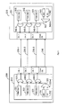
- FIG. 2 shows an exemplary and non-limiting block diagram of a system 200 for transferring signals, for example high definition multimedia signals, over four twisted pairs constructed in accordance with an embodiment of the invention.
- the system 200 transfers high speed multimedia data, a clock, and control data signals between a multimedia source 210 and a multimedia sink 220 over four twisted pairs.
- the multimedia source 210 includes a data multiplexing circuit 211 and a source clock and data handler 212 .
- the multimedia sink 220 comprises a data demultiplexing circuit 221 and a sink clock and data handler 222 .
- the data multiplexing circuit 211 multiplexes high speed multimedia data 251 and low speed data 252 into at most three output signals 253 , 254 , and 255 .
- the three signals are carried over three channels 230 - 1 , 230 - 2 and 230 - 3 from the source 210 to the sink 220 .
- the high speed data 251 includes video, audio, and auxiliary data preferably encapsulated in TMDS characters.
- the high speed data is transferred at a high rate (e.g., 50 Mega Hz) from the multimedia source 210 to multimedia sink 220 .
- channels 230 - 1 , 230 - 2 and 230 - 3 are TMDS channels that transport TMDS characters at a pixel rate which is synchronized with a TMDS clock sent over a channel 240 .
- a pixel rate determines the number pixels transmitted per second and it is typically higher than 25 Mega pixels per second.
- the low speed data 252 comprises configuration, control, management and status information, which is only sent from the multimedia source 210 to the multimedia sink 220 .
- the low-speed data 252 may include SCL, SDA and CEC signals which are typically transferred at a rate (e.g., 500 Kilo Hz) lower than the pixel rate.
- the low speed data 252 will be referred hereinafter as “source-to-sink management data.”
- the data demultiplexing circuit 221 demultiplexes the signals 261 , 262 , and 263 received on channels 230 to produce the source-to-sink management data (e.g., SCL, SDA and CEC signals) on an output 264 and the high speed data on an output 265 .
- the high speed data includes three different multimedia data streams. The operation of the data multiplexing and data demultiplexing circuits 211 and 221 are described in greater detail below.
- the sink clock and data handler 212 and sink clock and data handler 222 together enable transferring, without interference, low speed data in the sink-to-source direction and a clock in the source-to-sink direction over the channel 240 .
- a clock 271 is generated by the multimedia source 210 and transmitted to the multimedia sink 220 over the channel 240 .
- the clock is recovered by the sink clock and data handler 222 which outputs a clock 281 .
- the clock signal 281 is used as a frequency reference for data recovery on the channels 230 .
- the low speed data (hereinafter the “sink-to-source management data”) provided on an input 282 includes at least HDP, SDA and CEC signals transmitted over the channel 240 from the multimedia sink 220 to multimedia source 210 .
- the sink-to-source management data is transferred at a rate which is significantly lower than the rate of clock 271 .
- the source clock and data handler 212 outputs the sink-to-source management data on an output 272 .
- the operation of the source clock and data handler 212 and sink clock and data handler 222 will be described in detail below.
- the high definition multimedia (e.g. HDMI) signals are transported over four channels 230 - 1 , 230 - 2 , 230 - 3 , and 240 .
- Each such channel carries signals over a single twisted-pair.
- only four twisted-pairs are needed to transport the HDMI signals. Therefore, as a standard twisted pair type cable includes four twisted pairs in a single cable jacket, the source video 210 and the sink video 220 can be physically connected using such a cable.
- a twisted pair type cable includes, but is not limited to, Category 5, Category 5e, Category 6, Category 6e, and the likes.
- the transmission of signals between the source video 210 to the sink video 220 is fully compliant with the HDMI standard.
- FIG. 3 shows an exemplary and a non-limiting block diagram of the data multiplexing circuit 211 and data demultiplexing circuit 221 implemented in accordance with an embodiment of the invention.
- the data multiplexing circuit 211 includes four multiplexers 310 - 1 , 310 - 2 , 310 - 3 and 310 - 4 .
- the multiplexer 310 - 4 generates and outputs a source-to-sink management data on an output 333 by multiplexing DDC 331 and CEC 332 signals.
- Each of multiplexers 310 - 1 , 310 - 2 , and 310 - 3 respectively receives one of the high speed data streams 321 , 322 , and 323 as well as the data on output 333 and interleaves a data stream and the source-to-sink management data on a respective channel 230 .
- HDMI interface multimedia data is sent during a video period, audio and auxiliary data is transferred during a data island period, a control code is sent during the remaining blanking period.
- the HDMI standard defines a required minimum duration of a control period and a partial use of specific portions of the control period. The remaining allocated time of the control period is available for transmission of special purpose data.
- the source-to-sink management data 333 is represented as control codes using user-defined semantics.
- the user-defined control codes are transmitted at a high rate during the control period.
- source-to-sink management data as control codes is compatible with all aspects of the HDMI standard.
- An HDMI receiver usually ignores control codes with unknown semantics.
- the user defined control codes can be interpreted by the data demultiplexing circuit 221 .
- the data demultiplexing circuit 221 includes four demultiplexers 340 - 1 , 340 - 2 , 340 - 3 , and 340 - 4 which produce the data streams 351 , 352 , and 353 as well as DDC 361 and CEC 362 signals.
- each of the demultiplexers 340 - 1 , 340 - 2 , and 340 - 3 demultiplexes the respective data stream and the source-to-sink management data from the signals received on channels 230 .
- the DDC 361 and CEC 362 are derived from management data received on input 363 using demultiplexer 340 - 4 .
- the source-to-sink management data is transmitted at a high rate during the control period and pixel data of the multimedia media is sent during the video period, therefore the bandwidth of the transmitted video is not reduced.
- multimedia data is transmitted as defined in the HDMI standard.
- FIG. 4 shows an exemplary and non-limiting block diagram of the handlers 212 and 222 implemented in accordance with an embodiment of the invention.
- the clock sink clock and data handler 222 comprises a multiplexer 410 , a phase-locked loop (PLL) circuit 420 , and a high-pass filter 430 .
- the multiplexer 410 multiplexes the HDP 411 , DDC 412 and CEC 413 signals and outputs, on an output 414 , the sink-to-source management data.
- the output 414 is connected to the channel 240 to transport the sink-to-source management data to multimedia source 210 .
- a clock sent from the source 210 over the channel 240 is fed to the high-pass filter 430 to extract the clock signal.
- the frequency of the clock is significantly higher than the transmission rate of the sink-to-source management data.
- the clock frequency is 50 MHz and the management data transfer rate is 500 kHz. Therefore, the high-pass filter 430 passes only a clock 415 to the PLL circuit 420 , which is used for a clock recovery.
- the source clock and data handler 212 comprises a PLL circuit 450 , a low-pass filter 460 and a demultiplexer 470 .
- the low-pass filter 460 passes only low frequency data, i.e., recovers the sink-to-source management data from the signal carried over the channel 240 .
- the management data is fed to the demultiplexer 470 which outputs three control signals: HDP 481 , DDC 482 , and CEC 483 .
- the PLL circuit 450 generates a clock 484 at a base frequency of a pixel rate.
- the clock 484 is transmitter over the channel 240 to the multimedia sink 210 .
- the circuits 212 and 222 can implement multiplexing/demultiplexing techniques other than the frequency multiplexing/demultiplexing described above. These techniques include, but are not limited to, timing multiplexing/demultiplexing, superposition of signals with echo canceling, and so on.
- FIG. 5 shows an exemplary and a non-limiting flowchart 500 describing a method for transferring signals, for example high definition multimedia signals, over four twisted pairs implemented in accordance with an embodiment of an invention.
- the steps of FIG. 5 may be performed in order or in parallel.
- the high definition multimedia signals comprise TMDS characters, a clock, and control data.
- the control data includes the CEC, DDC, and HPD signals which are transported at a low rate (e.g., 500 kHz).
- the TMDS characters are sent from a multimedia source to a multimedia sink at a high rate (e.g., 50 mega Hz).
- source-to-sink management data is generated by multiplexing DDC and CEC signals that should be sent to the multimedia sink.
- the source-to-sink management data is multiplexed with high speed multimedia data.
- the multiplexed signals are transmitted over three channels (e.g., channels 230 ) at a high speed rate. Each channel carries signals over a single twisted-pair.
- the source-to-sink management data is sent using predefined control codes during the control period of the TMDS transmission.
- a demultiplexing process is performed to recover the DDC and CEC signals as well as the video streams.
- sink-to-source management data is generated by multiplexing DDC, HPD and CEC signals.
- the sink-to-source management data is sent from the multimedia sink to the multimedia source over a fourth channel.
- a clock signal e.g., a TMDS clock
- the source video also over the fourth channel. That is, the fourth channel carries, over a single twisted pair, the clock signal and a sink-to-source management data without interference between them.
- a multiplexing technique including, but not limited to, time multiplexing (e.g., transmitting 10,000 clocks and then freeing the line for data transmission during a period of 100 clock cycles), frequency multiplexing, and superposition of signals with echo canceling.
- the clock signal is recovered at the multimedia sink and the sink-to-source management data is demultiplexed, at the multimedia source, to generate the DDC, HPD and CEC signals.
- the invention has been now described with a reference to a specific embodiment where the disclosed system and method are utilized to transfer HDMI signals over a four twisted pairs.
- other embodiments would be apparent to one of ordinary skill in the art.
- the invention described herein can be easily adopted to transmit signals of other digital display interface standards, such as a digital visual interface (DVI), and the like.
- DVI digital visual interface
- the principles of the invention may be implemented in hardware, software, firmware or any combinations thereof.
- the software may be implemented as an application program tangibly embodied on a program storage unit or computer readable medium.
- the application program may be uploaded to, and executed by, a machine comprising any suitable architecture, for example a computer platform having hardware such as one or more central processing units (“CPU”), a random access memory (“RAM”), and input/output (“I/O”) interfaces.
- CPU central processing units
- RAM random access memory
- I/O input/output
- the computer platform may also include an operating system and microinstruction code.
- the various processes and functions described herein may be either part of the microinstruction code or part of the application program, or any combination thereof, which may be executed by a CPU, whether or not such computer or processor is explicitly shown.
Abstract
Description
Claims (33)
Priority Applications (1)
| Application Number | Priority Date | Filing Date | Title |
|---|---|---|---|
| US12/050,632 US8098690B2 (en) | 2008-03-18 | 2008-03-18 | System and method for transferring high-definition multimedia signals over four twisted-pairs |
Applications Claiming Priority (1)
| Application Number | Priority Date | Filing Date | Title |
|---|---|---|---|
| US12/050,632 US8098690B2 (en) | 2008-03-18 | 2008-03-18 | System and method for transferring high-definition multimedia signals over four twisted-pairs |
Publications (2)
| Publication Number | Publication Date |
|---|---|
| US20090238212A1 US20090238212A1 (en) | 2009-09-24 |
| US8098690B2 true US8098690B2 (en) | 2012-01-17 |
Family
ID=41088873
Family Applications (1)
| Application Number | Title | Priority Date | Filing Date |
|---|---|---|---|
| US12/050,632 Expired - Fee Related US8098690B2 (en) | 2008-03-18 | 2008-03-18 | System and method for transferring high-definition multimedia signals over four twisted-pairs |
Country Status (1)
| Country | Link |
|---|---|
| US (1) | US8098690B2 (en) |
Cited By (2)
| Publication number | Priority date | Publication date | Assignee | Title |
|---|---|---|---|---|
| US20090116547A1 (en) * | 2007-02-07 | 2009-05-07 | Valens Semiconductor Ltd. | Devices for transmitting digital video and data over the same wires |
| TWI548279B (en) * | 2013-08-02 | 2016-09-01 | 宏正自動科技股份有限公司 | Multimedia transceiver system, multimedia transmission apparatus, and multimedia receiving apparatus |
Families Citing this family (9)
| Publication number | Priority date | Publication date | Assignee | Title |
|---|---|---|---|---|
| US20100080305A1 (en) * | 2008-09-26 | 2010-04-01 | Shaori Guo | Devices and Methods of Digital Video and/or Audio Reception and/or Output having Error Detection and/or Concealment Circuitry and Techniques |
| JP5422276B2 (en) * | 2009-07-03 | 2014-02-19 | 日立コンシューマエレクトロニクス株式会社 | Wireless video transmission device |
| US8755431B2 (en) | 2010-01-14 | 2014-06-17 | Silicon Image, Inc. | Transmission and detection of multi-channel signals in reduced channel format |
| TWI457000B (en) | 2010-10-05 | 2014-10-11 | Aten Int Co Ltd | Signal extender system and signal extender and transmitting module and receiving module thereof |
| JP5771986B2 (en) * | 2010-12-28 | 2015-09-02 | ソニー株式会社 | Electronic device, electronic device control method, and electronic device system |
| JP5444310B2 (en) * | 2011-11-17 | 2014-03-19 | 株式会社東芝 | Bidirectional communication interface device, transmission device, and reception device |
| US9087163B2 (en) * | 2012-07-11 | 2015-07-21 | Silicon Image, Inc. | Transmission of multiple protocol data elements via an interface utilizing a data tunnel |
| CN110245114B (en) * | 2019-06-24 | 2021-10-15 | 北京润科通用技术有限公司 | Data processing method and device |
| CN113852448B (en) * | 2021-11-26 | 2022-03-01 | 长芯盛(武汉)科技有限公司 | Device compatible with multiple transmission rates of active cable and method thereof |
Citations (12)
| Publication number | Priority date | Publication date | Assignee | Title |
|---|---|---|---|---|
| US20030169831A1 (en) * | 2002-03-07 | 2003-09-11 | Stmicroelectronics, Inc | Data assisted serial link decoder using oversampling |
| US20060036788A1 (en) | 2002-09-24 | 2006-02-16 | Monster Cable Products, Inc. | HDMI cable interface |
| US7283566B2 (en) * | 2002-06-14 | 2007-10-16 | Silicon Image, Inc. | Method and circuit for generating time stamp data from an embedded-clock audio data stream and a video clock |
| US20070279408A1 (en) | 2006-06-01 | 2007-12-06 | Intersil Corporation | Method and system for data transmission and recovery |
| US7321946B2 (en) | 2004-07-07 | 2008-01-22 | Infocus Corporation | Link extender having equalization circuitry |
| US20080159356A1 (en) * | 2006-12-28 | 2008-07-03 | Samsung Electronics Co., Ltd. | Method and a system for low-rate channel communication in wireless communication systems |
| US20080187028A1 (en) * | 2007-02-07 | 2008-08-07 | Eyran Lida | Method and apparatus for communicating different types of data over a same network |
| US20080250294A1 (en) * | 2006-11-07 | 2008-10-09 | Chiu Ngo | System and method for wireless communication of uncompressed video having a composite frame format |
| US20080247341A1 (en) * | 2007-04-09 | 2008-10-09 | Synerchip Co., Ltd. | Digital video interface with bi-directional half-duplex clock channel used as auxiliary data channel |
| US20080271073A1 (en) * | 2007-04-24 | 2008-10-30 | Samsung Electronics Co., Ltd. | Method of providing key code information and video device thereof |
| US20080288995A1 (en) * | 2007-05-14 | 2008-11-20 | Wael Diab | Method And System For Enabling Video Communication Via Ethernet Utilizing Asymmetrical Physical Layer Operations |
| US20090046690A1 (en) * | 2007-08-16 | 2009-02-19 | Kun-Li Hsieh | High-speed digital interface transceiver and method of supplying bi-directional communication process on high-speed digital interface device |
-
2008
- 2008-03-18 US US12/050,632 patent/US8098690B2/en not_active Expired - Fee Related
Patent Citations (12)
| Publication number | Priority date | Publication date | Assignee | Title |
|---|---|---|---|---|
| US20030169831A1 (en) * | 2002-03-07 | 2003-09-11 | Stmicroelectronics, Inc | Data assisted serial link decoder using oversampling |
| US7283566B2 (en) * | 2002-06-14 | 2007-10-16 | Silicon Image, Inc. | Method and circuit for generating time stamp data from an embedded-clock audio data stream and a video clock |
| US20060036788A1 (en) | 2002-09-24 | 2006-02-16 | Monster Cable Products, Inc. | HDMI cable interface |
| US7321946B2 (en) | 2004-07-07 | 2008-01-22 | Infocus Corporation | Link extender having equalization circuitry |
| US20070279408A1 (en) | 2006-06-01 | 2007-12-06 | Intersil Corporation | Method and system for data transmission and recovery |
| US20080250294A1 (en) * | 2006-11-07 | 2008-10-09 | Chiu Ngo | System and method for wireless communication of uncompressed video having a composite frame format |
| US20080159356A1 (en) * | 2006-12-28 | 2008-07-03 | Samsung Electronics Co., Ltd. | Method and a system for low-rate channel communication in wireless communication systems |
| US20080187028A1 (en) * | 2007-02-07 | 2008-08-07 | Eyran Lida | Method and apparatus for communicating different types of data over a same network |
| US20080247341A1 (en) * | 2007-04-09 | 2008-10-09 | Synerchip Co., Ltd. | Digital video interface with bi-directional half-duplex clock channel used as auxiliary data channel |
| US20080271073A1 (en) * | 2007-04-24 | 2008-10-30 | Samsung Electronics Co., Ltd. | Method of providing key code information and video device thereof |
| US20080288995A1 (en) * | 2007-05-14 | 2008-11-20 | Wael Diab | Method And System For Enabling Video Communication Via Ethernet Utilizing Asymmetrical Physical Layer Operations |
| US20090046690A1 (en) * | 2007-08-16 | 2009-02-19 | Kun-Li Hsieh | High-speed digital interface transceiver and method of supplying bi-directional communication process on high-speed digital interface device |
Cited By (10)
| Publication number | Priority date | Publication date | Assignee | Title |
|---|---|---|---|---|
| US20090116547A1 (en) * | 2007-02-07 | 2009-05-07 | Valens Semiconductor Ltd. | Devices for transmitting digital video and data over the same wires |
| US20090116583A1 (en) * | 2007-02-07 | 2009-05-07 | Valens Semiconductor Ltd. | HDMI communication over twisted pairs |
| US20090115911A1 (en) * | 2007-02-07 | 2009-05-07 | Valens Semiconductor Ltd. | Methods for transmitting digital multimedia and data over the same wires |
| US20090147864A1 (en) * | 2007-02-07 | 2009-06-11 | Valens Semiconductor Ltd. | HDMI communication over twisted pairs |
| US8503489B2 (en) * | 2007-02-07 | 2013-08-06 | Valens Semiconductor Ltd. | Devices for transmitting digital video and data over the same wires |
| US8565337B2 (en) | 2007-02-07 | 2013-10-22 | Valens Semiconductor Ltd. | Devices for transmitting digital video and data over the same wires |
| US8804775B2 (en) | 2007-02-07 | 2014-08-12 | Valens Semiconductor Ltd. | Method and device for transmitting digital video and data over the same wires |
| US9215059B2 (en) | 2007-02-07 | 2015-12-15 | Valens Semiconductor Ltd. | Transmitting digital video and data over the same wires |
| US9398240B2 (en) | 2007-02-07 | 2016-07-19 | Valens Semiconductor Ltd. | HDMI communication over twisted pairs |
| TWI548279B (en) * | 2013-08-02 | 2016-09-01 | 宏正自動科技股份有限公司 | Multimedia transceiver system, multimedia transmission apparatus, and multimedia receiving apparatus |
Also Published As
| Publication number | Publication date |
|---|---|
| US20090238212A1 (en) | 2009-09-24 |
Similar Documents
| Publication | Publication Date | Title |
|---|---|---|
| US8098690B2 (en) | System and method for transferring high-definition multimedia signals over four twisted-pairs | |
| KR101492535B1 (en) | Method, apparatus and system for generating and facilitating mobile high-definition multimedia interface | |
| US10459674B2 (en) | Apparatus and methods for packing and transporting raw data | |
| US8457153B2 (en) | HDMI-SFP+ adapter/extender | |
| US7356051B2 (en) | Digital visual interface with audio and auxiliary data cross reference to related applications | |
| US20070279408A1 (en) | Method and system for data transmission and recovery | |
| JP4743196B2 (en) | Electronic device and loop determination method in electronic device | |
| US20070242062A1 (en) | EDID pass through via serial channel | |
| KR102344545B1 (en) | Image processing apparatus and control method thereof | |
| WO2017032081A1 (en) | Audio and video playback device, data display method, and storage medium | |
| JP2007228606A (en) | Parallel interface bus communicating video data encoded for serial data link | |
| CN101727873A (en) | Signal conversion apparatuses and display system | |
| US20110013772A1 (en) | Method and Apparatus for Fast Switching Between Source Multimedia Devices | |
| KR20100020952A (en) | Data transmission apparatus with information skew and redundant control information and method | |
| US20140016034A1 (en) | High definition video extender and method | |
| TW201711479A (en) | Multimedia signal transmission device and transmission method thereof | |
| JP2009047698A (en) | Apparatus and method for measuring skew between channels in serial data communication | |
| US9559882B2 (en) | Apparatus and methods for flexible provision of control data in large data structures | |
| EP1231796A2 (en) | System and method for increased data capacity of a digital video link | |
| TW200929919A (en) | Display signal extender and a method of transmitting display signal by using the same | |
| TWI621357B (en) | Method, apparatus and system for communicating sideband data with non-compressed video | |
| CN113225509B (en) | Device and method for converting CEDS video format signal into HDMI interface signal | |
| KR101599356B1 (en) | Displayport to hdmi converter and converting method | |
| CN203313333U (en) | Digital television receiver compatible with multiple data connection interfaces | |
| KR101292782B1 (en) | Transmission apparatus for compositing signal included of hdmi signal and usb signal and method therefor |
Legal Events
| Date | Code | Title | Description |
|---|---|---|---|
| AS | Assignment |
Owner name: TRANSWITCH CORPORATION, CONNECTICUT Free format text: ASSIGNMENT OF ASSIGNORS INTEREST;ASSIGNORS:ROETHIG, WOLFGANG;BAR-NIV, AMIR;REEL/FRAME:020668/0521;SIGNING DATES FROM 20080306 TO 20080310 Owner name: TRANSWITCH CORPORATION, CONNECTICUT Free format text: ASSIGNMENT OF ASSIGNORS INTEREST;ASSIGNORS:ROETHIG, WOLFGANG;BAR-NIV, AMIR;SIGNING DATES FROM 20080306 TO 20080310;REEL/FRAME:020668/0521 |
|
| STCF | Information on status: patent grant |
Free format text: PATENTED CASE |
|
| AS | Assignment |
Owner name: CADENCE DESIGN SYSTEMS, INC., CALIFORNIA Free format text: ASSIGNMENT OF ASSIGNORS INTEREST;ASSIGNOR:TRANSWITCH CORPORATION;REEL/FRAME:033770/0982 Effective date: 20140203 |
|
| FEPP | Fee payment procedure |
Free format text: PAT HOLDER NO LONGER CLAIMS SMALL ENTITY STATUS, ENTITY STATUS SET TO UNDISCOUNTED (ORIGINAL EVENT CODE: STOL); ENTITY STATUS OF PATENT OWNER: LARGE ENTITY |
|
| FEPP | Fee payment procedure |
Free format text: PAYOR NUMBER ASSIGNED (ORIGINAL EVENT CODE: ASPN); ENTITY STATUS OF PATENT OWNER: LARGE ENTITY |
|
| FPAY | Fee payment |
Year of fee payment: 4 |
|
| FEPP | Fee payment procedure |
Free format text: MAINTENANCE FEE REMINDER MAILED (ORIGINAL EVENT CODE: REM.); ENTITY STATUS OF PATENT OWNER: LARGE ENTITY |
|
| LAPS | Lapse for failure to pay maintenance fees |
Free format text: PATENT EXPIRED FOR FAILURE TO PAY MAINTENANCE FEES (ORIGINAL EVENT CODE: EXP.); ENTITY STATUS OF PATENT OWNER: LARGE ENTITY |
|
| STCH | Information on status: patent discontinuation |
Free format text: PATENT EXPIRED DUE TO NONPAYMENT OF MAINTENANCE FEES UNDER 37 CFR 1.362 |
|
| FP | Lapsed due to failure to pay maintenance fee |
Effective date: 20200117 |