EP1890096B1 - Accumulator of air conditioner - Google Patents
Accumulator of air conditioner Download PDFInfo
- Publication number
- EP1890096B1 EP1890096B1 EP07016164.1A EP07016164A EP1890096B1 EP 1890096 B1 EP1890096 B1 EP 1890096B1 EP 07016164 A EP07016164 A EP 07016164A EP 1890096 B1 EP1890096 B1 EP 1890096B1
- Authority
- EP
- European Patent Office
- Prior art keywords
- coolant
- pipe
- accumulator
- air conditioner
- tank
- Prior art date
- Legal status (The legal status is an assumption and is not a legal conclusion. Google has not performed a legal analysis and makes no representation as to the accuracy of the status listed.)
- Active
Links
Images







Classifications
-
- F—MECHANICAL ENGINEERING; LIGHTING; HEATING; WEAPONS; BLASTING
- F25—REFRIGERATION OR COOLING; COMBINED HEATING AND REFRIGERATION SYSTEMS; HEAT PUMP SYSTEMS; MANUFACTURE OR STORAGE OF ICE; LIQUEFACTION SOLIDIFICATION OF GASES
- F25B—REFRIGERATION MACHINES, PLANTS OR SYSTEMS; COMBINED HEATING AND REFRIGERATION SYSTEMS; HEAT PUMP SYSTEMS
- F25B43/00—Arrangements for separating or purifying gases or liquids; Arrangements for vaporising the residuum of liquid refrigerant, e.g. by heat
-
- F—MECHANICAL ENGINEERING; LIGHTING; HEATING; WEAPONS; BLASTING
- F25—REFRIGERATION OR COOLING; COMBINED HEATING AND REFRIGERATION SYSTEMS; HEAT PUMP SYSTEMS; MANUFACTURE OR STORAGE OF ICE; LIQUEFACTION SOLIDIFICATION OF GASES
- F25B—REFRIGERATION MACHINES, PLANTS OR SYSTEMS; COMBINED HEATING AND REFRIGERATION SYSTEMS; HEAT PUMP SYSTEMS
- F25B43/00—Arrangements for separating or purifying gases or liquids; Arrangements for vaporising the residuum of liquid refrigerant, e.g. by heat
- F25B43/006—Accumulators
-
- F—MECHANICAL ENGINEERING; LIGHTING; HEATING; WEAPONS; BLASTING
- F25—REFRIGERATION OR COOLING; COMBINED HEATING AND REFRIGERATION SYSTEMS; HEAT PUMP SYSTEMS; MANUFACTURE OR STORAGE OF ICE; LIQUEFACTION SOLIDIFICATION OF GASES
- F25B—REFRIGERATION MACHINES, PLANTS OR SYSTEMS; COMBINED HEATING AND REFRIGERATION SYSTEMS; HEAT PUMP SYSTEMS
- F25B2400/00—Component parts or details not otherwise provided for in this subclass
- F25B2400/03—Suction accumulators with deflectors
Definitions
- the present invention relates to an accumulator of an air conditioner, and more particularly, to an accumulator of an air conditioner that can be formed of a small tank, so that it can be easily mounted in a small space and is improved in vapor-liquid separating performance with high pressure resistance.
- an air-conditioning cycle is formed by a coolant circulating through the compressor, condenser, throttle valve, and evaporator, and an air-conditioning cycle with a coolant that is compressed at a supercritical pressure above a critical pressure by the compressor is called a supercritical air-conditioning cycle.
- a coolant does not change phase in heat-discharging process into the atmosphere; therefore, a heat discharger for this process is called a gas cooler, not a condenser.
- An air conditioner having the supercritical air-conditioning cycle is, as shown in FIG. 1 , a system including a compressor 1, a condenser 2 (gas cooler), a throttle valve 3, an evaporator 4, from which the air-conditioning cycle is completed, an accumulator 5 that separates the coolant out of the evaporator into gas and liquid, and an internal heat exchanger 6 that causes a heat exchange between the coolant out of the condenser 2 (gas cooler) and the coolant out of the accumulator 5.
- a coolant that flows through a coolant inlet pipe 11 into the upper space inside a tank 12 passes through a section plate 13 and is then separated into oil, a liquid coolant, and a gas coolant, depending on the specific gravity. Only the gas coolant flows through a gas coolant inlet 14a of a coolant pipe 14 in the tank 12 into the coolant pipe and is sent to the compressor 1 through a gas coolant outlet 14b of the coolant pipe 14, which prevents liquid back.
- the coolant pipe 14 has a pipe line that is bent down from the gas coolant inlet 14a under the section pipe 13, extends to the gas coolant outlet 14b above the tank 12.
- An oil return hole 14c is formed at the lower portion inside the tank 12 to allow the oil for the compressor (oil separated from the coolant) to flow into and circulate through the coolant pipe 14.
- JP 11 278045 A describes an accumulator to make a compressor aspirate a gas refrigerant by separating gas and liquid of the refrigerant is arranged between the output side of an evaporator and the compressor, a liquid output passage to make the compressor aspirate a liquid refrigerant to be reserved in the inside of this accumulator is provided, opening of a throttle passage provided in this liquid output passage is reduced at the time of a cooling mode by a valve mechanism and increased at the time of a heating mode.
- US 4 651 540 A describes a suction accumulator including a casing for defining a liquid storage vessel.
- the casing includes an upper and lower end cap.
- a baffle is disposed in a upper portion of the casing adjacent the upper end cap whereby refrigerant flowing into the inlet will be deflected by the baffle from an axial entry direction to flow in a horizontal plane and will be confined by the baffle until the fluid flows generally tangentally to the casing wall. At this point, the fluid leaves the baffle and flows into the liquid storage vessel.
- An elongated conduit is disposed in the casing whereby gaseous refrigerant flows through a tortuous path to enter the conduit and then flows through the conduit to the fluid outlet of the suction accumulator.
- US 4 827 725 A describes a suction accumulator for the compressor of a refrigeration system in which a vertical fluid storage vessel comprises a cylindrical central member and a lower end cap.
- a disk-shaped dirt trap baffle member includes at its outer periphery a plurality of circumferentially spaced tabs that are clamped between the central housing member and lower end cap. Circumferentially intermediate the tabs are gaps through which liquid refrigant flows from an active zone above the baffle to a quiet zone therebelow. Within the quiet zone, liquid refrigerant flows from a radially outer region to a radially inner region along a tortuous flow part created by a vertically extending wall comprising a portion of the baffle member.
- a bleed-through orifice in a gaseous refrigerant flow conduit siphons liquid refrigerant from the radially inner region into the gaseous flow path.
- US 4 199 960 A describes an accumulator for receiving a mixture of gaseous and liquid refrigerant fluid and liquid oil from an evaporator in an air conditioning system and for delivering only gaseous refrigerant fluid with oil atomized therein to the compressor.
- the accumulator has radially spaced telescoped straight lengths of tube to conduct the gaseous refrigerant fluid with oil atomized therein from the interior of the accumulator to the exterior thereof to thus eliminate the conventional U-shaped tube for this purpose whereby the diameter of the accumulator may be smaller than the diameter needed to accommodate a U-shaped tube.
- the inner one of the telescoped tubes conducts gaseous refrigerant fluid from the top of the accumulator to the bottom end of the outer telescoped tube where it picks up oil from the bottom of the accumulator through a bleed port through the wall of the outer tube and then passes unwardly between the tubes to an outlet port at the top of the accumulator.
- US 2002/083733 A1 describes an accumulator with an internal heat exchanger for use in an air conditioning or refrigeration system having a compressor, a condenser, an expansion device, and an evaporator is disclosed.
- the heat exchanger comprises a tube having at least one high temperature channel and one low temperature channel extending through the interior of the tube.
- US 6 681 597 B1 describes an integrated unit in a refrigeration system wherein a low-pressure conduit and high-pressure conduit are in conductive heat exchange relation to each other within an accumulator housing.
- the low pressure conduit and high-pressure conduit may be flat tubes wherein broad sides of the flat tubes are in conductive heat exchange relation to each other.
- the low-pressure conduit and high-pressure conduit or tubes have longitudinal axes that extend parallel to one another over a length within the integrated unit.
- an object of the present invention is to provide an accumulator of an air conditioner that can be formed of a small tank, so that it can be easily mounted in a small space and is improved in vapor-liquid separating performance with high pressure resistance.
- Another object of the invention is to provide a compact-sized air-conditioning system including the functions of an internal heat exchanger that makes heat exchange between a high-temperature high-pressure side and a low-temperature low-pressure side by fitting high-pressure pipes with each other in the longitudinal direction of a dual pipe such that the internal heat exchange can be integrally provided in an accumulator.
- an accumulator of an air conditioner according to the invention includes all the technical features of the independent claim 1.
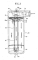
- FIG. 3 is a view showing the configuration of an accumulator of an air conditioner according to a first embodiment of the invention.
- a section plate 32 is disposed at the upper portion inside a tank 20
- an upper body 34 with a coolant intake 34a that allows a coolant to flow into the upper portion inside the tank is combined to the upper end of the tank 20, and a dual pipe 36 is vertically disposed under the inside bottom of the upper body 34 in the tank 20 to discharge a gas coolant separated from the coolant inside the tank.
- a lower part 24 of the tank is combined to a tank body 22 by welding etc. or the lower part 24 of the tank is integrally formed with the tank body 22 by forging and combined with the upper body 34.
- An explosion means 38 with an explosion plate that explodes under a predetermined pressure to rapidly discharge a coolant outside at an abnormal high pressure is provided at the bottom of the lower part 24 of the tank.
- a side protrusion 44 with a hole for a coolant to flow inside is formed on the outside of a cylinder 42.
- a hole that forms the coolant intake 34a is formed at the side of the side protrusion 44 to easily separate liquid and vapor from the coolant that flows into the upper portion inside the tank 20 by guiding the coolant such that it flows inside while circumferentially rotating.
- a protrusion 46 with a round side 46a is formed at the bottom of the upper body 34 where an internal pipe of the dual pipe 36 (described below) is connected, in order to easily induce a cyclone by allowing the coolant that flows into the tank through the coolant intake 34a to hit the round side and easily rotate.
- a gas coolant outlet 36b through which a gas coolant separated from the coolant in the tank is discharged is formed at the center of the protrusion 46.
- FIG. 5 is a perspective view showing an example in which the dual pipe 36 is connected to the inside bottom of the upper body 34. As shown in FIG. 5 , the internal pipe of the dual pipe 36 (described below) is communicated with the gas coolant outlet 36b of the upper body 34 through the protrusion 46.
- an upper body 134 that is combined to the upper end of the tank 20 may be formed of a cylindrical block of a predetermined thickness.
- a coolant intake 134a that allows a coolant to flow into the tank 20 and a gas coolant outlet 136b through which a gas coolant is discharged from the inside of the tank are vertically formed through the upper body 134 of cylindrical block.
- the section plate 32 is disposed in contact with the lower end of the upper body 34 or fitted on the internal pipe of the dual pipe 36 at a predetermined distance from the upper body 134.
- a plurality of long groove-shaped holes 32a is circumferentially formed through the section plate 32 to allow a coolant to flow down into the tank 20.
- a small filter (not shown) is provided on the plane (generally upper surface) of the section plate 32 and fixed by ring-shaped clips 48, 49 that are fitted on the outer and inner circumferences of the section plate 32, respectively.
- the dual pipe 36 is a pipe with an internal pipe 52 that is communicated with the gas coolant outlets 36b, 136b and an external pipe 54 that is connected to a gas coolant inlet 36a.
- a return cap 56 is combined to the lower end of the dual pipe 36 and the gas coolant flows from the upper portion inside the tank 20 into the gas coolant inlet 36a between the internal pipe 52 and the external pipe 54, turns into the internal pipe 52 at the return cap 56, and continues flowing to an outer pipe through the gas coolant outlets 36b, 136b.
- the coolant intakes 34a, 134a are formed above the section plate 32, the gas coolant inlet 36a is formed under the section pipe 32, and a liquid coolant block pipe 58 that surrounds the gas coolant inlet 36a to prevent the liquid coolant from flowing into the coolant outlet pipe (dual pipe) through the gas coolant inlet 36a is combined to the lower surface of the section plate 32.
- the liquid coolant block pipe 58 is a cone-shaped pipe with the top cut and the lower end open, or as shown in FIG. 8 , may be a liquid coolant block pipe 158 that is a cylindrical pipe with the lower end open.
- the liquid coolant block pipes 58, 158 are fixed by the ring-shaped clip 49 or other specific fixing means.
- the passage area defined by a gap c between the liquid coolant block pipes 58, 158 and the external pipe 54 of the coolant outlet pipe (dual pipe) is larger than the passage area between the internal pipe 52 and the external pipe 54 of the coolant outlet pipe.
- the dual pipe 36 is an extruded dual pipe with the internal pipe 52 and external pipe 54 that are integrally formed, or the internal pipe 52 and the external pipe 54 may be formed by combining a separate internal pipe and external pipe.
- the coolant intake 134a may extend down through the section plate 32 by an inlet pipe 62 and the gas coolant inlet 36a may be formed above the section plate 32.
- the coolant intake 34a (shown in FIG. 5 ) may extend to the upper portion of the section plate 32 by an inclined inlet pipe 162, in which the protrusion 46 shown in FIG. 5 is not needed and the other configuration is the same as in FIGS. 3 and 5 .
- FIG. 11 is a cross-sectional view showing the lower part 24 of the tank in which the return cap 56 is disposed. As shown in FIG. 11 , an oil return hole 56a is formed through the return cap 56 to allow the oil for the compressor (oil separated from the coolant) to flow into and circulate through the coolant outlet pipe (dual pipe).
- the internal pipe 52 of the dual pipe 36 extends down more than the external pipe 54 to allow the oil to easily flow into the internal pipe 52.
- a filter 64 is provided over the return cap 56 to prevent any foreign substances from flowing into the internal pipe 52 through the oil return hole 56a.
- a filter 66 may be provided at the lower end of the internal pipe 52.
- the oil that has flowed in the tank 20 is separated in to oil, a liquid coolant, and a gas coolant from the bottom of the tank and it is preferable to form the bottom of the tank under the return cap 56 deeper than other portions to easily collect and return the oil, in which the explosion means 38 shown in FIG. 3 is combined with the higher portion of the bottom of the tank.
- the explosion means 38 is composed of an explosion plate 38a fixed to the bottom of the tank, a housing 38b of a vertical pipe and a horizontal pipe 38c that are sequentially connected to the explosion plate 38a.
- the explosion plate 38a is disposed between the machined surface of the lower part 24 of the tank and the housing 38b of vertical pipe.
- the accumulator it is preferable for the accumulator to increase the diameter of the tank to increase capacity; however, it is strongly required to reduce the outer diameter of the tank because it is restricted by space in a small space, such as an engine room of a vehicle, and it is needed to improve liquid-vapor separating performance and pressure resistance in the tank of a accumulator of a small diameter to solve the above-mentioned problems.
- the tank of an accumulator requires larger capacity than a liquid receiver, so that the diameter of the tank is usually set at 60 mm or more.
- FIG. 14 shows a graph illustrating liquid-vapor separating performance to the diameter of the tank equipped with a dual pipe according to the embodiment of the invention
- FIG. 15 shows a graph illustrating pressure resistance to the diameter of the tank equipped with a dual pipe according to the embodiment.
- a region of a liquid coolant under normal operating condition appears when the ratio of a liquid coolant in the tank of the accumulator to the entire inside volume is 0.65 in a common liquid-vapor separating tank.
- the amount of liquid coolant in the liquid-vapor separating tank that is needed in an air conditioner is at a minimum 250 cc to a maximum 800 cc, it can be seen from the graph that the liquid-vapor separating performance is good when the diameters are in the range of 30 mm to 60 mm.
- An accumulator of an air conditioner according to a second embodiment of the invention has an integral internal heat exchanger.
- the accumulator of an air conditioner according to the first embodiment of the invention does not include an internal heat exchanger, but the accumulator of an air conditioner according to this embodiment of the invention includes an additional mechanism that flows a coolant for internal heat exchange into the tank and circulates it therein.
- the coolant for internal heat exchange in order to distinguish the coolant for internal heat exchange from the coolant that is separated into a liquid and a gas through the coolant outlet pipe, the coolant for internal heat exchange is referred to as a 'high-pressure coolant' and the coolant that is separated into a liquid and a gas through the coolant outlet pipe is referred to as a 'low-pressure coolant'.
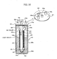
- a low-pressure coolant inlet pipe 322 through which a low-pressure coolant flows is disposed at the upper portion inside a hollow tank 320 and a low-pressure coolant outlet pipe 324 is vertically disposed at the center inside the tank 320 to discharge a gas coolant separated from the coolant that has flowed in the tank.
- the high-pressure coolant inlet pipe 326 longitudinally covers a part of the outside of the low-pressure coolant outlet pipe 324 for heat exchange with the low-pressure coolant
- a high-pressure coolant outlet pipe 328 longitudinally covers the other part of the outside of the low-pressure coolant outlet pipe 324 for heat exchange with the low-pressure coolant while being communicated with the lower end of the high-pressure coolant inlet pipe 326.
- the tank 320 is composed of a tank body 320a and a lower part 320b of the tank combined to the lower portion of the tank body 320a, or the tank body 320a and the lower part 320b of the tank may be integrally formed by forging and an upper body 321 is combined to the upper end of the tank body 320a.
- the tank 320 may be composed of the tank body 320a and the lower part 320b of the tank that are integrally formed.
- the low-pressure coolant inlet pipe 322 is disposed with the upper portion passing through the upper body 321 and the outside of the lower portion having coolant injection hole 322a to inject a coolant to the high-pressure coolant inlet pipe 326, the high-pressure coolant outlet pipe 328, or the inside of the tank 320 and improve liquid-vapor separating performance while the injected coolant rotates.
- the low-pressure outlet pipe 324 is a dual pipe with an internal pipe 324a and an external pipe 324b and a return cap 330 is combined to the lower end of the dual pipe. Accordingly, a gas coolant flows from the upper portion inside the tank 320 through a gas coolant inlet E1 between the internal pipe 324a and the external pipe 324b and turns into the internal pipe 324a at the return cap 330.
- the upper and lower portions of the internal pipe 324a extends more than the upper and lower ends of the external pipe 324b and the upper end of the internal pipe 324a is positioned through the upper body 321.
- the gas coolant inlet E1 is formed under the upper body 321.
- the low-pressure coolant outlet pipe 324 is an extruded dual pipe with the internal pipe 324a and the external pipe 324b that are integrally formed, or the internal pipe and the external pipe are formed by combining separate internal pipe with external pipe.
- the high-pressure coolant inlet pipe 326 has an inlet 326a that is positioned through the upper body 321 and a heat exchanging portion 326b through which heat is exchanged with a low-pressure coolant in the tank 320.
- the high-pressure coolant outlet pipe 328 has an outlet 328a that is positioned through the upper body 321 and a heat exchanging portion 328b through which heat is exchanged with the low-pressure coolant in the tank 320.
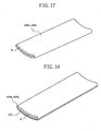
- the heat exchanging portions 326b, 328b of the high-pressure coolant inlet pipe 326 and the high-pressure coolant outlet pipe 328 are each formed of a thin tube that is curved in the width,direction and has a plurality of coolant passages H inside.
- the heat exchanging portions 326b, 328b are curved in an arc shape.
- the inlet 326a of the high-pressure coolant inlet pipe 326 and the outlet 328a of the high-pressure coolant outlet pipe 328 are each formed of one coolant passage, and the inlet 326a and the outlet 328a are communicated with corresponding heat exchanging portions 326b, 328b formed of a plurality of coolant passages.
- the curved thin tube (heat exchanging portions 326b, 328b) is formed in a curved thin tube shape by extrusion without a post-machining.
- the outsides of the high-pressure coolant pipes 326, 328 and the low-pressure coolant outlet pipe 324 are joined and arranged such that the coolants in the high-pressure coolant pipes 326, 328 exchange heat with the coolant in the low-pressure coolant outlet pipe 324.
- Heat conductive fins 332 are provided on the outside of the curved thin tube (heat exchanging portions 326b, 328b) to increase heat exchange efficiency.
- connection cap 334 may be integrally formed with the return cap 330.
- An oil return hole 330a is formed through the return cap 330 to allow the oil for the compressor (oil separated from the coolant) to flow into and circulate through the internal pipe 324a of the low-pressure coolant outlet pipe 324.
- a filter (not shown) may be provided over the return cap 330 to prevent any foreign substances to flow inside through the oil return hole 330a.
- FIG. 18 shows another embodiment of the heat exchanging portion of the high-pressure coolant inlet pipe 326 and the high-pressure coolant outlet pipe 328 of the invention.
- Protruding heat conductive fins 432 are integrally formed, on the curved outside, with heat exchanging portions 426b, 428b of this embodiment.
- FIG. 19 shows another embodiment of the heat exchanging portion of the high-pressure coolant inlet pipe 326 and the high-pressure coolant outlet pipe 328 of the invention.
- Individual heat conductive fins 532 of offset fins with folds are attached to the curved outside of heat exchanging portions 526b, 528b of the invention.
- the heat conductive fins 532 of offset fins with folds increases the heat exchange rate by increasing the heat exchange area.
- a low-pressure coolant that flows from the evaporator 4 (shown in FIG. 1 ) into the upper portion inside the tank 320 through the low-pressure coolant inlet pipe 322 is separated into oil, a liquid coolant, and a gas coolant while flowing down.
- the liquid-vapor separating performance is increased by injecting the coolant through the coolant injection hole 322a to the high-pressure coolant inlet pipe 326, the high-pressure coolant outlet pipe 328, or the inside of the tank 320.
- the separated gas coolant flows inside through the gas coolant inlet E1 between the internal pipe 324a and external pipe 324b of the low-pressure coolant outlet pipe 324, turns up into the internal pipe 324a at the return cap 330, and then continues flowing to the outer pipe toward the compressor 1 (shown in FIG. 1 ).
- the stagnant oil for the compressor at the lower portion in the tank 320 returns to the compressor through the oil return hole 330a.
- the high-pressure coolant that flows from the condenser 2 (gas cooler) (shown in FIG. 1 ) into the high-pressure coolant inlet pipe 326 exchanges heat with the gas coolant in the low-pressure coolant outlet pipe 324 and the low-pressure coolant in the tank 320 while passing through the heat exchanging portion 326b, exchanges heat with the gas coolant in the low-pressure outlet pipe 324 and the low-pressure coolant in the tank 320 while passing through the heat exchanging portion 328b of the high-pressure coolant outlet pipe 328 across the connection cap 334, and then continues flowing through the outlet 328a of the high-pressure coolant outlet pipe 328 to the outer pipe toward the throttle valve 3 (shown in FIG. 1 ).
- An accumulator of an air conditioner according to an embodiment of the invention can be formed of a small tank, so that it can be easily mounted in a small space and is improved in vapor-liquid separating performance with high pressure resistance.
- an internal heat exchanger is integrally provided in the accumulator, such that system efficiency is increased by increase in heat exchange efficiency inside the body of the accumulator. Further, the internal heat exchanger is integrally provided without providing a specific internal heat exchanger outside, such that the coolant inlet and outlet are formed at the upper portion of the body of the accumulator and piping is easy.
Landscapes
- Engineering & Computer Science (AREA)
- Chemical & Material Sciences (AREA)
- Analytical Chemistry (AREA)
- Power Engineering (AREA)
- Physics & Mathematics (AREA)
- Mechanical Engineering (AREA)
- Thermal Sciences (AREA)
- General Engineering & Computer Science (AREA)
- Air-Conditioning For Vehicles (AREA)
- Heat-Exchange Devices With Radiators And Conduit Assemblies (AREA)
Description
- The present invention relates to an accumulator of an air conditioner, and more particularly, to an accumulator of an air conditioner that can be formed of a small tank, so that it can be easily mounted in a small space and is improved in vapor-liquid separating performance with high pressure resistance.
- In general, in an air conditioner for air-conditioning of a vehicle, an air-conditioning cycle is formed by a coolant circulating through the compressor, condenser, throttle valve, and evaporator, and an air-conditioning cycle with a coolant that is compressed at a supercritical pressure above a critical pressure by the compressor is called a supercritical air-conditioning cycle. In general, in supercritical air-conditioning cycles, a coolant does not change phase in heat-discharging process into the atmosphere; therefore, a heat discharger for this process is called a gas cooler, not a condenser.
- In these supercritical air-conditioning cycles, because it is difficult for the coolant discharged out of the evaporator to form superheat due to the characteristics of the coolant, liquid coolant flows into the compressor, which causes liquid back and damage to the condenser. In order to prevent these problems, an accumulator is provided to separate liquid and vapor, and then send only the gas coolant to the condenser.
- An air conditioner having the supercritical air-conditioning cycle is, as shown in
FIG. 1 , a system including acompressor 1, a condenser 2 (gas cooler), athrottle valve 3, an evaporator 4, from which the air-conditioning cycle is completed, anaccumulator 5 that separates the coolant out of the evaporator into gas and liquid, and aninternal heat exchanger 6 that causes a heat exchange between the coolant out of the condenser 2 (gas cooler) and the coolant out of theaccumulator 5. - According to the
accumulator 5 in the related art, as shown inFIG. 2 , a coolant that flows through acoolant inlet pipe 11 into the upper space inside atank 12 passes through asection plate 13 and is then separated into oil, a liquid coolant, and a gas coolant, depending on the specific gravity. Only the gas coolant flows through agas coolant inlet 14a of acoolant pipe 14 in thetank 12 into the coolant pipe and is sent to thecompressor 1 through agas coolant outlet 14b of thecoolant pipe 14, which prevents liquid back. - The
coolant pipe 14 has a pipe line that is bent down from thegas coolant inlet 14a under thesection pipe 13, extends to thegas coolant outlet 14b above thetank 12. Anoil return hole 14c is formed at the lower portion inside thetank 12 to allow the oil for the compressor (oil separated from the coolant) to flow into and circulate through thecoolant pipe 14. - However, in the accumulator in an air-conditioner in the related art, it is required to keep the size of the tank larger than a predetermined size because a part of the coolant pipe bends according to the pipe line of the coolant pipe provided inside the tank. Therefore, a predetermined-sized space should be ensured in the engine room of a vehicle to mount the accumulator in the vehicle, which causes a problem when mounting in a small space.
- In order to overcome the problems, a structure in which an inlet pipe is formed at the upper portion of a tank and a gas coolant outlet of a coolant pipe is formed at the lower portion of the tank has been proposed; however, the accumulator having the above structure relatively required more bending and length for a counter pipe outside the tank.
- Further, it was difficult to achieve high efficiency in separation, because a fluid (coolant) composed of oil, a liquid coolant, and a gas coolant was separated by only depending on the specific gravity.
-
JP 11 278045 A -
US 4 651 540 A describes a suction accumulator including a casing for defining a liquid storage vessel. The casing includes an upper and lower end cap. A baffle is disposed in a upper portion of the casing adjacent the upper end cap whereby refrigerant flowing into the inlet will be deflected by the baffle from an axial entry direction to flow in a horizontal plane and will be confined by the baffle until the fluid flows generally tangentally to the casing wall. At this point, the fluid leaves the baffle and flows into the liquid storage vessel. An elongated conduit is disposed in the casing whereby gaseous refrigerant flows through a tortuous path to enter the conduit and then flows through the conduit to the fluid outlet of the suction accumulator. -
US 4 827 725 A describes a suction accumulator for the compressor of a refrigeration system is disclosed in which a vertical fluid storage vessel comprises a cylindrical central member and a lower end cap. A disk-shaped dirt trap baffle member includes at its outer periphery a plurality of circumferentially spaced tabs that are clamped between the central housing member and lower end cap. Circumferentially intermediate the tabs are gaps through which liquid refrigant flows from an active zone above the baffle to a quiet zone therebelow. Within the quiet zone, liquid refrigerant flows from a radially outer region to a radially inner region along a tortuous flow part created by a vertically extending wall comprising a portion of the baffle member. A bleed-through orifice in a gaseous refrigerant flow conduit siphons liquid refrigerant from the radially inner region into the gaseous flow path. -
US 4 199 960 A describes an accumulator for receiving a mixture of gaseous and liquid refrigerant fluid and liquid oil from an evaporator in an air conditioning system and for delivering only gaseous refrigerant fluid with oil atomized therein to the compressor. The accumulator has radially spaced telescoped straight lengths of tube to conduct the gaseous refrigerant fluid with oil atomized therein from the interior of the accumulator to the exterior thereof to thus eliminate the conventional U-shaped tube for this purpose whereby the diameter of the accumulator may be smaller than the diameter needed to accommodate a U-shaped tube. The inner one of the telescoped tubes conducts gaseous refrigerant fluid from the top of the accumulator to the bottom end of the outer telescoped tube where it picks up oil from the bottom of the accumulator through a bleed port through the wall of the outer tube and then passes unwardly between the tubes to an outlet port at the top of the accumulator. -
US 2002/083733 A1 describes an accumulator with an internal heat exchanger for use in an air conditioning or refrigeration system having a compressor, a condenser, an expansion device, and an evaporator is disclosed. In one embodiment, the heat exchanger comprises a tube having at least one high temperature channel and one low temperature channel extending through the interior of the tube. -
US 6 681 597 B1 describes an integrated unit in a refrigeration system wherein a low-pressure conduit and high-pressure conduit are in conductive heat exchange relation to each other within an accumulator housing. The low pressure conduit and high-pressure conduit may be flat tubes wherein broad sides of the flat tubes are in conductive heat exchange relation to each other. The low-pressure conduit and high-pressure conduit or tubes have longitudinal axes that extend parallel to one another over a length within the integrated unit. - Accordingly, in order to overcome the above problems, an object of the present invention is to provide an accumulator of an air conditioner that can be formed of a small tank, so that it can be easily mounted in a small space and is improved in vapor-liquid separating performance with high pressure resistance.
- Another object of the invention is to provide a compact-sized air-conditioning system including the functions of an internal heat exchanger that makes heat exchange between a high-temperature high-pressure side and a low-temperature low-pressure side by fitting high-pressure pipes with each other in the longitudinal direction of a dual pipe such that the internal heat exchange can be integrally provided in an accumulator.
- In order to achieve the objects of the invention, an accumulator of an air conditioner according to the invention includes all the technical features of the
independent claim 1. - The above and other features and advantages of the present invention will become more apparent by describing in detail preferred embodiments thereof with reference to the attached drawings in which:
-
FIG. 1 is a view showing a system of an air conditioner -including an accumulator; -
FIG. 2 is a schematic view showing an accumulator of an air conditioner in the related art; -
FIG. 3 is a schematic view showing an accumulator of an air conditioner according to an embodiment of the invention; -
FIG. 4 is a perspective view showing an upper body ofFIG. 3 ; -
FIG. 5 is a perspective view illustrating combination of a dual body with the upper body of the accumulator ofFIG. 3 ; -
FIG. 6 is a perspective view illustrating combination of another exemplary upper body ofFIG. 5 ; -
FIG. 7 is a perspective view of the dual pipe and the upper body seen from above; -
FIG. 8 is a perspective view illustrating combination of another exemplary liquid coolant block pipe ofFIG. 6 ; -
FIG. 9 is a view illustrating the configuration of another exemplary accumulator of an air conditioner according to the embodiment of the invention; -
FIG. 10 is a view illustrating the configuration of another exemplary accumulator of an air conditioner according to the embodiment of the invention; -
FIG. 11 is a cross-sectional view showing the lower portion of the accumulator of an air conditioner according to the embodiment of the invention; -
FIG. 12 is a cross-sectional view showing the accumulator of an air conditioner with a filter inFIG. 11 ; -
FIG. 13 is a view showing the portion (lower portion) where an explosion means of the accumulator of an air conditioner according to the embodiment of the invention is provided; -
FIG. 14 is a graph illustrating liquid-vapor separating performance to the diameter of a tank equipped with the dual pipe according to the embodiment of the invention; -
FIG. 15 is a graph illustrating pressure resistance to the diameter of a tank including the dual pipe according to the embodiment of the invention; -
FIG. 16 is a partial cross-sectional view showing an accumulator of an air conditioner according to another embodiment of the invention; -
FIG. 17 is a perspective view showing a curved thin tube (heat exchanging portion) of a high-pressure coolant inlet pipe and a high-pressure coolant outlet pipe ofFIG. 16 ; -
FIG. 18 is a perspective view showing another exemplary curved thin tube (heat exchanging portion) of a high-pressure coolant inlet pipe and a high-pressure coolant outlet pipe ofFIG. 16 ; and -
FIG. 19 is a perspective view showing another exemplary curved thin tube (heat exchanging portion) of a high-pressure coolant inlet pipe and a high-pressure coolant outlet pipe ofFIG. 16 . - Hereinafter, a detailed description will be given of the present invention with reference to the accompanying drawings.
-
FIG. 3 is a view showing the configuration of an accumulator of an air conditioner according to a first embodiment of the invention. As shown inFIG. 3 , according to the accumulator, asection plate 32 is disposed at the upper portion inside atank 20, anupper body 34 with acoolant intake 34a that allows a coolant to flow into the upper portion inside the tank is combined to the upper end of thetank 20, and adual pipe 36 is vertically disposed under the inside bottom of theupper body 34 in thetank 20 to discharge a gas coolant separated from the coolant inside the tank. - In the
tank 20, alower part 24 of the tank is combined to atank body 22 by welding etc. or thelower part 24 of the tank is integrally formed with thetank body 22 by forging and combined with theupper body 34. - An explosion means 38 with an explosion plate that explodes under a predetermined pressure to rapidly discharge a coolant outside at an abnormal high pressure is provided at the bottom of the
lower part 24 of the tank. - In the
upper body 34, as shown inFIG. 4 , aside protrusion 44 with a hole for a coolant to flow inside is formed on the outside of acylinder 42. In detail, a hole that forms thecoolant intake 34a is formed at the side of theside protrusion 44 to easily separate liquid and vapor from the coolant that flows into the upper portion inside thetank 20 by guiding the coolant such that it flows inside while circumferentially rotating. - Further, a
protrusion 46 with around side 46a is formed at the bottom of theupper body 34 where an internal pipe of the dual pipe 36 (described below) is connected, in order to easily induce a cyclone by allowing the coolant that flows into the tank through thecoolant intake 34a to hit the round side and easily rotate. Agas coolant outlet 36b through which a gas coolant separated from the coolant in the tank is discharged is formed at the center of theprotrusion 46. -
FIG. 5 is a perspective view showing an example in which thedual pipe 36 is connected to the inside bottom of theupper body 34. As shown inFIG. 5 , the internal pipe of the dual pipe 36 (described below) is communicated with thegas coolant outlet 36b of theupper body 34 through theprotrusion 46. - On the other hand, as shown in
FIGS. 6 and7 , anupper body 134 that is combined to the upper end of thetank 20 may be formed of a cylindrical block of a predetermined thickness. Acoolant intake 134a that allows a coolant to flow into thetank 20 and agas coolant outlet 136b through which a gas coolant is discharged from the inside of the tank are vertically formed through theupper body 134 of cylindrical block. - As shown in
FIGS. 5 to 7 , thesection plate 32 is disposed in contact with the lower end of theupper body 34 or fitted on the internal pipe of thedual pipe 36 at a predetermined distance from theupper body 134. A plurality of long groove-shapedholes 32a is circumferentially formed through thesection plate 32 to allow a coolant to flow down into thetank 20. A small filter (not shown) is provided on the plane (generally upper surface) of thesection plate 32 and fixed by ring-shapedclips section plate 32, respectively. - The
dual pipe 36 is a pipe with aninternal pipe 52 that is communicated with thegas coolant outlets external pipe 54 that is connected to agas coolant inlet 36a. Areturn cap 56 is combined to the lower end of thedual pipe 36 and the gas coolant flows from the upper portion inside thetank 20 into thegas coolant inlet 36a between theinternal pipe 52 and theexternal pipe 54, turns into theinternal pipe 52 at thereturn cap 56, and continues flowing to an outer pipe through thegas coolant outlets - The
coolant intakes section plate 32, thegas coolant inlet 36a is formed under thesection pipe 32, and a liquidcoolant block pipe 58 that surrounds thegas coolant inlet 36a to prevent the liquid coolant from flowing into the coolant outlet pipe (dual pipe) through thegas coolant inlet 36a is combined to the lower surface of thesection plate 32. - The liquid
coolant block pipe 58 is a cone-shaped pipe with the top cut and the lower end open, or as shown inFIG. 8 , may be a liquidcoolant block pipe 158 that is a cylindrical pipe with the lower end open. The liquidcoolant block pipes clip 49 or other specific fixing means. - It is preferable for the passage area defined by a gap c between the liquid
coolant block pipes external pipe 54 of the coolant outlet pipe (dual pipe) to be larger than the passage area between theinternal pipe 52 and theexternal pipe 54 of the coolant outlet pipe. - The
dual pipe 36 is an extruded dual pipe with theinternal pipe 52 andexternal pipe 54 that are integrally formed, or theinternal pipe 52 and theexternal pipe 54 may be formed by combining a separate internal pipe and external pipe. - On the other hand, as shown in
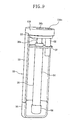
FIG. 9 , thecoolant intake 134a may extend down through thesection plate 32 by aninlet pipe 62 and thegas coolant inlet 36a may be formed above thesection plate 32. - Further, as shown in
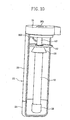
FIG. 10 , thecoolant intake 34a (shown inFIG. 5 ) may extend to the upper portion of thesection plate 32 by aninclined inlet pipe 162, in which theprotrusion 46 shown inFIG. 5 is not needed and the other configuration is the same as inFIGS. 3 and5 . -
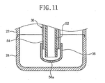
FIG. 11 is a cross-sectional view showing thelower part 24 of the tank in which thereturn cap 56 is disposed. As shown inFIG. 11 , anoil return hole 56a is formed through thereturn cap 56 to allow the oil for the compressor (oil separated from the coolant) to flow into and circulate through the coolant outlet pipe (dual pipe). Theinternal pipe 52 of thedual pipe 36 extends down more than theexternal pipe 54 to allow the oil to easily flow into theinternal pipe 52. - On the other hand, as shown in
FIG. 12 , afilter 64 is provided over thereturn cap 56 to prevent any foreign substances from flowing into theinternal pipe 52 through theoil return hole 56a. Afilter 66 may be provided at the lower end of theinternal pipe 52. - Further, as shown in
FIG. 13 , the oil that has flowed in thetank 20 is separated in to oil, a liquid coolant, and a gas coolant from the bottom of the tank and it is preferable to form the bottom of the tank under thereturn cap 56 deeper than other portions to easily collect and return the oil, in which the explosion means 38 shown inFIG. 3 is combined with the higher portion of the bottom of the tank. - The explosion means 38 is composed of an
explosion plate 38a fixed to the bottom of the tank, ahousing 38b of a vertical pipe and ahorizontal pipe 38c that are sequentially connected to theexplosion plate 38a. Theexplosion plate 38a is disposed between the machined surface of thelower part 24 of the tank and thehousing 38b of vertical pipe. - In the accumulator of an air conditioner having the above configuration according to the embodiment of the invention, as indicated by the arrows in
FIGS. 3 and4 , as the coolant that flows into theupper body 34 through thecoolant intake 34a of theupper body 34. rotates along the wall and hits theprotrusion 46, a liquid coolant is formed and flows down into thetank 20 and oil, a liquid coolant, and a gas coolant are separated. The gas coolant flows into thedual pipe 36, i.e. between theinternal pipe 52 and theexternal pipe 54 through thegas coolant inlet 36a, turns into theinternal pipe 52 at thereturn cap 56, and continues flowing up through thegas coolant outlet 36b to the outer pipe. - On the other hand, it is preferable for the accumulator to increase the diameter of the tank to increase capacity; however, it is strongly required to reduce the outer diameter of the tank because it is restricted by space in a small space, such as an engine room of a vehicle, and it is needed to improve liquid-vapor separating performance and pressure resistance in the tank of a accumulator of a small diameter to solve the above-mentioned problems. In general, the tank of an accumulator requires larger capacity than a liquid receiver, so that the diameter of the tank is usually set at 60 mm or more.
-
FIG. 14 shows a graph illustrating liquid-vapor separating performance to the diameter of the tank equipped with a dual pipe according to the embodiment of the invention andFIG. 15 shows a graph illustrating pressure resistance to the diameter of the tank equipped with a dual pipe according to the embodiment. - As shown in
FIG. 14 , a region of a liquid coolant under normal operating condition appears when the ratio of a liquid coolant in the tank of the accumulator to the entire inside volume is 0.65 in a common liquid-vapor separating tank. Considering the amount of liquid coolant in the liquid-vapor separating tank that is needed in an air conditioner is at a minimum 250 cc to a maximum 800 cc, it can be seen from the graph that the liquid-vapor separating performance is good when the diameters are in the range of 30 mm to 60 mm. - Further, as shown in
FIG. 15 , for the range of minimum 250 cc to maximum 800 cc that is a reasonable range of capacity of a liquid-vapor separating tank that is improved in liquid-vapor separating performance, it can be seen from the graph that, in the supercritical cooling cycle under high pressure, tanks of 30 mm to 60 mm diameter shows relatively better characteristics in pressure resistance than a tank of 60 mm diameter in the related art. - An accumulator of an air conditioner according to a second embodiment of the invention has an integral internal heat exchanger. The accumulator of an air conditioner according to the first embodiment of the invention does not include an internal heat exchanger, but the accumulator of an air conditioner according to this embodiment of the invention includes an additional mechanism that flows a coolant for internal heat exchange into the tank and circulates it therein.
- In the second embodiment of the invention, hereafter, in order to distinguish the coolant for internal heat exchange from the coolant that is separated into a liquid and a gas through the coolant outlet pipe, the coolant for internal heat exchange is referred to as a 'high-pressure coolant' and the coolant that is separated into a liquid and a gas through the coolant outlet pipe is referred to as a 'low-pressure coolant'.
- As shown in
FIG. 16 , in an accumulator of an air conditioner according to the second embodiment of the invention, a low-pressurecoolant inlet pipe 322 through which a low-pressure coolant flows is disposed at the upper portion inside ahollow tank 320 and a low-pressurecoolant outlet pipe 324 is vertically disposed at the center inside thetank 320 to discharge a gas coolant separated from the coolant that has flowed in the tank. - Further, the high-pressure
coolant inlet pipe 326 longitudinally covers a part of the outside of the low-pressurecoolant outlet pipe 324 for heat exchange with the low-pressure coolant, and a high-pressurecoolant outlet pipe 328 longitudinally covers the other part of the outside of the low-pressurecoolant outlet pipe 324 for heat exchange with the low-pressure coolant while being communicated with the lower end of the high-pressurecoolant inlet pipe 326. - The
tank 320 is composed of atank body 320a and alower part 320b of the tank combined to the lower portion of thetank body 320a, or thetank body 320a and thelower part 320b of the tank may be integrally formed by forging and anupper body 321 is combined to the upper end of thetank body 320a. Thetank 320 may be composed of thetank body 320a and thelower part 320b of the tank that are integrally formed. - The low-pressure
coolant inlet pipe 322 is disposed with the upper portion passing through theupper body 321 and the outside of the lower portion havingcoolant injection hole 322a to inject a coolant to the high-pressurecoolant inlet pipe 326, the high-pressurecoolant outlet pipe 328, or the inside of thetank 320 and improve liquid-vapor separating performance while the injected coolant rotates. - The low-
pressure outlet pipe 324 is a dual pipe with aninternal pipe 324a and anexternal pipe 324b and areturn cap 330 is combined to the lower end of the dual pipe. Accordingly, a gas coolant flows from the upper portion inside thetank 320 through a gas coolant inlet E1 between theinternal pipe 324a and theexternal pipe 324b and turns into theinternal pipe 324a at thereturn cap 330. - The upper and lower portions of the
internal pipe 324a extends more than the upper and lower ends of theexternal pipe 324b and the upper end of theinternal pipe 324a is positioned through theupper body 321. The gas coolant inlet E1 is formed under theupper body 321. - The low-pressure
coolant outlet pipe 324 is an extruded dual pipe with theinternal pipe 324a and theexternal pipe 324b that are integrally formed, or the internal pipe and the external pipe are formed by combining separate internal pipe with external pipe. - The high-pressure
coolant inlet pipe 326 has aninlet 326a that is positioned through theupper body 321 and aheat exchanging portion 326b through which heat is exchanged with a low-pressure coolant in thetank 320. The high-pressurecoolant outlet pipe 328 has anoutlet 328a that is positioned through theupper body 321 and aheat exchanging portion 328b through which heat is exchanged with the low-pressure coolant in thetank 320. - As shown in
FIG. 17 , theheat exchanging portions coolant inlet pipe 326 and the high-pressurecoolant outlet pipe 328 are each formed of a thin tube that is curved in the width,direction and has a plurality of coolant passages H inside. Theheat exchanging portions - The
inlet 326a of the high-pressurecoolant inlet pipe 326 and theoutlet 328a of the high-pressurecoolant outlet pipe 328 are each formed of one coolant passage, and theinlet 326a and theoutlet 328a are communicated with correspondingheat exchanging portions - The curved thin tube (
heat exchanging portions - The outsides of the high-
pressure coolant pipes coolant outlet pipe 324 are joined and arranged such that the coolants in the high-pressure coolant pipes coolant outlet pipe 324. - Heat
conductive fins 332 are provided on the outside of the curved thin tube (heat exchanging portions - The lower ends of the high-pressure
coolant inlet pipe 326 and the high-pressurecoolant outlet pipe 328 are communicated by aconnection cap 334. Theconnection cap 334 may be integrally formed with thereturn cap 330. - An
oil return hole 330a is formed through thereturn cap 330 to allow the oil for the compressor (oil separated from the coolant) to flow into and circulate through theinternal pipe 324a of the low-pressurecoolant outlet pipe 324. A filter (not shown) may be provided over thereturn cap 330 to prevent any foreign substances to flow inside through theoil return hole 330a. -
FIG. 18 shows another embodiment of the heat exchanging portion of the high-pressurecoolant inlet pipe 326 and the high-pressurecoolant outlet pipe 328 of the invention. Protruding heatconductive fins 432 are integrally formed, on the curved outside, withheat exchanging portions -
FIG. 19 shows another embodiment of the heat exchanging portion of the high-pressurecoolant inlet pipe 326 and the high-pressurecoolant outlet pipe 328 of the invention. Individual heatconductive fins 532 of offset fins with folds are attached to the curved outside of heat exchanging portions 526b, 528b of the invention. The heatconductive fins 532 of offset fins with folds increases the heat exchange rate by increasing the heat exchange area. - According to the accumulator equipped with an integral internal heat exchanger of an air conditioner having the above configuration of the invention, as shown by arrows in
FIG. 16 , a low-pressure coolant that flows from the evaporator 4 (shown inFIG. 1 ) into the upper portion inside thetank 320 through the low-pressurecoolant inlet pipe 322 is separated into oil, a liquid coolant, and a gas coolant while flowing down. - The liquid-vapor separating performance is increased by injecting the coolant through the
coolant injection hole 322a to the high-pressurecoolant inlet pipe 326, the high-pressurecoolant outlet pipe 328, or the inside of thetank 320. - The separated gas coolant flows inside through the gas coolant inlet E1 between the
internal pipe 324a andexternal pipe 324b of the low-pressurecoolant outlet pipe 324, turns up into theinternal pipe 324a at thereturn cap 330, and then continues flowing to the outer pipe toward the compressor 1 (shown inFIG. 1 ). The stagnant oil for the compressor at the lower portion in thetank 320 returns to the compressor through theoil return hole 330a. - Further, the high-pressure coolant that flows from the condenser 2 (gas cooler) (shown in
FIG. 1 ) into the high-pressurecoolant inlet pipe 326 exchanges heat with the gas coolant in the low-pressurecoolant outlet pipe 324 and the low-pressure coolant in thetank 320 while passing through theheat exchanging portion 326b, exchanges heat with the gas coolant in the low-pressure outlet pipe 324 and the low-pressure coolant in thetank 320 while passing through theheat exchanging portion 328b of the high-pressurecoolant outlet pipe 328 across theconnection cap 334, and then continues flowing through theoutlet 328a of the high-pressurecoolant outlet pipe 328 to the outer pipe toward the throttle valve 3 (shown inFIG. 1 ). - An accumulator of an air conditioner according to an embodiment of the invention can be formed of a small tank, so that it can be easily mounted in a small space and is improved in vapor-liquid separating performance with high pressure resistance.
- Further, according to an accumulator of an air conditioner according to another embodiment of the invention, an internal heat exchanger is integrally provided in the accumulator, such that system efficiency is increased by increase in heat exchange efficiency inside the body of the accumulator. Further, the internal heat exchanger is integrally provided without providing a specific internal heat exchanger outside, such that the coolant inlet and outlet are formed at the upper portion of the body of the accumulator and piping is easy.
Claims (24)
- An accumulator of an air conditioner, comprising:a tank (20);a coolant intake (34a) that is formed at the upper portion inside the tank (20); anda coolant outlet pipe (36) that is vertically disposed in the tank (20) to discharge a gas coolant separated from a coolant that has flowed in the tank (20), and has a gas coolant outlet (36b) at the upper portion of the tank (20),wherein the coolant outlet pipe (36) is a dual pipe (36) with an internal pipe (52) and an external pipe (54), anda return cap (56) is combined to the lower end of the dual pipe (36), the gas coolant flows from the upper portion inside the tank (20) through a gas coolant inlet (36a) between the internal pipe (52) and the external pipe (54), turns into the internal pipe (52) at the return cap (56), and then continues flowing through the gas coolant outlet (36b) to an outer pipe, characterized in thatan explosion plate (38a) that explodes under a predetermined pressure to rapidly discharge a coolant outside at an abnormal high pressure is provided at lower portion of the tank (20).
- The accumulator of an air conditioner as set forth in claim 1,
wherein the coolant intake is formed above a section plate (32) disposed at the upper portion inside the tank (20),
the gas coolant inlet (36a) is formed under the section plate (32), and
a liquid coolant block pipe (58) that surrounds the gas coolant inlet (36a) to prevent a liquid coolant from flowing into the coolant outlet pipe (36) through the gas coolant inlet (36a) is formed under the section plate (32). - The accumulator of an air conditioner as set forth in claim 2, wherein the liquid coolant block pipe (58) is a cone-shaped pipe with the top cut and the lower end open.
- The accumulator of an air conditioner as set forth in claim 2, wherein the liquid coolant block pipe (58) is a cylindrical pipe with the lower end open.
- The accumulator of an air conditioner as set forth in claim 2, wherein the passage area defined by a gap between the liquid coolant block pipe (58) and the external pipe (54) of the coolant outlet pipe (36) is larger than the passage area between the internal pipe (52) and external pipe (54) of the coolant outlet pipe (36).
- The accumulator of an air conditioner as set forth in claim 1, wherein the coolant inlet extends to the lower portion of the section plate (32) and the gas coolant inlet pipe is formed above the section plate (32).
- The accumulator of an air conditioner as set forth in claim 1, wherein an upper body (34) that has the coolant intake (34a) and a gas coolant outlet (36b) that is formed by connection with the internal pipe (52) of the dual pipe (36) is combined to the upper end of the tank (20).
- The accumulator of an air conditioner as set forth in claim 7, wherein a coolant inlet of the upper body (34) is formed at the side of the upper body (34) and communicated with the coolant intake (34a) to easily separate liquid and vapor from a coolant that flows into the upper portion inside the tank by circumferentially rotating the coolant.
- The accumulator of an air conditioner as set forth in claim 8, wherein a protrusion (46) with a round side is formed at the bottom of the upper body (34) where the internal pipe (52) of the dual pipe (36) is connected, in order to easily induce a cyclone by allowing the coolant that flows into the tank (20) through the coolant intake (34a) to hit the round side and easily rotate.
- The accumulator of an air conditioner as set forth in claim 1, wherein an oil return hole (14c) is formed in the return cap (56) to allow oil for a compressor (oil separated from the coolant) to flow into and circulate through the coolant outlet pipe (36).
- The accumulator of an air conditioner as set forth in claim 10, wherein a filter (64) is provided to the return cap (56) to prevent any foreign substances from flowing inside through the oil return hole.
- The accumulator of an air conditioner as set forth in claim 10, wherein the bottom of the tank (20) under the return cap (56) is formed deeper than other portions to easily collect and recover the oil.
- The accumulator of an air conditioner as set forth in claim 11, wherein the bottom of the tank (20) under the return cap (56) is formed deeper than other portions to easily collect and recover the oil.
- The accumulator of an air conditioner as set forth in claim 1, wherein the diameter of the tank (20) of the accumulator is in the range of 30 mm to 60 mm so that the accumulator is mounted in a small space with high liquid-vapor separating performance and pressure resistance.
- The accumulator of an air conditioner as set forth in claim 1, further comprising:a high-pressure coolant inlet pipe (326) that longitudinally surrounds a part of the outside of the external pipe (54) of the coolant outlet pipe (36); anda high-pressure coolant outlet pipe (328) that longitudinally surrounds the other part of the outside of the external pipe (54) of the coolant outlet pipe (36),wherein a connection cap (334) is combined to the lower ends of the high-pressure coolant inlet pipe (326) and the high-pressure coolant outlet pipe (328) such that the coolant that flows inside through the high-pressure coolant inlet pipe (326) turns into the high-pressure coolant outlet pipe (328) at the connection cap (334).
- The accumulator of an air conditioner as set forth in claim 15, wherein the high-pressure coolant inlet pipe (326) and the high-pressure coolant outlet pipe (328) each have a curved thin tube with a plurality of coolant passage inside.
- The accumulator of an air conditioner as set forth in claim 16, wherein the curved insides of the curved thin tubes is joined to the outside of the external pipe (54) of the coolant outlet pipe (36) so that the coolant in the coolant outlet pipe (36) exchanges heat with the coolants in the high-pressure coolant inlet pipe (326) and the high-pressure coolant outlet pipe (328).
- The accumulator of an air conditioner as set forth in claim 16, wherein heat conductive fins (332) are provided on the curved outside of the curved thin tube.
- The accumulator of an air conditioner as set forth in claim 18, wherein the heat conductive fins (332) are integrally formed with the curved thin tube, protruding outside.
- The accumulator of an air conditioner as set forth in claim 18, wherein the heat conductive fin (332) is an offset fin with folds.
- The accumulator of an air conditioner as set forth in claim 18, wherein the heat conductive fin (332) is a flat fin that is inserted around the curved thin tube.
- The accumulator of an air conditioner as set forth in claim 18, wherein the curved thin tube is formed by being pressed in a curved thin tube shape without post-machining.
- The accumulator of an air conditioner as set forth in claim 15, wherein the connection cap (334) is integrally formed with the return cap of the coolant outlet pipe (36).
- The accumulator of an air conditioner as set forth in claim 15, wherein the coolant intake (34a) is a pipe that is vertically disposed from the upper portion through the tank (20) and has a coolant injection hole (322a) through the outside of the pipe to rotate an injected coolant.
Applications Claiming Priority (1)
| Application Number | Priority Date | Filing Date | Title |
|---|---|---|---|
| KR1020060078186A KR100784611B1 (en) | 2006-08-18 | 2006-08-18 | Gas-liquid separator with internal heat exchanger of cooling system |
Publications (3)
| Publication Number | Publication Date |
|---|---|
| EP1890096A2 EP1890096A2 (en) | 2008-02-20 |
| EP1890096A3 EP1890096A3 (en) | 2013-05-01 |
| EP1890096B1 true EP1890096B1 (en) | 2015-03-11 |
Family
ID=38720344
Family Applications (1)
| Application Number | Title | Priority Date | Filing Date |
|---|---|---|---|
| EP07016164.1A Active EP1890096B1 (en) | 2006-08-18 | 2007-08-17 | Accumulator of air conditioner |
Country Status (3)
| Country | Link |
|---|---|
| US (2) | US20080041093A1 (en) |
| EP (1) | EP1890096B1 (en) |
| KR (1) | KR100784611B1 (en) |
Families Citing this family (14)
| Publication number | Priority date | Publication date | Assignee | Title |
|---|---|---|---|---|
| FR2928997B1 (en) * | 2008-03-20 | 2014-06-20 | Valeo Systemes Thermiques | HEAT EXCHANGER AND INTEGRATED AIR CONDITIONING ASSEMBLY COMPRISING SUCH AN EXCHANGER. |
| JP5644469B2 (en) * | 2010-12-21 | 2014-12-24 | カルソニックカンセイ株式会社 | accumulator |
| JP5804911B2 (en) * | 2011-11-24 | 2015-11-04 | 株式会社不二工機 | Gas-liquid separator |
| DE102014113793A1 (en) * | 2014-02-07 | 2015-08-13 | Halla Visteon Climate Control Corporation | Refrigerant accumulator, in particular for motor vehicle refrigerant circuits |
| JP6594685B2 (en) * | 2015-07-13 | 2019-10-23 | 株式会社不二工機 | accumulator |
| JP6537911B2 (en) * | 2015-07-17 | 2019-07-03 | 株式会社不二工機 | accumulator |
| US10845106B2 (en) * | 2017-12-12 | 2020-11-24 | Rheem Manufacturing Company | Accumulator and oil separator |
| KR102750535B1 (en) * | 2019-05-31 | 2025-01-06 | 현대자동차 주식회사 | Gas-liquid separation device for vehicle |
| CN113758337B (en) * | 2020-06-03 | 2024-11-22 | 浙江雪波蓝科技有限公司 | Energy storage device, cold storage system, cold storage and supply system and cold chain transport box |
| CN112097426B (en) * | 2020-09-07 | 2024-04-19 | 珠海格力电器股份有限公司 | Gas-liquid separator, air conditioning system and control method thereof |
| DE102021125240A1 (en) * | 2020-11-20 | 2022-05-25 | Hanon Systems | Device for separating a gaseous and a liquid phase of a working substance and for storing the liquid phase |
| DE102021201509B4 (en) * | 2021-02-17 | 2022-11-17 | Hanon Systems | Combination of a refrigerant accumulator and an internal refrigerant heat exchanger |
| EP4290159B1 (en) * | 2022-06-07 | 2025-11-19 | Carrier Corporation | Accumulator heat exchanger |
| CN119573333B (en) * | 2024-12-16 | 2025-12-26 | 中绿中科储能技术有限公司 | Internal structure of the cold box and liquid air energy storage power station |
Citations (2)
| Publication number | Priority date | Publication date | Assignee | Title |
|---|---|---|---|---|
| US6453697B1 (en) * | 2001-04-23 | 2002-09-24 | Designed Metal Products, Inc. | Seal for vessel and method of forming same |
| CN2677728Y (en) * | 2004-03-02 | 2005-02-09 | 王青 | Explosion-proof tank for filling environmental protection refrigerant |
Family Cites Families (19)
| Publication number | Priority date | Publication date | Assignee | Title |
|---|---|---|---|---|
| US1384477A (en) * | 1918-04-03 | 1921-07-12 | Fred E Matthews | Fluid-pressure apparatus |
| US3257824A (en) * | 1964-12-16 | 1966-06-28 | Itt | Integral lubricant return riser for refrigeration systems |
| US4194370A (en) * | 1976-08-13 | 1980-03-25 | Tecumseh Products Company | Accumulator for refrigeration system |
| US4147479A (en) * | 1976-08-13 | 1979-04-03 | Tecumseh Products Company | Refrigeration system and method with compressor mounted accumulator |
| US4199960A (en) | 1978-10-26 | 1980-04-29 | Parker-Hannifin Corporation | Accumulator for air conditioning systems |
| US4551990A (en) * | 1984-10-18 | 1985-11-12 | Honoshowsky John C | Oil return apparatus for a refrigeration system |
| US4651540A (en) * | 1986-03-21 | 1987-03-24 | Tecumseh Products Company | Suction accumulator including an entrance baffle |
| US4627247A (en) * | 1986-03-21 | 1986-12-09 | Tecumseh Products Company | Suction accumulator |
| US4827725A (en) | 1988-07-05 | 1989-05-09 | Tecumseh Products Company | Suction accumulator with dirt trap |
| US5479790A (en) * | 1993-07-06 | 1996-01-02 | Bottum, Jr.; Edward W. | Suction accumulator structure |
| JP4042220B2 (en) | 1997-09-24 | 2008-02-06 | 株式会社デンソー | Refrigeration cycle equipment |
| CA2297598C (en) * | 2000-01-28 | 2003-12-23 | Ki-Sun Jason Ryu | Accumulator for an air-conditioning system |
| KR100359822B1 (en) * | 2000-05-24 | 2002-11-07 | 엘지전자 주식회사 | An air-conditioner |
| JP4492017B2 (en) * | 2000-11-09 | 2010-06-30 | 株式会社デンソー | Accumulator module |
| US6523365B2 (en) | 2000-12-29 | 2003-02-25 | Visteon Global Technologies, Inc. | Accumulator with internal heat exchanger |
| US6463757B1 (en) * | 2001-05-24 | 2002-10-15 | Halla Climate Controls Canada, Inc. | Internal heat exchanger accumulator |
| JP2003065161A (en) * | 2001-08-24 | 2003-03-05 | Kawasaki Heavy Ind Ltd | Motorcycle and vaporizer mounted on the motorcycle |
| US6681597B1 (en) | 2002-11-04 | 2004-01-27 | Modine Manufacturing Company | Integrated suction line heat exchanger and accumulator |
| US7287399B2 (en) * | 2004-02-17 | 2007-10-30 | Obrist Engineering Gmbh | Collector for the liquid phase of the working medium of an air-conditioning system |
-
2006
- 2006-08-18 KR KR1020060078186A patent/KR100784611B1/en active Active
-
2007
- 2007-08-14 US US11/889,523 patent/US20080041093A1/en not_active Abandoned
- 2007-08-17 EP EP07016164.1A patent/EP1890096B1/en active Active
-
2011
- 2011-02-25 US US13/035,764 patent/US20110146332A1/en not_active Abandoned
Patent Citations (2)
| Publication number | Priority date | Publication date | Assignee | Title |
|---|---|---|---|---|
| US6453697B1 (en) * | 2001-04-23 | 2002-09-24 | Designed Metal Products, Inc. | Seal for vessel and method of forming same |
| CN2677728Y (en) * | 2004-03-02 | 2005-02-09 | 王青 | Explosion-proof tank for filling environmental protection refrigerant |
Also Published As
| Publication number | Publication date |
|---|---|
| US20110146332A1 (en) | 2011-06-23 |
| KR100784611B1 (en) | 2007-12-11 |
| EP1890096A3 (en) | 2013-05-01 |
| US20080041093A1 (en) | 2008-02-21 |
| EP1890096A2 (en) | 2008-02-20 |
Similar Documents
| Publication | Publication Date | Title |
|---|---|---|
| EP1890096A2 (en) | Accumulator of air conditioner | |
| US9587888B2 (en) | Internal heat exchanger assembly | |
| US6523365B2 (en) | Accumulator with internal heat exchanger | |
| US7654108B2 (en) | Unit for refrigerant cycle device | |
| US12152817B2 (en) | Gas-liquid separation device and thermal management system | |
| US20070169512A1 (en) | Heat exchanger and refrigerant cycle device using the same | |
| US10935288B2 (en) | Condenser | |
| CN112432402B (en) | Gas-liquid separator and thermal management system | |
| JP3617083B2 (en) | Receiver integrated refrigerant condenser | |
| US20030051503A1 (en) | Refrigerant cycle system having discharge function of gas refrigerant in receiver | |
| US6341647B1 (en) | Separator-integrated condenser for vehicle air conditioner | |
| JP2827404B2 (en) | Refrigerant condenser | |
| CN212378295U (en) | Gas-liquid separator | |
| JP2001174103A (en) | Refrigerant condenser | |
| JPH08219588A (en) | Liquid receiver integration type refrigerant condenser | |
| JP6170422B2 (en) | Subcooled condenser with receiver tank with refrigerant path changer to improve charging efficiency | |
| US20060070724A1 (en) | Integrated receiver dryer sleeve | |
| KR20170047050A (en) | A condenser | |
| GB2386939A (en) | Accumulator with an internal heat exchanger | |
| CN113899115B (en) | Water-refrigerant heat exchange device and miniature refrigerating system | |
| JP2001099525A (en) | Liquid receiver and refrigeration cycle device | |
| EP3730872B1 (en) | Liquid collector and heat exchange device having liquid collector | |
| JP2006207995A (en) | Heat exchanger |
Legal Events
| Date | Code | Title | Description |
|---|---|---|---|
| PUAI | Public reference made under article 153(3) epc to a published international application that has entered the european phase |
Free format text: ORIGINAL CODE: 0009012 |
|
| 17P | Request for examination filed |
Effective date: 20070817 |
|
| AK | Designated contracting states |
Kind code of ref document: A2 Designated state(s): AT BE BG CH CY CZ DE DK EE ES FI FR GB GR HU IE IS IT LI LT LU LV MC MT NL PL PT RO SE SI SK TR |
|
| AX | Request for extension of the european patent |
Extension state: AL BA HR MK YU |
|
| PUAL | Search report despatched |
Free format text: ORIGINAL CODE: 0009013 |
|
| AK | Designated contracting states |
Kind code of ref document: A3 Designated state(s): AT BE BG CH CY CZ DE DK EE ES FI FR GB GR HU IE IS IT LI LT LU LV MC MT NL PL PT RO SE SI SK TR |
|
| AX | Request for extension of the european patent |
Extension state: AL BA HR MK RS |
|
| RIC1 | Information provided on ipc code assigned before grant |
Ipc: F25B 43/00 20060101AFI20130326BHEP |
|
| AKX | Designation fees paid |
Designated state(s): DE FR GB IT |
|
| GRAP | Despatch of communication of intention to grant a patent |
Free format text: ORIGINAL CODE: EPIDOSNIGR1 |
|
| INTG | Intention to grant announced |
Effective date: 20140919 |
|
| GRAS | Grant fee paid |
Free format text: ORIGINAL CODE: EPIDOSNIGR3 |
|
| GRAA | (expected) grant |
Free format text: ORIGINAL CODE: 0009210 |
|
| AK | Designated contracting states |
Kind code of ref document: B1 Designated state(s): DE FR GB IT |
|
| REG | Reference to a national code |
Ref country code: GB Ref legal event code: FG4D |
|
| REG | Reference to a national code |
Ref country code: DE Ref legal event code: R096 Ref document number: 602007040554 Country of ref document: DE Effective date: 20150423 |
|
| REG | Reference to a national code |
Ref country code: DE Ref legal event code: R097 Ref document number: 602007040554 Country of ref document: DE |
|
| PG25 | Lapsed in a contracting state [announced via postgrant information from national office to epo] |
Ref country code: IT Free format text: LAPSE BECAUSE OF FAILURE TO SUBMIT A TRANSLATION OF THE DESCRIPTION OR TO PAY THE FEE WITHIN THE PRESCRIBED TIME-LIMIT Effective date: 20150311 |
|
| PLBE | No opposition filed within time limit |
Free format text: ORIGINAL CODE: 0009261 |
|
| STAA | Information on the status of an ep patent application or granted ep patent |
Free format text: STATUS: NO OPPOSITION FILED WITHIN TIME LIMIT |
|
| 26N | No opposition filed |
Effective date: 20151214 |
|
| REG | Reference to a national code |
Ref country code: FR Ref legal event code: PLFP Year of fee payment: 10 |
|
| REG | Reference to a national code |
Ref country code: FR Ref legal event code: PLFP Year of fee payment: 11 |
|
| REG | Reference to a national code |
Ref country code: FR Ref legal event code: PLFP Year of fee payment: 12 |
|
| PGFP | Annual fee paid to national office [announced via postgrant information from national office to epo] |
Ref country code: GB Payment date: 20250624 Year of fee payment: 19 |
|
| PGFP | Annual fee paid to national office [announced via postgrant information from national office to epo] |
Ref country code: FR Payment date: 20250624 Year of fee payment: 19 |
|
| PGFP | Annual fee paid to national office [announced via postgrant information from national office to epo] |
Ref country code: DE Payment date: 20250624 Year of fee payment: 19 |