EP1890013A2 - Fluid calming member and method of forming the same - Google Patents
Fluid calming member and method of forming the same Download PDFInfo
- Publication number
- EP1890013A2 EP1890013A2 EP07252762A EP07252762A EP1890013A2 EP 1890013 A2 EP1890013 A2 EP 1890013A2 EP 07252762 A EP07252762 A EP 07252762A EP 07252762 A EP07252762 A EP 07252762A EP 1890013 A2 EP1890013 A2 EP 1890013A2
- Authority
- EP
- European Patent Office
- Prior art keywords
- fluid
- calming member
- carrying arrangement
- wall
- calming
- Prior art date
- Legal status (The legal status is an assumption and is not a legal conclusion. Google has not performed a legal analysis and makes no representation as to the accuracy of the status listed.)
- Granted
Links
Images
Classifications
-
- F—MECHANICAL ENGINEERING; LIGHTING; HEATING; WEAPONS; BLASTING
- F01—MACHINES OR ENGINES IN GENERAL; ENGINE PLANTS IN GENERAL; STEAM ENGINES
- F01D—NON-POSITIVE DISPLACEMENT MACHINES OR ENGINES, e.g. STEAM TURBINES
- F01D25/00—Component parts, details, or accessories, not provided for in, or of interest apart from, other groups
- F01D25/16—Arrangement of bearings; Supporting or mounting bearings in casings
- F01D25/162—Bearing supports
- F01D25/164—Flexible supports; Vibration damping means associated with the bearing
-
- B—PERFORMING OPERATIONS; TRANSPORTING
- B22—CASTING; POWDER METALLURGY
- B22F—WORKING METALLIC POWDER; MANUFACTURE OF ARTICLES FROM METALLIC POWDER; MAKING METALLIC POWDER; APPARATUS OR DEVICES SPECIALLY ADAPTED FOR METALLIC POWDER
- B22F10/00—Additive manufacturing of workpieces or articles from metallic powder
- B22F10/20—Direct sintering or melting
- B22F10/28—Powder bed fusion, e.g. selective laser melting [SLM] or electron beam melting [EBM]
-
- B—PERFORMING OPERATIONS; TRANSPORTING
- B22—CASTING; POWDER METALLURGY
- B22F—WORKING METALLIC POWDER; MANUFACTURE OF ARTICLES FROM METALLIC POWDER; MAKING METALLIC POWDER; APPARATUS OR DEVICES SPECIALLY ADAPTED FOR METALLIC POWDER
- B22F5/00—Manufacture of workpieces or articles from metallic powder characterised by the special shape of the product
-
- F—MECHANICAL ENGINEERING; LIGHTING; HEATING; WEAPONS; BLASTING
- F01—MACHINES OR ENGINES IN GENERAL; ENGINE PLANTS IN GENERAL; STEAM ENGINES
- F01D—NON-POSITIVE DISPLACEMENT MACHINES OR ENGINES, e.g. STEAM TURBINES
- F01D25/00—Component parts, details, or accessories, not provided for in, or of interest apart from, other groups
- F01D25/08—Cooling; Heating; Heat-insulation
- F01D25/12—Cooling
- F01D25/125—Cooling of bearings
-
- B—PERFORMING OPERATIONS; TRANSPORTING
- B22—CASTING; POWDER METALLURGY
- B22F—WORKING METALLIC POWDER; MANUFACTURE OF ARTICLES FROM METALLIC POWDER; MAKING METALLIC POWDER; APPARATUS OR DEVICES SPECIALLY ADAPTED FOR METALLIC POWDER
- B22F7/00—Manufacture of composite layers, workpieces, or articles, comprising metallic powder, by sintering the powder, with or without compacting wherein at least one part is obtained by sintering or compression
- B22F7/002—Manufacture of composite layers, workpieces, or articles, comprising metallic powder, by sintering the powder, with or without compacting wherein at least one part is obtained by sintering or compression of porous nature
- B22F7/004—Manufacture of composite layers, workpieces, or articles, comprising metallic powder, by sintering the powder, with or without compacting wherein at least one part is obtained by sintering or compression of porous nature comprising at least one non-porous part
-
- B—PERFORMING OPERATIONS; TRANSPORTING
- B33—ADDITIVE MANUFACTURING TECHNOLOGY
- B33Y—ADDITIVE MANUFACTURING, i.e. MANUFACTURING OF THREE-DIMENSIONAL [3D] OBJECTS BY ADDITIVE DEPOSITION, ADDITIVE AGGLOMERATION OR ADDITIVE LAYERING, e.g. BY 3D PRINTING, STEREOLITHOGRAPHY OR SELECTIVE LASER SINTERING
- B33Y80/00—Products made by additive manufacturing
-
- F—MECHANICAL ENGINEERING; LIGHTING; HEATING; WEAPONS; BLASTING
- F05—INDEXING SCHEMES RELATING TO ENGINES OR PUMPS IN VARIOUS SUBCLASSES OF CLASSES F01-F04
- F05D—INDEXING SCHEME FOR ASPECTS RELATING TO NON-POSITIVE-DISPLACEMENT MACHINES OR ENGINES, GAS-TURBINES OR JET-PROPULSION PLANTS
- F05D2230/00—Manufacture
- F05D2230/20—Manufacture essentially without removing material
- F05D2230/22—Manufacture essentially without removing material by sintering
-
- Y—GENERAL TAGGING OF NEW TECHNOLOGICAL DEVELOPMENTS; GENERAL TAGGING OF CROSS-SECTIONAL TECHNOLOGIES SPANNING OVER SEVERAL SECTIONS OF THE IPC; TECHNICAL SUBJECTS COVERED BY FORMER USPC CROSS-REFERENCE ART COLLECTIONS [XRACs] AND DIGESTS
- Y02—TECHNOLOGIES OR APPLICATIONS FOR MITIGATION OR ADAPTATION AGAINST CLIMATE CHANGE
- Y02P—CLIMATE CHANGE MITIGATION TECHNOLOGIES IN THE PRODUCTION OR PROCESSING OF GOODS
- Y02P10/00—Technologies related to metal processing
- Y02P10/25—Process efficiency
Definitions
- This invention relates to fluid calming members. More particularly, but not exclusively, the invention relates to fluid calming members in fluid chambers in gas turbine engines. This invention may also relate to fluid chambers. This invention may relate to processes for forming fluid calming members.
- Embodiments of the invention relate to fluid calming formations such as baffles and shrouds which are used in gas turbine engines to control fluid recirculation, thereby reducing heat generation.
- fluid calming formations such as baffles and shrouds which are used in gas turbine engines to control fluid recirculation, thereby reducing heat generation.
- a disadvantage of known formations is that they can create splashing of the fluid thereby reducing their efficiency in reducing heat generation.
- a fluid calming member for use in a fluid carrying arrangement, wherein the fluid calming member comprises a porous metallic material.
- a fluid carrying arrangement comprising a wall defining a space for a fluid, and a fluid calming member in the space, wherein the fluid calming member comprises a porous metallic material.
- fluid carrying arrangement refers to any arrangement capable of containing a fluid, or allowing a fluid to flow therethrough.
- the fluid carrying arrangement may comprise a fluid chamber.
- the fluid calming member may be formed of a sintered metallic material, and may be formed by a solid free form fabrication process, which may comprise selective melting or sintering, such as selective laser or electron melting or sintering.
- the fluid calming member may comprise an inner wall member mounted on the fluid carrying arrangement wall.
- the fluid calming member may comprise a baffle.
- the fluid calming member may comprise a shroud.
- the fluid carrying arrangement may have a plurality of fluid calming members.
- the fluid calming member may be formed of a metal foam material.
- the fluid calming member may comprise substantially non-porous regions to allow the fluid calming member to be secured within the space.
- Lug portions may be provided on the wall of the fluid carrying arrangement at which the fluid calming member can be secured.
- the lug portions may be arranged on the wall to be in register with the substantially non-porous regions when the inner wall member is secured to the chamber wall.
- a method of forming a fluid calming member comprising providing a powder of a metallic material and processing the powder into a porous material to form the fluid calming member.
- the step of processing the powder may comprise solid freeform fabrication.
- the step of processing the powder may comprise sintering the material to provide the fluid calming member formed of the porous material.
- the step of processing the powder may comprise selective laser or electron beam melting or sintering.
- the method may include forming substantially non-porous regions in the fluid calming member, at which the fluid calming member can be secured to a chamber wall of a fluid chamber.
- a fluid carrying arrangement comprising a first part and a second part in the first part wherein at least one of the first and second parts is adapted to carry a fluid, and at least one of the first and second parts is formed by a solid free form fabrication process.
- a method of forming fluid carrying arrangement comprising providing a first part and a second part in the first part, wherein at least one of the first and second part can to carry a fluid, and the method comprises forming at least one of the first and second parts by a solid free form fabrication process.
- the solid free form fabrication process may comprise a selective melting or sintering process, such as selective laser or electron melting or sintering.
- At least one of the first and second parts may comprise a porous metallic material.
- the part comprising the porous metallic material may be formed by the solid free form fabrication process.
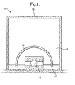
- Fig 1 is a diagrammatic view of a fluid chamber 10.
- the fluid chamber 10 is a bearing housing in which a bearing 12 is housed.
- the fluid chamber 10 could be any other suitable chamber for containing a fluid 14, or for allowing a fluid 14 to flow therethrough, such as a conduit or a chamber for a gear coupling, bolt sequence or any fluid source of windage element.
- the fluid flowing through or contained in the chamber 10 could be oil or any other suitable fluid.
- the chamber 10 comprises a chamber wall 16 defining a space 17.
- a fluid calming member in the form of a shroud 18 surrounding the bearing 12 The shroud 18 is formed of a porous metallic material, such as titanium, and can be a metal foam material or a sintered material formed by a solid free form fabrication process, such as selective laser melting or sintering (see below).
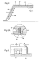
- a fluid calming member in the form of a wall member 118 is secured to the chamber wall 16 by lugs 20.
- the inner wall member 118 defines with the chamber wall 16 a drain zone 22 in which the rate of flow of fluid 14 is greatly reduced, thereby reducing heat absorption by the fluid 14.
- the porous nature of the fluid calming member 18 allows fluid to percolate therethrough to the drain zone 22 and to flow through the drain zone at a reduced velocity, and minimise re-entrainment into the main chamber.
- the region marked A in Fig 2 is shown in close up in Fig 2A and it can be seen that the inner wall member 118 is formed of a porous metallic material such as titanium and may be formed by selective laser melting or sintering, as mentioned above.
- the inner wall member 118 also has a plurality of substantially non-porous regions 24 which define countersunk apertures 26 for receiving a countersunk bolt 28.
- the non-porous regions 24 are arranged within the fluid calming member 18 such that when the fluid calming member 118 is mounted on the chamber wall 16, the non-porous region 24 are in register with the lugs 20.
- the lugs 20 define a threaded recess 30 in to which the countersunk bolt 28 can be threadably received thereby securing the fluid calming member 18 to the chamber wall 16.
- the countersunk bolt could be a conventional bolt or rivet or the fastening means.
- a fluid calming member in the form of a baffle 218 is provided.
- the baffle 218, being formed of a porous metallic material is provided to reduce the velocity of fluid 14 striking the baffle 218.
- the porous nature of the baffle 218 inhibits splashing of the fluid 14 on striking the baffle 218. This has the advantage in this embodiment of improving the efficiency as compared to prior art fluid chambers.
- the fluid 14 flowing through the space 17 remains in a calm state.
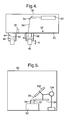
- FIG 4 there is shown a first embodiment of a method of forming a fluid calming member.
- the method comprises providing a manufacturing compartment 30 within which a laser or electron beam device 32 is provided.
- a mirror 34 acts to control a beam 36 of laser light or electrons.
- a work piece 38 is provided beneath the manufacturing compartment 30 such that the upper portion 40 thereof extends in to the manufacturing compartment 30.
- a film 42 of a titanium powder 43 is provided within the manufacturing compartment 30 and covers the work piece 38.
- a supply 44 of the powder 43 is provided in which a piston 46 can deliver the powder 43 into the manufacturing compartment 30.
- the film 42 of the powder 43 is levelled by a levelling device 46.
- the vertical position of the work piece 38 is controlled by a height control device 48 which can move up and down as shown by the arrows A.
- the laser or electron beam device 32 transmits a beam of electrons or laser light at the film 42 of the metallic powder covering the work piece 38 to sinter the metallic power 42 in a layer on the work piece 38.
- the height control device 48 moves the work piece downwardly and further powder 42 is then provided over the work piece 38, and the electron beam device is actuated to produce a further layer of the material on the work piece 38. This process is repeated until the fluid calming member has been fully formed from the work piece.
- the laser/electron beam device 32 is controlled by an appropriate computer controlled system as would be understood by those skilled in the art.
- the embodiment shown in Fig 5 comprises a support platform 50 on which the work piece 38 is provided.
- a further laser or electron beam device 132 is provided and supported by a positioning and scanning device 134.
- a powder dispenser 136 is also supported by the positioning and scanning device 134. The powder dispenser 136 dispenses a layer of the powder 43 onto the work piece 38 for formation into a layer of the work piece 38.
- the positioning and scanning device 134 positions the laser or electron beam device132 to transmit a beam of laser light or electrons at the work piece after the powder dispenser has dispensed a layer of powder on to the work piece.
- a further layer of powder 43 is dispensed by the powder dispenser 136 onto the work piece 38. This is repeated until the work piece 38 is fully formed.
- the fluid calming member When the fluid calming member has been fully formed, it is then arranged within the chamber 10 to provide a wall member, baffle or shroud as described above.
- titanium powder is referred to, it will be appreciated that any suitable material could be employed instead.
Landscapes
- Engineering & Computer Science (AREA)
- Mechanical Engineering (AREA)
- General Engineering & Computer Science (AREA)
- Manufacturing & Machinery (AREA)
- Physics & Mathematics (AREA)
- Plasma & Fusion (AREA)
- Chemical & Material Sciences (AREA)
- Materials Engineering (AREA)
- Powder Metallurgy (AREA)
- Air Bags (AREA)
Abstract
Description
- This invention relates to fluid calming members. More particularly, but not exclusively, the invention relates to fluid calming members in fluid chambers in gas turbine engines. This invention may also relate to fluid chambers. This invention may relate to processes for forming fluid calming members.
- Embodiments of the invention relate to fluid calming formations such as baffles and shrouds which are used in gas turbine engines to control fluid recirculation, thereby reducing heat generation. A disadvantage of known formations is that they can create splashing of the fluid thereby reducing their efficiency in reducing heat generation.
- According to one aspect of this invention, there is provided a fluid calming member for use in a fluid carrying arrangement, wherein the fluid calming member comprises a porous metallic material.
- According to another aspect of this invention, there is provided a fluid carrying arrangement comprising a wall defining a space for a fluid, and a fluid calming member in the space, wherein the fluid calming member comprises a porous metallic material.
- The phrase "fluid carrying arrangement" as used herein refers to any arrangement capable of containing a fluid, or allowing a fluid to flow therethrough.
- The fluid carrying arrangement may comprise a fluid chamber. The fluid calming member may be formed of a sintered metallic material, and may be formed by a solid free form fabrication process, which may comprise selective melting or sintering, such as selective laser or electron melting or sintering.
- The fluid calming member may comprise an inner wall member mounted on the fluid carrying arrangement wall. Alternatively, the fluid calming member may comprise a baffle. Alternatively, the fluid calming member may comprise a shroud. The fluid carrying arrangement may have a plurality of fluid calming members.
- The fluid calming member may be formed of a metal foam material. The fluid calming member may comprise substantially non-porous regions to allow the fluid calming member to be secured within the space. Lug portions may be provided on the wall of the fluid carrying arrangement at which the fluid calming member can be secured. The lug portions may be arranged on the wall to be in register with the substantially non-porous regions when the inner wall member is secured to the chamber wall.
- According to a further aspect of this invention there is provided a method of forming a fluid calming member, comprising providing a powder of a metallic material and processing the powder into a porous material to form the fluid calming member.
- The step of processing the powder may comprise solid freeform fabrication. The step of processing the powder may comprise sintering the material to provide the fluid calming member formed of the porous material. The step of processing the powder may comprise selective laser or electron beam melting or sintering.
- The method may include forming substantially non-porous regions in the fluid calming member, at which the fluid calming member can be secured to a chamber wall of a fluid chamber.
- According to another aspect of this invention there is provided a fluid carrying arrangement comprising a first part and a second part in the first part wherein at least one of the first and second parts is adapted to carry a fluid, and at least one of the first and second parts is formed by a solid free form fabrication process.
- According to another aspect of this invention, there is provided a method of forming fluid carrying arrangement, comprising providing a first part and a second part in the first part, wherein at least one of the first and second part can to carry a fluid, and the method comprises forming at least one of the first and second parts by a solid free form fabrication process.
- The solid free form fabrication process may comprise a selective melting or sintering process, such as selective laser or electron melting or sintering.
- At least one of the first and second parts may comprise a porous metallic material. The part comprising the porous metallic material may be formed by the solid free form fabrication process.
- Embodiments of the invention will now be described by way of example only, with reference to the accompanying drawings, in which:
- Fig 1 is a diagrammatic view of a fluid chamber;
- Fig 2 is a diagrammatic view of a region of the chamber wall;
- Fig 2A is a close up of the region marked A in Fig 2;
- Fig 3 is a diagrammatic view of a baffle within the chamber;
- Fig 4 is a diagrammatic view showing a first method of forming a fluid calming device; and
- Fig 5 is a diagrammatic view of a second method for forming a fluid calming device.
- Referring to the drawings, Fig 1 is a diagrammatic view of a
fluid chamber 10. In the embodiment shown in Fig 1, thefluid chamber 10 is a bearing housing in which abearing 12 is housed. However, it will be appreciated that thefluid chamber 10 could be any other suitable chamber for containing afluid 14, or for allowing afluid 14 to flow therethrough, such as a conduit or a chamber for a gear coupling, bolt sequence or any fluid source of windage element. The fluid flowing through or contained in thechamber 10 could be oil or any other suitable fluid. - In the embodiment shown in Fig. 1, the
chamber 10 comprises achamber wall 16 defining aspace 17. A fluid calming member in the form of ashroud 18 surrounding thebearing 12 Theshroud 18 is formed of a porous metallic material, such as titanium, and can be a metal foam material or a sintered material formed by a solid free form fabrication process, such as selective laser melting or sintering (see below). - Referring to Fig 2, there is shown a further embodiment, similar to that shown in Fig 1, in which a fluid calming member in the form of a
wall member 118 is secured to thechamber wall 16 bylugs 20. Theinner wall member 118 defines with the chamber wall 16 a drain zone 22 in which the rate of flow offluid 14 is greatly reduced, thereby reducing heat absorption by thefluid 14. The porous nature of the fluidcalming member 18 allows fluid to percolate therethrough to the drain zone 22 and to flow through the drain zone at a reduced velocity, and minimise re-entrainment into the main chamber. - The region marked A in Fig 2 is shown in close up in Fig 2A and it can be seen that the
inner wall member 118 is formed of a porous metallic material such as titanium and may be formed by selective laser melting or sintering, as mentioned above. - The
inner wall member 118 also has a plurality of substantiallynon-porous regions 24 which definecountersunk apertures 26 for receiving acountersunk bolt 28. Thenon-porous regions 24 are arranged within the fluidcalming member 18 such that when the fluidcalming member 118 is mounted on thechamber wall 16, thenon-porous region 24 are in register with thelugs 20. As can be seen from Fig 2A, thelugs 20 define a threadedrecess 30 in to which thecountersunk bolt 28 can be threadably received thereby securing the fluidcalming member 18 to thechamber wall 16. The countersunk bolt could be a conventional bolt or rivet or the fastening means. - Referring to Fig 3, there is shown a region of the
space 17 defined by thechamber wall 16 in which a fluid calming member in the form of abaffle 218 is provided. Thebaffle 218, being formed of a porous metallic material is provided to reduce the velocity offluid 14 striking thebaffle 218. The porous nature of thebaffle 218 inhibits splashing of thefluid 14 on striking thebaffle 218. This has the advantage in this embodiment of improving the efficiency as compared to prior art fluid chambers. Thus thefluid 14 flowing through thespace 17 remains in a calm state. - Referring to Fig 4, there is shown a first embodiment of a method of forming a fluid calming member.
- The method comprises providing a
manufacturing compartment 30 within which a laser orelectron beam device 32 is provided. Amirror 34 acts to control abeam 36 of laser light or electrons. Awork piece 38 is provided beneath themanufacturing compartment 30 such that theupper portion 40 thereof extends in to themanufacturing compartment 30. Afilm 42 of atitanium powder 43 is provided within themanufacturing compartment 30 and covers thework piece 38. Asupply 44 of thepowder 43 is provided in which apiston 46 can deliver thepowder 43 into themanufacturing compartment 30. Thefilm 42 of thepowder 43 is levelled by alevelling device 46. In operation, the vertical position of thework piece 38 is controlled by aheight control device 48 which can move up and down as shown by the arrows A. - The laser or
electron beam device 32 transmits a beam of electrons or laser light at thefilm 42 of the metallic powder covering thework piece 38 to sinter themetallic power 42 in a layer on thework piece 38. After a layer has been formed, theheight control device 48 moves the work piece downwardly andfurther powder 42 is then provided over thework piece 38, and the electron beam device is actuated to produce a further layer of the material on thework piece 38. This process is repeated until the fluid calming member has been fully formed from the work piece. - The laser/
electron beam device 32 is controlled by an appropriate computer controlled system as would be understood by those skilled in the art. - In the embodiment shown in Fig 5, many of the features shown in Fig 4 are present, and these have been designated with the same reference numerals as in Fig 4. The embodiment shown in Fig 5 comprises a
support platform 50 on which thework piece 38 is provided. A further laser orelectron beam device 132 is provided and supported by a positioning andscanning device 134. Apowder dispenser 136 is also supported by the positioning andscanning device 134. Thepowder dispenser 136 dispenses a layer of thepowder 43 onto thework piece 38 for formation into a layer of thework piece 38. - The positioning and
scanning device 134 positions the laser or electron beam device132 to transmit a beam of laser light or electrons at the work piece after the powder dispenser has dispensed a layer of powder on to the work piece. - After each time that the laser or electron beam device has transmitted the beam of laser light or electron to sinter the
metallic powder 43 to form a further layer of thework piece 38, a further layer ofpowder 43 is dispensed by thepowder dispenser 136 onto thework piece 38. This is repeated until thework piece 38 is fully formed. - When the fluid calming member has been fully formed, it is then arranged within the
chamber 10 to provide a wall member, baffle or shroud as described above. - Various modifications can be made without departing from the scope of the invention.
- For example, although in the embodiments described titanium powder is referred to, it will be appreciated that any suitable material could be employed instead.
Claims (27)
- A fluid calming member (18, 118) for use in a fluid carrying arrangement, wherein the fluid calming member comprises a porous metallic material.
- A fluid calming member according to claim 1 wherein the fluid calming member is formed of a sintered metallic material, formed by a solid free form fabrication process.
- A fluid calming member according to claim 2 in the solid free form fabrication process comprises selective melting or sintering.
- A fluid calming member according to claim 2 or 3 wherein the solid free form fabrication process comprises selective laser or electron melting or sintering.
- A fluid calming member according to any preceding claim wherein the fluid calming member comprises an inner wall member (118) mounted on the fluid carrying arrangement wall (16).
- A fluid calming member according to any of claims 1 to 4 wherein the fluid calming member comprises a baffle.
- A fluid calming member according to any of claims 1 to 4 wherein the fluid calming member comprises a shroud.
- A fluid calming member according to any preceding claim wherein the fluid calming member (118) is formed of a metal foam material, and comprises substantially non-porous regions (24) to allow the fluid calming member (118) to be secured within the fluid carrying arrangement.
- A fluid calming member according to claim 8 wherein lug portions (20) are provided on the wall of the fluid carrying arrangement (118) at which the fluid calming member can be secured, the lug portions (20) being arranged on the wall (16) to be in register with the substantially non-porous regions (24) when the inner wall member (118) is secured to the chamber wall (16).
- A fluid carrying arrangement comprising a wall (16) defining a space for a fluid, and a fluid calming member (118) as claimed in any preceding claim in the space, wherein the fluid calming member (118) comprises a porous metallic material.
- A fluid carrying arrangement according to claim 10 wherein the fluid carrying arrangement comprises a fluid chamber.
- A fluid carrying arrangement according to claim 10 or 11 wherein the fluid carrying arrangement has a plurality of fluid calming members.
- A fluid carrying arrangement according to claim 10, 11 or 12 when dependent on claim 8 or 9 wherein lug portions (20) are provided on the chamber wall (16) at which the fluid calming member (118) can be secured.
- A fluid carrying arrangement according to claim 13 wherein the lug portions (20) are arranged on the wall (16) to be in register with the substantially non-porous regions (24) when the inner wall member is secured to the chamber wall.
- A method of forming a fluid calming member, comprising providing a powder of a metallic material and processing the powder into a porous material to form the fluid calming member.
- A method according to claim 15 wherein the step of processing the powder may comprise solid freeform fabrication.
- A method according to claim 15 or 16 wherein the step of processing the powder comprises selective sintering of the material to provide the fluid calming member formed of the porous material.
- A method according to claim 15, 16 or 17 wherein the step of processing the powder comprises selective laser or electron beam melting or sintering.
- A method according to any of claims 15 to 18 wherein the method includes forming substantially non-porous regions in the fluid calming member, at which the fluid calming member can be secured to a chamber wall of a fluid chamber.
- A fluid carrying arrangement comprising a first part and a second part in the first part wherein at least one of the first and second parts is adapted to carry a fluid, and at least one of the first and second parts is formed by a solid free form fabrication process.
- A fluid carrying arrangement according to claim 20 wherein the solid free form fabrication process comprises a selective melting or sintering process.
- A fluid carrying arrangement according to claim 20 or 21 wherein the free form fabrication process comprise selective laser or electron bean melting or sintering.
- A fluid carrying arrangement according to claim 20, 21 or 22 wherein at least one of the first and second parts comprises a porous metallic material, the part comprising the porous metallic material being formed by the solid free form fabrication process.
- A method of forming fluid carrying arrangement, comprising providing a first part and a second part in the first part, wherein at least one of the first and second parts can carry a fluid, and the method comprises forming at least one of the first and second parts by a solid free form fabrication process.
- A method according to claim 24 wherein the solid free form fabrication process comprises a selective melting or sintering process.
- A method according to claim 24 or 25 wherein the solid free form fabrication process comprises selective laser or electron bean melting or sintering.
- A method according to claim 24, 25 or 26 wherein at least one of the first and second parts comprises a porous metallic material, the part comprising the porous metallic material being formed by the solid free form fabrication process.
Applications Claiming Priority (1)
| Application Number | Priority Date | Filing Date | Title |
|---|---|---|---|
| GBGB0615383.7A GB0615383D0 (en) | 2006-08-03 | 2006-08-03 | Fluid calming member |
Publications (3)
| Publication Number | Publication Date |
|---|---|
| EP1890013A2 true EP1890013A2 (en) | 2008-02-20 |
| EP1890013A3 EP1890013A3 (en) | 2013-11-13 |
| EP1890013B1 EP1890013B1 (en) | 2015-05-20 |
Family
ID=37027132
Family Applications (1)
| Application Number | Title | Priority Date | Filing Date |
|---|---|---|---|
| EP20070252762 Ceased EP1890013B1 (en) | 2006-08-03 | 2007-07-10 | Fluid calming member and method of forming the same |
Country Status (4)
| Country | Link |
|---|---|
| US (2) | US20080029175A1 (en) |
| EP (1) | EP1890013B1 (en) |
| JP (1) | JP5074855B2 (en) |
| GB (1) | GB0615383D0 (en) |
Families Citing this family (7)
| Publication number | Priority date | Publication date | Assignee | Title |
|---|---|---|---|---|
| US10677087B2 (en) | 2018-05-11 | 2020-06-09 | General Electric Company | Support structure for geared turbomachine |
| US10801366B2 (en) | 2018-05-15 | 2020-10-13 | General Electric Company | Variable stiffness bearing housing |
| US10823002B2 (en) | 2018-05-15 | 2020-11-03 | General Electric Company | Variable stiffness static structure |
| US10823003B2 (en) | 2018-05-25 | 2020-11-03 | General Electric Company | System and method for mitigating undesired vibrations at a turbo machine |
| US11493407B2 (en) | 2018-09-28 | 2022-11-08 | Ge Avio S.R.L. | Torque measurement system |
| US11162421B2 (en) | 2019-10-22 | 2021-11-02 | Pratt & Whitney Canada Corp. | Bearing cavity and method of evacuating oil therefrom |
| US11674397B2 (en) | 2020-11-18 | 2023-06-13 | General Electric Company | Variable stiffness damper system |
Family Cites Families (37)
| Publication number | Priority date | Publication date | Assignee | Title |
|---|---|---|---|---|
| US2297817A (en) * | 1939-01-30 | 1942-10-06 | Gen Motors Corp | Filter element and method of making the same |
| US2576610A (en) * | 1944-04-10 | 1951-11-27 | Gen Motors Corp | Restricter |
| US2517061A (en) * | 1945-03-09 | 1950-08-01 | Glenn L Martin Co | Valve |
| US2625452A (en) * | 1949-03-14 | 1953-01-13 | Haller John | Porous bearing with lubricant reservoir therein |
| GB710292A (en) | 1951-10-19 | 1954-06-09 | Lancashire Dynamo & Crypto Ltd | Improvements in or relating to the lubrication of anti-friction bearings |
| US3068016A (en) * | 1958-03-31 | 1962-12-11 | Gen Motors Corp | High temperature seal |
| NL292659A (en) * | 1962-05-14 | |||
| US3119640A (en) * | 1962-06-22 | 1964-01-28 | Callaway Mills Co | Bearings |
| US3374039A (en) * | 1965-09-01 | 1968-03-19 | Gen Motors Corp | Antifriction bearing |
| US3645592A (en) * | 1969-09-11 | 1972-02-29 | Gen Motors Corp | Lubricant circulating angular contact ball bearing |
| GB1307533A (en) * | 1970-01-15 | 1973-02-21 | Dunlop Holdings Ltd | Pressure reducing devices |
| US3672465A (en) * | 1970-10-15 | 1972-06-27 | Blatt Leland F | Gas exhaust silencer |
| US3823743A (en) * | 1970-11-06 | 1974-07-16 | Dunlap Holdings Ltd | Pressure reducing device |
| US3789880A (en) * | 1972-01-04 | 1974-02-05 | Chem Valley Machines Inc | Porous metal flow control spool |
| DE7338368U (en) * | 1972-10-30 | 1974-04-04 | General Motors Corp | Air conditioner, preferably for automobiles |
| DE2510225C2 (en) * | 1974-03-11 | 1986-09-11 | Pall Corp., Glen Cove, N.Y. | Device for separating liquids suspended in gases |
| NL7809912A (en) * | 1978-10-02 | 1980-04-08 | Skf Ind Trading & Dev | BEARING FOR HIGH SPEEDS. |
| DE2854298C3 (en) * | 1978-12-15 | 1981-06-04 | Anschuetz & Co Gmbh, 2300 Kiel | Lubricant circuit for the bearing of a rotating shaft |
| US4316523A (en) * | 1980-06-04 | 1982-02-23 | Boretti Napoleon P | Silencer for gas discharge devices |
| GB8328000D0 (en) | 1983-10-19 | 1983-11-23 | Domino Printing Sciences Ltd | Hydraulic systems |
| US4628143A (en) * | 1984-03-12 | 1986-12-09 | Brotz Gregory R | Foamed nuclear cell |
| DE3900723C1 (en) * | 1989-01-12 | 1989-12-28 | Heidelberger Druckmaschinen Ag, 6900 Heidelberg, De | |
| US5121819A (en) * | 1990-02-13 | 1992-06-16 | The United States Of America As Represented By The Secretary Of The Air Force | Segmented porous damper |
| NL9302019A (en) * | 1993-11-22 | 1995-06-16 | Skf Ind Trading & Dev | Rolling bearing with a lubricant containing matrix. |
| IT1284468B1 (en) * | 1995-07-28 | 1998-05-21 | Mtu Muenchen Gmbh | BRUSH GASKET FOR TURBOMACHINES |
| US5980203A (en) * | 1996-06-05 | 1999-11-09 | Atlas Compco Comptec | Spark-prevention coating for oxygen compressor shroud |
| US6024417A (en) * | 1998-09-30 | 2000-02-15 | The Boler Company. | Axle filter for internally vented wheel assembly |
| JP2003287028A (en) * | 2002-03-27 | 2003-10-10 | Minebea Co Ltd | Oil impregnated sintered bearing and its manufacturing method |
| JP3850357B2 (en) * | 2002-08-29 | 2006-11-29 | 日本ピストンリング株式会社 | Porous metal structure |
| JP2004257335A (en) * | 2003-02-27 | 2004-09-16 | Kawasaki Heavy Ind Ltd | Gas turbine component using porous metal and method of manufacturing the same |
| JP4296829B2 (en) * | 2003-04-28 | 2009-07-15 | 株式会社Ihi | Oil mist collection method and oil mist separator |
| FR2862798B1 (en) * | 2003-11-21 | 2006-03-17 | Snecma Moteurs | INSONORIZING BALL PANEL AND METHOD OF MAKING SAME |
| EP1837540B1 (en) * | 2006-03-22 | 2010-10-20 | Paul Müller GmbH & Co. KG Unternehmensbeteiligungen | Bearing with porous element for absorption of lubricant |
| US8297844B2 (en) * | 2007-08-20 | 2012-10-30 | Ntn Corporation | Fluid dynamic bearing device |
| GB2474147B (en) * | 2008-07-25 | 2012-05-16 | Hatch Ltd | Apparatus for stabilization and deceleration of supersonic flow incorporating a diverging nozzle and perforated plate |
| US8241386B2 (en) * | 2008-08-29 | 2012-08-14 | Joseph Ronald Fielding | Apparatus for filtering gases and method of manufacturing same |
| US8178053B2 (en) * | 2009-02-20 | 2012-05-15 | H R D Corporation | System and method for gas reaction |
-
2006
- 2006-08-03 GB GBGB0615383.7A patent/GB0615383D0/en not_active Ceased
-
2007
- 2007-07-10 EP EP20070252762 patent/EP1890013B1/en not_active Ceased
- 2007-07-11 US US11/822,963 patent/US20080029175A1/en not_active Abandoned
- 2007-08-03 JP JP2007202499A patent/JP5074855B2/en not_active Expired - Fee Related
-
2012
- 2012-07-16 US US13/550,127 patent/US9121305B2/en not_active Expired - Fee Related
Also Published As
| Publication number | Publication date |
|---|---|
| EP1890013B1 (en) | 2015-05-20 |
| US9121305B2 (en) | 2015-09-01 |
| EP1890013A3 (en) | 2013-11-13 |
| US20080029175A1 (en) | 2008-02-07 |
| JP2008038911A (en) | 2008-02-21 |
| GB0615383D0 (en) | 2006-09-13 |
| US20120279597A1 (en) | 2012-11-08 |
| JP5074855B2 (en) | 2012-11-14 |
Similar Documents
| Publication | Publication Date | Title |
|---|---|---|
| US9121305B2 (en) | Fluid calming member | |
| EP3096905B1 (en) | A method of additive manufacturing utilizing an epitaxy process | |
| EP3486008B1 (en) | Powder reduction apparatus | |
| EP2570595B1 (en) | Methods for manufacturing components from articles formed by additive-manufacturing processes | |
| US20170219134A1 (en) | Double-walled pipe element and method for producing a double-walled pipe element | |
| EP2937163B1 (en) | Method for additive manufacturing | |
| US9782829B2 (en) | Methods and systems for manufacturing components from articles formed by additive-manufacturing processes | |
| US9925724B2 (en) | Additive manufacturing system and method of additive manufacture utilizing layer-by-layer thermo-mechanical analysis | |
| US10697303B2 (en) | Internally damped airfoiled component and method | |
| CN107075954A (en) | Turbo blade with internal module and the method for manufacturing turbo blade | |
| EP2730353A1 (en) | Additive layer manufacturing method and apparatus | |
| JP6812123B2 (en) | 3D modeling equipment | |
| BRPI0415238B8 (en) | hollow reactive charge drill cover for oil and gas well, use, hollow load drill for oil and gas well, method of improving the outflow of fluid from a well, and, well drilling system Oil and Gas | |
| EP3592123B1 (en) | Electrical-circuit assembly with heat-sink | |
| MX2014010166A (en) | Turbo-machine impeller manufacturing. | |
| CN115722684A (en) | Method for producing an object by generating a manufacturing product, in particular a component for an aircraft or spacecraft, and computer-readable medium | |
| EP3655636A1 (en) | Acoustic attenuator for a turbomachine and methodology for additively manufacturing said acoustic attenuator | |
| Hafley et al. | Electron beam freeform fabrication in the space environment | |
| WO2006007457A3 (en) | Sls for tooling applications | |
| EP2841700B1 (en) | Airfoil support method and apparatus | |
| NO337269B1 (en) | Method and apparatus for manufacturing lightweight construction part | |
| GB2440547A (en) | A fluid carrying arrangement | |
| US20160023307A1 (en) | Process for Manufacturing a Gamma Titanium Aluminide Turbine Component | |
| US20160008886A1 (en) | Devices, systems and methods for producing a 3d printed product | |
| JP7313880B2 (en) | Turbomachinery component with coating capture mechanism for thermal insulation |
Legal Events
| Date | Code | Title | Description |
|---|---|---|---|
| PUAI | Public reference made under article 153(3) epc to a published international application that has entered the european phase |
Free format text: ORIGINAL CODE: 0009012 |
|
| AK | Designated contracting states |
Kind code of ref document: A2 Designated state(s): AT BE BG CH CY CZ DE DK EE ES FI FR GB GR HU IE IS IT LI LT LU LV MC MT NL PL PT RO SE SI SK TR |
|
| AX | Request for extension of the european patent |
Extension state: AL BA HR MK YU |
|
| PUAL | Search report despatched |
Free format text: ORIGINAL CODE: 0009013 |
|
| AK | Designated contracting states |
Kind code of ref document: A3 Designated state(s): AT BE BG CH CY CZ DE DK EE ES FI FR GB GR HU IE IS IT LI LT LU LV MC MT NL PL PT RO SE SI SK TR |
|
| AX | Request for extension of the european patent |
Extension state: AL BA HR MK RS |
|
| RIC1 | Information provided on ipc code assigned before grant |
Ipc: F01D 25/18 20060101AFI20131008BHEP Ipc: B22F 7/00 20060101ALI20131008BHEP |
|
| 17P | Request for examination filed |
Effective date: 20140509 |
|
| AKX | Designation fees paid |
Designated state(s): DE FR GB |
|
| GRAP | Despatch of communication of intention to grant a patent |
Free format text: ORIGINAL CODE: EPIDOSNIGR1 |
|
| INTG | Intention to grant announced |
Effective date: 20150220 |
|
| GRAP | Despatch of communication of intention to grant a patent |
Free format text: ORIGINAL CODE: EPIDOSNIGR1 |
|
| GRAS | Grant fee paid |
Free format text: ORIGINAL CODE: EPIDOSNIGR3 |
|
| GRAA | (expected) grant |
Free format text: ORIGINAL CODE: 0009210 |
|
| INTG | Intention to grant announced |
Effective date: 20150331 |
|
| AK | Designated contracting states |
Kind code of ref document: B1 Designated state(s): DE FR GB |
|
| REG | Reference to a national code |
Ref country code: GB Ref legal event code: FG4D |
|
| REG | Reference to a national code |
Ref country code: DE Ref legal event code: R096 Ref document number: 602007041483 Country of ref document: DE |
|
| RAP2 | Party data changed (patent owner data changed or rights of a patent transferred) |
Owner name: ROLLS-ROYCE PLC |
|
| REG | Reference to a national code |
Ref country code: DE Ref legal event code: R097 Ref document number: 602007041483 Country of ref document: DE |
|
| PLBE | No opposition filed within time limit |
Free format text: ORIGINAL CODE: 0009261 |
|
| STAA | Information on the status of an ep patent application or granted ep patent |
Free format text: STATUS: NO OPPOSITION FILED WITHIN TIME LIMIT |
|
| 26N | No opposition filed |
Effective date: 20160223 |
|
| REG | Reference to a national code |
Ref country code: DE Ref legal event code: R082 Ref document number: 602007041483 Country of ref document: DE Representative=s name: HERNANDEZ, YORCK, DIPL.-ING., DE |
|
| REG | Reference to a national code |
Ref country code: FR Ref legal event code: PLFP Year of fee payment: 10 |
|
| REG | Reference to a national code |
Ref country code: FR Ref legal event code: PLFP Year of fee payment: 11 |
|
| REG | Reference to a national code |
Ref country code: FR Ref legal event code: PLFP Year of fee payment: 12 |
|
| PGFP | Annual fee paid to national office [announced via postgrant information from national office to epo] |
Ref country code: FR Payment date: 20190725 Year of fee payment: 13 Ref country code: DE Payment date: 20190729 Year of fee payment: 13 |
|
| PGFP | Annual fee paid to national office [announced via postgrant information from national office to epo] |
Ref country code: GB Payment date: 20190729 Year of fee payment: 13 |
|
| REG | Reference to a national code |
Ref country code: DE Ref legal event code: R119 Ref document number: 602007041483 Country of ref document: DE |
|
| GBPC | Gb: european patent ceased through non-payment of renewal fee |
Effective date: 20200710 |
|
| PG25 | Lapsed in a contracting state [announced via postgrant information from national office to epo] |
Ref country code: FR Free format text: LAPSE BECAUSE OF NON-PAYMENT OF DUE FEES Effective date: 20200731 Ref country code: GB Free format text: LAPSE BECAUSE OF NON-PAYMENT OF DUE FEES Effective date: 20200710 |
|
| PG25 | Lapsed in a contracting state [announced via postgrant information from national office to epo] |
Ref country code: DE Free format text: LAPSE BECAUSE OF NON-PAYMENT OF DUE FEES Effective date: 20210202 |