EP1889025B1 - Use of piezoelectric sensor attached to electronics package housing - Google Patents
Use of piezoelectric sensor attached to electronics package housing Download PDFInfo
- Publication number
- EP1889025B1 EP1889025B1 EP05760374A EP05760374A EP1889025B1 EP 1889025 B1 EP1889025 B1 EP 1889025B1 EP 05760374 A EP05760374 A EP 05760374A EP 05760374 A EP05760374 A EP 05760374A EP 1889025 B1 EP1889025 B1 EP 1889025B1
- Authority
- EP
- European Patent Office
- Prior art keywords
- tire
- piezoelectric sensor
- enclosure
- sensor
- signals
- Prior art date
- Legal status (The legal status is an assumption and is not a legal conclusion. Google has not performed a legal analysis and makes no representation as to the accuracy of the status listed.)
- Expired - Lifetime
Links
Images

Classifications
-
- B—PERFORMING OPERATIONS; TRANSPORTING
- B60—VEHICLES IN GENERAL
- B60C—VEHICLE TYRES; TYRE INFLATION; TYRE CHANGING; CONNECTING VALVES TO INFLATABLE ELASTIC BODIES IN GENERAL; DEVICES OR ARRANGEMENTS RELATED TO TYRES
- B60C23/00—Devices for measuring, signalling, controlling, or distributing tyre pressure or temperature, specially adapted for mounting on vehicles; Arrangement of tyre inflating devices on vehicles, e.g. of pumps or of tanks; Tyre cooling arrangements
- B60C23/02—Signalling devices actuated by tyre pressure
- B60C23/04—Signalling devices actuated by tyre pressure mounted on the wheel or tyre
- B60C23/0408—Signalling devices actuated by tyre pressure mounted on the wheel or tyre transmitting the signals by non-mechanical means from the wheel or tyre to a vehicle body mounted receiver
- B60C23/041—Means for supplying power to the signal- transmitting means on the wheel
- B60C23/0411—Piezoelectric generators
-
- G—PHYSICS
- G01—MEASURING; TESTING
- G01P—MEASURING LINEAR OR ANGULAR SPEED, ACCELERATION, DECELERATION, OR SHOCK; INDICATING PRESENCE, ABSENCE, OR DIRECTION, OF MOVEMENT
- G01P15/00—Measuring acceleration; Measuring deceleration; Measuring shock, i.e. sudden change of acceleration
- G01P15/02—Measuring acceleration; Measuring deceleration; Measuring shock, i.e. sudden change of acceleration by making use of inertia forces using solid seismic masses
- G01P15/08—Measuring acceleration; Measuring deceleration; Measuring shock, i.e. sudden change of acceleration by making use of inertia forces using solid seismic masses with conversion into electric or magnetic values
- G01P15/09—Measuring acceleration; Measuring deceleration; Measuring shock, i.e. sudden change of acceleration by making use of inertia forces using solid seismic masses with conversion into electric or magnetic values by piezoelectric pick-up
Definitions
- the present subject matter relates to the co-location of piezoelectric sensors with tire electronics packages. More particularly, the present subject matter relates to the association of piezoelectric sensors with housings containing other tire electronics circuitry.
- Tire electronics may include sensors and other components for obtaining information regarding various physical parameters of a tire, such as temperature, pressure, number of tire revolutions, vehicle speed, number of rotations at speed, temperature at speed and other physical and operational parameters as well as manufacturing information such as name of manufacturer, manufacturing location, date of manufacture, etc.
- Such performance information may become useful in tire monitoring and warning systems, and may even potentially be employed with feedback systems to regulate proper tire pressure levels. For example, differences in tire rotational speed on the same vehicle may be indicative of under or over inflation as the diameter of a tire will change slightly with inflation pressure.
- U.S. Patent No. 5,749,984 discloses a tire monitoring system and method that is capable of determining such information as tire deflection, tire speed, and number of tire revolutions.
- Another example of a tire electronics system can be found in U.S. Patent No. 4,510,484 (Snyder ), which concerns an abnormal tire condition warning system.
- U.S. Patent No. 4,862,486 also relates to tire electronics, and more particularly discloses an exemplary revolution counter for use in conjunction with automotive and truck tires.
- Yet another potential capability offered by electronics systems integrated with tire structures corresponds to asset tracking and performance characterization for commercial vehicular applications.
- Commercial truck fleets, aviation crafts and earthmover/mining vehicles are all viable industries that could utilize the benefits of tire electronic systems and related information transmission.
- Tire sensors can determine the distance each tire in a vehicle has traveled and thus aid in maintenance planning for such commercial systems. Vehicle location and performance can be optimized for more expensive applications such as those concerning earth-mining equipment.
- Entire fleets of vehicles could be tracked using RF tag transmission, exemplary aspects of which are disclosed in U.S. Patent No. 5,457,447 (Ghaem et al. ).
- Such integrated tire electronics systems have conventionally been powered by a variety of techniques and different power generation systems. Examples include mechanical features for generating energy from tire movement, non-rechargeable batteries, and scavenging RF beam power with an interrogation antenna in close proximity to a tire.
- piezoelectric materials have long been recognized.
- Such technology is constantly improving, thus potentially affording applications that utilize piezoelectric materials with improved operating capabilities.
- Examples of relatively new advances in piezoelectric technology are provided in U.S. Patent Nos. 5,869,189 (Hagood, IV et al. ) and 6,048,622 (Hagood, IV et al. ), directed to composites for structural control.
- the presently disclosed technology concerns further advances in piezoelectric technology such that a piezoelectric sensor may be combined with other or existing tire condition related electronic sensors and together can be integrated with a tire or wheel assembly.
- tire or wheel rotation detection is added as a tire or wheel parameter detection capability to existing tire environment parameter detection.
- the present technology provides the capability of adding tire/wheel rotation detection to existing sensor systems by the addition of a single piezoelectric sensor to previously known sensor technology such as the Michelin Earthmover Management System (MEMS) platform.
- MEMS Michelin Earthmover Management System
- a positive aspect of this type of device capability expansion is that additional tire parameter detection capability can be obtained by way of a single tire patch or sealed enclosure mounted on a tire patch without the need to provide plural patches.
- methodologies are thus provided that reduce both installation time as well as device production and labor costs associated with tire sensor installation.
- methodologies have been developed to replace previously known separately supplied tire rotation sensors normally associated with locations close to the crown of a tire with tire rotation sensitive sensors collocated with other non-rotation sensitive devices in locations not normally associated with tire rotation monitoring.
- apparatus and accompanying methodologies have been developed to protect tire rotation sensitive piezoelectric sensors from exposure to contamination inside the tire.
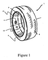
- Figure 1 displays a known arrangement for mounting a tire rotation sensor to the inner liner of a tire
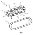
- FIG. 2 illustrates an exploded view of a Michelin Earthmover Management System (MEMS) platform patch for supporting tire environment sensors including, in accordance with the present technology, a piezoelectric tire rotation sensor;
- MEMS Michelin Earthmover Management System
- Figure 3 illustrates an alternative methodology for associating a piezoelectric tire rotation sensor with a MEMS platform patch and providing signal coupling to the MEMS platform;
- Figure 4 diagrammatically illustrates additional alternative methodologies for associating a piezoelectric tire rotation sensor with a MEMS platform patch and providing signal coupling to the MEMS platform.
- MEMS patches may be mounted internally of the tire on an internal sidewall portion of the tire and usually at prescribed distances from the lip of the bead of the tire. Such a location is not generally within the contact patch area of a tire, i.e. the portion of a tire that comes into contact with the surface over which the tire may roll.
- rotation sensitive sensors have been placed in the crown portion of a tire so as to, among other things, maximize the flexure to which the sensor is exposed upon tire rotation, thereby assisting in generating higher amplitude and, therefore, more easily detectable rotation signals.
- piezoelectric sensors in or on the sealed enclosure normally housing MEMS sensors and electronics and despite the normal positioning of such enclosure away from the contact patch portion of a tire, there, never the less, is sufficient flexure reaching the piezoelectric sensor to provide usable tire rotation responsive signals.
- the signal generated by piezoelectric sensors placed on or in MEMS enclosures can be electronically conditioned to provide a signal that can indicate tire rotations and possibly other parameters including, for example, acceleration, and other motion related parameters.
- Figure 1 illustrates a known configuration for counting tire revolutions using an integrated self-powered piezoelectric device 4 provided within a tire or wheel assembly. More specifically, Figure 1 depicts an exemplary perspective view of a pneumatic tire 1 characterized by a crown having an exterior tread portion 8, bead portions 10, and sidewall portions 6 extending between each tire bead 10 and the crown. An inner liner 15 is provided along the interior crown and sidewall surfaces, to which self-powered tire revolution counter 4 and/or other tire electronics may be mounted.
- Mounting tire revolution counter 4 on the inner liner 15 of a tire and, in particular, in the crown area of the tire can provide a practical source of tire rotation signals but such location also opens various areas of concern when such tire rotation signals are to be associated with other tire environment sensor signals from other sensors.
- a first area of concern arises from the physical placement of an additional sensor device within a tire. Additional costs including labor expense for mounting the tire rotation sensor may be avoided or minimized if the tire rotation sensor is combined with existing sensors.
- the present technology addresses this concern by associating a tire rotation sensor with existing sensors in various manners as will now be more fully described.
- a Michelin Earthmover Management System MEMS
- a piezoelectric tire rotation sensor 250 for supporting tire environment sensors including, in accordance with the present technology, a piezoelectric tire rotation sensor 250.
- MEMS Michelin Earthmover Management System
- the piezoelectric tire rotation sensor of the present technology may be combined with other tire environment sensors on a platform usable with many different types of tires and as such is not limited to the earthmover environment as illustratively discussed herein.
- the MEMS platform patch 200 provides an enclosure 210 that may be encased within an elastomeric enclosure 220 for ease of attachment to the inner surface of a tire to be monitored.
- Tire environment sensors as well as associated other elements including, but not limited to, temperature sensor 230, pressure sensor 240, and additional components including, but not limited to, a wireless transmitter 270 and a microprocessor or microcontroller 280, either of which may include memory portions for storage of various forms of data, may be mounted on a printed circuit board 260 in enclosure 210 of the MEMS platform patch 200.
- a battery 290 may provide power required for operation of the MEMS platform patch circuitry.
- tire rotations sensitive piezoelectric sensor 250 may also be mounted in enclosure 210 although other locations for the tire rotation sensitive piezoelectric sensor 250 are possible as will be discussed further later.
- battery 290 may be employed as a power source for the MEMS platform patch 200 but other configurations are possible including providing a rechargeable battery, possibly charged from energy harvested from piezoelectric sensor 250. Alternatively all operating power for the MEMS platform patch 200 might be derived from piezoelectric sensor 250.
- one acceptable location for the patch 200 is a location about eight inches from the lip of the bead 10 of a tire 1. It should be understood, however, that such position is not a limitation of the present technology but merely represents one acceptable position for attachment of the patch 200.
- a second area of concern with the provision of tire environment sensitive sensors relates to issues raised because of the ongoing practice of including various chemicals within an inflated tire. Some of these chemicals are intended, among other things, to provide physical protection for the tire.
- TireLife® a coolant, sealant, anti-oxidant, and rust inhibitor marketed by Fuller Brothers, Inc. of Olympia, WA, is an example of such a chemical used in conjunction with tires and wheels associated with large vehicles in the earthmover category.
- a side effect of such chemicals is that they act as contaminants with respect to included electronic sensors. Such contaminates may adversely effect operation of any sensors mounted within the tire.
- the present technology addresses this concern by providing methodologies for sealing piezoelectric tire rotation sensor 250 within an enclosure 210 previously provided for other tire environment sensors such as temperature sensor 230 and pressure sensor 240 as may be employed in the previously mentioned MEMS platform patch 200.
- a third area of concern with the provision of tire environment sensitive sensors relates to issues involving coupling of signals from various sensors to the MEMS platform and/or to external interrogators.
- the MEMS platform 200 may be configured so that signals are transmitted on a continuous or intermittent basis from wireless transmission circuitry (not shown) associated with the tire installed MEMS enclosure 210 to a vehicle mounted receiver or alternatively to a handheld interrogator or a drive by interrogator.
- Co-locating piezoelectric tire rotation sensor 250 with the MEMS platform significantly reduces signal-coupling problems when using the MEMS platform as the mechanism whereby tire rotation signals are conveyed to external receivers.
- coupling of signals from piezoelectric tire rotation sensor 250 to the MEMS platform may be carried out in a variety of ways.
- a particularly robust connection of tire rotation sensitive piezoelectric sensor 250 may be provided by physically mounting sensor 250 in MEMS enclosure 210 as illustrated in Fig. 2 .
- Such mounting methods also facilitate the desirable aspect of providing a completely sealed environment to protect the sensors and all other associated MEMS platform components from the contaminating effects of tire enclosed chemicals as previously discussed.
- Alternative mounting and signal coupling methodologies are contemplated, however, with respect to additional embodiments of the present technology.
- a tire rotations sensitive piezoelectric sensor 350 may be embedded on or within a MEMS platform patch 300.
- signals from the piezoelectric sensor 350 may be communicated to the tire electronics associated with the MEMS platform byway of direct wire connections 352,354.
- the piezoelectric sensor 350 may be affixed to the patch 300 before mounting the patch 300 to a tire and be configured with a wire pigtail to be attached to a thru-case connector on the MEMS enclosure.
- the pigtail could be attached to the MEMS enclosure and connected to the piezoelectric sensor contacts using solder or a conductive epoxy.
- a direct connection from the piezoelectric sensor 350 to the MEMS enclosure electronics may be established by providing the piezoelectric sensor 350 as an external package with leads 352, 354 configured as surface contacts configured to cooperate with matching spring loaded contacts on the MEMS patch 300.
- the electrical connection in such a configuration may be sealed or enhanced using a conductive rubber adhesive or grease.
- FIG. 4 there are diagrammatically illustrated additional embodiments of the present technology all involving non-contact methodologies for coupling signals from a piezoelectric sensor 450 embedded on or within a MEMS platform patch 400.
- Each of these additional embodiments of the preset technology contemplates wireless signal coupling methodologies for coupling signals from piezoelectric sensor 450 to the electronics contained within the MEMS platform patch 400, all of which are diagrammatically illustrated by representatively illustrated energy waves 460.
- the piezoelectric sensor 450 may be embedded on or within MEMS platform patch 400 along with an electronic circuit configured to transmit radio frequency (RF) on-off signals to a corresponding receiver (not shown) on the MEMS circuit board 260,
- RF radio frequency
- the RF transmission would require that operating power for the transmitter circuit be harvested from the piezoelectric sensor 450, but only minimal energy would need to be harvested as the transmission distance would generally be less than one inch and the corresponding receiver on the MEMS circuit board would only need to detect presence, or not, of the signal.
- a first variation of this embodiment of the present technology would replace the RF transmission methodology for transmitting signals from piezoelectric sensor 450 to the MEMS circuit board just discussed with a low frequency transmission.
- the power generated by deflection of the piezoelectric sensor 450 would be conditioned and discharged through an inductor.
- a matching inductor on the MEMS circuit board, in cooperation with the inductor coupled to the piezoelectric sensor 450 would function as an air-core transformer to couple signals from the piezoelectric sensor 450 to the electronics contained on the MEMS circuit board.
- yet another embodiment of the present technology is also diagrammatically represented in that the illustrated energy waves 460 are intended to represent also the use of optical transmission of signals from piezoelectric sensor 450 to the electronics contained on the MEMS circuit board 260.
- Such optical transmission may be configured in two different formats, one taking the form of an infra-red light emitting diode (LED) mounted with the piezoelectric sensor 450 and a corresponding photo-transistor mounted on the MEMS circuit board.
- LED infra-red light emitting diode
- a piezoelectric sensor may be configured such that a piezoelectric element is mounted on one side of a substrate while an electro-luminous panel is affixed to the other side of the substrate.
- the assembly may then be affixed to the patch 400 and oriented to allow transmission of optical signals to a photo-transistor mounted on the MEMS circuit board in a manner similar to that discussed with respect to the LED configured embodiment previously described.
Landscapes
- Physics & Mathematics (AREA)
- General Physics & Mathematics (AREA)
- Engineering & Computer Science (AREA)
- Mechanical Engineering (AREA)
- Measuring Fluid Pressure (AREA)
- Arrangements For Transmission Of Measured Signals (AREA)
- Force Measurement Appropriate To Specific Purposes (AREA)
Applications Claiming Priority (1)
| Application Number | Priority Date | Filing Date | Title |
|---|---|---|---|
| PCT/US2005/020698 WO2006135366A1 (en) | 2005-06-10 | 2005-06-10 | Use of piezoelectric sensor attached to electronics package housing |
Publications (3)
| Publication Number | Publication Date |
|---|---|
| EP1889025A1 EP1889025A1 (en) | 2008-02-20 |
| EP1889025A4 EP1889025A4 (en) | 2009-07-22 |
| EP1889025B1 true EP1889025B1 (en) | 2012-02-15 |
Family
ID=37532609
Family Applications (1)
| Application Number | Title | Priority Date | Filing Date |
|---|---|---|---|
| EP05760374A Expired - Lifetime EP1889025B1 (en) | 2005-06-10 | 2005-06-10 | Use of piezoelectric sensor attached to electronics package housing |
Country Status (7)
| Country | Link |
|---|---|
| US (1) | US7954370B2 (enExample) |
| EP (1) | EP1889025B1 (enExample) |
| JP (1) | JP5101497B2 (enExample) |
| CN (1) | CN101198854B (enExample) |
| AT (1) | ATE545528T1 (enExample) |
| TW (1) | TW200712470A (enExample) |
| WO (1) | WO2006135366A1 (enExample) |
Families Citing this family (28)
| Publication number | Priority date | Publication date | Assignee | Title |
|---|---|---|---|---|
| EP1856499B1 (en) * | 2005-03-11 | 2013-01-09 | Société de Technologie Michelin | Flex signature for tire condition |
| EP2085253B1 (en) * | 2006-11-14 | 2020-07-08 | Kabushiki Kaisha Bridgestone | Tires with sensor and methods for measuring tire strain amount |
| US7814781B2 (en) * | 2008-03-17 | 2010-10-19 | Infineon Technologies, Ag | Active and adaptive tire systems |
| US8841785B2 (en) * | 2008-04-15 | 2014-09-23 | Infineon Technologies Ag | Energy harvester |
| US8344868B2 (en) * | 2008-06-24 | 2013-01-01 | GM Global Technology Operations LLC | Maintenance of proper tire inflation pressure thru active material actuation |
| US8476808B2 (en) | 2008-08-29 | 2013-07-02 | Michelin Recherche Et Technique | 1-d tire apparatus |
| US8742265B2 (en) | 2008-08-29 | 2014-06-03 | Compagnie Generale Des Etablissements Michelin | 1-D tire patch apparatus and methodology |
| US8171791B2 (en) | 2009-05-13 | 2012-05-08 | Robert Bosch Gmbh | Rotation sensor with onboard power generation |
| US20120213036A1 (en) * | 2009-09-22 | 2012-08-23 | Atlas Elektronik Gmbh | Electroacoustic Transducer, in Particular Transmitting Transducer |
| CN102687180B (zh) * | 2009-09-30 | 2014-10-22 | 米其林研究和技术股份有限公司 | 用于轮胎温度测量的装置和方法 |
| JP5691275B2 (ja) * | 2010-07-20 | 2015-04-01 | 横浜ゴム株式会社 | タイヤの状態に関する情報を送信する送信装置およびタイヤ状態監視システム |
| US10000100B2 (en) | 2010-12-30 | 2018-06-19 | Compagnie Generale Des Etablissements Michelin | Piezoelectric based system and method for determining tire load |
| BR112013021034A2 (pt) * | 2011-02-16 | 2016-10-11 | 1814393 Ontario Inc | sistema de montagem de detecção de pressão de pneu |
| BR112014015412A8 (pt) * | 2011-12-29 | 2017-12-26 | Michelin Rech Tech | Sistema e método para a determinação de parâmetros de uniformidade do pneu de medições piezoelétricas na zona de contra-deflexão do pneu |
| US9304142B1 (en) * | 2013-03-12 | 2016-04-05 | A. Steve Gurganian | Energy harvesting zero-speed sensor device, method and system |
| BR112017011370A2 (pt) * | 2014-12-19 | 2017-12-26 | Bridgestone Americas Tire Operations Llc | remendo de fixação para dispositivos de montagem |
| DE102015107557A1 (de) | 2015-05-13 | 2016-11-17 | USound GmbH | Leiterplattenmodul mit durchgehender Aussparung sowie diesbezügliche Schallwandleranordnung sowie Herstellungsverfahren |
| JP2017071341A (ja) | 2015-10-08 | 2017-04-13 | 株式会社デンソー | タイヤマウントセンサおよびそれに用いられるセンサ装置 |
| US10243136B2 (en) * | 2016-08-22 | 2019-03-26 | Masoud Ghanbari | Piezoelectric energy harvesting system from vehicle's tires |
| CN107116978A (zh) * | 2017-05-17 | 2017-09-01 | 万力轮胎股份有限公司 | 一种可测温轮胎及一种车辆 |
| DE102017211744A1 (de) * | 2017-07-10 | 2019-01-10 | Zf Friedrichshafen Ag | Sensormodul für eine Kraftfahrzeugfelge |
| US10549587B2 (en) * | 2017-10-19 | 2020-02-04 | Infineon Technologies Ag | Method, component, tire-mounted TPMS module, TPMS system, and machine readable storage or computer program for determining time information of at least one contact patch event of a rolling tire, method for locating a tire |
| KR102127662B1 (ko) * | 2018-07-25 | 2020-06-29 | 한국타이어앤테크놀로지 주식회사 | 다점 시스템화되어 구성된 타이어용 센서 및 이를 구비한 타이어 |
| US10953710B2 (en) * | 2018-09-26 | 2021-03-23 | The Goodyear Tire & Rubber Company | Tire with printed strain sensors |
| US10960714B2 (en) * | 2018-09-26 | 2021-03-30 | The Goodyear Tire & Rubber Company | Tire with printed shear sensors |
| JP2024516636A (ja) * | 2021-04-30 | 2024-04-16 | テクスキャン インコーポレイテッド | 接触センサ |
| CN114969975B (zh) * | 2022-05-30 | 2023-03-24 | 北京理工大学 | 一种基于轮毂螺栓的车轮多维力测量方法和系统 |
| CN115830808B (zh) * | 2022-11-21 | 2025-01-24 | 西南交通大学 | 一种泥石流灾后抢险救援的实时监控装置及泥石流监控系统 |
Family Cites Families (29)
| Publication number | Priority date | Publication date | Assignee | Title |
|---|---|---|---|---|
| US3192419A (en) * | 1963-07-16 | 1965-06-29 | Hoover Co | Synchronous motor and mounting |
| US4510484A (en) | 1983-03-28 | 1985-04-09 | Imperial Clevite Inc. | Piezoelectric reed power supply for use in abnormal tire condition warning systems |
| WO1987002846A1 (en) * | 1985-10-29 | 1987-05-07 | Hopper William R | Touch sensitive indicating light |
| US4862486A (en) | 1987-11-16 | 1989-08-29 | Wing J Keith | Revolution counter attached to tires |
| US5457447A (en) | 1993-03-31 | 1995-10-10 | Motorola, Inc. | Portable power source and RF tag utilizing same |
| US5869189A (en) | 1994-04-19 | 1999-02-09 | Massachusetts Institute Of Technology | Composites for structural control |
| US5500065A (en) * | 1994-06-03 | 1996-03-19 | Bridgestone/Firestone, Inc. | Method for embedding a monitoring device within a tire during manufacture |
| US5749984A (en) | 1995-12-29 | 1998-05-12 | Michelin Recherche Et Technique S.A. | Tire monitoring system and method |
| GB9726594D0 (en) * | 1997-12-17 | 1998-02-18 | Sumitomo Rubber Ind | Sensor for a pneumatic tyre |
| AU4982999A (en) * | 1998-07-10 | 2000-02-01 | Goodyear Tire And Rubber Company, The | Self-powered tire revolution counter |
| MXPA01007973A (es) * | 1999-11-24 | 2003-09-11 | Michelin Rech Tech | Neumatico para vehiculos monitoreado y ensamble de reten de monitor. |
| US6688353B1 (en) * | 2000-03-31 | 2004-02-10 | Bridgestone/Firestone North American Tire, Llc | Attachment patch for mounting an electronic monitoring device to the inside of a pneumatic tire |
| US7331367B2 (en) * | 2000-03-31 | 2008-02-19 | Bridgestone Firestone North American Tire, Llc | Monitoring device and patch assembly |
| US7076999B1 (en) * | 2001-01-11 | 2006-07-18 | Lewis Lee Knox | Tire pressure monitoring system |
| FR2823148A1 (fr) * | 2001-04-09 | 2002-10-11 | Michelin Soc Tech | Dispositif de fixation d'un module electronique de surveillance sur un pneumatique |
| JP2003161638A (ja) * | 2001-11-28 | 2003-06-06 | Jigyo Sozo Kenkyusho:Kk | 回転信号発生装置及び回転検出システム |
| US7096727B2 (en) * | 2002-05-10 | 2006-08-29 | Michelin Recherche Et Technique S.A. | System and method for generating electric power from a rotating tire's mechanical energy |
| US6807853B2 (en) * | 2002-05-10 | 2004-10-26 | Michelin Recherche Et Technique S.A. | System and method for generating electric power from a rotating tire's mechanical energy using piezoelectric fiber composites |
| US6725713B2 (en) * | 2002-05-10 | 2004-04-27 | Michelin & Recherche Et Technique S.A. | System for generating electric power from a rotating tire's mechanical energy using reinforced piezoelectric materials |
| JP4281319B2 (ja) * | 2002-10-10 | 2009-06-17 | 株式会社ジェイテクト | 転がり軸受装置 |
| DE10253278B4 (de) | 2002-11-15 | 2009-10-08 | Continental Automotive Gmbh | Reifenmessung mit einem energieautark modulierten Backscatter-Transponder |
| JP2004281126A (ja) * | 2003-03-13 | 2004-10-07 | Matsushita Electric Ind Co Ltd | 二次電池電源装置 |
| US20050076982A1 (en) * | 2003-10-09 | 2005-04-14 | Metcalf Arthur Richard | Post patch assembly for mounting devices in a tire interior |
| KR100555659B1 (ko) * | 2003-12-22 | 2006-03-03 | 삼성전자주식회사 | 자가발전형 센싱 모듈 및 그것을 사용하는 타이어 공기압모니터링 시스템 |
| US7196617B2 (en) * | 2004-04-19 | 2007-03-27 | Michelin Recherche Et Technique S.A. | Graduated stiffness for electrical connections in tires |
| DE102004026035B4 (de) * | 2004-05-27 | 2008-02-07 | Siemens Ag | Verfahren und Vorrichtung zur Steuerung des Betriebes einer einem Fahrzeugrad zugeordneten Radelektronik |
| US7138911B2 (en) * | 2004-08-04 | 2006-11-21 | Michelin Recherche Et Technique S.A. | Power conversion from piezoelectric source with multi-stage storage |
| US7343787B2 (en) * | 2005-05-19 | 2008-03-18 | Oguzhan Oflaz | Piezoelectric tire sensor and method |
| KR100817319B1 (ko) * | 2006-11-01 | 2008-03-27 | 한국과학기술연구원 | 이동형 기기의 전력 발생장치 및 이를 구비한자가발전시스템 |
-
2005
- 2005-06-10 JP JP2008515677A patent/JP5101497B2/ja not_active Expired - Fee Related
- 2005-06-10 AT AT05760374T patent/ATE545528T1/de active
- 2005-06-10 US US11/916,585 patent/US7954370B2/en not_active Expired - Fee Related
- 2005-06-10 WO PCT/US2005/020698 patent/WO2006135366A1/en not_active Ceased
- 2005-06-10 EP EP05760374A patent/EP1889025B1/en not_active Expired - Lifetime
- 2005-06-10 CN CN2005800500726A patent/CN101198854B/zh not_active Expired - Lifetime
-
2006
- 2006-05-26 TW TW095118862A patent/TW200712470A/zh unknown
Also Published As
| Publication number | Publication date |
|---|---|
| EP1889025A4 (en) | 2009-07-22 |
| CN101198854B (zh) | 2012-06-20 |
| US7954370B2 (en) | 2011-06-07 |
| TW200712470A (en) | 2007-04-01 |
| EP1889025A1 (en) | 2008-02-20 |
| JP2008545986A (ja) | 2008-12-18 |
| US20080289407A1 (en) | 2008-11-27 |
| CN101198854A (zh) | 2008-06-11 |
| WO2006135366A1 (en) | 2006-12-21 |
| JP5101497B2 (ja) | 2012-12-19 |
| ATE545528T1 (de) | 2012-03-15 |
Similar Documents
| Publication | Publication Date | Title |
|---|---|---|
| EP1889025B1 (en) | Use of piezoelectric sensor attached to electronics package housing | |
| CN1078143C (zh) | 感知和传送车辆轮胎参数的发送应答器和传感器装置 | |
| US7726184B2 (en) | Surface acoustic wave sensor and package | |
| JP4809211B2 (ja) | 回転するタイヤの静電気から電力を回収するためのシステム及び方法 | |
| EP1870261B1 (en) | Tire parameter monitoring system with inductive power source | |
| CN1331689C (zh) | 利用增强压电材料从旋转轮胎机械能量中产生电能的系统 | |
| JP4034316B2 (ja) | タイヤの技術的状態を監視する装置 | |
| US7186308B2 (en) | System and method for providing tire electronics mounting patches | |
| US7730772B2 (en) | Surface acoustic wave sensor and package | |
| US8166809B2 (en) | In-tire multi-element piezoelectric sensor | |
| US20050076982A1 (en) | Post patch assembly for mounting devices in a tire interior | |
| US7171849B2 (en) | Sensor module | |
| JP2006151372A (ja) | 回転するタイヤの機械エネルギーから電力を発生するシステム及び方法 | |
| JP2008545986A5 (enExample) | ||
| KR20080077203A (ko) | 압력 센서 설치 방법, 압력 센서를 설치한 타이어 및 휠 및타이어 압력 검지 장치 | |
| EP1897078B1 (en) | Inductive coupling of pulses from piezoelectric device |
Legal Events
| Date | Code | Title | Description |
|---|---|---|---|
| PUAI | Public reference made under article 153(3) epc to a published international application that has entered the european phase |
Free format text: ORIGINAL CODE: 0009012 |
|
| 17P | Request for examination filed |
Effective date: 20071205 |
|
| AK | Designated contracting states |
Kind code of ref document: A1 Designated state(s): AT BE BG CH CY CZ DE DK EE ES FI FR GB GR HU IE IS IT LI LT LU MC NL PL PT RO SE SI SK TR |
|
| RIN1 | Information on inventor provided before grant (corrected) |
Inventor name: SINNETT, JAY, C. Inventor name: TYNDALL, PATRICK, A. Inventor name: GRAMLING, FRANK |
|
| DAX | Request for extension of the european patent (deleted) | ||
| A4 | Supplementary search report drawn up and despatched |
Effective date: 20090618 |
|
| REG | Reference to a national code |
Ref country code: DE Ref legal event code: R079 Ref document number: 602005032690 Country of ref document: DE Free format text: PREVIOUS MAIN CLASS: G01M0017020000 Ipc: B60C0023040000 |
|
| GRAP | Despatch of communication of intention to grant a patent |
Free format text: ORIGINAL CODE: EPIDOSNIGR1 |
|
| RIC1 | Information provided on ipc code assigned before grant |
Ipc: B60C 23/04 20060101AFI20110707BHEP |
|
| GRAS | Grant fee paid |
Free format text: ORIGINAL CODE: EPIDOSNIGR3 |
|
| GRAA | (expected) grant |
Free format text: ORIGINAL CODE: 0009210 |
|
| AK | Designated contracting states |
Kind code of ref document: B1 Designated state(s): AT BE BG CH CY CZ DE DK EE ES FI FR GB GR HU IE IS IT LI LT LU MC NL PL PT RO SE SI SK TR |
|
| REG | Reference to a national code |
Ref country code: GB Ref legal event code: FG4D Ref country code: CH Ref legal event code: EP |
|
| REG | Reference to a national code |
Ref country code: IE Ref legal event code: FG4D |
|
| REG | Reference to a national code |
Ref country code: AT Ref legal event code: REF Ref document number: 545528 Country of ref document: AT Kind code of ref document: T Effective date: 20120315 |
|
| REG | Reference to a national code |
Ref country code: DE Ref legal event code: R096 Ref document number: 602005032690 Country of ref document: DE Effective date: 20120419 |
|
| REG | Reference to a national code |
Ref country code: NL Ref legal event code: VDEP Effective date: 20120215 |
|
| LTIE | Lt: invalidation of european patent or patent extension |
Effective date: 20120215 |
|
| PG25 | Lapsed in a contracting state [announced via postgrant information from national office to epo] |
Ref country code: LT Free format text: LAPSE BECAUSE OF FAILURE TO SUBMIT A TRANSLATION OF THE DESCRIPTION OR TO PAY THE FEE WITHIN THE PRESCRIBED TIME-LIMIT Effective date: 20120215 Ref country code: IS Free format text: LAPSE BECAUSE OF FAILURE TO SUBMIT A TRANSLATION OF THE DESCRIPTION OR TO PAY THE FEE WITHIN THE PRESCRIBED TIME-LIMIT Effective date: 20120615 Ref country code: NL Free format text: LAPSE BECAUSE OF FAILURE TO SUBMIT A TRANSLATION OF THE DESCRIPTION OR TO PAY THE FEE WITHIN THE PRESCRIBED TIME-LIMIT Effective date: 20120215 |
|
| PG25 | Lapsed in a contracting state [announced via postgrant information from national office to epo] |
Ref country code: GR Free format text: LAPSE BECAUSE OF FAILURE TO SUBMIT A TRANSLATION OF THE DESCRIPTION OR TO PAY THE FEE WITHIN THE PRESCRIBED TIME-LIMIT Effective date: 20120516 Ref country code: BE Free format text: LAPSE BECAUSE OF FAILURE TO SUBMIT A TRANSLATION OF THE DESCRIPTION OR TO PAY THE FEE WITHIN THE PRESCRIBED TIME-LIMIT Effective date: 20120215 Ref country code: FI Free format text: LAPSE BECAUSE OF FAILURE TO SUBMIT A TRANSLATION OF THE DESCRIPTION OR TO PAY THE FEE WITHIN THE PRESCRIBED TIME-LIMIT Effective date: 20120215 Ref country code: PL Free format text: LAPSE BECAUSE OF FAILURE TO SUBMIT A TRANSLATION OF THE DESCRIPTION OR TO PAY THE FEE WITHIN THE PRESCRIBED TIME-LIMIT Effective date: 20120215 Ref country code: PT Free format text: LAPSE BECAUSE OF FAILURE TO SUBMIT A TRANSLATION OF THE DESCRIPTION OR TO PAY THE FEE WITHIN THE PRESCRIBED TIME-LIMIT Effective date: 20120615 |
|
| REG | Reference to a national code |
Ref country code: AT Ref legal event code: MK05 Ref document number: 545528 Country of ref document: AT Kind code of ref document: T Effective date: 20120215 |
|
| PG25 | Lapsed in a contracting state [announced via postgrant information from national office to epo] |
Ref country code: CY Free format text: LAPSE BECAUSE OF FAILURE TO SUBMIT A TRANSLATION OF THE DESCRIPTION OR TO PAY THE FEE WITHIN THE PRESCRIBED TIME-LIMIT Effective date: 20120215 |
|
| PG25 | Lapsed in a contracting state [announced via postgrant information from national office to epo] |
Ref country code: CZ Free format text: LAPSE BECAUSE OF FAILURE TO SUBMIT A TRANSLATION OF THE DESCRIPTION OR TO PAY THE FEE WITHIN THE PRESCRIBED TIME-LIMIT Effective date: 20120215 Ref country code: RO Free format text: LAPSE BECAUSE OF FAILURE TO SUBMIT A TRANSLATION OF THE DESCRIPTION OR TO PAY THE FEE WITHIN THE PRESCRIBED TIME-LIMIT Effective date: 20120215 Ref country code: EE Free format text: LAPSE BECAUSE OF FAILURE TO SUBMIT A TRANSLATION OF THE DESCRIPTION OR TO PAY THE FEE WITHIN THE PRESCRIBED TIME-LIMIT Effective date: 20120215 Ref country code: SI Free format text: LAPSE BECAUSE OF FAILURE TO SUBMIT A TRANSLATION OF THE DESCRIPTION OR TO PAY THE FEE WITHIN THE PRESCRIBED TIME-LIMIT Effective date: 20120215 Ref country code: DK Free format text: LAPSE BECAUSE OF FAILURE TO SUBMIT A TRANSLATION OF THE DESCRIPTION OR TO PAY THE FEE WITHIN THE PRESCRIBED TIME-LIMIT Effective date: 20120215 Ref country code: SE Free format text: LAPSE BECAUSE OF FAILURE TO SUBMIT A TRANSLATION OF THE DESCRIPTION OR TO PAY THE FEE WITHIN THE PRESCRIBED TIME-LIMIT Effective date: 20120215 |
|
| PG25 | Lapsed in a contracting state [announced via postgrant information from national office to epo] |
Ref country code: SK Free format text: LAPSE BECAUSE OF FAILURE TO SUBMIT A TRANSLATION OF THE DESCRIPTION OR TO PAY THE FEE WITHIN THE PRESCRIBED TIME-LIMIT Effective date: 20120215 |
|
| PLBE | No opposition filed within time limit |
Free format text: ORIGINAL CODE: 0009261 |
|
| STAA | Information on the status of an ep patent application or granted ep patent |
Free format text: STATUS: NO OPPOSITION FILED WITHIN TIME LIMIT |
|
| 26N | No opposition filed |
Effective date: 20121116 |
|
| PG25 | Lapsed in a contracting state [announced via postgrant information from national office to epo] |
Ref country code: AT Free format text: LAPSE BECAUSE OF FAILURE TO SUBMIT A TRANSLATION OF THE DESCRIPTION OR TO PAY THE FEE WITHIN THE PRESCRIBED TIME-LIMIT Effective date: 20120215 Ref country code: MC Free format text: LAPSE BECAUSE OF NON-PAYMENT OF DUE FEES Effective date: 20120630 |
|
| REG | Reference to a national code |
Ref country code: CH Ref legal event code: PL |
|
| REG | Reference to a national code |
Ref country code: CH Ref legal event code: PL |
|
| GBPC | Gb: european patent ceased through non-payment of renewal fee |
Effective date: 20120610 |
|
| REG | Reference to a national code |
Ref country code: DE Ref legal event code: R097 Ref document number: 602005032690 Country of ref document: DE Effective date: 20121116 |
|
| REG | Reference to a national code |
Ref country code: IE Ref legal event code: MM4A |
|
| PG25 | Lapsed in a contracting state [announced via postgrant information from national office to epo] |
Ref country code: LI Free format text: LAPSE BECAUSE OF NON-PAYMENT OF DUE FEES Effective date: 20120630 Ref country code: ES Free format text: LAPSE BECAUSE OF FAILURE TO SUBMIT A TRANSLATION OF THE DESCRIPTION OR TO PAY THE FEE WITHIN THE PRESCRIBED TIME-LIMIT Effective date: 20120526 Ref country code: CH Free format text: LAPSE BECAUSE OF NON-PAYMENT OF DUE FEES Effective date: 20120630 Ref country code: GB Free format text: LAPSE BECAUSE OF NON-PAYMENT OF DUE FEES Effective date: 20120610 Ref country code: IE Free format text: LAPSE BECAUSE OF NON-PAYMENT OF DUE FEES Effective date: 20120610 |
|
| PG25 | Lapsed in a contracting state [announced via postgrant information from national office to epo] |
Ref country code: BG Free format text: LAPSE BECAUSE OF FAILURE TO SUBMIT A TRANSLATION OF THE DESCRIPTION OR TO PAY THE FEE WITHIN THE PRESCRIBED TIME-LIMIT Effective date: 20120515 |
|
| PG25 | Lapsed in a contracting state [announced via postgrant information from national office to epo] |
Ref country code: TR Free format text: LAPSE BECAUSE OF FAILURE TO SUBMIT A TRANSLATION OF THE DESCRIPTION OR TO PAY THE FEE WITHIN THE PRESCRIBED TIME-LIMIT Effective date: 20120215 |
|
| PG25 | Lapsed in a contracting state [announced via postgrant information from national office to epo] |
Ref country code: LU Free format text: LAPSE BECAUSE OF NON-PAYMENT OF DUE FEES Effective date: 20120610 |
|
| PG25 | Lapsed in a contracting state [announced via postgrant information from national office to epo] |
Ref country code: HU Free format text: LAPSE BECAUSE OF FAILURE TO SUBMIT A TRANSLATION OF THE DESCRIPTION OR TO PAY THE FEE WITHIN THE PRESCRIBED TIME-LIMIT Effective date: 20050610 |
|
| REG | Reference to a national code |
Ref country code: FR Ref legal event code: PLFP Year of fee payment: 12 |
|
| REG | Reference to a national code |
Ref country code: FR Ref legal event code: PLFP Year of fee payment: 13 |
|
| REG | Reference to a national code |
Ref country code: FR Ref legal event code: PLFP Year of fee payment: 14 |
|
| REG | Reference to a national code |
Ref country code: DE Ref legal event code: R081 Ref document number: 602005032690 Country of ref document: DE Owner name: COMPAGNIE GENERALE DES ETABLISSEMENTS MICHELIN, FR Free format text: FORMER OWNERS: SOCIETE DE TECHNOLOGIE MICHELIN, CLERMONT-FERRAND, FR; MICHELIN RECHERCHE ET TECHNIQUE S.A., GRANGES-PACCOT, CH |
|
| PGFP | Annual fee paid to national office [announced via postgrant information from national office to epo] |
Ref country code: DE Payment date: 20240619 Year of fee payment: 20 |
|
| PGFP | Annual fee paid to national office [announced via postgrant information from national office to epo] |
Ref country code: FR Payment date: 20240628 Year of fee payment: 20 |
|
| PGFP | Annual fee paid to national office [announced via postgrant information from national office to epo] |
Ref country code: IT Payment date: 20240625 Year of fee payment: 20 |
|
| REG | Reference to a national code |
Ref country code: DE Ref legal event code: R071 Ref document number: 602005032690 Country of ref document: DE |