EP1888943B1 - Transmission with orbital gears - Google Patents
Transmission with orbital gears Download PDFInfo
- Publication number
- EP1888943B1 EP1888943B1 EP06747549A EP06747549A EP1888943B1 EP 1888943 B1 EP1888943 B1 EP 1888943B1 EP 06747549 A EP06747549 A EP 06747549A EP 06747549 A EP06747549 A EP 06747549A EP 1888943 B1 EP1888943 B1 EP 1888943B1
- Authority
- EP
- European Patent Office
- Prior art keywords
- wheel
- transmission according
- rotary shaft
- rotor
- transmission
- Prior art date
- Legal status (The legal status is an assumption and is not a legal conclusion. Google has not performed a legal analysis and makes no representation as to the accuracy of the status listed.)
- Not-in-force
Links
Images


Classifications
-
- F—MECHANICAL ENGINEERING; LIGHTING; HEATING; WEAPONS; BLASTING
- F01—MACHINES OR ENGINES IN GENERAL; ENGINE PLANTS IN GENERAL; STEAM ENGINES
- F01C—ROTARY-PISTON OR OSCILLATING-PISTON MACHINES OR ENGINES
- F01C17/00—Arrangements for drive of co-operating members, e.g. for rotary piston and casing
- F01C17/06—Arrangements for drive of co-operating members, e.g. for rotary piston and casing using cranks, universal joints or similar elements
-
- F—MECHANICAL ENGINEERING; LIGHTING; HEATING; WEAPONS; BLASTING
- F01—MACHINES OR ENGINES IN GENERAL; ENGINE PLANTS IN GENERAL; STEAM ENGINES
- F01C—ROTARY-PISTON OR OSCILLATING-PISTON MACHINES OR ENGINES
- F01C17/00—Arrangements for drive of co-operating members, e.g. for rotary piston and casing
- F01C17/02—Arrangements for drive of co-operating members, e.g. for rotary piston and casing of toothed-gearing type
-
- F—MECHANICAL ENGINEERING; LIGHTING; HEATING; WEAPONS; BLASTING
- F04—POSITIVE - DISPLACEMENT MACHINES FOR LIQUIDS; PUMPS FOR LIQUIDS OR ELASTIC FLUIDS
- F04C—ROTARY-PISTON, OR OSCILLATING-PISTON, POSITIVE-DISPLACEMENT MACHINES FOR LIQUIDS; ROTARY-PISTON, OR OSCILLATING-PISTON, POSITIVE-DISPLACEMENT PUMPS
- F04C15/00—Component parts, details or accessories of machines, pumps or pumping installations, not provided for in groups F04C2/00 - F04C14/00
- F04C15/0057—Driving elements, brakes, couplings, transmission specially adapted for machines or pumps
- F04C15/0061—Means for transmitting movement from the prime mover to driven parts of the pump, e.g. clutches, couplings, transmissions
- F04C15/0065—Means for transmitting movement from the prime mover to driven parts of the pump, e.g. clutches, couplings, transmissions for eccentric movement
-
- F—MECHANICAL ENGINEERING; LIGHTING; HEATING; WEAPONS; BLASTING
- F04—POSITIVE - DISPLACEMENT MACHINES FOR LIQUIDS; PUMPS FOR LIQUIDS OR ELASTIC FLUIDS
- F04C—ROTARY-PISTON, OR OSCILLATING-PISTON, POSITIVE-DISPLACEMENT MACHINES FOR LIQUIDS; ROTARY-PISTON, OR OSCILLATING-PISTON, POSITIVE-DISPLACEMENT PUMPS
- F04C2/00—Rotary-piston machines or pumps
- F04C2/08—Rotary-piston machines or pumps of intermeshing-engagement type, i.e. with engagement of co-operating members similar to that of toothed gearing
- F04C2/10—Rotary-piston machines or pumps of intermeshing-engagement type, i.e. with engagement of co-operating members similar to that of toothed gearing of internal-axis type with the outer member having more teeth or tooth-equivalents, e.g. rollers, than the inner member
- F04C2/107—Rotary-piston machines or pumps of intermeshing-engagement type, i.e. with engagement of co-operating members similar to that of toothed gearing of internal-axis type with the outer member having more teeth or tooth-equivalents, e.g. rollers, than the inner member with helical teeth
- F04C2/1071—Rotary-piston machines or pumps of intermeshing-engagement type, i.e. with engagement of co-operating members similar to that of toothed gearing of internal-axis type with the outer member having more teeth or tooth-equivalents, e.g. rollers, than the inner member with helical teeth the inner and outer member having a different number of threads and one of the two being made of elastic materials, e.g. Moineau type
- F04C2/1073—Rotary-piston machines or pumps of intermeshing-engagement type, i.e. with engagement of co-operating members similar to that of toothed gearing of internal-axis type with the outer member having more teeth or tooth-equivalents, e.g. rollers, than the inner member with helical teeth the inner and outer member having a different number of threads and one of the two being made of elastic materials, e.g. Moineau type where one member is stationary while the other member rotates and orbits
-
- F—MECHANICAL ENGINEERING; LIGHTING; HEATING; WEAPONS; BLASTING
- F16—ENGINEERING ELEMENTS AND UNITS; GENERAL MEASURES FOR PRODUCING AND MAINTAINING EFFECTIVE FUNCTIONING OF MACHINES OR INSTALLATIONS; THERMAL INSULATION IN GENERAL
- F16H—GEARING
- F16H3/00—Toothed gearings for conveying rotary motion with variable gear ratio or for reversing rotary motion
- F16H3/44—Toothed gearings for conveying rotary motion with variable gear ratio or for reversing rotary motion using gears having orbital motion
- F16H3/72—Toothed gearings for conveying rotary motion with variable gear ratio or for reversing rotary motion using gears having orbital motion with a secondary drive, e.g. regulating motor, in order to vary speed continuously
-
- F—MECHANICAL ENGINEERING; LIGHTING; HEATING; WEAPONS; BLASTING
- F16—ENGINEERING ELEMENTS AND UNITS; GENERAL MEASURES FOR PRODUCING AND MAINTAINING EFFECTIVE FUNCTIONING OF MACHINES OR INSTALLATIONS; THERMAL INSULATION IN GENERAL
- F16H—GEARING
- F16H37/00—Combinations of mechanical gearings, not provided for in groups F16H1/00 - F16H35/00
- F16H37/02—Combinations of mechanical gearings, not provided for in groups F16H1/00 - F16H35/00 comprising essentially only toothed or friction gearings
- F16H37/06—Combinations of mechanical gearings, not provided for in groups F16H1/00 - F16H35/00 comprising essentially only toothed or friction gearings with a plurality of driving or driven shafts; with arrangements for dividing torque between two or more intermediate shafts
- F16H37/08—Combinations of mechanical gearings, not provided for in groups F16H1/00 - F16H35/00 comprising essentially only toothed or friction gearings with a plurality of driving or driven shafts; with arrangements for dividing torque between two or more intermediate shafts with differential gearing
- F16H37/0833—Combinations of mechanical gearings, not provided for in groups F16H1/00 - F16H35/00 comprising essentially only toothed or friction gearings with a plurality of driving or driven shafts; with arrangements for dividing torque between two or more intermediate shafts with differential gearing with arrangements for dividing torque between two or more intermediate shafts, i.e. with two or more internal power paths
Definitions
- the invention relates to a transmission for coupling drive elements, in particular a transmission for coupling a first drive element which is a shaft rotating about its centerline and a second drive element which circularly revolves around that centerline with rotation with respect to its own centerline.
- Such a transmission is, for instance, used for driving a so-called progressing cavity pump (PC pump), in which a helical rotor revolves rotatingly about its own longitudinal axis around the centerline of a stator in which the rotor is eccentrically received. Per revolving movement around the stator axis, the rotor of the PC pump rotates once in opposite direction about its own axis.
- PC pump progressing cavity pump
- this transmission is typically designed as a cardan shaft transmission.
- a drawback of this cardan shaft transmission is that it causes the rotor to exert a relatively large radial force on the stator near the coupled end. Further, a drawback of the known manner of driving is that the rotor is guided with the aid of the stator surface.
- the PC pump In practice, this causes the PC pump to be subject to relatively strong wear. Further, the stator is designed from relatively elastic material, such as rubber. As a result, in practice, the use of the PC pump has remained limited to pumping thick liquid, such as cement or pastes.
- the invention contemplates a transmission for realizing above-mentioned transmission, with which, while maintaining the advantages, the drawbacks mentioned can be obviated.
- the invention further contemplates a transmission which can form a variator between two drive elements.
- the invention provides a transmission, comprising a rotary shaft for coupling with a first drive element, provided with a wheel supported eccentrically and freely rotatably on the shaft for coupling with a second drive element, further comprising a ring arranged concentrically and rotatably with respect to the rotary shaft, which ring is provided with a first tread cooperating which the tread of the wheel and is provided with a second tread cooperating with the tread of an auxiliary drive element, such that rotation of the rotary shaft results in a corresponding circular revolving movement of the wheel around the centerline of the rotary shaft, while rotation of the wheel about its own axis depends on the rotation of the rotary shaft and on the rotation of the ring about the centerline of the rotary shaft.
- the circumference of the inner tread of the ring can, as it were, relatively be increased or decreased, so that the rotation of the wheel can be set as desired.
- the first and second tread may, for instance, be designed as internal toothings and external toothings of the ring, respectively, but may also be external toothings or internal toothings of different diameters.
- the wheel is a toothed wheel and the ring is a toothed ring cooperating with the toothed wheel and a second toothing cooperating with a toothing of the auxiliary drive element.
- the treads are toothings, an accurate transmission can be realized with a good and efficient force transmission.
- the auxiliary drive element may be coupled with the rotary shaft via a transmission, for instance with a fixed transmission ratio.
- a transmission with fixed transmission ratio may, for instance, be realized with the aid of a toothed wheel transmission between the external toothing of a toothed ring and the rotary shaft.
- one revolution of the rotary shaft results in one opposite revolution of the toothed wheel around its own axis.
- the auxiliary drive element By coupling the auxiliary drive element with a servomotor, for instance by designing the auxiliary drive element as a worm wheel driven via an auxiliary electric motor, which worm wheel engages the external toothing of the toothed ring, the transmission ratio can be chosen freely. In this manner, the transmission can be used as a variator.
- the wheel may then, for instance, via a cardan shaft transmission, be coupled with an input shaft of a second drive element whose rotary shaft extends co-parallel to the rotary shaft of the first drive element.
- the wheel in a same transmission ration as with the ring, cooperates with a tread of a further auxiliary ring arranged next to the ring, concentrically with the rotary shaft.
- a toothing of the wheel cooperates with the toothing of the auxiliary ring with the same distance of the line of action to the rotary shaft of the first drive element as the line of action between wheel and ring.
- a same transmission ratio may also be realized with the aid of, for instance, eccentric toothed wheels cooperating with oval toothed wheels.
- Such an auxiliary ring may be designed as an end auxiliary ring supporting a further rotary shaft arranged co-parallel to the rotary shaft and providing the coupling with the second drive element.
- the ring may be designed as an intermediate auxiliary ring provided with a further auxiliary wheel arranged eccentrically and freely rotatably, so that, by repeating the construction, a multi-stage variator can be formed.
- a second ring arranged concentrically and rotatably with respect to the rotary shaft may be provided, which second ring is provided with an internal tread cooperating with the tread of the auxiliary wheel and is provided with an external tread cooperating with the tread of a second auxiliary drive element.
- the auxiliary wheel may also cooperate with the internal tread of a second auxiliary ring forming an end auxiliary ring or an auxiliary ring forming, in turn, a second intermediate auxiliary ring for making a third stage, etc.
- auxiliary drive elements By driving the first and second auxiliary drive elements with one or more servomotors, a variator can be created with two control stages.
- the auxiliary drive elements may also be used for realizing branches or inputs with mutually different rotational speeds.
- one or more double bearings are provided which are each built up from a cylindrical first bearing eccentrically received in a second cylindrical bearing.
- the bearings are not only designed for absorbing a radial force component, but also for absorbing an axial force component, for instance by designing the bearings as angular ball bearings.
- a bearing shield By sealing the surfaces in which the bearings are located, a bearing shield can be formed.
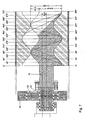
- Such a double bearing and/or bearing shield may be used in an advantageous manner for bearing-mounting the rotating revolving movement of the wheel or auxiliary wheel, but may, as will be explained hereinbelow, even in itself be used in an advantageous manner in a different environment, for instance for bearing-mounting a helical rotor of a PC pump conventionally driven with a cardan shaft transmission, Oldham coupling or flexible coupling.
- the transmission is coupled with a helical rotor so that a PC pump or PC motor can be formed.
- the wheel is preferably coupled with the rotor which is provided with at least one helical winding extending around a rotor centerline which is received in a stator.
- the revolution and rotation of the rotor can be driven without exerting radial force on the stator and, further, the rotor does not need to be guided by the stator surface anymore, but it can carry out an independent movement.
- Rotor and stator may both be manufactured from relatively stiff material, in particular steel. Further, between rotor and stator, an accurate fit may be provided, so that the PC pump can be used as a compressor, or even as a motor.
- the stator has a thin-walled design.
- the stator may be provided with ribs extending in axial direction which can act as cooling ribs and/or stiffening ribs.
- the rotor By designing the rotor to be thin-walled, what can be achieved is that it can be constructed to be relatively strong and light, while, further, there is a possibility of receiving the rotor in the cooling circuit.
- the rotor can further be stiffened by receiving an internal profile in the rotor, for instance a helically wound box profile.
- a multi-stage pump or compressor By having the diameter of stator and rotor shift along the centerline, a multi-stage pump or compressor can be formed.
- a mixing pump When, at the location of such a shift, a supply channel is provided which opens into the receiving opening, a mixing pump can be realized in an elegant manner.
- the rotor can be a displacement body of a pump, compressor or mixer.
- the rotor can be a displaced body of a motor, for instance a hydraulic motor or an internal combustion engine.
- the parts of the sidewalls of the rotor running straight in cross section may further be provided with cavities located below the surface for realizing a resilient seal.
- Such cavities may, for instance, be filled with a liquid material, allowing a sealing protuberance to be created on the low-pressure side of the stator.
- Such a cavity may, for instance, be formed by receiving a mounting slot in the stator wall, in which a hollow core strip optionally filled with liquid material can be received.
- the cooperating surfaces of rotor and stator may also be provided with a lining material, such as a chemically resistant material, a wear-resistant and/or friction-reducing material.
- lining material examples include, for instance, PTFE or ceramic material.
- the transmission 1 comprises a rotary shaft 2 arranged rotatably with respect to a centerline H1.
- the rotary shaft is designed for coupling with a first drive element 3, for instance an electric motor.
- the rotary shaft 2 is provided with a toothed wheel 4 supported eccentrically, with eccentricity e, on the rotary shaft 2.
- the toothed wheel is supported on the rotary shaft 2 so as to be freely rotatable with respect to its own centerline H2.
- the toothed wheel 4 is designed for coupling with a second drive element 5, which is, for instance, connected with the rotor 6 of a PC pump 7.
- the transmission 1 further comprises a toothed ring 8 arranged concentrically and freely rotatably about the centerline H1 of the rotary shaft 2.
- the toothed ring 8 is provided with a first toothing 9 cooperating with the toothing 10 of the toothed wheel 4.
- the toothed ring 8 is further provided with a second toothing 11 cooperating with the toothing 12 of an auxiliary drive element 13.
- the auxiliary drive element is a toothed wheel coupled with the rotary shaft 2 via a fixed transmission ratio.
- the rotary shaft supports a toothed wheel 35 arranged so as to rotate along about centerline H1, which toothed wheel 35 cooperates with a toothed wheel 36 which in turn rotates along with the auxiliary drive element 13 designed as a toothed wheel about an axis of rotation H4.
- the transmission ratio between auxiliary drive element 13 and rotably shaft 2 is such that one revolution of the rotary shaft 2 results in an opposite revolution of the toothed wheel 4 around the centerline H2 of its own shaft.
- the toothed wheel 4 is mounted on an eccentric projection 14 of the rotary shaft 2, which is located inside the shaft diameter.
- a crank projecting with respect to the shaft, on which the toothed wheel can be mounted is also possible.
- the rotor 6 of the PC pump is provided with one helical winding 15 extending around a rotor centerline H3.
- the rotor centerline runs substantially parallel, with eccentric intermediate distance e, with respect to the centerline H1 of the rotary shaft 2, which coincides with the centerline of the stator 16.
- the rotor 6 is received in a receiving opening 17 of the stator 16.
- the receiving opening 17 is provided with two helical cavities 18 extending substantially parallel at eccentric distance e with respect to the centerline H1 of the rotary shaft 2, which cavities are interconnected via the center area 19 of the stator 16.
- the rotor 6 and the stator 16 are manufactured from steel or another similar, relatively stiff material.
- the cooperating surfaces of rotor and stator are provided with a lining, for instance a ceramic coating.
- rotor and stator are provided with a cross section shifting from a smaller diameter D1 to a larger diameter D2, so that the pump comprises two steps.
- a channel which opens into the receiving opening 17 in the stator is provided, this channel can be used for feeding a substance to be mixed to the substrate to be pumped.
- Fig. 3 shows that the PC pump 7 is provided with a cement slurry, input 20 from which cement slurry is suctioned out with the aid of a displacement space moving as a result of the rotor 6 moving in the stator receiving opening and is pressed to a press output 21.
- a bearing shield 30 One side wall of the cement slurry input 20 is formed by a bearing shield 30.
- the bearing shield 30 is shown in more detail.
- the bearing shield bearing-mounts the rotating revolving movement of the rotor 6 and the toothed wheel 4 coupled therewith.
- the bearing shield is built up from a cylindrical first bearing 31 eccentrically received in a second cylindrical bearing 32.
- the bearings 31 are each designed as double angular ball bearings.
- the surfaces in which the bearings are located are sealed. In the embodiment as shown in Fig.
- the double bearing can be used in an advantageous manner for a progressing cavity apparatus in which a helical rotor revolves rotatingly about its own longitudinal axis around the centerline of a stator in which the rotor is received eccentrically by guiding the side of the rotor which the transmission engages with the aid of an eccentric double bearing.
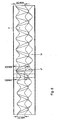
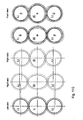
- Fig. 4 shows how the stator proceeds through the successive steps when making one complete revolution.
- the stator 16 rotates once in opposite direction about its own centerline H3.
- the toothed ring 8 is rotated to keep the rotation of the toothed wheel 4 about its centerline H2 limited to one complete rotation.
- the rotor can be received in the stator with little play, so that use as a compressor or mud motor, or even internal combustion engine, is possible.
- the free end of the rotor is then preferably bearing-mounted, for instance with the aid of the above-described double eccentric bearing.
- the auxiliary drive element 13 can be coupled with a servomotor.
- a variator can be formed.
- This is schematically shown in Fig. 8 with the aid of a worm 23 driven by an auxiliary electric motor (not shown) and cooperating with a corresponding worm wheel toothing 11 on the outside of the toothed ring 8.
- the transmission ratio between auxiliary drive element and rotary shaft can be chosen freely so that, per circular revolving movement of the toothed wheel, the corresponding number of rotations of the toothed wheel about its own axis can be set freely.
- the toothed wheel can further be designed for cooperating with a toothing 25 of an auxiliary toothed ring 26 arranged concentrically with the rotary shaft 2 with the same transmission ratio as with the toothed ring 8.
- the auxiliary toothed ring 26 is designed as an end auxiliary ring.
- the ring 26 supports a further rotary shaft 27 providing the coupling with the second drive element 5 and arranged co-parallel with the rotary shaft. In this manner, as shown in Fig. 9 , a continuously variable transmission can be realized in an elegant manner.
- a completely stepless variable output rotational speed from 0 to the maximum rotational speed can be realized in both directions of rotation.
- the output shaft With a rotating input shaft, the output shaft can be stopped without uncoupling being necessary.
- Very low creeping speeds can be set, so that a lower power of the drive source can be chosen and/or a high torque is available.
- the transmission is 100% slip-free and has a very high efficiency.
- Such a variator may, for instance, be used for driving vehicles, hoists, agricultural machines, for propelling ships or for driving tools.
- a fixed connection remains present between the input shaft and output shaft at all times.
- the output shaft of the drive can be stopped.
- the variator can excellently be used as a transmission in a car, while, also, functions like ESP or ABS can be realized via the transmission.
- a ring like the auxiliary ring cannot only, as shown here, comprise a ring with inner toothing, but also a ring with outer toothing more closely resembling a wheel.
- wheels can be driven directly via the transmission with an electric motor.
- each wheel can be designed with its own drive motor.
- the transmission can then be received in the rotor kit of the electric motor to thus obtain the most compact possible dimensions.
- the advantage is achieved that the electric motor can have a relatively light design. This is because, with the aid of the transmission, the torque can be converted for, for instance, accelerating from a standstill. Further, with the aid of the transmission, the rotational speed of the output shaft can be controlled to zero. With the aid of the transmission, the rotating electric motor can be used to retain the output shaft when the output shaft stands still, so that the output shaft is blocked.
- the center of gravity of the vehicle can be lowered much and due to the different construction of the vehicle, more usable space becomes available. Further, in this manner, a trailer can simply be designed as a trailing device.
- Fig. 10 shows a schematic side elevational view of a multi-stage variant of the transmission.
- a second toothed ring 8' arranged concentrically and rotatably with respect to the rotary shaft is provided.
- the second toothed ring 8' is provided with an inner toothing 9' cooperating with the toothing 10' of an auxiliary wheel 4'.
- the second toothed ring 8' is provided with an outer toothing 11' cooperating with the toothing 12' of a second worm 23 driven by a second servomotor 22' (not shown).
- An axial continuation 24' of the auxiliary toothed wheel 4' cooperates with a second auxiliary ring 26'.
- the second auxiliary ring 26' can form an end auxiliary ring supporting a further rotary shaft 27 or can, in turn, form a second intermediate auxiliary ring for making a third stage.
- a variator By driving the first and second worms 23, 23' with servomotors 22, 22', a variator can be created with two control stages.
- the worms 23, 23' may also be used for realizing shaft branches with mutually different rotational speeds.
- the VanBeek-4D transmission hereinafter to be referred to as VB4D and/or 4D is a drive reductor for use as:
- PCP Progressive Cavity Pump
- PCM Progressive Cavity Motor
- the 4D transmission is based on 3 elementary main parts I, II and III
- Wheel Tread examples are: metal tread, plastic, rubber, friction with friction oil, toothed, etc., etc.
- Tread Exemplary embodiment if toothed, possible toothings are inter alia straight, helical, hypoid, conical toothing, etc. and possible positions for this are on the outer circumference, on the inside, and/or on the side of wheel
- Part I is a central input shaft with at least one eccentric wheel from I.1 to I.n.
- Fig. 101 shows an input shaft I for one eccentric wheel I.1.
- Fig. 102 shows an input shaft I for four eccentric wheels I.1-I.4.
- Fig. 103 shows an input shaft I with four eccentric wheels I.1-I.4.
- Part II is a central second input servo with at least one centric wheel tread.
- Fig. 104 shows the second input servo shaft as a concentric wheel.
- Fig. 104A shows part II in perspective view.
- Fig. 104B shows part II in cross section.
- Fig. 105 shows the assembly with the first input shaft I.
- Fig. 105A shows parts I and II in perspective view.
- Fig. 105B shows parts I and II in cross section.
- the distance between the centerline of eccentric wheel I.1 and the centerline of part I is the eccentricity 'e'.
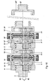
- the second central input shaft - wheel II - is freely rotatably mounted on the central first input shaft I with a bearing.
- the eccentric wheels I.1-I.4 are bearing-mounted at distance 'e' from the centerline of the first shaft I and therefore always rotate at the same speed and direction of rotation as the first shaft I, so at 1,000 rev/min.
- each eccentric wheel directly abuts the stationary tread of the wheel II kept still. If they are toothed, they are even anchored in one another. This ensures that the eccentric wheels need to rotate about their own axes.
- the diameter of wheel II at the location of the tread, is equal to two times the diameter of the eccentric wheels. So, the diameter ratio between the eccentric wheels I.1-I.4. and the concentric wheel II is 1 : 2. The speed at which the eccentric wheels then rotate about their own axes is therefore 2,000 rev/min.
- Fig. 106B shows first input shaft I with eccentric wheels I.1-I.4 and second input shaft II.
- the second input shaft II now rotates as well.
- the direction of rotation of first input shaft I and second input shaft II and the eccentric wheels is indicated with the aid of arrows.
- a second drive now also drives the second input shaft II to the right and suppose this is done at a speed of 1 rev/min.
- the first shaft I continues to rotate at 1,000 rev/min to the right without change. Because the tread of II rotates in the same direction as I, the rotational speed of the eccentric wheels at which they rotate about their own axes will decrease. However, this is not the speed at which they rotate about the central centerline with shaft I; this remains 1,000 rev/min.
- the rotational speed of the eccentric wheels about their own centerline is decelerated, the reduction being equal to 1 rev/min of wheel II because it runs along in the same direction. Because one revolution of wheel II is equal to two revolutions of an eccentric wheel, the own rotation of these wheels is reduced by 2 rev/min, so from 2,000 to 1,998 rev/min. So, the eccentric wheel or assembly of eccentric wheels revolves at 1,000 rev/min with the central first shaft I to the right around the centerline of the transmission, while it further rotates at 1,998 rev/min (also to the right) about its own wheel axis.
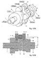
- Fig. 107 represents the first input shaft I with eccentric wheels I.n and the second input shaft II. Further, Fig. 107A further shows a third input shaft III. Fig. 107A shows the configuration in perspective view. Fig. 107B shows the shafts I, II and III and a wheel I.1 in cross section. The above-discussed movements and their results are shown in Fig. 107A where they become manifest.
- arrows A and B indicate opposite directions of rotation of element III.
- the output shaft - element III - indeed simultaneously carries out two completely opposite movements.
- the transmission as shown in Fig. 107B comprises a rotary shaft I, 2 for coupling with a first drive element.
- the rotary shaft I, 2 is provided with a wheel I.1, 4 eccentrically and freely rotatably supported on the shaft I, 2 for coupling with a second drive element.
- the transmission further comprises a ring II, 8 arranged concentrically and rotatably with respect to the rotary shaft I, 2, which ring II, 8 is provided with a first tread 9 cooperating with the tread of the wheel I.1, 4.
- the ring II, 8 is further provided with a second tread 11 cooperating with the tread of an auxiliary drive element - not shown here - such that rotation of the rotary shaft I, 2 results in a corresponding circular revolving movement of the wheel I.1, 4 about the centerline H1 of the rotary shaft I, 2.
- Rotation of the wheel I.1, 4 about its own axis H2 depends on the rotation of the rotary shaft I, 2 and on the rotation of the ring II, 8 about the centerline H1 of the rotary shaft I, 2.
- the wheel I.1, 4 cooperates with a tread 25 of an auxiliary ring 26 arranged concentrically with the rotary shaft I, 2 in a same transmission ratio as with the ring II, 8.
- the auxiliary ring 26 is designed as an end auxiliary ring.
- the ring 26 supports a further rotary shaft III, 27 arranged co-parallel with the rotary shaft.
- Eccentric wheel I.1 eccentric wheel I.2-I.n (fixed condition if more than one eccentric wheel is used)
- the examples show that the rotational speed and the direction of rotation of the output shaft III are the same as the rotational speed and the direction of rotation of input shaft II, independent of the input shaft I.
- the rotating eccentric wheel I.1 'fixes' the output shaft III with respect to the input shaft II.
- the input shaft II which can either stand still, or rotates at a uniform speed, or rotates in an accelerated or decelerated manner, thus controls the movements, including the standstill, of the output shaft III.
- the driving away itself and the acceleration thereof only depend on the available torque.
- a 1,000-fold motor torque is available behind the transmission, neglecting approx. 3% of transmission losses.
- sporty acceleration can take place, but a fuel-efficient, economical acceleration is also possible.
- the transmission control then keeps the motor speed at the lowest position necessary for driving away smoothly.
- the driver can optionally set the VB4D control to economy, sporty or gearshift by pressing a button.
- Economy continuously adjusts the ratio to the tractive resistance and/or emergency stop command.
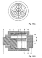
- Fig. 108 relates to a VB4D with internal treads for the shafts II and III.
- Fig. 108A shows a front view
- Fig. 108B shows a cross section.
- Fig. 108C shows a perspective view of the embodiment with internal treads, the shafts I and II having a same direction of rotation.
- the direction of rotation of the shafts I and II is opposite.
- Fig. 109A and Fig. 109B show a front view and a cross section, respectively, of an embodiment with internal treads for the shafts II and III, the eccentricity 'e' being smaller than the diameter of the input shaft I.
- Fig. 109C shows another exemplary embodiment of the VB4D with small eccentricity 'e'. Due to the small eccentricity, the eccentric wheel I.1 needs to be led 'around' the shaft I for being able to continue to carry out its function in the same manner.
- Eccentric wheel I.1 eccentric wheel I.2-I.n (fixed condition if more than one eccentric wheel is used)
- eccentric wheel I.1 rotates oppositely with respect to the rotation of the input shaft I as a result of the internal treads.
- the examples 8-14 also show that, also in these exemplary embodiments, the rotational speed and the direction of rotation of the output shaft III are the same as the rotational speed and direction of rotation of the input shaft II.
- a first function is forming a 'rolling lock' between tread 9 and tread 25, connected by the eccentric wheel I.1 in a ratio of 1 : 1.
- Multiple eccentric wheels can be seen as a cage comprising both surfaces 9 and 25 and fixes them with respect to each other. Then, the 'bars' of the cage are the eccentric wheels (pinions) which can each rotate freely about their own axis.
- the cage is part of I and is driven by the main motor which is connected with I. If nothing else happens now, the main motor cannot exert any force on the output shaft III.
- Fig. 110 illustrates an embodiment in which a 1 : 1 transmission ratio is met, but where the shafts II and III have different diameters at the revolving surfaces with the wheels I.1-I.n.
- the output shaft III then has an elliptic shape.
- the positions of the centerlines of the eccentric wheels I.1-I.n at the location of shaft III differ from the positions of the centerlines at the location of the shaft II.
- the right side of the eccentric wheel is the side of the output shaft III, and the left side of the eccentric wheel is the side of the input shaft II.
- Fig. 110 shows a side elevational view of the left side of the eccentric wheel, the right side in the highest position, the right side in the lowest position, and further a front view with the right side in the highest position and a front view with the right side in the lowest position.
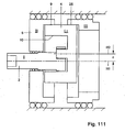
- Fig. 111 shows an exemplary embodiment in which a central opening has been made in output shaft III. This makes the eccentric wheel I.1 accessible for a second output shaft. This second output shaft then moves through the eccentric path with which the wheel I.1 rotates about the centerline H1 of the input shaft I. So, so many eccentric output shafts can be used that there are eccentric wheels, in addition to the central output shaft III. This applies to, for instance, mixing or stirring actions.
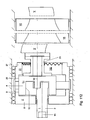
- Fig. 112 shows an exemplary embodiment in which such an eccentric output shaft IV is provided. This variator may also be used as, for instance, a pump. Fig. 112 also shows the starting stub of the pump rotor V, the input of the stator VI, the output of the stator VI and the end stub of the rotor V. VII shows a sealing membrane.
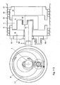
- Fig. 113 also shows a variator with a central opening in output shaft III.
- this embodiment is provided with a replacement of the external servo drive of the second input shaft II.
- I.1 makes more than one revolution around its own axis H2, namely in the ratio of diameter II ö diameter I.1.
- a (servo)motor can compensate for this in order to still obtain a 1 : 1 ratio between II and I.1. Because this is desired as a fixed condition, the (servo)motor with fittings and control may optionally be omitted and be replaced by a less expensive fixed drive from the input shaft I to the second input shaft II.
- the first input shaft I is provided with a toothed ring 100 and the second input shaft with a toothed ring 101. Between the two treads of 100 and 101, there is a freely rotating pinion 102, which is bearing-mounted in a foundation or a housing of the transmission.
- the variety of diameters makes it possible that the above-mentioned compensation can be realized for any pump eccentricity. If, for instance, an eccentric (auxiliary) agitating gear is driven, then the servomotor can be used as a drive of the second input shaft II, so that the agitating gear can rotate at a variable speed with respect to the first shaft I and the output shaft III. Further, the output shaft III itself may, for instance, also be an agitating gear. Also, more than one eccentric (auxiliary) agitating gear may be driven.
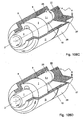
- Fig. 114 shows a transmission with a drive motor of the first input shaft I and an eccentric output shaft IV.
- the rotor movement is not caused by the stator, but is created 'autonomously' from the rotor drive.
- the autonomous rotor movement provides a contactless operation of the rotor within the stator with the result that, with little play with respect to each other, the rotor and the stator form the axially progressively moving cavities in which gas and air are contactlessly - and in a dry-running manner - pumpable.
- Fig. 115 shows a complete pump, provided with a transmission according to the invention.
- the auxiliary provision 103 is a demountable suspension bearing for the rotor for preventing sagging of the rotor.
- a transmission according to the invention can output both a variable and a fixed rotational speed. Further, it is possible to couple more than one output shaft to the transmission. These output shafts move with respect to one another at either a fixed or a variable rotational speed.
Landscapes
- Engineering & Computer Science (AREA)
- General Engineering & Computer Science (AREA)
- Mechanical Engineering (AREA)
- Retarders (AREA)
- Rotary Pumps (AREA)
- Connection Of Motors, Electrical Generators, Mechanical Devices, And The Like (AREA)
- Friction Gearing (AREA)
Abstract
Description
- The invention relates to a transmission for coupling drive elements, in particular a transmission for coupling a first drive element which is a shaft rotating about its centerline and a second drive element which circularly revolves around that centerline with rotation with respect to its own centerline.
-
DE1944562 discloses a transmission, comprising a rotary shaft for coupling with a first drive element, provided with a wheel supported eccentrically and freely rotatably on the shaft for coupling with a second drive element, further comprising a ring arranged concentrically and rotatably with respect to the rotary shaft, which ring is provided with a first tread cooperating with the tread of the wheel such that rotation of the rotary shaft results in a corresponding circular revolving movement of the wheel about the centerline of the rotary shaft, while rotation of the wheel about its own axis depends on the rotation of the rotary shaft, and is therefor regarded as constituting the closest prior art. - Such a transmission is, for instance, used for driving a so-called progressing cavity pump (PC pump), in which a helical rotor revolves rotatingly about its own longitudinal axis around the centerline of a stator in which the rotor is eccentrically received. Per revolving movement around the stator axis, the rotor of the PC pump rotates once in opposite direction about its own axis.
- In order to drive the pump rotor with the aid of an output shaft rotating about its centerline of, for instance, an electric motor, a transmission is needed. In the known PC pumps, this transmission is typically designed as a cardan shaft transmission.
- A drawback of this cardan shaft transmission is that it causes the rotor to exert a relatively large radial force on the stator near the coupled end. Further, a drawback of the known manner of driving is that the rotor is guided with the aid of the stator surface.
- In practice, this causes the PC pump to be subject to relatively strong wear. Further, the stator is designed from relatively elastic material, such as rubber. As a result, in practice, the use of the PC pump has remained limited to pumping thick liquid, such as cement or pastes.
- The invention contemplates a transmission for realizing above-mentioned transmission, with which, while maintaining the advantages, the drawbacks mentioned can be obviated. The invention further contemplates a transmission which can form a variator between two drive elements.
- To this end, the invention provides a transmission, comprising a rotary shaft for coupling with a first drive element, provided with a wheel supported eccentrically and freely rotatably on the shaft for coupling with a second drive element, further comprising a ring arranged concentrically and rotatably with respect to the rotary shaft, which ring is provided with a first tread cooperating which the tread of the wheel and is provided with a second tread cooperating with the tread of an auxiliary drive element, such that rotation of the rotary shaft results in a corresponding circular revolving movement of the wheel around the centerline of the rotary shaft, while rotation of the wheel about its own axis depends on the rotation of the rotary shaft and on the rotation of the ring about the centerline of the rotary shaft.
- By driving the ring with the aid of the auxiliary drive element, the circumference of the inner tread of the ring can, as it were, relatively be increased or decreased, so that the rotation of the wheel can be set as desired. The first and second tread may, for instance, be designed as internal toothings and external toothings of the ring, respectively, but may also be external toothings or internal toothings of different diameters.
- Preferably, the wheel is a toothed wheel and the ring is a toothed ring cooperating with the toothed wheel and a second toothing cooperating with a toothing of the auxiliary drive element. By designing the treads as toothings, an accurate transmission can be realized with a good and efficient force transmission.
- The auxiliary drive element may be coupled with the rotary shaft via a transmission, for instance with a fixed transmission ratio. Such a transmission with fixed transmission ratio may, for instance, be realized with the aid of a toothed wheel transmission between the external toothing of a toothed ring and the rotary shaft. Preferably, one revolution of the rotary shaft results in one opposite revolution of the toothed wheel around its own axis.
- By coupling the auxiliary drive element with a servomotor, for instance by designing the auxiliary drive element as a worm wheel driven via an auxiliary electric motor, which worm wheel engages the external toothing of the toothed ring, the transmission ratio can be chosen freely. In this manner, the transmission can be used as a variator. The wheel may then, for instance, via a cardan shaft transmission, be coupled with an input shaft of a second drive element whose rotary shaft extends co-parallel to the rotary shaft of the first drive element.
- In an elegant manner, in a same transmission ration as with the ring, the wheel cooperates with a tread of a further auxiliary ring arranged next to the ring, concentrically with the rotary shaft. For instance, a toothing of the wheel cooperates with the toothing of the auxiliary ring with the same distance of the line of action to the rotary shaft of the first drive element as the line of action between wheel and ring. Optionally, a same transmission ratio may also be realized with the aid of, for instance, eccentric toothed wheels cooperating with oval toothed wheels.
- Such an auxiliary ring may be designed as an end auxiliary ring supporting a further rotary shaft arranged co-parallel to the rotary shaft and providing the coupling with the second drive element.
- Alternatively, the ring may be designed as an intermediate auxiliary ring provided with a further auxiliary wheel arranged eccentrically and freely rotatably, so that, by repeating the construction, a multi-stage variator can be formed. In such a case, for instance, a second ring arranged concentrically and rotatably with respect to the rotary shaft may be provided, which second ring is provided with an internal tread cooperating with the tread of the auxiliary wheel and is provided with an external tread cooperating with the tread of a second auxiliary drive element.
- If desired, the auxiliary wheel may also cooperate with the internal tread of a second auxiliary ring forming an end auxiliary ring or an auxiliary ring forming, in turn, a second intermediate auxiliary ring for making a third stage, etc.
- By driving the first and second auxiliary drive elements with one or more servomotors, a variator can be created with two control stages. However, the auxiliary drive elements may also be used for realizing branches or inputs with mutually different rotational speeds.
- For bearing-mounting the rotating revolving movement, preferably one or more double bearings are provided which are each built up from a cylindrical first bearing eccentrically received in a second cylindrical bearing.
- In an elegant manner, the bearings are not only designed for absorbing a radial force component, but also for absorbing an axial force component, for instance by designing the bearings as angular ball bearings.
- By sealing the surfaces in which the bearings are located, a bearing shield can be formed.
- Such a double bearing and/or bearing shield may be used in an advantageous manner for bearing-mounting the rotating revolving movement of the wheel or auxiliary wheel, but may, as will be explained hereinbelow, even in itself be used in an advantageous manner in a different environment, for instance for bearing-mounting a helical rotor of a PC pump conventionally driven with a cardan shaft transmission, Oldham coupling or flexible coupling.
- In an advantageous embodiment, the transmission is coupled with a helical rotor so that a PC pump or PC motor can be formed.
- Here, the wheel is preferably coupled with the rotor which is provided with at least one helical winding extending around a rotor centerline which is received in a stator.
- By use of the transmission according to the invention, where the transmission ratio is chosen such that one revolution of the rotary shaft results in one opposite revolution of the wheel around its own axis, the revolution and rotation of the rotor can be driven without exerting radial force on the stator and, further, the rotor does not need to be guided by the stator surface anymore, but it can carry out an independent movement.
- By receiving the free end of the rotor in the above-described double bearing, what can be achieved is that the rotor can be received in the stator opening with accurate fit and, if desired, without contact.
- Rotor and stator may both be manufactured from relatively stiff material, in particular steel. Further, between rotor and stator, an accurate fit may be provided, so that the PC pump can be used as a compressor, or even as a motor.
- In an advantageous manner, the stator has a thin-walled design. Here, on its outer surface, the stator may be provided with ribs extending in axial direction which can act as cooling ribs and/or stiffening ribs.
- By designing the rotor to be thin-walled, what can be achieved is that it can be constructed to be relatively strong and light, while, further, there is a possibility of receiving the rotor in the cooling circuit.
- If desired, the rotor can further be stiffened by receiving an internal profile in the rotor, for instance a helically wound box profile.
- By having the diameter of stator and rotor shift along the centerline, a multi-stage pump or compressor can be formed.
- In this manner, in the direction of movement from the cavity to the rotor/stator combination, one or more capacity shifts can be realized.
- When, at the location of such a shift, a supply channel is provided which opens into the receiving opening, a mixing pump can be realized in an elegant manner.
- When the rotary shaft is an input shaft, the rotor can be a displacement body of a pump, compressor or mixer.
- When the rotary shaft is an output shaft, the rotor can be a displaced body of a motor, for instance a hydraulic motor or an internal combustion engine.
- In an elegant manner, the parts of the sidewalls of the rotor running straight in cross section may further be provided with cavities located below the surface for realizing a resilient seal. Such cavities may, for instance, be filled with a liquid material, allowing a sealing protuberance to be created on the low-pressure side of the stator.
- Such a cavity may, for instance, be formed by receiving a mounting slot in the stator wall, in which a hollow core strip optionally filled with liquid material can be received.
- If desired, the cooperating surfaces of rotor and stator may also be provided with a lining material, such as a chemically resistant material, a wear-resistant and/or friction-reducing material.
- Examples of such lining material are, for instance, PTFE or ceramic material.
- The invention will be explained in more detail on the basis of an exemplary embodiment shown in the drawing, in which:
-
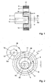
Fig. 1 shows a schematic side elevational view of a first embodiment of a transmission according to the invention; -
Fig. 2 shows a schematic front view of the transmission ofFig. 1 ; -
Fig. 3 shows a schematic top plan view of the transmission ofFig. 1 coupled to a PC pump; -
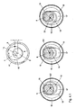
Fig. 4 shows a schematic front view of the stator of the PC pump in which the position of the stator is shown in successive steps with the corresponding positions of the transmission above them; -
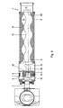
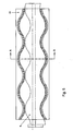
Fig. 5 shows a schematic longitudinal cross section of a thin-walled stator provided with cooling ribs; -
Fig. 5A shows a cross section along the line A-A inFig. 5 ; -
Fig. 6 shows a schematic longitudinal cross section of a rotor-stator combination with shifting diameter; -
Fig. 7 shows a schematic longitudinal cross section of a helical rotor of a PC pump bearing-mounted with an eccentric double bearing; -
Fig. 8 shows a schematic front view of a variant of the transmission with free transmission ratio; -
Fig. 9 shows a schematic side elevational view of the transmission ofFig. 8 ; -
Fig. 10 shows a schematic side elevational view of a multi-stage variant of the transmission; -
Fig. 101 shows an exploded view of an input shaft with an eccentric wheel; -
Fig. 102 shows an exploded view of an input shaft with four eccentric wheels; -
Fig. 103 shows a perspective view of an input shaft with four eccentric wheels; . -
Fig. 104A shows a perspective view of a second input shaft; -
Fig. 104B shows a cross section of a second input shaft; -
Fig. 105A shows a perspective view of a first input shaft, a second input shaft and eccentric wheels; -
Fig. 105B shows a cross section of a first input shaft, a second input shaft and eccentric wheels; -
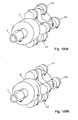
Fig. 106A shows a perspective view of a first input shaft, a second input shaft and eccentric wheels with rotations; -
Fig. 106B shows a perspective view of a first input shaft, a second input shaft and eccentric wheels with rotations, with the second input shaft rotating as well; -
Fig. 106C shows a side elevational view of an assembled wheel; -
Fig. 106D shows a perspective view of a wheel manufactured in one piece; -
Fig. 107A shows a perspective view of a transmission according to the invention; -
Fig. 107B shows a cross section of a transmission according to the invention; -
Fig. 108A shows a front view of a transmission according to the invention with internal treads; -
Fig. 108B shows a cross section of a transmission according to the invention with internal treads; -
Fig. 108C shows a perspective view of a transmission according to the invention with internal treads; -
Fig. 108D shows a perspective view of a transmission according to the invention with internal treads with input shafts rotating oppositely to one another; -
Fig. 109A shows a front view of a transmission according to the invention with internal treads with small eccentricity; -
Fig. 109B shows a cross section of a transmission according to the invention with internal treads with small eccentricity; -
Fig. 109C shows a side elevational view of a transmission according to the invention with internal treads with small eccentricity; -
Fig. 110 shows side elevational views and front views with shifting centerlines of the eccentric wheels; -
Fig. 111 shows a side elevational view of a transmission according to the invention with a central opening in the output shaft; -
Fig. 112 shows a transmission according to the invention with a second output shaft; -
Fig. 113 shows a transmission according to the invention in which a servo drive of the second input shaft is replaced; -
Fig. 114 shows a transmission according to the invention in which the second output shaft is a rotor; -
Fig. 115 shows a transmission according to the invention in a complete pump drive. - It is noted that the Figures are only schematic representations of preferred embodiments of the invention which are given by way of non-limiting exemplary embodiments. In the Figures, same or corresponding parts are designated by same reference numerals.
-
Figs. 1-4 show atransmission 1. Thetransmission 1 comprises arotary shaft 2 arranged rotatably with respect to a centerline H1. The rotary shaft is designed for coupling with afirst drive element 3, for instance an electric motor. Therotary shaft 2 is provided with atoothed wheel 4 supported eccentrically, with eccentricity e, on therotary shaft 2. The toothed wheel is supported on therotary shaft 2 so as to be freely rotatable with respect to its own centerline H2. Thetoothed wheel 4 is designed for coupling with asecond drive element 5, which is, for instance, connected with therotor 6 of aPC pump 7. - The
transmission 1 further comprises atoothed ring 8 arranged concentrically and freely rotatably about the centerline H1 of therotary shaft 2. Thetoothed ring 8 is provided with afirst toothing 9 cooperating with thetoothing 10 of thetoothed wheel 4. - The
toothed ring 8 is further provided with asecond toothing 11 cooperating with thetoothing 12 of an auxiliary drive element 13. - In this exemplary embodiment, the auxiliary drive element is a toothed wheel coupled with the
rotary shaft 2 via a fixed transmission ratio. To this end, the rotary shaft supports atoothed wheel 35 arranged so as to rotate along about centerline H1, which toothedwheel 35 cooperates with atoothed wheel 36 which in turn rotates along with the auxiliary drive element 13 designed as a toothed wheel about an axis of rotation H4. - Here, the transmission ratio between auxiliary drive element 13 and
rotably shaft 2 is such that one revolution of therotary shaft 2 results in an opposite revolution of thetoothed wheel 4 around the centerline H2 of its own shaft. - The
toothed wheel 4 is mounted on aneccentric projection 14 of therotary shaft 2, which is located inside the shaft diameter. Of course, it is also possible to provide a crank projecting with respect to the shaft, on which the toothed wheel can be mounted. - The
rotor 6 of the PC pump is provided with one helical winding 15 extending around a rotor centerline H3. The rotor centerline runs substantially parallel, with eccentric intermediate distance e, with respect to the centerline H1 of therotary shaft 2, which coincides with the centerline of thestator 16. Therotor 6 is received in a receivingopening 17 of thestator 16. The receivingopening 17 is provided with twohelical cavities 18 extending substantially parallel at eccentric distance e with respect to the centerline H1 of therotary shaft 2, which cavities are interconnected via thecenter area 19 of thestator 16. - The pitch of the
helical windings 18 of the stator is two times the pitch of the helical winding 15 of therotor 6. Thus, the number ofhelical windings 18 of thestator 16 is one higher than the number ofhelical windings 15 of therotor 6. - The
rotor 6 and thestator 16 are manufactured from steel or another similar, relatively stiff material. The cooperating surfaces of rotor and stator are provided with a lining, for instance a ceramic coating. - As shown in
Fig. 5 , the stator has a thin-walled design. On its outer surface, thestator 16 is provided withribs 20 extending in axial direction which act as combined cooling and stiffening ribs. - As shown in
Fig. 6 , rotor and stator are provided with a cross section shifting from a smaller diameter D1 to a larger diameter D2, so that the pump comprises two steps. When, at the location of the wider part with diameter D2, a channel which opens into the receivingopening 17 in the stator is provided, this channel can be used for feeding a substance to be mixed to the substrate to be pumped. -
Fig. 3 shows that thePC pump 7 is provided with a cement slurry,input 20 from which cement slurry is suctioned out with the aid of a displacement space moving as a result of therotor 6 moving in the stator receiving opening and is pressed to apress output 21. - One side wall of the
cement slurry input 20 is formed by a bearingshield 30. InFig. 7 , the bearingshield 30 is shown in more detail. The bearing shield bearing-mounts the rotating revolving movement of therotor 6 and thetoothed wheel 4 coupled therewith. The bearing shield is built up from a cylindricalfirst bearing 31 eccentrically received in a secondcylindrical bearing 32. In order to absorb not only a radial force component, but also an axial force component exerted on the rotor by the slurry, thebearings 31 are each designed as double angular ball bearings. In order to prevent passage of slurry, the surfaces in which the bearings are located are sealed. In the embodiment as shown inFig. 7 , the double bearing can be used in an advantageous manner for a progressing cavity apparatus in which a helical rotor revolves rotatingly about its own longitudinal axis around the centerline of a stator in which the rotor is received eccentrically by guiding the side of the rotor which the transmission engages with the aid of an eccentric double bearing. -
Fig. 4 shows how the stator proceeds through the successive steps when making one complete revolution. Here, thestator 16 rotates once in opposite direction about its own centerline H3. In the top representations ofFig. 4 , it is shown that thetoothed ring 8 is rotated to keep the rotation of thetoothed wheel 4 about its centerline H2 limited to one complete rotation. - By using the transmission according to the invention, the rotor can be received in the stator with little play, so that use as a compressor or mud motor, or even internal combustion engine, is possible.
- The free end of the rotor is then preferably bearing-mounted, for instance with the aid of the above-described double eccentric bearing.
- In an elegant manner, the auxiliary drive element 13 can be coupled with a servomotor. In this manner, a variator can be formed. This is schematically shown in
Fig. 8 with the aid of aworm 23 driven by an auxiliary electric motor (not shown) and cooperating with a correspondingworm wheel toothing 11 on the outside of thetoothed ring 8. With the aid of such a construction, the transmission ratio between auxiliary drive element and rotary shaft can be chosen freely so that, per circular revolving movement of the toothed wheel, the corresponding number of rotations of the toothed wheel about its own axis can be set freely. By elegantly providing anaxial continuation 24 of thetoothed wheel 4, the toothed wheel can further be designed for cooperating with atoothing 25 of anauxiliary toothed ring 26 arranged concentrically with therotary shaft 2 with the same transmission ratio as with thetoothed ring 8. Here, theauxiliary toothed ring 26 is designed as an end auxiliary ring. Here, thering 26 supports a furtherrotary shaft 27 providing the coupling with thesecond drive element 5 and arranged co-parallel with the rotary shaft. In this manner, as shown inFig. 9 , a continuously variable transmission can be realized in an elegant manner. - With the aid of such a continuously variable transmission, a completely stepless variable output rotational speed from 0 to the maximum rotational speed can be realized in both directions of rotation. With a rotating input shaft, the output shaft can be stopped without uncoupling being necessary. Very low creeping speeds can be set, so that a lower power of the drive source can be chosen and/or a high torque is available.
- The transmission is 100% slip-free and has a very high efficiency.
- The dimensions are compact, while the construction is relatively simple and comprises few parts.
- Such a variator may, for instance, be used for driving vehicles, hoists, agricultural machines, for propelling ships or for driving tools.
- With the variator, a fixed connection remains present between the input shaft and output shaft at all times. With the aid of the variator, the output shaft of the drive can be stopped. Thus, when it is, for instance, controlled with the aid of an electronic control unit, the variator can excellently be used as a transmission in a car, while, also, functions like ESP or ABS can be realized via the transmission. It is noted that a ring like the auxiliary ring cannot only, as shown here, comprise a ring with inner toothing, but also a ring with outer toothing more closely resembling a wheel.
- In a car or truck, in this manner, wheels can be driven directly via the transmission with an electric motor. In this manner, each wheel can be designed with its own drive motor.
- The transmission can then be received in the rotor kit of the electric motor to thus obtain the most compact possible dimensions.
- With respect to a wheel driven directly with an electric motor controlled with the aid of a frequency control, thus the advantage is achieved that the electric motor can have a relatively light design. This is because, with the aid of the transmission, the torque can be converted for, for instance, accelerating from a standstill. Further, with the aid of the transmission, the rotational speed of the output shaft can be controlled to zero. With the aid of the transmission, the rotating electric motor can be used to retain the output shaft when the output shaft stands still, so that the output shaft is blocked.
- Use of such a wheel directly driven via the transmission with the aid of an electric motor in a vehicle yields numerous advantages. Thus, the conventional shaft sets and differentials can be omitted and batteries or fuel cells can be placed in the space which has become available.
- The center of gravity of the vehicle can be lowered much and due to the different construction of the vehicle, more usable space becomes available. Further, in this manner, a trailer can simply be designed as a trailing device.
-
Fig. 10 shows a schematic side elevational view of a multi-stage variant of the transmission. In this embodiment, a second toothed ring 8' arranged concentrically and rotatably with respect to the rotary shaft is provided. The second toothed ring 8' is provided with an inner toothing 9' cooperating with the toothing 10' of an auxiliary wheel 4'. The second toothed ring 8' is provided with an outer toothing 11' cooperating with the toothing 12' of asecond worm 23 driven by a second servomotor 22' (not shown). - An axial continuation 24' of the auxiliary toothed wheel 4' cooperates with a second auxiliary ring 26'. The second auxiliary ring 26' can form an end auxiliary ring supporting a further
rotary shaft 27 or can, in turn, form a second intermediate auxiliary ring for making a third stage. - By driving the first and
second worms 23, 23' withservomotors 22, 22', a variator can be created with two control stages. However, theworms 23, 23' may also be used for realizing shaft branches with mutually different rotational speeds. - For further elucidation, the invention is again explained in the following with reference to
Figs. 101-115 . - The VanBeek-4D transmission, hereinafter to be referred to as VB4D and/or 4D is a drive reductor for use as:
- a - a continuously variable drive reductor with an endless ratio from 0 (zero) to Overdrive;
- b - a drive reductor with a fixed transmission ratio for ratios from > 0;
- c - a drive reductor with a fixed transmission ratio for driving
- c1 - eccentric helical worm rotors, inter alia also known as worm gear pump;
- Schneckenpumpe and Exzenter-Schneckenpumpe, Progressive Cavity Pump (PCP) and Progressive Cavity Motor (PCM).
- The 4D transmission is based on 3 elementary main parts I, II and III
- I - central first input shaft with minimally one eccentric wheel (I.1-I.n)
- II - central second input servo with at least one centric wheel
- III - use-dependent station (a,b,c) or eccentric (c1) output shaft with at least one wheel
- The wheel treads of the elementary main parts I, II and III may
- d) have any design;
- e) have any position on the respective wheel, while
- f) the movement functions remain unchanged mutually with one another and with respect to one another and jointly
- Wheel Tread examples are: metal tread, plastic, rubber, friction with friction oil, toothed, etc., etc.
- Tread Exemplary embodiment: if toothed, possible toothings are inter alia straight, helical, hypoid, conical toothing, etc. and possible positions for this are on the outer circumference, on the inside, and/or on the side of wheel
- Part I is a central input shaft with at least one eccentric wheel from I.1 to I.n.
-
Fig. 101 shows an input shaft I for one eccentric wheel I.1. -
Fig. 102 shows an input shaft I for four eccentric wheels I.1-I.4. -
Fig. 103 shows an input shaft I with four eccentric wheels I.1-I.4. - Part II is a central second input servo with at least one centric wheel tread.
-
Fig. 104 shows the second input servo shaft as a concentric wheel.Fig. 104A shows part II in perspective view.Fig. 104B shows part II in cross section. -
Fig. 105 shows the assembly with the first input shaft I.Fig. 105A shows parts I and II in perspective view.Fig. 105B shows parts I and II in cross section. The distance between the centerline of eccentric wheel I.1 and the centerline of part I is the eccentricity 'e'. - The second central input shaft - wheel II - is freely rotatably mounted on the central first input shaft I with a bearing.
- In
Fig. 106A , the rotations are made visible which occur when the first input shaft I is driven and the second input shaft II is kept still by the second servomotor. - Suppose that the first input shaft I rotates at 1,000 rev/min.
- The eccentric wheels I.1-I.4 are bearing-mounted at distance 'e' from the centerline of the first shaft I and therefore always rotate at the same speed and direction of rotation as the first shaft I, so at 1,000 rev/min.
- The tread of each eccentric wheel directly abuts the stationary tread of the wheel II kept still. If they are toothed, they are even anchored in one another. This ensures that the eccentric wheels need to rotate about their own axes.
- For the sake of simplicity, we now suppose that the diameter of wheel II, at the location of the tread, is equal to two times the diameter of the eccentric wheels. So, the diameter ratio between the eccentric wheels I.1-I.4. and the concentric wheel II is 1 : 2. The speed at which the eccentric wheels then rotate about their own axes is therefore 2,000 rev/min.
-
Fig. 106B shows first input shaft I with eccentric wheels I.1-I.4 and second input shaft II. The second input shaft II now rotates as well. The direction of rotation of first input shaft I and second input shaft II and the eccentric wheels is indicated with the aid of arrows. A second drive now also drives the second input shaft II to the right and suppose this is done at a speed of 1 rev/min. The first shaft I continues to rotate at 1,000 rev/min to the right without change. Because the tread of II rotates in the same direction as I, the rotational speed of the eccentric wheels at which they rotate about their own axes will decrease. However, this is not the speed at which they rotate about the central centerline with shaft I; this remains 1,000 rev/min. The rotational speed of the eccentric wheels about their own centerline is decelerated, the reduction being equal to 1 rev/min of wheel II because it runs along in the same direction. Because one revolution of wheel II is equal to two revolutions of an eccentric wheel, the own rotation of these wheels is reduced by 2 rev/min, so from 2,000 to 1,998 rev/min. So, the eccentric wheel or assembly of eccentric wheels revolves at 1,000 rev/min with the central first shaft I to the right around the centerline of the transmission, while it further rotates at 1,998 rev/min (also to the right) about its own wheel axis. -
Fig. 107 represents the first input shaft I with eccentric wheels I.n and the second input shaft II. Further,Fig. 107A further shows a third input shaft III.Fig. 107A shows the configuration in perspective view.Fig. 107B shows the shafts I, II and III and a wheel I.1 in cross section. The above-discussed movements and their results are shown inFig. 107A where they become manifest. - At the transmission output, arrows A and B indicate opposite directions of rotation of element III. The output shaft - element III - indeed simultaneously carries out two completely opposite movements. The tread of eccentric wheel I.1 makes the
tread 25 of the output shaft III rotate at 1,998 +ratio 2 = 999 rev/min to the left and that is direction A. At the same time, eccentric wheel I.1 takes thatsame tread 25 along in direction B at the speed of the input shaft I = 1,000 rev/min. So, the resulting speed between A and B is 1 rev/min. Since B is greater than A, the direction of the resultant is in direction B, so to the right. In this manner, a variable transmission is realized with ratios from zero to Overdrive. - The transmission as shown in
Fig. 107B comprises a rotary shaft I, 2 for coupling with a first drive element. The rotary shaft I, 2 is provided with a wheel I.1, 4 eccentrically and freely rotatably supported on the shaft I, 2 for coupling with a second drive element. The transmission further comprises a ring II, 8 arranged concentrically and rotatably with respect to the rotary shaft I, 2, which ring II, 8 is provided with afirst tread 9 cooperating with the tread of the wheel I.1, 4. The ring II, 8 is further provided with asecond tread 11 cooperating with the tread of an auxiliary drive element - not shown here - such that rotation of the rotary shaft I, 2 results in a corresponding circular revolving movement of the wheel I.1, 4 about the centerline H1 of the rotary shaft I, 2. Rotation of the wheel I.1, 4 about its own axis H2 depends on the rotation of the rotary shaft I, 2 and on the rotation of the ring II, 8 about the centerline H1 of the rotary shaft I, 2. Further, the wheel I.1, 4 cooperates with atread 25 of anauxiliary ring 26 arranged concentrically with the rotary shaft I, 2 in a same transmission ratio as with the ring II, 8. Here, theauxiliary ring 26 is designed as an end auxiliary ring. Here, thering 26 supports a further rotary shaft III, 27 arranged co-parallel with the rotary shaft. - Tread diameters: input shaft II = output shaft III (fixed condition)
- Eccentric wheel I.1 = 0.5 x input and output shafts II and III = ratio 2 (no fixed condition, 'accidentally' holds in this example)
- Eccentric wheel I.1 = eccentric wheel I.2-I.n (fixed condition if more than one eccentric wheel is used)
- Left tread diameter of eccentric wheel I.1 = Right tread diameter of eccentric wheel I.1, with identical toothing position.
-
first input shaft I 1,000 rpm to the right second input shaft II 0 rpm third output shaft III ? rpm
n of eccentric wheel I.1 = 1,000 x 2 = 2,000 rpm to the right so that output shaft III 2,000ö 2 = 1,000 rpm to the left = A, but eccentric wheel I.1 also circulates to the right at 1,000 rpm = B - The resultant of A and B = 0 rpm = n of output shaft III
-
first input shaft I 1,000 rpm to the right second input shaft II 0 rpm to the right third output shaft III ? rpm
n of eccentric wheel I.1 = 999 x 2 = 1,998 rpm to the right so that output shaft III 1,998ö 2 = 999 rpm to the left = A, but eccentric wheel I.1 also circulates to the right at 1,000 rpm = B - The resultant of A and B = 1 rpm to the right = n of output shaft III
-
first input shaft I 8,000 rpm to the right second input shaft II 1,200 rpm to the right third output shaft III ? rpm
n of eccentric wheel I.1 = 6,800 x 2 = 13,600 rpm to the right so that output shaft III 13,600ö 2 = 6,800 rpm to the left = A, but eccentric wheel I.1 also circulates to the right at 8,000 rpm = B - The resultant of A and B = 1,200 rpm to the right = n of output shaft III
-
first input shaft I 1,500 rpm to the right second input shaft II 200 rpm to the left third output shaft III ? rpm
n of eccentric wheel I.1 = 999 x 2 = 1,998 rpm to the right so that output shaft III 1,998ö 2 = 999 rpm to the left = A, but eccentric wheel I.1 also circulates to the right at 1,000 rpm = B - The resultant of A and B = 1 rpm to the right = n of output shaft III
-
first input shaft I 1,000 rpm to the right second input shaft II 1 rpm to the right third output shaft III ? rpm
n of eccentric wheel I.1= 999 x 2 = 1,998 rpm to the right so that output shaft III 1,998ö 2 = 999 rpm to the left = A, but eccentric wheel I.1 also circulates to the right at 1,000 rpm = B - The resultant of A and B = 1 rpm to the right = n of output shaft III
-
first input shaft I 1,000 rpm to the right second input shaft II 1 rpm to the right third output shaft III ? rpm
n of eccentric wheel I.1 = 999 x 2 = 1,998 rpm to the right so that output shaft II 1,998ö 2 = 999 rpm to the left = A, but eccentric wheel I.1 also circulates to the right at 1,000 rpm = B
The resultant of A and B = 1 rpm to the right = n of output shaft III -
first input shaft I 1,000 rpm to the right second input shaft II 1 rpm to the right third output shaft III ? rpm
n of eccentric wheel I.1 = 999 x 2 = 1,998 rpm to the right so that output shaft II 1,998ö 2 = 999 rpm to the left = A, but eccentric wheel I.1 also circulates to the right at 1,000 rpm = B - The resultant of A and B = 1 rpm to the right = n of output shaft III
- The examples show that the rotational speed and the direction of rotation of the output shaft III are the same as the rotational speed and the direction of rotation of input shaft II, independent of the input shaft I. One could say that the rotating eccentric wheel I.1 'fixes' the output shaft III with respect to the input shaft II. The input shaft II, which can either stand still, or rotates at a uniform speed, or rotates in an accelerated or decelerated manner, thus controls the movements, including the standstill, of the output shaft III.
- Further properties and/or uses of the transmission are found in starting, driving away and braking.
- The VB4D can be started with the output shaft of the motor being fixedly connected with the VB4D via the input shaft I. With a still servomotor of the input shaft II, the output rotational speed of shaft III is zero. A coupling, either dry or wet, is then not needed anymore.
- When the servomotor stands still, the vehicle is also blocked. This makes a parking brake unnecessary.
- The driving away itself and the acceleration thereof only depend on the available torque. In the high ratios, as with motor revolutions of 1,000 rpm input to 1 rpm output, a 1,000-fold motor torque is available behind the transmission, neglecting approx. 3% of transmission losses. Thus, sporty acceleration can take place, but a fuel-efficient, economical acceleration is also possible. The transmission control then keeps the motor speed at the lowest position necessary for driving away smoothly.
- Similarly to driving away, with the servomotor, it is also possible to reduce speed either forcefully or smoothly to a standstill. Thus, the existing brake provision would not be needed anymore. Technically, not the brake disc and the brake pad are determinative, but the retardation force, the control thereof and the failure analysis and the like. In any case, by use of the VB4D transmission, the use and maintenance of the brakes is reduced.
- In one embodiment, the driver can optionally set the VB4D control to economy, sporty or gearshift by pressing a button. Economy continuously adjusts the ratio to the tractive resistance and/or emergency stop command.
- In the embodiment of
Fig. 107 , the toothings on the left part and right part of an eccentric wheel are aligned. By choosing the operative diameters of the eccentric wheel so as to be equal on the left and right, it is achieved that output shaft III stands still when input shaft II stands still. - Further embodiments are shown in
Fig. 108 andFig. 109 .Fig. 108 relates to a VB4D with internal treads for the shafts II and III.Fig. 108A shows a front view,Fig. 108B shows a cross section.Fig. 108C shows a perspective view of the embodiment with internal treads, the shafts I and II having a same direction of rotation. InFig. 108D , the direction of rotation of the shafts I and II is opposite.Fig. 109A and Fig. 109B show a front view and a cross section, respectively, of an embodiment with internal treads for the shafts II and III, the eccentricity 'e' being smaller than the diameter of the input shaft I.Fig. 109C shows another exemplary embodiment of the VB4D with small eccentricity 'e'. Due to the small eccentricity, the eccentric wheel I.1 needs to be led 'around' the shaft I for being able to continue to carry out its function in the same manner. - Tread diameters: input shaft II = output shaft III (fixed condition)
- Eccentric wheel I.1= 0.5 x input and output shafts II and III = ratio 2 (no fixed condition, 'accidentally' holds in this example)
- Eccentric wheel I.1 = eccentric wheel I.2-I.n (fixed condition if more than one eccentric wheel is used)
- Left tread diameter of eccentric wheel I.1= Right tread diameter of eccentric wheel I.1, with identical toothing position.
-
first input shaft I 1,000 rpm to the right second input shaft II 0 rpm third output shaft III ? rpm
n of eccentric wheel I.1 = 1,000 x 2 = 2,000 rpm to the right so that output shaft III 2,000ö 2 = 1,000 rpm to the left = A, but eccentric wheel I.1 also circulates to the right at 1,000 rpm = B - The resultant of A and B = 0 rpm = n of output shaft III
-
first input shaft I 1,000 rpm to the right second input shaft II 1 rpm to the right third output shaft III ? rpm
n of eccentric wheel I.1 = 999 x 2 = 1,998 rpm to the right so that output shaft III 1,998ö 2 = 999 rpm to the left = A, but eccentric wheel I.1 also circulates to the right at 1,000 rpm = B The resultant of A and B = 1 rpm to the right = n of output shaft III -
first input shaft I 1,000 rpm to the right second input shaft II 1 rpm to the right third output shaft III ? rpm
n of eccentric wheel I.1 = 999 x 2 = 1,998 rpm to the right so that output shaft III 1,998ö 2 = 999 rpm to the left = A, but eccentric wheel I.1 also circulates to the right at 1,000 rpm = B - The resultant of A and B = 1 rpm to the right = n of output shaft III
-
first input shaft I 1,000 rpm to the right second input shaft II 1 rpm to the right third output shaft III ? rpm
n of eccentric wheel I.1 = 999 x 2 = 1,998 rpm to the right so that output shaft II 1,998ö 2 = 999 rpm to the left = A, but eccentric wheel I.1 also circulates to the right at 1,000 rpm = B - The resultant of A and B = 1 rpm to the right = n of output shaft III
- In the exemplary embodiments shown in
Fig. 108 andFig. 109 , eccentric wheel I.1 rotates oppositely with respect to the rotation of the input shaft I as a result of the internal treads. The examples 8-14 also show that, also in these exemplary embodiments, the rotational speed and the direction of rotation of the output shaft III are the same as the rotational speed and direction of rotation of the input shaft II. - An additional advantage of the eccentric wheels can be seen in two functions that the eccentric wheels have.
- A first function is forming a 'rolling lock' between
tread 9 and tread 25, connected by the eccentric wheel I.1 in a ratio of 1 : 1. Multiple eccentric wheels can be seen as a cage comprising bothsurfaces - A second function is that of 'rigid coupling in axial direction' for passing the torque of the main motor on to the shaft III. In order to make this possible, the (servo) drive of input shaft II can be used. The output shaft III starts to rotate along with the input (servo) shaft II and leaves its neutral situation. The total drive power and torque are provided by the main motor if the (servo)motor is fed by the main motor via a power splitter. The total drive power and torque can also be formed from the main motor, for instance a diesel engine, and an extra power source such as for instance one or more electric motors as a (servo) drive of the input shaft II.
-
Fig. 110 illustrates an embodiment in which a 1 : 1 transmission ratio is met, but where the shafts II and III have different diameters at the revolving surfaces with the wheels I.1-I.n. In this exemplary embodiment, the output shaft III then has an elliptic shape. The positions of the centerlines of the eccentric wheels I.1-I.n at the location of shaft III differ from the positions of the centerlines at the location of the shaft II. The right side of the eccentric wheel is the side of the output shaft III, and the left side of the eccentric wheel is the side of the input shaft II.Fig. 110 shows a side elevational view of the left side of the eccentric wheel, the right side in the highest position, the right side in the lowest position, and further a front view with the right side in the highest position and a front view with the right side in the lowest position. -
Fig. 111 shows an exemplary embodiment in which a central opening has been made in output shaft III. This makes the eccentric wheel I.1 accessible for a second output shaft. This second output shaft then moves through the eccentric path with which the wheel I.1 rotates about the centerline H1 of the input shaft I. So, so many eccentric output shafts can be used that there are eccentric wheels, in addition to the central output shaft III. This applies to, for instance, mixing or stirring actions. -
Fig. 112 shows an exemplary embodiment in which such an eccentric output shaft IV is provided. This variator may also be used as, for instance, a pump.Fig. 112 also shows the starting stub of the pump rotor V, the input of the stator VI, the output of the stator VI and the end stub of the rotor V. VII shows a sealing membrane. -
Fig. 113 also shows a variator with a central opening in output shaft III. However, this embodiment is provided with a replacement of the external servo drive of the second input shaft II. With one revolution of I, I.1 makes more than one revolution around its own axis H2, namely in the ratio of diameter II ö diameter I.1. In order to also obtain one rotation of a wheel I.1 for one revolution of the rotor I, a (servo)motor can compensate for this in order to still obtain a 1 : 1 ratio between II and I.1. Because this is desired as a fixed condition, the (servo)motor with fittings and control may optionally be omitted and be replaced by a less expensive fixed drive from the input shaft I to the second input shaft II. To this end, the first input shaft I is provided with atoothed ring 100 and the second input shaft with atoothed ring 101. Between the two treads of 100 and 101, there is a freely rotatingpinion 102, which is bearing-mounted in a foundation or a housing of the transmission. The variety of diameters makes it possible that the above-mentioned compensation can be realized for any pump eccentricity. If, for instance, an eccentric (auxiliary) agitating gear is driven, then the servomotor can be used as a drive of the second input shaft II, so that the agitating gear can rotate at a variable speed with respect to the first shaft I and the output shaft III. Further, the output shaft III itself may, for instance, also be an agitating gear. Also, more than one eccentric (auxiliary) agitating gear may be driven. -
Fig. 114 shows a transmission with a drive motor of the first input shaft I and an eccentric output shaft IV. By designing the rotor as in the exemplary embodiment ofFig. 114 , the rotor movement is not caused by the stator, but is created 'autonomously' from the rotor drive. The autonomous rotor movement provides a contactless operation of the rotor within the stator with the result that, with little play with respect to each other, the rotor and the stator form the axially progressively moving cavities in which gas and air are contactlessly - and in a dry-running manner - pumpable. -
Fig. 115 shows a complete pump, provided with a transmission according to the invention. Theauxiliary provision 103 is a demountable suspension bearing for the rotor for preventing sagging of the rotor. - A transmission according to the invention can output both a variable and a fixed rotational speed. Further, it is possible to couple more than one output shaft to the transmission. These output shafts move with respect to one another at either a fixed or a variable rotational speed.
- It will be clear that the invention is not limited to the exemplary embodiments shown herein, but that many variations are possible within the scope of the invention as described in the following claims.
Claims (29)
- A transmission, comprising a rotary shaft for coupling with a first drive element, provided with a wheel supported eccentrically and freely rotatably on the shaft for coupling with a second drive element, further comprising a ring arranged concentrically and rotatably with respect to the rotary shaft, which ring is provided with a first tread cooperating with the tread of the wheel and a second tread cooperating with the tread of an auxiliary drive element, such that rotation of the rotary shaft results in a corresponding circular revolving movement of the wheel about the centerline of the rotary shaft, while rotation of the wheel about its own axis depends on the rotation of the rotary shaft and on the rotation of the ring about the centerline of the rotary shaft.
- A transmission according to the preceding claim, wherein the wheel further cooperates with a tread of an auxiliary ring arranged concentrically with the rotary shaft in a same transmission ratio as with the ring.
- A transmission according to claim 2, wherein ring and auxiliary ring are arranged in an axially spaced manner.
- A transmission according to any one of claims 1-3, wherein the wheel is coupled with the second drive element via an axial continuation.
- A transmission according to claim 4, wherein the rotary shaft of the second drive element is coaxial with the rotary shaft of the wheel.
- A transmission according to any one of claims 1-5, wherein an auxiliary ring designed as an end auxiliary ring is provided which supports a further rotary shaft arranged co-parallel with the rotably shaft, which provides the coupling with the second drive element.
- A transmission according to any one of claims 1-5, wherein the auxiliary ring is designed as an intermediate auxiliary ring which is provided with a further wheel arranged eccentrically and freely rotatably.
- A transmission according to any one of claims 1-7, wherein the wheel is a, toothed wheel and wherein the ring is a toothed ring with a first toothing cooperating with the toothed wheel and with a second toothing cooperating with a toothing of the auxiliary drive element.
- A transmission according to any one of claims 1-8, wherein the auxiliary drive element is coupled with the rotary shaft via a transmission.
- A transmission according to any one of claims 1-8, wherein the auxiliary drive element is coupled with the rotary shaft with a fixed transmission ratio.
- A transmission according to claim 10, wherein the transmission ratio between auxiliary drive element and rotary shaft is such that one revolution of the rotary shaft results in one revolution of the wheel around its own axis.
- A transmission according to any one of claims 1-11, wherein the auxiliary drive element is coupled with a servomotor.
- A transmission according to any one of claims 1-12, wherein, for bearing-mounting the rotating revolving movement, one or more double eccentric bearings are provided which are each built up from a cylindrical first bearing eccentrically received in a cylindrical second bearing.
- A transmission according to claim 13, wherein, at least with one double eccentric bearing, the surfaces in which the bearings are located are sealed so that a bearing shield is formed.
- A transmission according to any one of the preceding claims, wherein the wheel is coupled with a rotor which is provided with at least one helical winding extending around a rotor centerline.
- A transmission according to claim 15, wherein the rotor centerline is arranged running substantially parallel, eccentrically with respect to the centerline of the rotary shaft.
- A transmission according to claim 16., wherein the rotor is received in a receiving opening of a stator, which receiving opening is provided with at least two helical windings extending substantially parallel, eccentric with respect to the centerline of the rotary shaft, which windings are interconnected via the center area of the stator.
- A transmission according to claim 17, wherein the pitch of the helical windings of the stator is two times the pitch of the helical windings of the rotor, and wherein the number of helical windings of the stator is one higher than that of the rotor.
- A transmission according to any one of claims 15-18, wherein rotor and stator are manufactured from relatively stiff material, in particular from steel.
- A transmission according to any one of claims 5-19, wherein rotor and/or stator is provided with a lining.
- A transmission according to any one of claims 15-20, wherein the stator has a thin-walled design.
- A transmission according to claim 21, wherein, on its outer surface, the stator is provided with ribs extending in axial direction.
- A transmission according to any one of claims 15-22, wherein the diameters of stator and rotor shift along the centerline.
- A transmission according to claim 23, wherein, at the location of the shift, the stator is provided with a channel opening up into the receiving opening.
- A transmission according to any one of claims 15-24, wherein the rotor has a hollow design.
- A transmission according to any one of claims 15-25, wherein the rotary shaft is an input shaft and the rotor is a displacement body of a pump, compressor or mixer.
- A transmission according to any one of claims 15-25, wherein the rotary shaft is an output shaft and wherein the rotor is a displaced body of a motor.
- A transmission according to any one of claims 15-27, wherein the end of the rotor coupled with the toothed wheel is received in a double eccentric bearing according to claim 13 or 14.
- A transmission according to any one of claims 15-28, wherein the free end of the rotor is bearing-mounted in a double eccentric bearing according to claim 13 or 14.
Applications Claiming Priority (2)
| Application Number | Priority Date | Filing Date | Title |
|---|---|---|---|
| NL1029087A NL1029087C2 (en) | 2005-05-20 | 2005-05-20 | Transmission VanBeek-4D. |
| PCT/NL2006/000254 WO2006123927A1 (en) | 2005-05-20 | 2006-05-19 | Transmission with orbital gears |
Publications (2)
| Publication Number | Publication Date |
|---|---|
| EP1888943A1 EP1888943A1 (en) | 2008-02-20 |
| EP1888943B1 true EP1888943B1 (en) | 2010-02-17 |
Family
ID=35527927
Family Applications (1)
| Application Number | Title | Priority Date | Filing Date |
|---|---|---|---|
| EP06747549A Not-in-force EP1888943B1 (en) | 2005-05-20 | 2006-05-19 | Transmission with orbital gears |
Country Status (7)
| Country | Link |
|---|---|
| EP (1) | EP1888943B1 (en) |
| KR (1) | KR101280143B1 (en) |
| CN (1) | CN101283199B (en) |
| AT (1) | ATE458155T1 (en) |
| DE (1) | DE602006012311D1 (en) |
| NL (1) | NL1029087C2 (en) |
| WO (1) | WO2006123927A1 (en) |
Cited By (1)
| Publication number | Priority date | Publication date | Assignee | Title |
|---|---|---|---|---|
| WO2022122858A1 (en) * | 2020-12-09 | 2022-06-16 | Volkswagen Aktiengesellschaft | Pump device for a hydraulic system of a motor vehicle, hydraulic system |
Families Citing this family (13)
| Publication number | Priority date | Publication date | Assignee | Title |
|---|---|---|---|---|
| NL2002905C2 (en) * | 2009-05-19 | 2010-11-22 | Mantel Maria | IMPROVED TRANSMISSION. |
| US8083508B2 (en) * | 2010-01-15 | 2011-12-27 | Blue Helix, Llc | Progressive cavity compressor having check valves on the discharge endplate |
| GB201019614D0 (en) * | 2010-11-19 | 2010-12-29 | Eatec Ltd | Apparatus and method for controlling or limiting rotor orbit in moving cavity motors and pumps |
| US9482223B2 (en) | 2010-11-19 | 2016-11-01 | Smith International, Inc. | Apparatus and method for controlling or limiting rotor orbit in moving cavity motors and pumps |
| CN103946478B (en) | 2011-11-18 | 2017-03-15 | 史密斯国际有限公司 | Positive displacement motor with radially constrained rotor clips |
| CA2880270A1 (en) * | 2012-08-03 | 2014-02-06 | James F. Kuhn | Coupling and mud motor transmission |
| JP6188015B2 (en) | 2013-05-21 | 2017-08-30 | 兵神装備株式会社 | Uniaxial eccentric screw pump |
| KR101959269B1 (en) * | 2015-05-20 | 2019-03-18 | 사우쓰 차이나 유니버시티 오브 테크놀로지 | And apparatus for coaxially outputting rotation and revolution |
| CN108869293A (en) * | 2017-09-26 | 2018-11-23 | 江西三友压缩机有限公司 | Three chamber cam compressors of one kind and gas compression method |
| CA3119835A1 (en) | 2018-11-13 | 2020-05-22 | Rubicon Oilfield International, Inc. | Three axis vibrating device |
| DE102021205936A1 (en) * | 2021-06-11 | 2022-12-15 | Putzmeister Engineering Gmbh | Eccentric screw pump device, pump system, discharge system and use of an eccentric screw pump device and/or a pump system and/or a discharge system |
| CN114151514B (en) * | 2021-12-03 | 2023-07-21 | 广东博智林机器人有限公司 | Eccentric speed reducer and screw pump |
| CN114526234B (en) * | 2022-01-07 | 2023-12-15 | 安徽泰臻真空科技有限公司 | Air extractor for spherical tokamak device |
Family Cites Families (7)
| Publication number | Priority date | Publication date | Assignee | Title |
|---|---|---|---|---|
| GB272206A (en) * | 1926-06-04 | 1927-10-20 | Josef Groebl | Improvements in or relating to variable gears |
| DE1944562A1 (en) * | 1969-09-02 | 1971-03-11 | Seidl Wilhelm Dipl Ing | Special drive for a displacement screw pump |
| US4080115A (en) * | 1976-09-27 | 1978-03-21 | A-Z International Tool Company | Progressive cavity drive train |
| US4170441A (en) * | 1977-10-21 | 1979-10-09 | Smith International, Inc. | Speed changer for in-hole motors |
| FR2609754A1 (en) * | 1987-01-21 | 1988-07-22 | Nicolas Yves | MULTIFUNCTION SCREW MOTOR WITHOUT CARDAN SEAL |
| EP0329741B1 (en) * | 1987-09-09 | 1992-12-16 | FREY, Heinz | Continuously adjustable drive |
| FR2775043B1 (en) * | 1998-02-16 | 2000-04-14 | Tien Phu Le | DRIVE DEVICE AND USE OF SUCH A DEVICE IN A METHOD OF REDUCING OR CONTROLLING ROTATION SPEED |
-
2005
- 2005-05-20 NL NL1029087A patent/NL1029087C2/en not_active IP Right Cessation
-
2006
- 2006-05-19 WO PCT/NL2006/000254 patent/WO2006123927A1/en not_active Ceased
- 2006-05-19 EP EP06747549A patent/EP1888943B1/en not_active Not-in-force
- 2006-05-19 KR KR1020077029790A patent/KR101280143B1/en not_active Expired - Fee Related
- 2006-05-19 CN CN2006800261151A patent/CN101283199B/en not_active Expired - Fee Related
- 2006-05-19 DE DE602006012311T patent/DE602006012311D1/en active Active
- 2006-05-19 AT AT06747549T patent/ATE458155T1/en not_active IP Right Cessation
Cited By (1)
| Publication number | Priority date | Publication date | Assignee | Title |
|---|---|---|---|---|
| WO2022122858A1 (en) * | 2020-12-09 | 2022-06-16 | Volkswagen Aktiengesellschaft | Pump device for a hydraulic system of a motor vehicle, hydraulic system |
Also Published As
| Publication number | Publication date |
|---|---|
| KR101280143B1 (en) | 2013-07-01 |
| CN101283199A (en) | 2008-10-08 |
| NL1029087C2 (en) | 2006-11-21 |
| EP1888943A1 (en) | 2008-02-20 |
| KR20080065911A (en) | 2008-07-15 |
| CN101283199B (en) | 2011-04-13 |
| WO2006123927A1 (en) | 2006-11-23 |
| ATE458155T1 (en) | 2010-03-15 |
| DE602006012311D1 (en) | 2010-04-01 |
Similar Documents
| Publication | Publication Date | Title |
|---|---|---|
| EP1888943B1 (en) | Transmission with orbital gears | |
| US8430779B2 (en) | Power-dividing gear train assembly for motor vehicles | |
| JP2003532029A (en) | Internal planetary gear transmission | |
| EP2433030B1 (en) | Transmission | |
| CN220059900U (en) | Variable speed crankshaft and compressor | |
| US20080107550A1 (en) | Eletric pump | |
| US5059163A (en) | Trans-planetary mechanical torque impeller | |
| KR100967506B1 (en) | Geared motor | |
| CN209569311U (en) | A kind of raceway oscillating tooth torque aggrandizement apparatus | |
| CN115789200A (en) | Bevel gear planetary gear differential speed reducer and device using same | |
| CN109780141B (en) | Conjugate cam hypocycloid speed reducer | |
| CN102338207A (en) | Case of transmission | |
| CN1074515C (en) | Optional tooth number complex conjugate tooth pin-wheel gearing device | |
| CN219452788U (en) | Novel chassis transmission system reduction gearbox | |
| WO2022132489A1 (en) | Nutational cycloidal reducer | |
| CN222798089U (en) | Deflection speed reducer | |
| CN222415877U (en) | Gear box with coaxial double-speed-ratio output | |
| CN219865862U (en) | Compressor crankshaft, compressor and air conditioner | |
| CN220577348U (en) | Steering gear and vehicle | |
| CN221332736U (en) | Model car and miniature remote control trailer | |
| CN217207648U (en) | Fixed gear ring step inner speed changing planetary reducer | |
| CN223590923U (en) | A mid-mounted motor and electric bicycle | |
| EP4518110A2 (en) | Motor assembly | |
| CN221547091U (en) | Crane with transfer box | |
| WO1992002745A1 (en) | Motion transmitting devices |
Legal Events
| Date | Code | Title | Description |
|---|---|---|---|
| PUAI | Public reference made under article 153(3) epc to a published international application that has entered the european phase |
Free format text: ORIGINAL CODE: 0009012 |
|
| 17P | Request for examination filed |
Effective date: 20071219 |
|
| AK | Designated contracting states |
Kind code of ref document: A1 Designated state(s): AT BE BG CH CY CZ DE DK EE ES FI FR GB GR HU IE IS IT LI LT LU LV MC NL PL PT RO SE SI SK TR |
|
| DAX | Request for extension of the european patent (deleted) | ||
| GRAP | Despatch of communication of intention to grant a patent |
Free format text: ORIGINAL CODE: EPIDOSNIGR1 |
|
| GRAS | Grant fee paid |
Free format text: ORIGINAL CODE: EPIDOSNIGR3 |
|
| RIN1 | Information on inventor provided before grant (corrected) |
Inventor name: VAN BEEK, PIETER, ERICH |
|
| GRAA | (expected) grant |
Free format text: ORIGINAL CODE: 0009210 |
|
| AK | Designated contracting states |
Kind code of ref document: B1 Designated state(s): AT BE BG CH CY CZ DE DK EE ES FI FR GB GR HU IE IS IT LI LT LU LV MC NL PL PT RO SE SI SK TR |
|
| REG | Reference to a national code |
Ref country code: GB Ref legal event code: FG4D |
|
| REG | Reference to a national code |
Ref country code: CH Ref legal event code: EP |
|
| REG | Reference to a national code |
Ref country code: IE Ref legal event code: FG4D |
|
| REF | Corresponds to: |
Ref document number: 602006012311 Country of ref document: DE Date of ref document: 20100401 Kind code of ref document: P |
|
| REG | Reference to a national code |
Ref country code: NL Ref legal event code: VDEP Effective date: 20100217 |
|
| LTIE | Lt: invalidation of european patent or patent extension |
Effective date: 20100217 |
|
| PG25 | Lapsed in a contracting state [announced via postgrant information from national office to epo] |
Ref country code: LT Free format text: LAPSE BECAUSE OF FAILURE TO SUBMIT A TRANSLATION OF THE DESCRIPTION OR TO PAY THE FEE WITHIN THE PRESCRIBED TIME-LIMIT Effective date: 20100217 Ref country code: ES Free format text: LAPSE BECAUSE OF FAILURE TO SUBMIT A TRANSLATION OF THE DESCRIPTION OR TO PAY THE FEE WITHIN THE PRESCRIBED TIME-LIMIT Effective date: 20100528 Ref country code: PT Free format text: LAPSE BECAUSE OF FAILURE TO SUBMIT A TRANSLATION OF THE DESCRIPTION OR TO PAY THE FEE WITHIN THE PRESCRIBED TIME-LIMIT Effective date: 20100617 Ref country code: IS Free format text: LAPSE BECAUSE OF FAILURE TO SUBMIT A TRANSLATION OF THE DESCRIPTION OR TO PAY THE FEE WITHIN THE PRESCRIBED TIME-LIMIT Effective date: 20100617 |
|
| PG25 | Lapsed in a contracting state [announced via postgrant information from national office to epo] |
Ref country code: LV Free format text: LAPSE BECAUSE OF FAILURE TO SUBMIT A TRANSLATION OF THE DESCRIPTION OR TO PAY THE FEE WITHIN THE PRESCRIBED TIME-LIMIT Effective date: 20100217 Ref country code: FI Free format text: LAPSE BECAUSE OF FAILURE TO SUBMIT A TRANSLATION OF THE DESCRIPTION OR TO PAY THE FEE WITHIN THE PRESCRIBED TIME-LIMIT Effective date: 20100217 Ref country code: PL Free format text: LAPSE BECAUSE OF FAILURE TO SUBMIT A TRANSLATION OF THE DESCRIPTION OR TO PAY THE FEE WITHIN THE PRESCRIBED TIME-LIMIT Effective date: 20100217 Ref country code: SI Free format text: LAPSE BECAUSE OF FAILURE TO SUBMIT A TRANSLATION OF THE DESCRIPTION OR TO PAY THE FEE WITHIN THE PRESCRIBED TIME-LIMIT Effective date: 20100217 Ref country code: AT Free format text: LAPSE BECAUSE OF FAILURE TO SUBMIT A TRANSLATION OF THE DESCRIPTION OR TO PAY THE FEE WITHIN THE PRESCRIBED TIME-LIMIT Effective date: 20100217 |
|
| PG25 | Lapsed in a contracting state [announced via postgrant information from national office to epo] |
Ref country code: BE Free format text: LAPSE BECAUSE OF FAILURE TO SUBMIT A TRANSLATION OF THE DESCRIPTION OR TO PAY THE FEE WITHIN THE PRESCRIBED TIME-LIMIT Effective date: 20100217 Ref country code: SE Free format text: LAPSE BECAUSE OF FAILURE TO SUBMIT A TRANSLATION OF THE DESCRIPTION OR TO PAY THE FEE WITHIN THE PRESCRIBED TIME-LIMIT Effective date: 20100217 Ref country code: RO Free format text: LAPSE BECAUSE OF FAILURE TO SUBMIT A TRANSLATION OF THE DESCRIPTION OR TO PAY THE FEE WITHIN THE PRESCRIBED TIME-LIMIT Effective date: 20100217 Ref country code: NL Free format text: LAPSE BECAUSE OF FAILURE TO SUBMIT A TRANSLATION OF THE DESCRIPTION OR TO PAY THE FEE WITHIN THE PRESCRIBED TIME-LIMIT Effective date: 20100217 Ref country code: GR Free format text: LAPSE BECAUSE OF FAILURE TO SUBMIT A TRANSLATION OF THE DESCRIPTION OR TO PAY THE FEE WITHIN THE PRESCRIBED TIME-LIMIT Effective date: 20100518 Ref country code: EE Free format text: LAPSE BECAUSE OF FAILURE TO SUBMIT A TRANSLATION OF THE DESCRIPTION OR TO PAY THE FEE WITHIN THE PRESCRIBED TIME-LIMIT Effective date: 20100217 Ref country code: CY Free format text: LAPSE BECAUSE OF FAILURE TO SUBMIT A TRANSLATION OF THE DESCRIPTION OR TO PAY THE FEE WITHIN THE PRESCRIBED TIME-LIMIT Effective date: 20100217 |
|
| PG25 | Lapsed in a contracting state [announced via postgrant information from national office to epo] |
Ref country code: BG Free format text: LAPSE BECAUSE OF FAILURE TO SUBMIT A TRANSLATION OF THE DESCRIPTION OR TO PAY THE FEE WITHIN THE PRESCRIBED TIME-LIMIT Effective date: 20100517 Ref country code: CZ Free format text: LAPSE BECAUSE OF FAILURE TO SUBMIT A TRANSLATION OF THE DESCRIPTION OR TO PAY THE FEE WITHIN THE PRESCRIBED TIME-LIMIT Effective date: 20100217 Ref country code: SK Free format text: LAPSE BECAUSE OF FAILURE TO SUBMIT A TRANSLATION OF THE DESCRIPTION OR TO PAY THE FEE WITHIN THE PRESCRIBED TIME-LIMIT Effective date: 20100217 |
|
| PLBE | No opposition filed within time limit |
Free format text: ORIGINAL CODE: 0009261 |
|
| STAA | Information on the status of an ep patent application or granted ep patent |
Free format text: STATUS: NO OPPOSITION FILED WITHIN TIME LIMIT |
|
| PG25 | Lapsed in a contracting state [announced via postgrant information from national office to epo] |
Ref country code: MC Free format text: LAPSE BECAUSE OF NON-PAYMENT OF DUE FEES Effective date: 20100531 |
|
| REG | Reference to a national code |
Ref country code: CH Ref legal event code: PL |
|
| 26N | No opposition filed |
Effective date: 20101118 |
|
| GBPC | Gb: european patent ceased through non-payment of renewal fee |
Effective date: 20100519 |
|
| PG25 | Lapsed in a contracting state [announced via postgrant information from national office to epo] |
Ref country code: DK Free format text: LAPSE BECAUSE OF FAILURE TO SUBMIT A TRANSLATION OF THE DESCRIPTION OR TO PAY THE FEE WITHIN THE PRESCRIBED TIME-LIMIT Effective date: 20100217 |
|
| PG25 | Lapsed in a contracting state [announced via postgrant information from national office to epo] |
Ref country code: LI Free format text: LAPSE BECAUSE OF NON-PAYMENT OF DUE FEES Effective date: 20100531 Ref country code: CH Free format text: LAPSE BECAUSE OF NON-PAYMENT OF DUE FEES Effective date: 20100531 |
|
| PG25 | Lapsed in a contracting state [announced via postgrant information from national office to epo] |
Ref country code: IT Free format text: LAPSE BECAUSE OF FAILURE TO SUBMIT A TRANSLATION OF THE DESCRIPTION OR TO PAY THE FEE WITHIN THE PRESCRIBED TIME-LIMIT Effective date: 20100217 |
|
| PG25 | Lapsed in a contracting state [announced via postgrant information from national office to epo] |
Ref country code: IE Free format text: LAPSE BECAUSE OF NON-PAYMENT OF DUE FEES Effective date: 20100519 |
|
| PG25 | Lapsed in a contracting state [announced via postgrant information from national office to epo] |
Ref country code: GB Free format text: LAPSE BECAUSE OF NON-PAYMENT OF DUE FEES Effective date: 20100519 |
|
| PG25 | Lapsed in a contracting state [announced via postgrant information from national office to epo] |
Ref country code: LU Free format text: LAPSE BECAUSE OF NON-PAYMENT OF DUE FEES Effective date: 20100519 Ref country code: HU Free format text: LAPSE BECAUSE OF FAILURE TO SUBMIT A TRANSLATION OF THE DESCRIPTION OR TO PAY THE FEE WITHIN THE PRESCRIBED TIME-LIMIT Effective date: 20100818 |
|
| PG25 | Lapsed in a contracting state [announced via postgrant information from national office to epo] |
Ref country code: TR Free format text: LAPSE BECAUSE OF FAILURE TO SUBMIT A TRANSLATION OF THE DESCRIPTION OR TO PAY THE FEE WITHIN THE PRESCRIBED TIME-LIMIT Effective date: 20100217 |
|
| REG | Reference to a national code |
Ref country code: FR Ref legal event code: PLFP Year of fee payment: 10 |
|
| REG | Reference to a national code |
Ref country code: FR Ref legal event code: PLFP Year of fee payment: 11 |
|
| PGFP | Annual fee paid to national office [announced via postgrant information from national office to epo] |
Ref country code: DE Payment date: 20160520 Year of fee payment: 11 |
|
| PGFP | Annual fee paid to national office [announced via postgrant information from national office to epo] |
Ref country code: FR Payment date: 20160520 Year of fee payment: 11 |
|
| REG | Reference to a national code |
Ref country code: DE Ref legal event code: R119 Ref document number: 602006012311 Country of ref document: DE |
|
| REG | Reference to a national code |
Ref country code: FR Ref legal event code: ST Effective date: 20180131 |
|
| PG25 | Lapsed in a contracting state [announced via postgrant information from national office to epo] |
Ref country code: DE Free format text: LAPSE BECAUSE OF NON-PAYMENT OF DUE FEES Effective date: 20171201 |
|
| PG25 | Lapsed in a contracting state [announced via postgrant information from national office to epo] |
Ref country code: FR Free format text: LAPSE BECAUSE OF NON-PAYMENT OF DUE FEES Effective date: 20170531 |