EP1888872B1 - Pipe-handling apparatus - Google Patents
Pipe-handling apparatus Download PDFInfo
- Publication number
- EP1888872B1 EP1888872B1 EP06752742.4A EP06752742A EP1888872B1 EP 1888872 B1 EP1888872 B1 EP 1888872B1 EP 06752742 A EP06752742 A EP 06752742A EP 1888872 B1 EP1888872 B1 EP 1888872B1
- Authority
- EP
- European Patent Office
- Prior art keywords
- pipe
- carrier
- ramp
- handling apparatus
- cable
- Prior art date
- Legal status (The legal status is an assumption and is not a legal conclusion. Google has not performed a legal analysis and makes no representation as to the accuracy of the status listed.)
- Expired - Fee Related
Links
Images


Classifications
-
- E—FIXED CONSTRUCTIONS
- E21—EARTH DRILLING; MINING
- E21B—EARTH DRILLING, e.g. DEEP DRILLING; OBTAINING OIL, GAS, WATER, SOLUBLE OR MELTABLE MATERIALS OR A SLURRY OF MINERALS FROM WELLS
- E21B19/00—Handling rods, casings, tubes or the like outside the borehole, e.g. in the derrick; Apparatus for feeding the rods or cables
- E21B19/14—Racks, ramps, troughs or bins, for holding the lengths of rod singly or connected; Handling between storage place and borehole
- E21B19/15—Racking of rods in horizontal position; Handling between horizontal and vertical position
- E21B19/155—Handling between horizontal and vertical position
Description
- The present invention relates to a pipe-handling apparatus for use in oil well operations.
- During borehole-forming and completion operations, it is necessary to make up and/or break down long strings of tubular goods such as drill pipe and casing. The string of pipe may be thousands of Meters long, and it is therefore necessary to transport pipe joints (approximately 10 to 14 Meters in length) from a pipe rack located away from the rig up to the rig floor. When being tripped out of the hole, the string of pipe is broken down into separate joints and returned to the pipe rack.
- The handling of oilwell pipe is one of the most dangerous jobs on a drilling rig. Some of the pipe joints weigh thousands of pounds, and it is difficult to move the pipe from a horizontal position below and away from the rig into a vertical position overlying hole center in the rig.
- Pipe handling apparatus are known from
US 4103898 andCA2496440 - It would be desirable to have made available a pipe-handling apparatus that is useful for transporting pipe between the pipe rack and the rig floor with little danger of the pipe or the pipe racking apparatus falling and injuring property and personnel. It would, alternately or in addition, be desirable if the apparatus could position the pipe at an inclined location with an end, for example the box end, of the pipe overhanging the rig floor in ready access to the elevators. Alternately or in addition, it would also be desirable to provide a pipe-handling apparatus that reduces the requirements for manual handling. Such an apparatus is the subject of the present invention.
- In accordance with a broad aspect of the present invention, there is provided a pipe- handling apparatus for moving a pipe to and from a drilling floor of a drilling rig, the pipe handling apparatus comprising: a main support structure, a ramp extendable between the main support structure and the drilling floor, a fixed-length pipe carrier (22) mounted on the main support structure for moving relative thereto between a lower position and an elevated position over the ramp, the carrier including a ramp end adjacent the ramp, an opposite end, and an elongate indentation on its upper surface to accommodate a pipe therein, a lift arm including a first end and a second end, the lift arm being pivotally connected at its first end adjacent the opposite end of the carrier and operable below the carrier to lift and support the carrier's opposite end to an elevated position, a track on the main support structure for supporting axial sliding motion of the carrier and the lift arm therealong, the track including a stop for limiting axial movement of the second end of the lift arm along the track toward the ramp, and a drive system for pulling the carrier from the lower position to ride along the ramp to an elevated position, the drive system adapted to pull the lift arm along the track until it is stopped against the stop in the track and to continue pulling to cause the lift arm to be pivoted about the stop to lift the carrier into the elevated position, characterized in that: the drive system includes a cable-drive which includes a winch and a cable connected between the carrier and the winch, the cable arranged to pull the carrier up along the ramp; the ramp is configured to accept and support the ramp end of the carrier as the ramp end of the carrier moves over the ramp; and the ramp includes a bearing surface on its upper end capable of supporting movement of the carrier thereover; and the pipe carrier and the drive system are selected to permit the pipe carrier to ride up and extend past the end of the ramp over the drilling floor such that the ramp end of the fixed-length pipe carrier is extended past the upper end of the ramp and over the drilling floor when in the elevated position.
- It is to be understood that other aspects of the present invention will become readily apparent to those skilled in the art from the following detailed description, wherein various embodiments of the invention are shown and described by way of illustration. As will be realized, the invention is capable for other and different embodiments and its several details are capable of modification in various other respects, all without departing from the scope of the appended claims. Accordingly the drawings and detailed description are to be regarded as illustrative in nature and not as restrictive.
- Referring to the drawings wherein like reference numerals indicate similar parts throughout the several views, several aspects of the present invention are illustrated by way of example, and not by way of limitation, in detail in the figures, wherein:
-
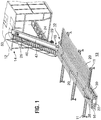
Figure 1 is a perspective view of a pipe-handling apparatus, made in accordance with the present invention, illustrated in combination with a rig floor and a pipe rack, the apparatus being in a lower position; -
Figure 2 is a perspective view of the pipe-handling apparatus ofFigure 1 , in another stage of operation moving between a lower position and a fully elevated position; -
Figure 3 is a perspective view of the pipe-handling apparatus ofFigures 1 and2 , in another stage of operation elevated and extending over a rig floor; -
Figure 4 is a side elevation of a pipe-handling apparatus with a catwalk cut away to show the carrier in position corresponding to that ofFigure 1 ; -
Figure 5 is a side elevation of a pipe-handling apparatus with a catwalk cut away to show the carrier in position corresponding to that ofFigure 2 ; -
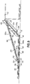
Figure 6 is a side elevation of a pipe-handling apparatus corresponding to a position ofFigure 3 ; -
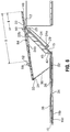
Figure 7 is an enlarged, perspective view of a carrier useful in a pipe-handling apparatus in a position as shown inFigure 3 ; -
Figure 8 is another perspective view of the carrier ofFigure 7 ; -
Figure 9 is an enlarged perspective view of a pipe control system useful in a pipe-handling apparatus; -
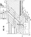
Figure 10 is another view of the pipe control system ofFigure 9 in another stage of operation; -
Figure 11 is another view of a pipe control system ofFigure 9 in another stage of operation; and -
Figure 12 is a sectional view along line I-I ofFigure 9 . - The detailed description set forth below in connection with the appended drawings is intended as a description of various embodiments of the present invention and is not intended to represent the only embodiments contemplated by the inventor. The detailed description includes specific details for the purpose of providing a comprehensive understanding of the present invention. However, it will be apparent to those skilled in the art that the present invention may be practiced without these specific details.
- In
Figures 1 to 3 there is shown a pipe-handling apparatus 10 for conveying pipe from a ground-supportedpipe rack 11 onto thefloor 12 of adrilling rig 14. - Pipe-
handling apparatus 10 includes, as main components, aramp 15 and amain support structure 16 that may include one ormore catwalks moveable pipe carrier 22.Main support structure 16 may be mounted on aground surface 13 and ramp 15 interconnectsmain support structure 16 of the apparatus withfloor 12 of the drilling rig.Pipe racks 11 can be positioned adjacent the main support structure to hold a supply, or receive,pipe joints 20.Pipe joints 20 are passed between the drilling rig and the pipe racks bypipe carrier 22, the details of which will be more fully disclosed hereinafter. - Pipe-
handling apparatus 10 includes a drive system for moving pipe carrier between a lower position (Figures 1 and4 ), a transitional position (Figures 2 and5 ) and an elevated position (Figures 3 and6 ). In the following discussion, the term "ramp end" is the end of the pipe carrier adjacent the ramp, while the "far end" of the pipe carrier is the end opposite to the ramp end. In the illustrated embodiment, the drive system may be based on a cable-drive including, for example, a winch that may provide high-speed operation. In the illustrated embodiment, spaced-apartcables 24 are roved aboutupper sheaves 25 and each cable includes amarginal end 24a wound about awinch drum 29 and anopposed cable end 24b attached topipe carrier 22. A plurality ofcables 24 may be used for redundancy, but of course one cable could be used if desired. - The drive system further includes a carrier far end elevation assembly including a
lift arm 30 journaled at 31 adjacent the far end of the pipe carrier.Carrier 22 andlift arm 30 ride along atrack 34 onmain structure 16 during elevation and lowering ofcarrier 22, for example as may be facilitated byrollers track 34. -
Lift arm 30 may take various forms. In the illustrated embodiment, the lift arm includes a pair of side beams of fixed length connected by cross members, but other forms may be useful such as one center beam, a pair of separate beams, or one or more hydraulic cylinders. -
Track 34 may be positioned in a longitudinally extending, upwardlyopening recess 35 for accommodating thepipe carrier 22 with its upper surface substantially flush withcatwalks -
Ramp 15 is formed to accept and support the ramp end ofcarrier 22 as it moves thereover through its various operational positions relative to the rig floor. In the illustrated embodiment,ramp 15 includes parallel, spaced-apart, openended track members 40 and 41 that may be connected by aweb 47 or other means to hold them in spaced apart configuration.Ramp 15 further includes anupper end 50 including a bearing surface capable of supporting movement of carrier thereover. The lower ramp end ofpipe carrier 22 includesopposed rollers 48. The rollers can ride intotrack members 40, 41 through their open ends and are received in low-friction relationship within theopposed track members 40 and 41, whencarrier 22 rides alongramp 15. Anunderside 22a of carrier is formed to ride overupper end 50, whenrollers 48 exit the upper open ends oftrack members 40,41, thus allowing further extension of the carrier over the drill floor. The side edges ofupper end 50 can be raised relative to the bearing surface to maintain centering of the carrier on the ramp as it rides thereover. - To move the carrier between the lower position and the elevated position,
winch 29 can be operated to pull oncables 24, which in turn pull on the carrier. From the position ofFigure 4 , wherecarrier 22 is positioned inrecess 35, this pulling force lifts the ramp end of the carrier out of the recess and movesrollers 48 ontoramp 15, which entertracks 40, 41. Continued pulling force by thewinch pulls carrier 22 andlink arm 30 alongtrack 34 until the end of the lift arm, forexample rollers 32, are stopped, as by dropping into apocket 34a in the track, as shown inFigure 5 . When this occurs with continued pulling force bywinch 29,lift arm 30, through its journaled connection at 31 and from a pivot created by the end of the lift arm pivoting against their stopped position (i.e.rollers 32 inpocket 34a), swings pivotally up to lift the far end ofpipe carrier 22 from the lower position through an arc vertically upward and horizontally toward the rig structure, as illustrated inFigures 1 to 6 .Cables 24 may be connected to the underside ofpipe carrier 22 a distance D from the carrier's ramp end to permit the carrier to be pulled forward by the cables overupper end 50 of ramp. In the illustrated embodiment,cables 24 are connected to carrier at apoint 47a that is spaced distance D from the ramp end which is greater than the distance D' that ramp is desired to be pulled pastupper end 50 of the ramp. Thus,winch 29 can create a pulling force to raisecarrier 22 upwardly fromstructure 16 and extend the carrier past the ramp over the drill floor. - In one embodiment, illustrated in
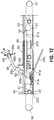
Figure 12 ,carrier 22 may include a plurality ofconnection points cables 24 may be connected. Since cable life may be limited by travel about sheaves, cable life may be extendable by changing from one connection point, for example 47a, to another connection point, forexample point 47b, so that two different areas along the cable may be driven oversheaves 25 during periods of the cable operational life. -
Carrier 22 includes an upper surface area thereof formed in a configuration so that a pipe joint 20 received therein gravitates to a lowermost, centrally located, cradled position, as illustrated by the various drawings. In particular, the carrier upper surface includes an elongate indentation or trough defined by rampedside surfaces 51, 51'.Carrier 22 carries apipe stop member 52 that acts to support a pipe joint positioned on the carrier, for example to prevent it from sliding downcarrier 22 when it is in the elevated position ofFigures 3 and6 . - With reference also to
Figure 12 ,pipe stop member 52 can also be formed to act as a push device to abut against the pipe and push it axially alongcarrier 22. For example,pipe stop member 52 can be formed to ride along aslot 53 formed betweensurfaces 51, 51'. In the illustrated embodiment,pipe stop member 52 is driven by anendless cable 54 for movement along the carrier.Pipe stop member 52 includes aslide 55 formed to engage and ride at least along a length ofslot 53.Cable 54 connects to slide below the upper surface of the carrier. Asheave 56 andwinch 57drive cable 54 to pull onslide 55, and therebypipe stop member 52, to move along the carrier.Winch 57 may have a centering V-shaped drum profile to maintaincable 54 in a centered position during operation. -
Pipe stop member 52 can, in addition if desired, include a pipe pull feature. In such an embodiment, the pipe stop member can include a pipe engagement device that engages a pipe, when the pipe is positioned in carrier, to move the pipe axially with the stop member. A pipe engagement device can take various forms. It may be useful to form the pipe engagement device to be operable to engage a pipe or release a pipe automatically with operation of the slider, rather than requiring manual operation of the device. In one embodiment shown inFigure 12 , a pipe engagement device includes anarm 59 connected to pipe stopmember 52 that can be driven between a position latching over a pipe and a position retracted from engagement with a pipe. The arm is driven between these latching and retracted positions automatically by movement of the pipe stop member. In the illustrated embodiment,pipe stop member 52 is mounted on asleeve 60 that is engaged, but slidably moveable betweenstops 61a on a drivecable attachment member 61.Arm 59 is connected viapivotal connections 62 and abrace arms sleeve 60 andmember 61.Relative movement sleeve 60 andmember 61, therefore drives pivotal movement of the arm. As will be appreciated, the weight of a pipe onstop 52 andsleeve 60 to be held in place whilemember 61 moves first relative to and withinsleeve 60 when pulled bycable 54.Stops 61a limit relative movement ofmember 61 within the sleeve and will eventually cause movement ofmember 61 to be transmitted tosleeve 60. Whenmember 61 is moved along direction A relative tosleeve 60,arm 59 will be retracted, arrow A1, and alternately, whenmember 61 is moved along direction B relative tosleeve 60,arm 59 will be brought around, arrow B1, and, if a pipe is positioned in carrier, latched over the pipe. The configuration of the stop, the sleeve and the arm with the drive system ofcable 54 can be arranged so that movement in direction A can cause thepipe stop member 52 to move toward ramp end (in a pushing configuration) and movement in direction B can cause stopmember 52 to move along the carrier toward the carrier's far end, which is the direction in which pipe pulling would be most useful. Such an arrangement may be useful where pipes are handled that are of insufficient weight to move easily by gravity along the carrier. Alternately, or in addition, such an arrangement may be useful where it is necessary to move a pipe along the trough to be better positioned, for example, relative to pipe-handling apparatus. Withoutarm 59 the carrier may have to be elevated to slide the pipe by gravity. In one embodiment,connections 62 may be removable so thatarm 59 can be removed frompipe stop member 52 if it is not needed in any particular operation. In the illustrated embodiment,return 59a is removably connected byconnection 64 that permits the return to be removed from the end of the arm and, if desired, inverted and stored out of an operational position. -
Arm 59 can be sized such thatreturn 59a is spaced fromstop member 52 to engage under the change in diameter at the end of a pipe joint connection.Return 59a can include a rounded orangular notch 59b to fit over the cylindrical outer surface of a pipe. - Opposed,
parallel catwalks carrier 22.Catwalks -
Ramp 15 may be hinged tomain support structure 16 through, for example, abearing 45 that elevates the axial centerline of the spaced-apart hinge pins, one of which is seen at 42, an amount to enable the ramp to be folded back ontocatwalks Carrier 22 andmain support structure 16 may be formed of main beams, forexample beams - Movement of
pipe sections 20 between the pipe rack and the carrier can be quite dangerous and there may be a risk of a pipe actually falling off the carrier, while it is in transition or while it is elevated. Thus, a present pipe-handling apparatus may include any of various components of a pipe control system. In the illustrated embodiments, a pipe control system is shown including a pipe-dumping apparatus, an indexing apparatus, and a lateral stop gate apparatus. A pipe control system may include any or all of these or other features, as desired. - Looking to the details of
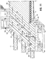
Figures 7 to 11 , a pipe-dumping apparatus is shown includingkickers 68 and 68' located at spaced-apart locations alongpipe carrier 22.Kickers 68, 68' can take various forms and modes of operation.Kickers 68 operate on oneside surface 51 of the carrier, while kickers 68' operate on the other 51'. In the illustrated embodiment, each kicker is mounted in arecess 71 and has anupper surface 70 formed to coincide generally with or be recessed below the V-shaped, the upper surface of the carrier indentation formed bysurfaces 51, 51'.Upper surface 70 is formed on abody 71 connected to a drive (cannot be seen clearly). The drive may be actuated to movekicker surface 70 to protrude abovesurface 51, 51' in which it is mounted to thereby abut against a pipe positioned in the indentation. Thus, a pipe in the carrier can be rolled out of the carrier away from the kicker. The kickers on one side, for example allkickers 68, may be operated in unison such that they together act on a pipe while the other kickers, for example 68' remain inactive. When a pipe is being loaded to carrier, thesurfaces 70 of all of the kickers remain flush with or recessed below thesurfaces 51, 51' to avoid interference with pipe loading. As an example, in one embodiment, the drive includes pivot pins and hydraulic cylinders for the kickers. For example, the kickers are mounted on pivot pins and actuated by a hydraulic cylinder mounted into the beams of the carrier. When the cylinder is retracted, the kicker is pulled upwards and out around its pivot point. When they are deactivated, the kickers are returned flush with rampedsurfaces 51, 51' so thestop member 52 can pass smoothly over them. - A pipe control system may further include a pipe indexing apparatus, including for
example indexers 75, 75' located at spaced-apart locations along cat walks 38, 39.Indexers 75, 75' can take various forms and modes of operation, but act to urge movement of the pipes along the catwalks into or out of the carrier. A pipe indexing apparatus, can therefore replace manual operators such that personnel need not be in this dangerous area. In the illustrated embodiment, indexers 75 operate on onecatwalk 38, while indexers 75' operate on the other. In the illustrated embodiment, each indexer has anupper surface 76 formed to be flush with or recessed below its catwalk upper surface.Upper surface 76 is formed on abody 77 connected to adrive mechanism 78 that permits at least one end of each indexer to be raised to protrude above the catwalk surface. A drive mechanism for the indexers can include hydraulic cylinders to drive each end of each indexer, which when activated push an end of the indexer up along guides. An indexer may, therefore, abut against and move a pipe positioned on the catwalk. As will be appreciated, the end of the indexer that is protruded above the catwalk surface will determine in which direction the pipe will roll. Thus, the indexers on one side of the carrier can be selected to operate to either move pipes into or away from the carrier or both, since in most operations the pipes will be moved to and from the pipe racks on both sides of the carrier repeatedly. The indexers on one side, for example allindexers 75, may be operated in unison, as by use of connected plumbing for the hydraulic cylinders, such that they together act to control pipe movement. - In one embodiment, shown in
Figure 7 , the pipe indexing apparatus can include stoppins 80 positioned adjacent a pipe rack carrying the supply of pipe joints. Stop pins 80 can be mountable, possibly releasably mountable, in a position on the catwalk overlapping the operational area traced by indexers, such as indexers 75' in the illustrated embodiment, by approximately one pipe diameter.Pins 80 can be formed to hold back the supply of pipe joints, as by coordinated tilting ofpipe rack 11 and selecting the height ofpins 80, so that pipe joints on the rack tend to roll againstpins 80 and, therefore, be in a position to be acted upon by the indexers. In this pipe indexing apparatus, thedrive 78 is selected to permit the upper surfaces of the indexers to be raised a suitable height with respect topins 80 to lift a pipe, or allow a pipe to roll, over the pins. In one embodiment, the pipes stored on a sloped pipe rack can roll up againstpins 80 and indexers 75' can then lift the first most pipe over the pins. The back surface of the outboard end of the indexers can include atongue 77a that extends down and prevents the next adjacent pipe joint from rolling forward under the elevated indexer. When the indexer is retracted, the next available pipe is free to roll up against the pins. Meanwhile the first pipe has rolled down the indexer, across the catwalk and into the carrier trough. - A pipe control system may further include a lateral stop gate apparatus, that acts to prevent accidental lateral movement of a pipe out of the carrier indentation either during movement of the carrier (
Figure 7 ) or during loading of a pipe (Figure 9 ). The lateral stop pin apparatus can take various forms and modes of operation, but includes a structure on the carrier, the structure being moveable between a position protruding above the upper surface of the carrier (to prevent a pipe rolling therepast over the upper surface of the carrier) and a position out of the way of rolling movement of pipes over the surface of the carrier, which may be, for example, recessed in apertures or slots in the upper surface or may be positioned at the side of the carrier. The structure may be, for example, one or more elongate or short walls, a plurality of pins, posts, etc. To act against rolling of an elongate member such as a pipe joint 20, it will be appreciated that the gate structure may be needed at at least a plurality of spaced apart position along the carrier. In the illustrated embodiment, the lateral stop gate apparatus includes raisable pins 84, 84' located at spaced-apart locations along pipe carrier on either side of its elongate indentation.Pins 84 operate on one side ofcarrier 22, while pins 84' operate on the other. In the illustrated embodiment, each pin is positioned in anaperture 86 opening from carrier upper surface and is formed to be moveable by adrive 87 between a position flush with (or recessed below) the carrier upper surface (shown bypins 84 inFigure 9 ) and a position protruding above the upper surface of the carrier (shown by pins 84' inFigure 9 ). In one embodiment, pins 84, 84' are raised by a hydraulic cylinder with a linkage arrangement providing mechanical advantage. The linkage allows a short stroke, compact cylinder to be used to raise the pins. When the pins are protruding on the upper surface of the carrier, a pipe joint 20 cannot easily roll therepast. As such, the pins can be raised or lowered to control against movement of a pipe. For example, during pipe loading, as shown inFigure 9 , the pins on one side can be lowered to allowed entry of a pipe therepast while the pins 84' on the other side are raised to prevent a pipe from rolling though the indentation and off the carrier. As another example, when moving the carrier or when it is elevated over the drilling floor, as shown inFigure 7 , thepins 84, 84' on both sides of the carrier can be raised to prevent all lateral movement of the pipe off the carrier.Pins 84, 84' can be positioned adjacentsloped surfaces 51, 51' so that any pipe butting against them will tend to fall back into the carrier indentation formed by the sloped surfaces. The pins on one side, for example all pins 84, may be operated in unison such that they together act to control pipe movement. - The pipe-handling apparatus may be controlled for operation of the various components and features thereof. It may be desirable to provide a control system that operates through programmed features to intelligently guide operations. This reduces the need for constant manual supervision and reduces the possibility of operator error. For example with reference to the illustrated embodiments, the controller may be programmed to accept a command such as "load" for loading a pipe to the carrier, wherein the controller ensures that pins 84 are raised, pins 84' are recessed and indexers 75' lift a pipe over pins 80. Additionally or alternately, the controller may operate to control the speed of operations, for example of
winch 29, so that the apparatus operates with consideration to efficiency and safety. For example, in response to a command "carrier lift" the winch may be operated to raise the carrier first with a soft start and then quickly to bring the carrier to a position adjacent the upper end oframp 15, but when the controller determines that theramp 15 is adjacent the drilling floor, the controller may act to automatically slow the winch to slowly bring the carrier in over the rig floor to a final position. The controller may include a wireless transmitter, such as a hand held panel or joystick transmitter box, for transmitting operator commands. Such a transmitter may include all of the necessary switches and control manipulators to start the motor, and run all functions so that a person controlling the pipe-handling apparatus may be remote from the apparatus, for example on the rig floor or in a rig control booth. A wireless receiver may be used to receive the transmitted signals and relay them to a connected computer. The computer may support software designed to interpret the requests from the transmitter and control all of the functions of the apparatus. For apparatus control, there may also be an operator interface screen to indicate machine status and error conditions. To monitorwinch 29 operation, a rotational encoder may be used that tracks rotation of the winch drum and converts that to distance moved by the cable and, thereby, the carrier. - The controller may include feedback safety mechanisms or systems. For example, in one embodiment,
main support structure 16 includes a detection beam system in communication with the controller. Detection beam system is selected to monitor themain support structure 16 and feedback to the controller a shutdown signal should the detection beam sense problematic movement on the main support structure, for example movement other than that of pipes rolling and systems normally operating. For example, the detection beam system may include a plurality ofemitters 90 and a corresponding plurality ofreceivers 92 mounted about the structure, for example, overcatwalks signals 94, such as light beams. A detection beam system such as this may be used to ensure that the pipe-handling apparatus cannot operate, at least through certain steps, when a person is sensed on the catwalks, as by breaking the curtain of signals 94. - The controller may also record cable operational hours and provide an alert to the apparatus operator when it is desired to move cables from one connection point to another, for example from
connection point 47a toconnection point 47b, as previously described, or to replace the cables as required. - In operation, the apparatus is delivered to a drilling site and positioned adjacent a drilling rig.
Ramp 15 may be unfolded into an operative position, such as inFigure 1 , set against the rig so that upper end is adjacent the rig floor. The ramp may be allowed to rest freely on the rig substructure drilling floor. In this way, the ramp may float with the rig, as may be useful to accommodate height changes of the rig as may occur during normal rig operations. In one embodiment, safety chains (not shown) may be secured between the ramp and the rig to avoid a problem should supportstructure 16 get bumped. The pipe-handling apparatus may, if desired, be constructed to best work with the rig, as by selection of the lengths of any of the ramp, the carrier or the lift arm, with consideration as to various parameters such as the nature of pipe to be handled, the height of the rig, etc. -
Pipe racks 11 are attached on either side of themain structure 16 so that new pipe to be used can be placed on one side of the apparatus while pipe which comes out of the hole can be placed on the rack on the opposed side of the structure. When the drilling operation commences, drill pipe, or other tubular goods, are rolled from the pipe rack and into the carrier. The racks can be tilted so that the tubulars roll by gravity againstpins 80 and are acted upon bypipe indexers 75. Thepins 84, 84' of a lateral stop gate apparatus may be operated to control lateral movement of the tubular with respect tocarrier 22, during loading and during movement ofcarrier 22. - A motor and pump energizes
winch 29 that pulls thecables 24, thereby elevating the pipe carrier from the position ofFigure 1 into the positions ofFigures 2 and3 , as described previously. The apparatus for operation may also include a controller, instrumentation or features for operational feedback, power supplies, motor control switchgear, hydraulic power pack with hydraulic reservoir, etc., as will be appreciated. -
Carrier 22 moves alongramp 15 withrollers 48 moving alongtracks 40, 41. When the carrier reaches the upper open ends of the tracks, the cables continue to pull the carrier up overupper end 50 of the ramp. As such,carrier 22 is extended overfloor 12 towards the hole center. During or after the carrier is moved overfloor 12,pipe stop member 52 can be actuated to slide the pipe axially along the carrier to enhance access or movement of the pipe. These actions position the end of a tubular in close proximity to the elevators or other rig components. The lengths, heights and configuration of the components of the pipe-handling apparatus can be selected such that the end of the pipe carrier is brought to a position abovedrilling floor 12 that is convenient for pipe handling. This tubular can then be used by incorporation into the drill string, casing string, etc. Alternately or in addition,arm 59 can be retracted from engagement with the tubular being handled, as by movement ofpipe stop member 52. - To move the carrier off the drill floor, the
winch 29 can be reversed to generate slack incables 24.Winch 29 is caused to play out the cable in a controlled manner allowing gravity to retract the carrier and lift arm back into their retracted, lower position. If further tubulars are required to be moved from theracks 11 to the drill floor, another pipe joint can be loaded and elevated to the drill floor. Thewinch 29 can be of a high speed rating so that the pipe can be brought to the drill floor rapidly to correspond with preferred tripping operations. In one embodiment, the time to lift or retract may be around 10 to 60 seconds. To keep up with a tripping and laying down process, the time to lift or retract may be less than 30 seconds and generally less than 20 seconds. - When the time comes to remove a pipe string from the hole, the string may be broken out by disconnecting the tubular joints and placing an end thereof on the
pipe carrier 22 until an advancing end thereof abuts againstpipe stop member 52. As the pipe is lowered onto the carrier or prior thereto,pipe stop member 52 can be reversed along the carrier to a position just behind that where the pipe would stop when being lowered onto the carrier by the blocks and elevator in the derrick. The ramped surfaces of the trough act to guide the pipe along the carrier and pins 84, 84' may be elevated as a safety precaution. Just prior to releasing the elevators the pipe stop is moved forward to support the end of the pipe so that it doesn't slide back uncontrolled. Once the elevators are removed, the pipe is controllably allowed to slide back or is pulled back by thepipe stop member 52 so that the entire pipe is on the carrier.Arm 59 can be operated to engage a pipe introduced ontocarrier 22 and pull it back. Ifarm 59 is connected to pipe stopmember 52 in an operative manner, it may be oriented to engage over or retract from a pipe on the carrier, depending on the operation to be completed. This may be achieved by drivingcable 54. - Thereafter,
pipe carrier 22 is retracted intorecess 35 ofmain structure 16 whereupon pins 84, 84' are lowered and the automatic pipe dumping apparatus, including eitherkickers 68 or kickers 68', causes the joint of pipe to move out of the elongated indentation of the carrier.Indexers 75 or 75' may be actuated to move the pipe across the catwalks onto either ofpipe racks 11, as desired.Pipe stop 52 and/orarm 59 can be operated to reposition a pipe at any time. - When it is time to relocate the pipe-handling apparatus,
ramp 15 may be folded abouthinge pin 42 and the entire apparatus may be transported to the next drill site where it is again erected in the manner described above. During transport of the apparatus, the pipe racks may be folded 90° adjacent the main support structure. The racks may be supported on integral shipping hooks integrated into the side of the main support structure.
Claims (20)
- Pipe-handling apparatus (10) for moving a pipe (20) to and from a drilling floor (12) of a drilling rig, the pipe-handling apparatus comprising:a main support structure (16),a ramp (15) having an upper end (50) and being extendable between the main support structure and the drilling floor,a fixed-length pipe carrier (22) mounted on the main support structure for moving relative thereto between a lower position and an elevated position over the ramp, the carrier including a ramp end adjacent the ramp, a far end, and an elongate indentation on its upper surface to accommodate a pipe therein,a lift arm (30) including a first end and a second end, the lift arm (30) being pivotally connected at its first end adjacent the far end of the carrier (22) and operable below the carrier to lift and support the carrier (22) in the elevated position,a track (34) on the main support structure (16) for supporting axial sliding motion of the carrier (22) and the lift arm (30) therealong, the track (34) including a stop (34a) for limiting axial movement of the second end of the lift arm (30) along the track toward the ramp (15), anda drive system (24, 24a, 24b, 25, and 29) for pulling the carrier (22) from the lower position to ride along the ramp (15) to the elevated position, the drive system adapted to pull the lift arm (30) along the track (34) until it is stopped against the stop in the track (34) and to continue pulling to cause the lift arm (30) to be pivoted up about the stop (34a) to lift the carrier into the elevated position, characterized in that:the drive system (24, 24a, 24b, 25, 29) includes a cable-drive which includes a winch (29) and a cable (24) connected between the carrier (22) and the winch (29), the cable (24) arranged to pull the carrier (22) up along the ramp (15);the ramp (15) is configured to accept and support the ramp end of the carrier (22) as the ramp end of the carrier (22) moves over the ramp; and the ramp (15) includes a bearing surface on its upper end capable of supporting movement of the carrier (22) thereover; andthe pipe carrier (22) and the drive system (24, 24a, 24b, 25 and 29) are selected to permit the pipe carrier (22) to ride up and extend past the end of the ramp (15) over the drilling floor (12) such that the ramp end of the fixed-length pipe carrier (22) is extended past the upper end of the ramp (15) and over the drilling floor (12) when in the elevated position.
- The pipe-handling apparatus of claim 1 characterized in that the main support structure (16) includes one or more catwalks (38, 39) on an upper surface thereof.
- The pipe-handling apparatus of claim 1 characterized in that the main support structure (16) is formed to accept a pipe rack (11) positioned adjacent thereto to hold a supply of pipe.
- The pipe-handling apparatus of claim 1 characterized in that the cable (24) is connected to the underside of the pipe carrier (22) a distance from the carrier's ramp end to permit the carrier (22) to be pulled forward by the cable (24) over an upper end of ramp (15).
- The pipe-handling apparatus of claim 1 characterized in that the cable (24) is connected to the carrier (22) at a point spaced a distance from the ramp end greater than a desired distance that the ramp (15) is desired to be pulled past an upper end of the ramp (15).
- The pipe-handling apparatus of claim 1 further comprising a plurality of connection points on the carrier (22) through which the cable (24) may be selectably connected.
- The pipe-handling apparatus of claim 1 characterized in that the carrier (22) and the lift arm (30) include low friction members to facilitate riding along the tract (34).
- The pipe-handling apparatus of claim 1 characterized in that the lift arm (30) is of a fixed length.
- The pipe-handling apparatus of claim 1 characterized in that the track (34) is positioned in a longitudinally extending, upwardly opening recess on main support structure (16).
- The pipe-handling apparatus of claim 9 characterized in that the pipe carrier (22) is positionable in the recess with its upper surface substantially flush with a catwalk (38, 39) on the main support structure (16).
- The pipe-handling apparatus of claim 1 characterized in that the stop of the track (34) is a pocket formed to capture the second end of the list arm (30).
- The pipe-handling apparatus of claim 1 characterized in that the second end of lift arm (30) carries rollers.
- The pipe-handling apparatus of claim 1 further comprising a pipe stop member (52) positioned on the carrier (22) to support a pipe positioned on the carrier (22).
- The pipe-handling apparatus of claim 13 characterized in that the pipe stop member (52) is axially moveable along the carrier (22).
- The pipe-handling apparatus of claim 14 further comprising a slot formed in the elongated indentation and characterized in that the pipe stop member (52) is mounted through slot and connected to an endless cable for (24) movement along the carrier (22).
- The pipe-handling apparatus of claim 13 further comprising a grabber arm on pipe stop member (52) to permit pulling engagement on a pipe supported on the carrier (22).
- The pipe-handling apparatus of claim 1 further comprising a lateral stop gate on the carrier (22).
- The pipe-handling apparatus of claim 17 characterized in that the lateral stop gate includes a plurality of raisable pins (84, 84') carried with the carrier (22) and positioned along each side of the carrier (22).
- The pipe-handling apparatus of claim 1 further comprising a pipe feeding mechanism for positioning a pipe for pick up and moving one pipe at a time to the carrier (22).
- The pipe-handling apparatus of claim 19 characterized in that the pipe feeding mechanism includes a pipe supply stop for positioning a first pipe ready for pick up and an indexing device for moving the first pipe past the pipe supply stop towards the carrier (22).
Applications Claiming Priority (2)
| Application Number | Priority Date | Filing Date | Title |
|---|---|---|---|
| US10/908,951 US7832974B2 (en) | 2005-06-01 | 2005-06-01 | Pipe-handling apparatus |
| PCT/CA2006/000904 WO2006128300A1 (en) | 2005-06-01 | 2006-05-30 | Pipe-handling apparatus |
Publications (3)
| Publication Number | Publication Date |
|---|---|
| EP1888872A1 EP1888872A1 (en) | 2008-02-20 |
| EP1888872A4 EP1888872A4 (en) | 2011-06-22 |
| EP1888872B1 true EP1888872B1 (en) | 2017-10-04 |
Family
ID=37481190
Family Applications (1)
| Application Number | Title | Priority Date | Filing Date |
|---|---|---|---|
| EP06752742.4A Expired - Fee Related EP1888872B1 (en) | 2005-06-01 | 2006-05-30 | Pipe-handling apparatus |
Country Status (7)
| Country | Link |
|---|---|
| US (2) | US7832974B2 (en) |
| EP (1) | EP1888872B1 (en) |
| CN (2) | CN101278103B (en) |
| MX (1) | MX338370B (en) |
| RU (1) | RU2405907C2 (en) |
| UA (1) | UA91550C2 (en) |
| WO (1) | WO2006128300A1 (en) |
Families Citing this family (105)
| Publication number | Priority date | Publication date | Assignee | Title |
|---|---|---|---|---|
| US7431550B2 (en) * | 2002-10-04 | 2008-10-07 | Technologies Alliance | Pipe handling apparatus for pick-up and lay-down machine |
| US7552775B2 (en) * | 2005-05-02 | 2009-06-30 | Weatherford/Lamb, Inc. | Tailing in and stabbing device and method |
| US7832974B2 (en) * | 2005-06-01 | 2010-11-16 | Canrig Drilling Technology Ltd. | Pipe-handling apparatus |
| CA2535083C (en) * | 2006-02-01 | 2010-12-14 | Gerald Lesko | Pipe indexer/kicker |
| US20090053013A1 (en) * | 2007-08-20 | 2009-02-26 | Maltby Scott R | Portable drill pipe handling apparatus for use with oil and gas well drilling rigs |
| US8033779B2 (en) | 2008-01-31 | 2011-10-11 | Canrig Drilling Technology Ltd. | Pipe handling apparatus and methods |
| US8016536B2 (en) * | 2008-04-04 | 2011-09-13 | Canrig Drilling Technology Ltd. | Pipe-handling apparatus and methods |
| CA2639706C (en) * | 2008-09-17 | 2015-06-30 | Hunterwood Technologies Ltd. | Catwalk for a drilling rig |
| US8210279B2 (en) * | 2008-12-02 | 2012-07-03 | Schlumberger Technology Corporation | Methods and systems for tripping pipe |
| US7992646B2 (en) * | 2008-12-30 | 2011-08-09 | Weatherford Canada Partnership | Horizontal offline stand building system |
| NO333186B1 (en) * | 2009-01-27 | 2013-03-25 | Standlifter Holding As | Method and apparatus for transporting rudder sections between a magazine and a drill bit |
| US8511963B1 (en) * | 2009-02-12 | 2013-08-20 | Billy Bunch | Pipe handling assembly |
| US9422779B1 (en) * | 2009-02-12 | 2016-08-23 | Justin Bunch | Pipe handling assembly |
| CA2768713C (en) * | 2009-07-29 | 2014-09-16 | Markwater Handling Systems Ltd. | Pipe kicker/indexer for pipe handling systems |
| CA2713676C (en) * | 2009-09-22 | 2015-04-14 | Nathan Crossley | Apparatus and method for handling tubulars |
| US8215888B2 (en) * | 2009-10-16 | 2012-07-10 | Friede Goldman United, Ltd. | Cartridge tubular handling system |
| US20110188973A1 (en) * | 2010-02-03 | 2011-08-04 | Tts Sense Canada Ltd. | Pipe handling system for a drilling rig |
| US20110226466A1 (en) * | 2010-03-19 | 2011-09-22 | Baker Hughes Incorporated | Electric Submersible Pump Service Truck |
| CA2737818C (en) * | 2010-04-27 | 2013-06-25 | Markwater Handling Systems Ltd. | Pivoting pipe handler for tender assisted drilling rigs |
| CN101936141A (en) * | 2010-08-16 | 2011-01-05 | 贵州航天凯宏科技有限责任公司 | Conveying equipment of petroleum drill pipe |
| CA2720802C (en) * | 2010-11-12 | 2015-10-20 | Rangeland Industrial Service Ltd. | An apparatus and method for handling pipe |
| CA2792116C (en) * | 2011-10-11 | 2019-11-12 | Warrior Rig Ltd. | Portable pipe handling system |
| US9063524B2 (en) * | 2011-11-08 | 2015-06-23 | Bartlett Power & Automation LLC | Control system for a pipe handling apparatus |
| CN102364037A (en) * | 2011-11-11 | 2012-02-29 | 贵州航天凯宏科技有限责任公司 | Manual pipe bridge equipment of oil drilling platform |
| US8899901B2 (en) | 2012-06-14 | 2014-12-02 | Warrior Energy Services Corporation | Pipe handling apparatus and method |
| US8950996B2 (en) * | 2012-06-14 | 2015-02-10 | Warrior Energy Services Corporation | Pipe handling apparatus and method |
| US9267342B2 (en) | 2012-06-14 | 2016-02-23 | Warrior Energy Services Corporation | Pipe handling apparatus and method |
| US9243461B1 (en) * | 2012-01-17 | 2016-01-26 | Loadmaster Universal Rigs, Inc. | Catwalk mechanism and method for installing tubulars on a drill string |
| CN104136708B (en) * | 2012-02-22 | 2016-05-25 | 考克斯技术有限公司 | Drill pipe is sent to the device of rig |
| AR088739A1 (en) * | 2012-05-16 | 2014-07-02 | Miranda Diego | PIPE MOVEMENT EQUIPMENT CONFORMED BY A CHASSIS, AN INCLINED PLANE, EXTENSION TRAY AND SIDE KNIGHTS, HORSE ELEVATOR AND RELATED SUPPORT AND ELEVATION LEGS |
| CA2909192C (en) | 2012-05-25 | 2020-06-02 | T&T Engineering Services, Inc. | Service line transport and deployment system |
| US8899907B2 (en) * | 2012-06-21 | 2014-12-02 | Superior Energy Services-North America Services, Inc. | Pipe ejector mechanism and method |
| US9140080B2 (en) * | 2012-06-21 | 2015-09-22 | Superior Energy Services—North America Services, Inc. | Transportable single operator rig apparatus and method for optimizing drilling and/or completion |
| SE536564C2 (en) | 2012-06-28 | 2014-02-25 | Atlas Copco Rocktech Ab | Device and method for handling drill string components and rock drilling rigs |
| CN102787813B (en) * | 2012-08-18 | 2015-06-17 | 吉林大学 | Intelligent full-hydraulic power catwalk |
| US9187269B2 (en) | 2012-10-12 | 2015-11-17 | Chevron Phillips Chemical Company Lp | Polymeric pipe loading |
| CN102900386B (en) * | 2012-10-26 | 2015-01-07 | 扬州大学 | Automated ramp device |
| CA2833745C (en) | 2012-11-19 | 2020-12-15 | Key Energy Services, Llc | Methods of mechanized and automated tripping of rods and tubulars |
| CN102926685B (en) * | 2012-11-23 | 2014-07-16 | 吉林大学 | All-hydraulic automatic drilling tool conveying device for deep-well drilling rig |
| US9926719B2 (en) * | 2013-02-13 | 2018-03-27 | Nabors Drilling Technologies Usa, Inc. | Slingshot side saddle substructure |
| US9708861B2 (en) | 2013-02-13 | 2017-07-18 | Nabors Drilling Usa, Lp | Slingshot side saddle substructure |
| US9810027B2 (en) | 2013-02-13 | 2017-11-07 | Nabors Drilling Usa, Lp | Side saddle substructure |
| US9506302B2 (en) * | 2013-03-13 | 2016-11-29 | Forum Us, Inc. | System for attaching a gullwing to a catwalk |
| WO2014172770A1 (en) * | 2013-04-25 | 2014-10-30 | Custom Pipe Handlers Canada Inc. | Pipe handling apparatus and method |
| CN104420842B (en) * | 2013-09-11 | 2017-06-06 | 四川宏华石油设备有限公司 | A kind of cat road |
| US9617796B2 (en) * | 2013-10-04 | 2017-04-11 | Electro Mechanical Industries, Inc. | Cable management system |
| CN103510887B (en) * | 2013-10-14 | 2015-11-25 | 江苏如通石油机械股份有限公司 | Power fortune pipe device |
| US9528330B2 (en) | 2013-11-19 | 2016-12-27 | Tesco Corporation | System and method for transporting tubular onto a drilling rig |
| CN103615205A (en) * | 2013-12-11 | 2014-03-05 | 东营胜利慧岩石油装备有限公司 | Variable angle device |
| KR101544814B1 (en) | 2014-06-11 | 2015-08-17 | 대우조선해양 주식회사 | Drilling system using apparatus for moving other types pipe |
| US9624740B2 (en) * | 2014-06-26 | 2017-04-18 | Tammy Sue Molski | Hydraulic pipe handling apparatus |
| US10012038B2 (en) | 2014-07-15 | 2018-07-03 | Warrior Rig Technologies Limited | Pipe handling apparatus and methods |
| AU2014204515B2 (en) * | 2014-07-18 | 2017-12-21 | Exploration Drill Masters Chile S.A. | Semiautomated drill rod handling apparatus and method, hand-held haul plug spinner and haul plug combination and drill rod handling system with both |
| CN104495196A (en) * | 2014-11-18 | 2015-04-08 | 柳州市金旭节能科技有限公司 | Drill pipe conveying equipment |
| CA2977164C (en) * | 2015-02-24 | 2023-10-10 | Drillform Technical Services Ltd. | Transitioning pipe handler |
| DE112016000965T5 (en) * | 2015-02-27 | 2017-12-07 | Forum Us, Inc. | Sliding truss system |
| WO2016138007A1 (en) * | 2015-02-27 | 2016-09-01 | Forum Us, Inc. | Tubular pin control system |
| MX2017010525A (en) * | 2015-04-15 | 2017-11-13 | Forum Us Inc | Tubular handling system. |
| US9879442B2 (en) * | 2015-06-29 | 2018-01-30 | Nabors Industries, Inc. | Drilling rig column racker and methods of erecting same |
| CA3008397A1 (en) | 2015-11-16 | 2017-05-26 | Schlumberger Canada Limited | Automated tubular racking system |
| WO2017087350A1 (en) | 2015-11-16 | 2017-05-26 | Schlumberger Technology Corporation | Tubular delivery arm for a drilling rig |
| CA3008398A1 (en) | 2015-11-17 | 2017-05-26 | Schlumberger Canada Limited | High trip rate drilling rig |
| CN105507829B (en) * | 2016-01-18 | 2017-11-21 | 李晓峰 | A kind of workover rig for removing system automatically with tubing string is with automatically controlling operating platform |
| US11136836B2 (en) | 2016-04-29 | 2021-10-05 | Schlumberger Technology Corporation | High trip rate drilling rig |
| MX2018013254A (en) | 2016-04-29 | 2019-08-12 | Schlumberger Technology Bv | High trip rate drilling rig. |
| US11118414B2 (en) | 2016-04-29 | 2021-09-14 | Schlumberger Technology Corporation | Tubular delivery arm for a drilling rig |
| US10513895B2 (en) | 2016-04-30 | 2019-12-24 | Cameron International Corporation | Pipe transport system and method |
| WO2017192531A1 (en) * | 2016-05-02 | 2017-11-09 | Cameron International Corporation | Catwalk and crane system |
| US10081990B2 (en) | 2016-05-13 | 2018-09-25 | Forum Us, Inc. | Kicker system for tubular handling system |
| US10030455B2 (en) | 2016-05-14 | 2018-07-24 | Forum Us, Inc | Skate drive and tubular clamping system for a catwalk |
| CN105863528A (en) * | 2016-05-31 | 2016-08-17 | 青岛杰瑞工控技术有限公司 | Sliding intelligent equipment for transferring pipe column |
| WO2017214148A1 (en) | 2016-06-07 | 2017-12-14 | Nabors Drilling Technologies Usa, Inc. | Side saddle slingshot drilling rig |
| RU2019103656A (en) | 2016-07-13 | 2020-08-10 | Нэйборз Дриллинг Текнолоджи США, Инк. | MAST TOWER AND SUPPORT BASE |
| CN106429428A (en) * | 2016-07-27 | 2017-02-22 | 胜利油田胜利动力机械集团有限公司石油机械分公司 | Ground integrated conveyer |
| CN106639921B (en) * | 2016-07-27 | 2020-03-10 | 黑龙江精益诚石油机械有限公司 | Automatic pipe rod conveyor |
| US10584541B2 (en) | 2016-07-28 | 2020-03-10 | Nabors Drilling Technologies Usa, Inc. | Pipe handling apparatus |
| RU2753741C2 (en) | 2016-11-07 | 2021-08-23 | Нэйборз Дриллинг Текнолоджи США, Инк. | Mast tower of side saddle-shaped self-lifting drilling rig that is folded during transportation |
| CN106761475A (en) * | 2016-11-29 | 2017-05-31 | 大庆市汇通建筑安装工程有限公司 | Oil well operation pipe bridge runner device |
| EP3342974B1 (en) * | 2016-12-27 | 2020-04-15 | Drillmec S.p.A. | Manipulator apparatus for handling of perforation elements to and from a drilling floor |
| US10151157B2 (en) * | 2016-12-28 | 2018-12-11 | Forum Us, Inc. | Kicker and transfer assembly for a tubular handling system |
| WO2018132810A1 (en) | 2017-01-16 | 2018-07-19 | Nabors Drilling Technologies Usa, Inc. | Rig layout system |
| CN106869827B (en) * | 2017-04-21 | 2023-08-01 | 中曼石油钻井技术有限公司 | Self-walking type power catwalk and walking method thereof |
| US10597954B2 (en) | 2017-10-10 | 2020-03-24 | Schlumberger Technology Corporation | Sequencing for pipe handling |
| US10487592B1 (en) | 2018-05-03 | 2019-11-26 | Nabors Drilling Technologies Usa, Inc. | Multi-direction traversable drilling rig |
| US10724310B2 (en) * | 2018-06-08 | 2020-07-28 | Glider Products LLC | Integrated pipe handling system for well completion and production |
| US10214970B1 (en) | 2018-06-12 | 2019-02-26 | Nabors Drilling Technologies Usa, Inc. | Post and non-elongated substructure drilling rig |
| US10837238B2 (en) | 2018-07-19 | 2020-11-17 | Nabors Drilling Technologies Usa, Inc. | Side saddle slingshot continuous motion rig |
| CN108843259A (en) * | 2018-07-23 | 2018-11-20 | 北京四利通控制技术股份有限公司 | A kind of drilling tool transportation equipment |
| WO2020051705A1 (en) * | 2018-09-11 | 2020-03-19 | Drillform Technical Services Ltd. | Pipe handler apparatus |
| GB2595104B (en) | 2019-01-31 | 2023-04-19 | Nat Oilwell Varco Lp | Tubular string building system and method |
| CN110306942A (en) * | 2019-07-31 | 2019-10-08 | 山东泽元石油机械有限公司 | A kind of cat road machine |
| CN110306939A (en) * | 2019-07-31 | 2019-10-08 | 山东泽元石油机械有限公司 | One kind can the road Duan Chaimao machine |
| WO2021108110A1 (en) * | 2019-11-27 | 2021-06-03 | Nabors Drilling Technologies Usa, Inc. | Adjustable pipe handling system |
| US10995565B1 (en) * | 2019-12-18 | 2021-05-04 | Logan Industries International Corporation | Tubular handling tool |
| US11428056B1 (en) * | 2020-03-11 | 2022-08-30 | Forum Us, Inc. | Pipe puller for drilling and service rig pipe handlers |
| US11454069B2 (en) | 2020-04-21 | 2022-09-27 | Schlumberger Technology Corporation | System and method for handling a tubular member |
| CN115917114A (en) | 2020-07-06 | 2023-04-04 | 内搏斯铂井技术美国公司 | Robot pipe fitting handling device system |
| US11643887B2 (en) * | 2020-07-06 | 2023-05-09 | Canrig Robotic Technologies As | Robotic pipe handler systems |
| US11408236B2 (en) | 2020-07-06 | 2022-08-09 | Canrig Robotic Technologies As | Robotic pipe handler systems |
| CN116113750A (en) | 2020-09-01 | 2023-05-12 | 坎里格机器人技术有限公司 | Tubular member handling system |
| US11873685B2 (en) | 2020-09-01 | 2024-01-16 | Nabors Drilling Technologies Usa, Inc. | Side saddle traversable drilling rig |
| GB2598912A (en) * | 2020-09-17 | 2022-03-23 | Oiltech Group Ltd | Drill rig tube delivery apparatus and method |
| CA3197811A1 (en) * | 2020-11-20 | 2022-05-27 | Graham Patrick Little | A rod handling system for drilling rigs |
| US11557887B2 (en) * | 2020-12-08 | 2023-01-17 | Yantai Jereh Petroleum Equipment & Technologies Co., Ltd. | Cable laying device |
| CN113077639B (en) * | 2021-03-30 | 2022-03-29 | 四创电子股份有限公司 | Ramp intelligent traffic control method based on radar and lifting type height limiting frame |
Family Cites Families (74)
| Publication number | Priority date | Publication date | Assignee | Title |
|---|---|---|---|---|
| US3128893A (en) * | 1964-04-14 | Boat handling and loading assembly | ||
| US2643006A (en) | 1949-09-28 | 1953-06-23 | William R King | Automatic pipe handler |
| US2631741A (en) * | 1950-06-29 | 1953-03-17 | Tucker Samuel Joseph | Apparatus for handling drill pipes |
| US2790683A (en) * | 1954-01-08 | 1957-04-30 | Walter J Clark | Elevatable drill pipe stacking apparatus |
| US3169645A (en) | 1961-08-11 | 1965-02-16 | Sr Richard B Freeman | Drill pipe and collar laying down machine |
| US3159286A (en) | 1963-10-17 | 1964-12-01 | Sr Richard B Freeman | Drill pipe handling apparatus |
| US3217900A (en) | 1964-04-06 | 1965-11-16 | Herman W Kupetzky | Mechanism for missile transfer |
| US3307719A (en) | 1965-04-23 | 1967-03-07 | Tag A Long Trailers Inc | Floating ramp |
| US3494483A (en) | 1968-10-04 | 1970-02-10 | James E Smart | Portable pipe handling apparatus |
| FR2041648A5 (en) | 1969-05-14 | 1971-01-29 | Inst Francais Du Petrole | |
| CA967502A (en) * | 1969-06-17 | 1975-05-13 | Jacques Bomstein | Devices for the complete transfer of a load between two separate supports |
| FR2126583A5 (en) * | 1971-02-11 | 1972-10-06 | Merlin Gerin | |
| US3706347A (en) | 1971-03-18 | 1972-12-19 | Cicero C Brown | Pipe handling system for use in well drilling |
| US3780883A (en) | 1971-03-18 | 1973-12-25 | Brown Oil Tools | Pipe handling system for use in well drilling |
| US3785506A (en) | 1971-09-10 | 1974-01-15 | Roger A Crocker | Drill pipe handling apparatus |
| US3810553A (en) | 1972-08-31 | 1974-05-14 | R Crocker | Pipe handling device |
| US3883820A (en) | 1973-04-27 | 1975-05-13 | Coherent Radiation | Gas laser having improved multiple-part resonator adjustment |
| US3840128A (en) | 1973-07-09 | 1974-10-08 | N Swoboda | Racking arm for pipe sections, drill collars, riser pipe, and the like used in well drilling operations |
| FR2287951A1 (en) | 1974-10-16 | 1976-05-14 | Kieserling & Albrecht | RIGOLE ENCLOSED ON NUTTING MACHINES AND DRESSING MACHINES |
| US4051775A (en) | 1975-10-23 | 1977-10-04 | Watson Edward F | Apparatus for automatically positioning with respect to a predetermined operation station |
| FR2344417A1 (en) | 1976-03-19 | 1977-10-14 | Bennes Marrel | SEMI-TRAILER PERFECTED FOR THE HANDLING AND TRANSPORT OF STANDARD BOXES OR CONTAINERS |
| US4067453A (en) * | 1976-04-19 | 1978-01-10 | Western Gear Corporation | Pipe delivery system |
| US4129221A (en) | 1976-04-30 | 1978-12-12 | Western Gear Corporation | Pipe handling apparatus |
| US4051956A (en) | 1976-07-26 | 1977-10-04 | Teague J T | Horizontal pipe handling apparatus |
| US4235566A (en) | 1978-12-04 | 1980-11-25 | Beeman Archie W | Pipe-conveying catwalk |
| US4347028A (en) * | 1979-09-17 | 1982-08-31 | Automatic Pipe Racker, Inc. | Pipe handling apparatus |
| US4380297A (en) | 1980-02-27 | 1983-04-19 | Ingram Corporation | Pipe storage system |
| US4382738A (en) | 1980-02-27 | 1983-05-10 | Ingram Corporation | Pipe handling system |
| US4379676A (en) | 1980-02-27 | 1983-04-12 | Ingram Corporation | Pipe handling system |
| US4470740A (en) | 1980-09-10 | 1984-09-11 | Ingram Corporation | Apron for pipe handling system |
| MX153783A (en) * | 1980-09-10 | 1987-01-09 | Imgram Corp | IMPROVEMENTS IN APPARATUS TO TRANSFER TUBES, OR OTHER SIMILAR ITEMS, BETWEEN THE FLOOR OF A DRILLING EQUIPMENT AND A SUPPORT OF TUBES |
| US4426182A (en) | 1980-09-10 | 1984-01-17 | Ingram Corporation | Tubular handling apparatus |
| US4386883A (en) | 1980-09-30 | 1983-06-07 | Rig-A-Matic, Inc. | Materials lifting apparatus |
| CA1139299A (en) | 1980-10-01 | 1983-01-11 | Archie W. Beeman | Pipe-conveying catwalk |
| US4361223A (en) | 1980-12-01 | 1982-11-30 | American Can Company | Material handling apparatus |
| CA1185228A (en) | 1981-06-01 | 1985-04-09 | George I. Boyadjieff | Well pipe jack |
| CA1161427A (en) | 1981-09-10 | 1984-01-31 | Robert Frias | Tubular handling apparatus |
| US4437515A (en) | 1981-12-21 | 1984-03-20 | Varco International, Inc. | Positioning of well pipe jack in a rig |
| US4403898A (en) | 1981-12-31 | 1983-09-13 | Thompson Carroll R | Pipe pick-up and laydown machine |
| US4474520A (en) | 1982-03-02 | 1984-10-02 | Ingram Corporation | Pipe handling machine |
| US4494899A (en) * | 1982-04-28 | 1985-01-22 | Tri-Star Enterprises, Inc. | Pipe trough for transporting pipe between upper and lower positions |
| US4533055A (en) | 1982-06-02 | 1985-08-06 | Walker-Neer Manufacturing Co., Inc. | Storage rack for drilling tubulars |
| US4709766A (en) | 1985-04-26 | 1987-12-01 | Varco International, Inc. | Well pipe handling machine |
| US4696207A (en) | 1985-04-26 | 1987-09-29 | Varco International, Inc. | Well pipe handling machine |
| US4765401A (en) | 1986-08-21 | 1988-08-23 | Varco International, Inc. | Apparatus for handling well pipe |
| SE464518B (en) | 1989-04-03 | 1991-05-06 | Kvistberga Produkter Handelsbo | DEVICE FOR LIMITING THE EXTENSIBILITY BETWEEN TELESCOPICALLY COMPOSED PROFILE ELEMENTS IN A LOAD STAMP |
| CN2068579U (en) * | 1990-07-12 | 1991-01-02 | 中原石油勘探局钻井一公司 | Exhaust unit of pneumatic drill |
| US5137114A (en) | 1991-10-28 | 1992-08-11 | The Moving Company | Stair track device |
| US5451129A (en) | 1993-10-04 | 1995-09-19 | Varco International, Inc. | Pipe transfer system |
| CA2224638C (en) | 1997-12-12 | 2004-02-24 | Custom Pipe Handlers Inc. | Improved pipe handling apparatus |
| GB9803116D0 (en) * | 1998-02-14 | 1998-04-08 | Weatherford Lamb | Apparatus for delivering a tubular to a wellbore |
| US6079925A (en) | 1998-06-19 | 2000-06-27 | Morgan; Carl | Method and apparatus for lifting oilfield goods to a derrick floor |
| US6474932B1 (en) * | 2000-06-23 | 2002-11-05 | Vermeer Manufacturing Company | Rod loader with transfer member raised and lowered in concert with rod lift |
| US6533519B1 (en) * | 2000-07-20 | 2003-03-18 | Hydra-Walk, Inc. | Pipe handling apparatus |
| CA2347561A1 (en) | 2001-05-14 | 2002-11-14 | Wilhelm Alfred Benedikt | Hoist for pickup truck |
| US6779614B2 (en) * | 2002-02-21 | 2004-08-24 | Halliburton Energy Services, Inc. | System and method for transferring pipe |
| US6705414B2 (en) * | 2002-02-22 | 2004-03-16 | Globalsantafe Corporation | Tubular transfer system |
| US7404697B2 (en) | 2002-05-03 | 2008-07-29 | Technologies Alliance, Inc. | Height-adjustable pipe pick-up and laydown machine |
| US7021880B2 (en) * | 2003-04-18 | 2006-04-04 | Pipe Wranglers Canada (2004) Inc. | Pipe handling apparatus for presenting sections of pipe to a derrick work floor having a high-speed carriage assembly |
| CA2476109A1 (en) * | 2003-08-01 | 2005-02-01 | Columbia Trailer Co., Inc. Dba Columbia Corporation | Method and apparatus for handling pipe and other materials |
| CA2444446C (en) | 2003-10-10 | 2010-06-01 | Custom Pipe Handlers Inc. | Multi-position height adjustment system for a pipe handling apparatus |
| CA2472387A1 (en) | 2004-06-25 | 2005-12-25 | Kerry Wells | Oilfield pipe-handling apparatus |
| CA2489877A1 (en) | 2004-12-13 | 2006-06-13 | Cheryl Gust | Mobile pipe handler and stacker |
| CA2508998C (en) | 2005-06-01 | 2013-10-22 | Pragma Engineering Ltd | Pipe-handling apparatus |
| US7832974B2 (en) * | 2005-06-01 | 2010-11-16 | Canrig Drilling Technology Ltd. | Pipe-handling apparatus |
| CA2551901C (en) | 2005-07-19 | 2010-12-21 | National-Oilwell, L.P. | Horizontal pipe handling system |
| UA74759C2 (en) | 2005-08-30 | 2006-01-16 | Borys Mykhailovych Presniakov | Drill unit for drilling wells for piles or other similar building structures |
| US7614492B2 (en) | 2005-11-18 | 2009-11-10 | Pop's Laydown Service, L.L.C. | Methods and systems of handling pipe |
| CA2535083C (en) | 2006-02-01 | 2010-12-14 | Gerald Lesko | Pipe indexer/kicker |
| US7469749B2 (en) | 2006-02-22 | 2008-12-30 | Live Well Service, A Division Of Precision Drilling Corporation | Mobile snubbing system |
| CA2540820A1 (en) | 2006-03-21 | 2007-09-21 | Saxon Energy Services Inc. | Apparatus and method for forming stands |
| US20070286708A1 (en) | 2006-06-09 | 2007-12-13 | Columbia Trailer Co., Inc. | Method and apparatus for handling pipe |
| US8033779B2 (en) | 2008-01-31 | 2011-10-11 | Canrig Drilling Technology Ltd. | Pipe handling apparatus and methods |
| US8016536B2 (en) | 2008-04-04 | 2011-09-13 | Canrig Drilling Technology Ltd. | Pipe-handling apparatus and methods |
-
2005
- 2005-06-01 US US10/908,951 patent/US7832974B2/en active Active
-
2006
- 2006-05-30 RU RU2007148799/03A patent/RU2405907C2/en not_active IP Right Cessation
- 2006-05-30 CN CN2006800251836A patent/CN101278103B/en not_active Expired - Fee Related
- 2006-05-30 UA UAA200714718A patent/UA91550C2/en unknown
- 2006-05-30 CN CN201210383088.0A patent/CN103089173B/en not_active Expired - Fee Related
- 2006-05-30 WO PCT/CA2006/000904 patent/WO2006128300A1/en active Application Filing
- 2006-05-30 MX MX2010014357A patent/MX338370B/en unknown
- 2006-05-30 EP EP06752742.4A patent/EP1888872B1/en not_active Expired - Fee Related
-
2010
- 2010-11-01 US US12/916,946 patent/US8215887B2/en active Active
Non-Patent Citations (1)
| Title |
|---|
| None * |
Also Published As
| Publication number | Publication date |
|---|---|
| EP1888872A1 (en) | 2008-02-20 |
| EP1888872A4 (en) | 2011-06-22 |
| US20110044787A1 (en) | 2011-02-24 |
| UA91550C2 (en) | 2010-08-10 |
| US8215887B2 (en) | 2012-07-10 |
| CN103089173A (en) | 2013-05-08 |
| CN103089173B (en) | 2016-03-09 |
| CN101278103A (en) | 2008-10-01 |
| CN101278103B (en) | 2012-11-21 |
| US20060285941A1 (en) | 2006-12-21 |
| RU2007148799A (en) | 2009-07-20 |
| MX338370B (en) | 2016-04-12 |
| RU2405907C2 (en) | 2010-12-10 |
| US7832974B2 (en) | 2010-11-16 |
| WO2006128300A1 (en) | 2006-12-07 |
Similar Documents
| Publication | Publication Date | Title |
|---|---|---|
| EP1888872B1 (en) | Pipe-handling apparatus | |
| CA2508998C (en) | Pipe-handling apparatus | |
| US8052368B2 (en) | Catwalk for a drilling rig | |
| US4235566A (en) | Pipe-conveying catwalk | |
| US9518432B2 (en) | Tubular pipe handling apparatus having a chassis, and inclined plane, a tray with an extension and side racks, related rack lifting means and support and lifting legs | |
| AU2011265472B2 (en) | Pipe-handling apparatus | |
| US20160002988A1 (en) | Portable pipe handling system | |
| US9057227B2 (en) | Pipe handling apparatus | |
| CA2472387A1 (en) | Oilfield pipe-handling apparatus | |
| US4140227A (en) | Cable way apparatus for transporting pipe | |
| CA2737818C (en) | Pivoting pipe handler for tender assisted drilling rigs | |
| CA2982786C (en) | Catwalk system and method | |
| US4491450A (en) | Pick-up and laydown machine | |
| US4492502A (en) | Technique for picking up and laying down pipe | |
| US20230323743A1 (en) | A rod handling system for drilling rigs | |
| GB2085047A (en) | Apparatus for handling pipes adjacent a borehole |
Legal Events
| Date | Code | Title | Description |
|---|---|---|---|
| PUAI | Public reference made under article 153(3) epc to a published international application that has entered the european phase |
Free format text: ORIGINAL CODE: 0009012 |
|
| 17P | Request for examination filed |
Effective date: 20071227 |
|
| AK | Designated contracting states |
Kind code of ref document: A1 Designated state(s): DE GB RO |
|
| RBV | Designated contracting states (corrected) |
Designated state(s): DE GB RO |
|
| DAX | Request for extension of the european patent (deleted) | ||
| RIC1 | Information provided on ipc code assigned before grant |
Ipc: E21B 19/15 20060101ALI20110512BHEP Ipc: E21B 19/14 20060101AFI20070131BHEP |
|
| A4 | Supplementary search report drawn up and despatched |
Effective date: 20110520 |
|
| 17Q | First examination report despatched |
Effective date: 20120611 |
|
| GRAP | Despatch of communication of intention to grant a patent |
Free format text: ORIGINAL CODE: EPIDOSNIGR1 |
|
| INTG | Intention to grant announced |
Effective date: 20170412 |
|
| GRAS | Grant fee paid |
Free format text: ORIGINAL CODE: EPIDOSNIGR3 |
|
| GRAA | (expected) grant |
Free format text: ORIGINAL CODE: 0009210 |
|
| AK | Designated contracting states |
Kind code of ref document: B1 Designated state(s): DE GB RO |
|
| REG | Reference to a national code |
Ref country code: GB Ref legal event code: FG4D |
|
| REG | Reference to a national code |
Ref country code: DE Ref legal event code: R096 Ref document number: 602006053779 Country of ref document: DE |
|
| REG | Reference to a national code |
Ref country code: DE Ref legal event code: R097 Ref document number: 602006053779 Country of ref document: DE |
|
| PLBE | No opposition filed within time limit |
Free format text: ORIGINAL CODE: 0009261 |
|
| STAA | Information on the status of an ep patent application or granted ep patent |
Free format text: STATUS: NO OPPOSITION FILED WITHIN TIME LIMIT |
|
| PG25 | Lapsed in a contracting state [announced via postgrant information from national office to epo] |
Ref country code: RO Free format text: LAPSE BECAUSE OF FAILURE TO SUBMIT A TRANSLATION OF THE DESCRIPTION OR TO PAY THE FEE WITHIN THE PRESCRIBED TIME-LIMIT Effective date: 20171004 |
|
| 26N | No opposition filed |
Effective date: 20180705 |
|
| REG | Reference to a national code |
Ref country code: DE Ref legal event code: R119 Ref document number: 602006053779 Country of ref document: DE |
|
| GBPC | Gb: european patent ceased through non-payment of renewal fee |
Effective date: 20180530 |
|
| PG25 | Lapsed in a contracting state [announced via postgrant information from national office to epo] |
Ref country code: GB Free format text: LAPSE BECAUSE OF NON-PAYMENT OF DUE FEES Effective date: 20180530 Ref country code: DE Free format text: LAPSE BECAUSE OF NON-PAYMENT OF DUE FEES Effective date: 20181201 |