EP1888294B2 - A method of brazing articles of stainless steel - Google Patents
A method of brazing articles of stainless steel Download PDFInfo
- Publication number
- EP1888294B2 EP1888294B2 EP06747812.3A EP06747812A EP1888294B2 EP 1888294 B2 EP1888294 B2 EP 1888294B2 EP 06747812 A EP06747812 A EP 06747812A EP 1888294 B2 EP1888294 B2 EP 1888294B2
- Authority
- EP
- European Patent Office
- Prior art keywords
- brazing
- brazed
- parts
- iron
- temperature
- Prior art date
- Legal status (The legal status is an assumption and is not a legal conclusion. Google has not performed a legal analysis and makes no representation as to the accuracy of the status listed.)
- Active
Links
- 238000005219 brazing Methods 0.000 title claims description 132
- 238000000034 method Methods 0.000 title claims description 31
- 239000010935 stainless steel Substances 0.000 title claims description 13
- 229910001220 stainless steel Inorganic materials 0.000 title claims description 13
- 239000000463 material Substances 0.000 claims description 104
- XEEYBQQBJWHFJM-UHFFFAOYSA-N Iron Chemical compound [Fe] XEEYBQQBJWHFJM-UHFFFAOYSA-N 0.000 claims description 100
- 239000000945 filler Substances 0.000 claims description 68
- 229910052742 iron Inorganic materials 0.000 claims description 50
- 229910052759 nickel Inorganic materials 0.000 claims description 17
- 239000011148 porous material Substances 0.000 claims description 16
- 229910052804 chromium Inorganic materials 0.000 claims description 8
- 229910052799 carbon Inorganic materials 0.000 claims description 4
- 230000037361 pathway Effects 0.000 claims description 3
- 229910052698 phosphorus Inorganic materials 0.000 claims description 3
- 238000009689 gas atomisation Methods 0.000 claims description 2
- 239000000155 melt Substances 0.000 claims description 2
- 238000009692 water atomization Methods 0.000 claims description 2
- 229910052735 hafnium Inorganic materials 0.000 claims 1
- 229910052748 manganese Inorganic materials 0.000 claims 1
- 238000012360 testing method Methods 0.000 description 31
- PXHVJJICTQNCMI-UHFFFAOYSA-N Nickel Chemical compound [Ni] PXHVJJICTQNCMI-UHFFFAOYSA-N 0.000 description 30
- 238000010438 heat treatment Methods 0.000 description 18
- 230000008569 process Effects 0.000 description 10
- 239000010949 copper Substances 0.000 description 9
- 239000011651 chromium Substances 0.000 description 8
- 229910045601 alloy Inorganic materials 0.000 description 6
- 239000000956 alloy Substances 0.000 description 6
- 238000005260 corrosion Methods 0.000 description 6
- 230000007797 corrosion Effects 0.000 description 6
- 238000002844 melting Methods 0.000 description 5
- 230000008018 melting Effects 0.000 description 5
- 239000000203 mixture Substances 0.000 description 4
- 239000000843 powder Substances 0.000 description 4
- 238000012546 transfer Methods 0.000 description 4
- RYGMFSIKBFXOCR-UHFFFAOYSA-N Copper Chemical compound [Cu] RYGMFSIKBFXOCR-UHFFFAOYSA-N 0.000 description 3
- 239000011230 binding agent Substances 0.000 description 3
- 229910052802 copper Inorganic materials 0.000 description 3
- 239000007789 gas Substances 0.000 description 3
- 239000007769 metal material Substances 0.000 description 3
- 238000007789 sealing Methods 0.000 description 3
- XKRFYHLGVUSROY-UHFFFAOYSA-N Argon Chemical compound [Ar] XKRFYHLGVUSROY-UHFFFAOYSA-N 0.000 description 2
- IJGRMHOSHXDMSA-UHFFFAOYSA-N Atomic nitrogen Chemical compound N#N IJGRMHOSHXDMSA-UHFFFAOYSA-N 0.000 description 2
- CURLTUGMZLYLDI-UHFFFAOYSA-N Carbon dioxide Chemical compound O=C=O CURLTUGMZLYLDI-UHFFFAOYSA-N 0.000 description 2
- BQCADISMDOOEFD-UHFFFAOYSA-N Silver Chemical compound [Ag] BQCADISMDOOEFD-UHFFFAOYSA-N 0.000 description 2
- 230000004888 barrier function Effects 0.000 description 2
- 238000013461 design Methods 0.000 description 2
- 238000000265 homogenisation Methods 0.000 description 2
- 238000004519 manufacturing process Methods 0.000 description 2
- 229910052751 metal Inorganic materials 0.000 description 2
- 239000002184 metal Substances 0.000 description 2
- 229910052709 silver Inorganic materials 0.000 description 2
- 239000004332 silver Substances 0.000 description 2
- 238000010998 test method Methods 0.000 description 2
- VYZAMTAEIAYCRO-UHFFFAOYSA-N Chromium Chemical compound [Cr] VYZAMTAEIAYCRO-UHFFFAOYSA-N 0.000 description 1
- 238000007545 Vickers hardness test Methods 0.000 description 1
- 230000009471 action Effects 0.000 description 1
- 229910052786 argon Inorganic materials 0.000 description 1
- 230000008901 benefit Effects 0.000 description 1
- 229910002092 carbon dioxide Inorganic materials 0.000 description 1
- 239000001569 carbon dioxide Substances 0.000 description 1
- 239000003638 chemical reducing agent Substances 0.000 description 1
- 238000007796 conventional method Methods 0.000 description 1
- 230000000694 effects Effects 0.000 description 1
- 239000012530 fluid Substances 0.000 description 1
- 238000007542 hardness measurement Methods 0.000 description 1
- 229910052734 helium Inorganic materials 0.000 description 1
- 239000001307 helium Substances 0.000 description 1
- SWQJXJOGLNCZEY-UHFFFAOYSA-N helium atom Chemical compound [He] SWQJXJOGLNCZEY-UHFFFAOYSA-N 0.000 description 1
- 239000001257 hydrogen Substances 0.000 description 1
- 229910052739 hydrogen Inorganic materials 0.000 description 1
- 125000004435 hydrogen atom Chemical class [H]* 0.000 description 1
- 239000011261 inert gas Substances 0.000 description 1
- 239000007788 liquid Substances 0.000 description 1
- 238000005551 mechanical alloying Methods 0.000 description 1
- 238000002074 melt spinning Methods 0.000 description 1
- 229910052757 nitrogen Inorganic materials 0.000 description 1
- 230000001590 oxidative effect Effects 0.000 description 1
- 238000003825 pressing Methods 0.000 description 1
- 238000005476 soldering Methods 0.000 description 1
- 238000007655 standard test method Methods 0.000 description 1
- 239000008399 tap water Substances 0.000 description 1
- 235000020679 tap water Nutrition 0.000 description 1
- XLYOFNOQVPJJNP-UHFFFAOYSA-N water Substances O XLYOFNOQVPJJNP-UHFFFAOYSA-N 0.000 description 1
- 238000003466 welding Methods 0.000 description 1
- 238000009736 wetting Methods 0.000 description 1
Images

Classifications
-
- B—PERFORMING OPERATIONS; TRANSPORTING
- B23—MACHINE TOOLS; METAL-WORKING NOT OTHERWISE PROVIDED FOR
- B23K—SOLDERING OR UNSOLDERING; WELDING; CLADDING OR PLATING BY SOLDERING OR WELDING; CUTTING BY APPLYING HEAT LOCALLY, e.g. FLAME CUTTING; WORKING BY LASER BEAM
- B23K1/00—Soldering, e.g. brazing, or unsoldering
- B23K1/19—Soldering, e.g. brazing, or unsoldering taking account of the properties of the materials to be soldered
-
- B—PERFORMING OPERATIONS; TRANSPORTING
- B22—CASTING; POWDER METALLURGY
- B22F—WORKING METALLIC POWDER; MANUFACTURE OF ARTICLES FROM METALLIC POWDER; MAKING METALLIC POWDER; APPARATUS OR DEVICES SPECIALLY ADAPTED FOR METALLIC POWDER
- B22F9/00—Making metallic powder or suspensions thereof
- B22F9/02—Making metallic powder or suspensions thereof using physical processes
- B22F9/04—Making metallic powder or suspensions thereof using physical processes starting from solid material, e.g. by crushing, grinding or milling
-
- B—PERFORMING OPERATIONS; TRANSPORTING
- B22—CASTING; POWDER METALLURGY
- B22F—WORKING METALLIC POWDER; MANUFACTURE OF ARTICLES FROM METALLIC POWDER; MAKING METALLIC POWDER; APPARATUS OR DEVICES SPECIALLY ADAPTED FOR METALLIC POWDER
- B22F9/00—Making metallic powder or suspensions thereof
- B22F9/02—Making metallic powder or suspensions thereof using physical processes
- B22F9/06—Making metallic powder or suspensions thereof using physical processes starting from liquid material
- B22F9/08—Making metallic powder or suspensions thereof using physical processes starting from liquid material by casting, e.g. through sieves or in water, by atomising or spraying
- B22F9/082—Making metallic powder or suspensions thereof using physical processes starting from liquid material by casting, e.g. through sieves or in water, by atomising or spraying atomising using a fluid
-
- B—PERFORMING OPERATIONS; TRANSPORTING
- B23—MACHINE TOOLS; METAL-WORKING NOT OTHERWISE PROVIDED FOR
- B23K—SOLDERING OR UNSOLDERING; WELDING; CLADDING OR PLATING BY SOLDERING OR WELDING; CUTTING BY APPLYING HEAT LOCALLY, e.g. FLAME CUTTING; WORKING BY LASER BEAM
- B23K1/00—Soldering, e.g. brazing, or unsoldering
- B23K1/0008—Soldering, e.g. brazing, or unsoldering specially adapted for particular articles or work
- B23K1/0012—Brazing heat exchangers
-
- B—PERFORMING OPERATIONS; TRANSPORTING
- B23—MACHINE TOOLS; METAL-WORKING NOT OTHERWISE PROVIDED FOR
- B23K—SOLDERING OR UNSOLDERING; WELDING; CLADDING OR PLATING BY SOLDERING OR WELDING; CUTTING BY APPLYING HEAT LOCALLY, e.g. FLAME CUTTING; WORKING BY LASER BEAM
- B23K1/00—Soldering, e.g. brazing, or unsoldering
- B23K1/008—Soldering within a furnace
-
- B—PERFORMING OPERATIONS; TRANSPORTING
- B23—MACHINE TOOLS; METAL-WORKING NOT OTHERWISE PROVIDED FOR
- B23K—SOLDERING OR UNSOLDERING; WELDING; CLADDING OR PLATING BY SOLDERING OR WELDING; CUTTING BY APPLYING HEAT LOCALLY, e.g. FLAME CUTTING; WORKING BY LASER BEAM
- B23K35/00—Rods, electrodes, materials, or media, for use in soldering, welding, or cutting
- B23K35/22—Rods, electrodes, materials, or media, for use in soldering, welding, or cutting characterised by the composition or nature of the material
- B23K35/24—Selection of soldering or welding materials proper
- B23K35/30—Selection of soldering or welding materials proper with the principal constituent melting at less than 1550 degrees C
- B23K35/3053—Fe as the principal constituent
-
- B—PERFORMING OPERATIONS; TRANSPORTING
- B32—LAYERED PRODUCTS
- B32B—LAYERED PRODUCTS, i.e. PRODUCTS BUILT-UP OF STRATA OF FLAT OR NON-FLAT, e.g. CELLULAR OR HONEYCOMB, FORM
- B32B15/00—Layered products comprising a layer of metal
- B32B15/01—Layered products comprising a layer of metal all layers being exclusively metallic
- B32B15/011—Layered products comprising a layer of metal all layers being exclusively metallic all layers being formed of iron alloys or steels
-
- C—CHEMISTRY; METALLURGY
- C22—METALLURGY; FERROUS OR NON-FERROUS ALLOYS; TREATMENT OF ALLOYS OR NON-FERROUS METALS
- C22C—ALLOYS
- C22C38/00—Ferrous alloys, e.g. steel alloys
- C22C38/002—Ferrous alloys, e.g. steel alloys containing In, Mg, or other elements not provided for in one single group C22C38/001 - C22C38/60
-
- C—CHEMISTRY; METALLURGY
- C22—METALLURGY; FERROUS OR NON-FERROUS ALLOYS; TREATMENT OF ALLOYS OR NON-FERROUS METALS
- C22C—ALLOYS
- C22C38/00—Ferrous alloys, e.g. steel alloys
- C22C38/18—Ferrous alloys, e.g. steel alloys containing chromium
- C22C38/34—Ferrous alloys, e.g. steel alloys containing chromium with more than 1.5% by weight of silicon
-
- C—CHEMISTRY; METALLURGY
- C22—METALLURGY; FERROUS OR NON-FERROUS ALLOYS; TREATMENT OF ALLOYS OR NON-FERROUS METALS
- C22C—ALLOYS
- C22C38/00—Ferrous alloys, e.g. steel alloys
- C22C38/18—Ferrous alloys, e.g. steel alloys containing chromium
- C22C38/40—Ferrous alloys, e.g. steel alloys containing chromium with nickel
- C22C38/54—Ferrous alloys, e.g. steel alloys containing chromium with nickel with boron
-
- F—MECHANICAL ENGINEERING; LIGHTING; HEATING; WEAPONS; BLASTING
- F28—HEAT EXCHANGE IN GENERAL
- F28D—HEAT-EXCHANGE APPARATUS, NOT PROVIDED FOR IN ANOTHER SUBCLASS, IN WHICH THE HEAT-EXCHANGE MEDIA DO NOT COME INTO DIRECT CONTACT
- F28D9/00—Heat-exchange apparatus having stationary plate-like or laminated conduit assemblies for both heat-exchange media, the media being in contact with different sides of a conduit wall
-
- F—MECHANICAL ENGINEERING; LIGHTING; HEATING; WEAPONS; BLASTING
- F28—HEAT EXCHANGE IN GENERAL
- F28F—DETAILS OF HEAT-EXCHANGE AND HEAT-TRANSFER APPARATUS, OF GENERAL APPLICATION
- F28F21/00—Constructions of heat-exchange apparatus characterised by the selection of particular materials
- F28F21/08—Constructions of heat-exchange apparatus characterised by the selection of particular materials of metal
- F28F21/081—Heat exchange elements made from metals or metal alloys
- F28F21/082—Heat exchange elements made from metals or metal alloys from steel or ferrous alloys
- F28F21/083—Heat exchange elements made from metals or metal alloys from steel or ferrous alloys from stainless steel
-
- F—MECHANICAL ENGINEERING; LIGHTING; HEATING; WEAPONS; BLASTING
- F28—HEAT EXCHANGE IN GENERAL
- F28F—DETAILS OF HEAT-EXCHANGE AND HEAT-TRANSFER APPARATUS, OF GENERAL APPLICATION
- F28F21/00—Constructions of heat-exchange apparatus characterised by the selection of particular materials
- F28F21/08—Constructions of heat-exchange apparatus characterised by the selection of particular materials of metal
- F28F21/089—Coatings, claddings or bonding layers made from metals or metal alloys
-
- F—MECHANICAL ENGINEERING; LIGHTING; HEATING; WEAPONS; BLASTING
- F28—HEAT EXCHANGE IN GENERAL
- F28F—DETAILS OF HEAT-EXCHANGE AND HEAT-TRANSFER APPARATUS, OF GENERAL APPLICATION
- F28F9/00—Casings; Header boxes; Auxiliary supports for elements; Auxiliary members within casings
-
- B—PERFORMING OPERATIONS; TRANSPORTING
- B22—CASTING; POWDER METALLURGY
- B22F—WORKING METALLIC POWDER; MANUFACTURE OF ARTICLES FROM METALLIC POWDER; MAKING METALLIC POWDER; APPARATUS OR DEVICES SPECIALLY ADAPTED FOR METALLIC POWDER
- B22F9/00—Making metallic powder or suspensions thereof
- B22F9/02—Making metallic powder or suspensions thereof using physical processes
- B22F9/04—Making metallic powder or suspensions thereof using physical processes starting from solid material, e.g. by crushing, grinding or milling
- B22F2009/041—Making metallic powder or suspensions thereof using physical processes starting from solid material, e.g. by crushing, grinding or milling by mechanical alloying, e.g. blending, milling
-
- B—PERFORMING OPERATIONS; TRANSPORTING
- B23—MACHINE TOOLS; METAL-WORKING NOT OTHERWISE PROVIDED FOR
- B23K—SOLDERING OR UNSOLDERING; WELDING; CLADDING OR PLATING BY SOLDERING OR WELDING; CUTTING BY APPLYING HEAT LOCALLY, e.g. FLAME CUTTING; WORKING BY LASER BEAM
- B23K2101/00—Articles made by soldering, welding or cutting
- B23K2101/04—Tubular or hollow articles
- B23K2101/14—Heat exchangers
-
- Y—GENERAL TAGGING OF NEW TECHNOLOGICAL DEVELOPMENTS; GENERAL TAGGING OF CROSS-SECTIONAL TECHNOLOGIES SPANNING OVER SEVERAL SECTIONS OF THE IPC; TECHNICAL SUBJECTS COVERED BY FORMER USPC CROSS-REFERENCE ART COLLECTIONS [XRACs] AND DIGESTS
- Y10—TECHNICAL SUBJECTS COVERED BY FORMER USPC
- Y10S—TECHNICAL SUBJECTS COVERED BY FORMER USPC CROSS-REFERENCE ART COLLECTIONS [XRACs] AND DIGESTS
- Y10S165/00—Heat exchange
- Y10S165/905—Materials of manufacture
-
- Y—GENERAL TAGGING OF NEW TECHNOLOGICAL DEVELOPMENTS; GENERAL TAGGING OF CROSS-SECTIONAL TECHNOLOGIES SPANNING OVER SEVERAL SECTIONS OF THE IPC; TECHNICAL SUBJECTS COVERED BY FORMER USPC CROSS-REFERENCE ART COLLECTIONS [XRACs] AND DIGESTS
- Y10—TECHNICAL SUBJECTS COVERED BY FORMER USPC
- Y10T—TECHNICAL SUBJECTS COVERED BY FORMER US CLASSIFICATION
- Y10T428/00—Stock material or miscellaneous articles
- Y10T428/12—All metal or with adjacent metals
- Y10T428/12347—Plural layers discontinuously bonded [e.g., spot-weld, mechanical fastener, etc.]
-
- Y—GENERAL TAGGING OF NEW TECHNOLOGICAL DEVELOPMENTS; GENERAL TAGGING OF CROSS-SECTIONAL TECHNOLOGIES SPANNING OVER SEVERAL SECTIONS OF THE IPC; TECHNICAL SUBJECTS COVERED BY FORMER USPC CROSS-REFERENCE ART COLLECTIONS [XRACs] AND DIGESTS
- Y10—TECHNICAL SUBJECTS COVERED BY FORMER USPC
- Y10T—TECHNICAL SUBJECTS COVERED BY FORMER US CLASSIFICATION
- Y10T428/00—Stock material or miscellaneous articles
- Y10T428/12—All metal or with adjacent metals
- Y10T428/12493—Composite; i.e., plural, adjacent, spatially distinct metal components [e.g., layers, joint, etc.]
- Y10T428/12771—Transition metal-base component
- Y10T428/12861—Group VIII or IB metal-base component
- Y10T428/12951—Fe-base component
- Y10T428/12958—Next to Fe-base component
-
- Y—GENERAL TAGGING OF NEW TECHNOLOGICAL DEVELOPMENTS; GENERAL TAGGING OF CROSS-SECTIONAL TECHNOLOGIES SPANNING OVER SEVERAL SECTIONS OF THE IPC; TECHNICAL SUBJECTS COVERED BY FORMER USPC CROSS-REFERENCE ART COLLECTIONS [XRACs] AND DIGESTS
- Y10—TECHNICAL SUBJECTS COVERED BY FORMER USPC
- Y10T—TECHNICAL SUBJECTS COVERED BY FORMER US CLASSIFICATION
- Y10T428/00—Stock material or miscellaneous articles
- Y10T428/12—All metal or with adjacent metals
- Y10T428/12493—Composite; i.e., plural, adjacent, spatially distinct metal components [e.g., layers, joint, etc.]
- Y10T428/12771—Transition metal-base component
- Y10T428/12861—Group VIII or IB metal-base component
- Y10T428/12951—Fe-base component
- Y10T428/12972—Containing 0.01-1.7% carbon [i.e., steel]
- Y10T428/12979—Containing more than 10% nonferrous elements [e.g., high alloy, stainless]
Definitions
- the present invention relates to a method of brazing articles of stainless steel according to the preamble of claim 1 (see, for example, US 2004/056074 ).
- Another requirement for the present invention is to provide brazed articles of stainless steel.
- Another requirement is to provide an improved method of brazing articles of stainless steel having large pores, cracks, joints, gaps, or crevices.
- Average hardness HV1 refers to (Vickers hardness test - Part 1: Test method (ISO 6507-1:1997)
- the brazed areas of the brazed article can have a tensile strength of at least 110 N/mm 2 .
- Copper (Cu) has good capability to seal large crevices.
- One of the reasons for not using Cu brazed objects is the limitation of the properties of the Cu braze-filler, e.g. Cu can induce different types of corrosion problems.
- the most obvious problem is that copper is consumed due to corrosion.
- the consummation of copper can decrease the mechanical strength of the object and the object can begin to leak.
- the release of Cu corrosion products and Cu-ions into the media in an object can give rise to galvanic corrosion in other parts of the same system where the object is installed.
- Silver braze-filler might be an option, but are normally not used since the price for silver is high.
- Nickel (Ni) braze-fillers containing chromium (Cr) have better corrosion resistance than Cu braze-fillers, but Ni braze-fillers have some disadvantages.
- Ni braze-fillers have some disadvantages.
- One of those is that nickel can be released from the nickel braze when used in e.g. water applications.
- the amount of nickel in e.g. tap water is limited by legislations.
- Ni-ions can also give rise to galvanic corrosion in other parts of the same system where the object is installed.
- the selection of particular brazing filler metal for a specific application depends on variety of factors. Basic considerations are temperature and materials to be brazed. In any brazing process the brazing filler material must possess a solidus temperature that is high enough to provide the required properties to the brazed assembly. The process needs a liquidus temperature, which is low enough to be compatible with the temperature capabilities of the parts to be joined.
- the method of the present invention can be used for producing articles of stainless steel by brazing a base material of stainless steel with an alloy having mainly the same composition as the base material, thus providing a homogenized joint of the alloy between the base material or base materials.
- the brazing alloy comprises iron as the main component, and is an iron-based brazing filler material.
- the iron-based brazing filler material can be produced by gas-or water atomization, by melt spinning, mechanical alloying or by crushing of ingots.
- brazing material wets parts of the objects, which are to be brazed together, and that the brazing material can flow into crevices, joints, pores etc. during brazing.
- the melting point of the brazing filler material is suitable below the melting point of the base material of the parts.
- a relevant property of the brazing filler material is the capability to fill crevices, joints, pores etc.
- the nickel-based brazing materials have inferior capability of filling crevices, thus large size objects such as large Ni-brazed heat exchangers are very hard to produce.
- the brazing material can be manufactured as a sheet, a powder, or a powder mixed with a binder forming a paste, or the brazing material may be dispersed in a mixture of binder and liquid, which can be painted or sprayed on a surface of base material.
- the iron-based brazing filler material may be applied as a powder or as a paste one way may be to apply strings or drops of iron-based brazing filler material by pressing it through a nozzle. Another way of applying the iron-based brazing filler material may be to apply a binder in form of drops or strings on the base material and then scatter brazing powder over the surface.
- the brazed article may be a sub-assembled part that is brazed with one or more additional parts, the iron-based brazing filler material then being applied to the parts to be further brased, and after assembling the parts to be further brazed the steps of preheating the assembled parts and heating the assembled parts to the brazing temperature are repeated.
- a method additionally described includes heating to a brazing temperature of at least 1100°C, and in some examples heating to a brazing temperature of at least 1150°C. The heating may be carried out for at least 30 minutes. The parts or articles may be heated to the temperature at which the brazing material melts.
- the additionally described method comprises a step which includes preheating the parts to for example a temperature at least 400°C, at least 500°C or even at least 550°C and leaving the parts at that temperature for example at least 15 minutes, at least 30 minutes, at least 1 hour, or even longer, then raising the temperature to for example at least 900°C, at least 1000°C or even at least 1100°C the parts are left at so this temperature to equalise the temperature in the parts so that the temperature is equal all through the parts and brazing material.
- the time to equalise depends on size of the article to be brazed; for smaller objects shorter time may be sufficient. Suitable times may be for example at least one hour, at least 2 hours, at least 3 hours, or even longer times.
- the temperature depends on the liquidus - solidus temperature of the brazing material and the composition of the brazing alloy and the melting point lowering elements. After equalising the temperature in the parts to be brazed the temperature is raised to a brazing temperature. Both brazing time and brazing temperature depends on brazing material but also on the size and shape of the article to be brazed.
- the brazing may be divided into A) melting the brazing material, B) flowing the brazing material by capillary force between adjacent surfaces and setting the melted brazing material, and C) diffuse the elements of the brazing material with the base material or alloy of the parts to be brazed.
- the brazing material diffuses with the adjacent surfaces so that they and the brazing material together constitute a partly homogeneous material region.
- the middle part will not be brazed because the brazing material will not melt, and the properties of the article will be inferior.
- brazing times and temperature are: heating to at least 1100°C and heating for at least 30 minutes; heating to at least 1100°C and heating for at least 45 minutes; and heating to at least 1100°C for more than 60 minutes.
- the temperature may be at least 1150°C and the time may be at least 25 minutes
- a large heat exchanger may have several plates stacked together.
- the plate pack may comprise 10, 20, or more plates.
- a heat exchanger may have 100, 150, 200 or more plates.
- a large heat exchanger may be defined by the area of the heat exchanger plates and another way of defining a big heat exchanger is the number of plates.
- the brazing material diffuses with the adjacent surfaces so that they and the brazing material together constitute a partly homogeneous material region.
- the present invention provides a method for brazing together two planar surfaces by using an iron-based brazing material containing melting point reducer in such a way that the brazing material's capillary-induced positioning between the surfaces can be controlled.
- the iron based brazing filler material may be applied to planar surfaces or to large surfaces by the aid of capillary force breakers.
- the capillary force breakers can be in form of grooves, traces, paths, passages, v or u shaped tracks or pathways etc. or in form of nets etc.
- the iron-based brazing filler material may be applied into the capillary force breakers, i.e.
- the brazing filler material may be applied close to the capillary force breakers.
- the applied iron-based brazing filler material will flow to the area where the capillary force may be broken and braze together the surfaces, which are adjacent to each other.
- the brazed area provides brazed, sealed or tight cervices, joints etc. between planar surface where it is hard otherwise to braze uniformly.
- the capillary force breakers enable also brazing of surfaces having large crevices, parts having odd shape, etc.
- a reactor channel may be functioning as a capillary force breaker.
- a plate having a reactor channel is applied with brazing material and a barrier plate or the like is placed in contact with the reactor channel plate. The flowing brazing material will stop and set at boarder of the reactor channel, which will seal the reactor plate against the barrier plate without filling the reactor channel with set brazing material.
- brazing material how far the brazing material can flow between two bordering surfaces depends partly on the brazing materials setting time and the distance between the surfaces, and the amount of brazing material. Since the brazing material "sticks" to each surface, which is to be brazed, the intermediate space between the surfaces becomes smaller. As the intermediate space becomes smaller while at the same time the brazing material sets, it also becomes more difficult for the brazing material to flow in between.
- the brazing takes place in presence of inert gas or active shielding gas.
- the heating or brazing may be carried out in presence of one or more of the gases selected from the group consisting of helium, argon, nitrogen, hydrogen, carbon dioxide, or one or more of the mentioned gases in combinations with vacuum.
- the formed brazing zones or brazing areas such as for example brazed joints, pores, cracks, gaps, crevices etc. have an average hardness of less than 600 HV1.
- the brazing zones or brazing areas may have average hardness of less than 500 HV1, less than 400 HV1, less than 350 HV1, and possibly less than 300 HV1.
- the iron-based brazing filler materials Since the iron-based brazing filler materials have flow properties and wetting properties to penetrate into crevices, the iron-based brazing filler materials will create a bonding to the base material, seal crevices, and be able to join planar surfaces by brazing.
- the iron-based brazing filler materials can seal or fill pores, cracks, gaps, joints, or crevices larger than as large as 1000 ⁇ m, and may seal or fill pores, cracks, gaps, joints, or crevices up to 3000 ⁇ m or more.
- pores, cracks, gaps, joints, or crevices larger than 250 ⁇ m are sealed or filled by the iron-based brazing filler material and the provided brazed zone or brazed area has an average hardness of less than 350 HV1.
- pores, cracks, gaps, joints, or crevices larger than 1000 ⁇ m may be sealed or filled by the iron-based brazing filler material and the provided brazed zone or brazed area having average hardness of less than 350 HV1.
- the desired amount of brazing material is supplied to the contact points, which are to be brazed together in any of the described or other ways.
- the brazing material may cover an area that is somewhat larger than the contact joint point.
- the contact joint points may have a diameter of at least 0.5 mm.
- Suitable iron-based brazing filler materials are disclosed in WO 02/38327 , WO 02/098600 , US 3,736,128 , US 4,402,742 , US 4,410,604 , US 4,516,716 , US 6,656,292 , or EP 0 418 606 .
- the iron-based brazing filler materials be selected from the materials disclosed in WO 02/38327 or in WO 02/098600 .
- the iron-based brazing filler materials can comprise Si, B or P.
- the iron-based brazing filler material comprises at least 40 wt% Fe, 14-21 wt% Cr, 5-21 wt% Ni, 6-15 wt% Si, 0.2-1.5 wt% B, and as an alternative balanced with other elements, or as an alternative the iron-based brazing filler material comprises at least 40 wt% Fe, 14-21 wt% Cr, 5-21 wt% Ni, 4-9 wt% Si, 4-9 wt% P, and as an alternative balanced with other elements.
- brazing process is a metallic process and the respective surfaces for brazing take the form of metallic material, then iron-based brazing material during the brazing process diffuses with bordering surfaces, which are to be brazed together.
- the joint or seam between the two joined surfaces will more or less "disappear” during the brazing process according to one aspect of the invention.
- the brazed seam together with the surfaces of the metallic parts will become a unity with only small changes in material composition of the alloys.
- the plates can be endplates, adaptor plates, sealing plates, frame plates etc., and constitute a heat exchanger system.
- Each of the heat exchanger plates comprise at least one port recess, which port recesses together form part of a port channel when the plates are placed on one another.
- the plates are stacked together in a plate stack or a plate pack in the heat exchanger.
- the plate package comprises between the plates a number of channels, which accommodate a number of media.
- the media in adjacent channels are subject to temperature transfer through the heat transfer plate in a conventional manner.
- the plates may comprise an edge, which may partly extend down and over the edge portion of an adjacent heat transfer plate in the plate stack.
- a channel may be formed between the plates.
- This channel either allows flow of a medium or is closed so that no flow takes place and the channel is therefore empty.
- an adaptor plate or an endplate may be fitted to the package.
- the surfaces of the endplate or the adaptor plate are with may be planar so that contact surfaces between the surfaces may be maximised.
- the respective port recesses on the plates coincide, thereby forming a channel.
- brazing material may be applied round the port region between the plates.
- the brazing material may be placed in or close by a capillary force breaker, which may extend wholly or partly round the port region between the plates.
- a capillary force breaker which may extend wholly or partly round the port region between the plates.
- brazing material may be applied on different pre-designed or predetermined parts of the plates. During the brazing process, the brazing material will become viscous and will flow from the applied parts out between the plates due to the action of capillary force.
- the advantage of applying brazing material on to predetermined places makes it possible to control volume and amount of the brazing material, and to control which parts of the surfaces to be brazed and which are not.
- brazing a heat exchanger at least three heat exchanger plates are needed, but it is usual that several plates are brazed together.
- the brazing method of the invention may either comprise brazing the article assembled with all its parts at the same time or may the article be brazed in a stepwise fashion where parts are first assembled and brazed together, and then assembled with further parts and brazed together, and so on using the same type of brazing material in each brazing cycle.
- Figure 1 is showing that the iron-based brazing filler material is able to fill large cervices, and that it is possible to braze with large quantities of brazing material.
- the large heat exchangers braze joints are therefore characterized in that there is lot of braze filler applied and also that large homogenisation zones are found. A part of the braze filler and part of the original plate thickness have been mixed into the homogenisation zone.
- Figure 2 is schematically showing relationships between different parameters in a brazed crevice or joint, brazed by filler material F.
- Letter A represent plate thickness of plate E which also represent base material E.
- B represent the smallest thickness of a brazed crevice or joint between base material E or plates E
- C represent the largest thickness of a brazed crevice or joint without any pores, cracks or passages
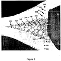
- Figure 3 is a photo showing a cross section of a joint on which hardness tests have been carried out.
- the average hardness is calculated as a numeric average and depends on the number of tests.
- braze-filler material was approximately 16 to 20g per 4 brazing points.
- a nickel based braze filler BNi-5 according to AWS A5.8 AMS specifications for braze-fillers was compared to iron-based braze-filler comprising 56 wt% Fe, 17 wt% Cr, 12 wt% Ni, 12 wt% Si, and 1 wt% B.
- the braze filler were applied to the test samples having 0.3-0.4 mm crevices, and the samples were heated in a furnace to a temperature of about 1200°C in a non-oxidative atmosphere.
- Table 1 Sample [g] Ni-based BNi-5 [N/mm 2 ] Iron-based [N/mm 2 ] 16 109 123 18 110 126 20 106 151
- the iron based braze-filler not only have the capability of filling large crevices but also have a very high mechanical strength at large crevices, making them suitable for brazing for example large heat exchangers or planar surfaces of for example reactor plates. Tests were performed by comparing amount of braze filler to tensile strength, the results are summarised in Table 2.
- Table 2 Sample [g] Iron based (invention) [N/mm 2 ] 25 162 55 227
- Hardness tests were made in a joint at an equally seal gap between two plates of base material (type 316). The tests were performed on an equal distance from the base material, in the centre of the joint.
- Hardness measurements HV1 were performed according to ASTM E92-82 (Standard test method for Vickers Hardness of Metallic Materials) and EN ISO 6507-1 (Metallic materials - Vickers hardness test- Part 1: Test method (ISO 6507-1:1997), and a comparison was made between a joint of BNi-5 and a joint of Fe-based material 56 wt% Fe, 17 wt% Cr, 12 wt% Ni, 12 wt% Si, and 1 wt% B.
- BNi-5 joint is harder than the Fe-based material joint.
- BNi-5 joint shows less ductility and consequently lower strength than the iron-based filler joint according to the invention, which is illustrated by lower hardness values of the iron-based filler joint.
- BNi-5 joint is brittle compared to the iron-based filler joint.
- Hardness tests were preformed on a large joint sealed with Fe-based filler comprising 56 wt% Fe, 17 wt% Cr, 12 wt% Ni, 12 wt% Si, and 1 wt% B. The tests were performed where the brazed joint has sealed a gap larger than 1000 ⁇ m, and the positions where the tests were done as in Figure 3 , but the photo in Figure 3 is not a photo of the joint in this Example. The results are 349 HV1, 336 HV1, 210 HV1, 197 HV1, 250 HV1, 300 HV1, and 287 HV1, which gives average hardness of 275 HV1.
- Test A The furnace was heated from 1100°C to 1200°C for 5 minutes, and then the heat was lowered to 1100°C for approximately 30 minutes.
- Test B The furnace was heated from 1100°C to 1200°C for 15 minutes, and then the heat was lowered to 1100°C for approximately 30 minutes.
- Test C The furnace was heated from 1100°C to 1200°C for 30 minutes, and then the heat was lowered to 1100°C for approximately 30 minutes.
- Test D The furnace was heated from 1100°C to 1200°C for 60 minutes, and then the heat was lowered to 1100°C for approximately 30 minutes.
- the plate packs were cut into sections to be analysed if the iron-based filler in the centre part of the plate pack had melted or not.
- the tested parts were optically investigated.
Description
- The present invention relates to a method of brazing articles of stainless steel according to the preamble of claim 1 (see, for example,
US 2004/056074 ). - Sealing of crevices and pores, and brazing of joints are important factors when producing brazed articles, especially when producing fluid tight articles without leakage. When the joints, crevices and pores are large in area, then the ability of sealing and filling increases its importance for the braze filler, but ability to seal and fill is not necessary linked to strength of the brazed zone or area. Therefore, one requirement is to provide articles, which have enough strength for the indented purpose or use. Different methods for brazing are developed and are described for instance in
US 6,109,505 andUS 4,516,716 , which documents disclose brazing of stainless steel. - Another requirement for the present invention is to provide brazed articles of stainless steel.
- Another requirement is to provide an improved method of brazing articles of stainless steel having large pores, cracks, joints, gaps, or crevices.
- In accordance with this invention there is provided a method as defined in the appended claims. Average hardness HV1 refers to (Vickers hardness test - Part 1: Test method (ISO 6507-1:1997)
- The brazed areas of the brazed article can have a tensile strength of at least 110 N/mm2.
- Even though the thermal expansion coefficient is the same for a small object and a large object of the same material, the larger object will have a larger total expansion. If one of two objects, with the same length at the same temperature, is heated, the difference in length will be proportional to the size of the object for the same difference in temperature. Both of those facts give rise to larger crevices, which brazing filler materials have to be able to fill. Thus, large size, i.e. area, length, broadness, thickness etc. of a metal object, has an effect on accuracy of brazed joints or brazed areas, since thermal expansion of the parts will differ, and may give rise to uneven fitness and large crevices. Other cases of uneven fitness may be caused by design of parts to be assembled, to movements when brazing the objects, or by manufacture of parts to be assembled. Therefore, one important aspect when brazing joints or areas etc. is the capability to fill and seal when brazing.
- Copper (Cu) has good capability to seal large crevices. One of the reasons for not using Cu brazed objects is the limitation of the properties of the Cu braze-filler, e.g. Cu can induce different types of corrosion problems. The most obvious problem is that copper is consumed due to corrosion. The consummation of copper can decrease the mechanical strength of the object and the object can begin to leak. The release of Cu corrosion products and Cu-ions into the media in an object can give rise to galvanic corrosion in other parts of the same system where the object is installed. Silver braze-filler might be an option, but are normally not used since the price for silver is high.
- Nickel (Ni) braze-fillers containing chromium (Cr) have better corrosion resistance than Cu braze-fillers, but Ni braze-fillers have some disadvantages. One of those is that nickel can be released from the nickel braze when used in e.g. water applications. The amount of nickel in e.g. tap water is limited by legislations. Ni-ions can also give rise to galvanic corrosion in other parts of the same system where the object is installed.
- An important issue for the strength is how large crevices or gaps the brazing filler material is able to fill. The capability of nickel braze-fillers to fill crevices is limited and nickel brazing materials can also lose strength in large crevices i.e. crevices larger than 0.076mm, see for instance ASM Handbook, Volume 6, Welding, Brazing and Soldering, first printing 1993/ Brazing of stainless steel page 911-913. Thus, large Ni-brazed objects are therefore very hard to produce.
- The selection of particular brazing filler metal for a specific application depends on variety of factors. Basic considerations are temperature and materials to be brazed. In any brazing process the brazing filler material must possess a solidus temperature that is high enough to provide the required properties to the brazed assembly. The process needs a liquidus temperature, which is low enough to be compatible with the temperature capabilities of the parts to be joined. The method of the present invention can be used for producing articles of stainless steel by brazing a base material of stainless steel with an alloy having mainly the same composition as the base material, thus providing a homogenized joint of the alloy between the base material or base materials. The brazing alloy comprises iron as the main component, and is an iron-based brazing filler material. The iron-based brazing filler material can be produced by gas-or water atomization, by melt spinning, mechanical alloying or by crushing of ingots.
- When brazing a joint it is suitable that the brazing material wets parts of the objects, which are to be brazed together, and that the brazing material can flow into crevices, joints, pores etc. during brazing. The melting point of the brazing filler material is suitable below the melting point of the base material of the parts. A relevant property of the brazing filler material is the capability to fill crevices, joints, pores etc. The nickel-based brazing materials have inferior capability of filling crevices, thus large size objects such as large Ni-brazed heat exchangers are very hard to produce.
- The brazing material can be manufactured as a sheet, a powder, or a powder mixed with a binder forming a paste, or the brazing material may be dispersed in a mixture of binder and liquid, which can be painted or sprayed on a surface of base material.
- The iron-based brazing filler material may be applied as a powder or as a paste one way may be to apply strings or drops of iron-based brazing filler material by pressing it through a nozzle. Another way of applying the iron-based brazing filler material may be to apply a binder in form of drops or strings on the base material and then scatter brazing powder over the surface.
- The brazed article may be a sub-assembled part that is brazed with one or more additional parts, the iron-based brazing filler material then being applied to the parts to be further brased, and after assembling the parts to be further brazed the steps of preheating the assembled parts and heating the assembled parts to the brazing temperature are repeated. This enables the manufacture of articles having a complex design, which have to be brazed in a stepwise fashion.
- A method additionally described includes heating to a brazing temperature of at least 1100°C, and in some examples heating to a brazing temperature of at least 1150°C. The heating may be carried out for at least 30 minutes. The parts or articles may be heated to the temperature at which the brazing material melts. The additionally described method comprises a step which includes preheating the parts to for example a temperature at least 400°C, at least 500°C or even at least 550°C and leaving the parts at that temperature for example at least 15 minutes, at least 30 minutes, at least 1 hour, or even longer, then raising the temperature to for example at least 900°C, at least 1000°C or even at least 1100°C the parts are left at so this temperature to equalise the temperature in the parts so that the temperature is equal all through the parts and brazing material. The time to equalise depends on size of the article to be brazed; for smaller objects shorter time may be sufficient. Suitable times may be for example at least one hour, at least 2 hours, at least 3 hours, or even longer times. The temperature depends on the liquidus - solidus temperature of the brazing material and the composition of the brazing alloy and the melting point lowering elements. After equalising the temperature in the parts to be brazed the temperature is raised to a brazing temperature. Both brazing time and brazing temperature depends on brazing material but also on the size and shape of the article to be brazed. The brazing may be divided into A) melting the brazing material, B) flowing the brazing material by capillary force between adjacent surfaces and setting the melted brazing material, and C) diffuse the elements of the brazing material with the base material or alloy of the parts to be brazed.
- During the brazing process, the brazing material diffuses with the adjacent surfaces so that they and the brazing material together constitute a partly homogeneous material region.
- If the temperature in the middle of the article is not high enough the middle part will not be brazed because the brazing material will not melt, and the properties of the article will be inferior.
- Examples of brazing times and temperature are: heating to at least 1100°C and heating for at least 30 minutes; heating to at least 1100°C and heating for at least 45 minutes; and heating to at least 1100°C for more than 60 minutes. According to a further alternative the temperature may be at least 1150°C and the time may be at least 25 minutes
- A large heat exchanger may have several plates stacked together. The plate pack may comprise 10, 20, or more plates. A heat exchanger may have 100, 150, 200 or more plates. A large heat exchanger may be defined by the area of the heat exchanger plates and another way of defining a big heat exchanger is the number of plates.
- During the brazing process, the brazing material diffuses with the adjacent surfaces so that they and the brazing material together constitute a partly homogeneous material region.
- To braze together planar surfaces and form tight joints may be hard to achieve by conventional methods. The present invention provides a method for brazing together two planar surfaces by using an iron-based brazing material containing melting point reducer in such a way that the brazing material's capillary-induced positioning between the surfaces can be controlled. The iron based brazing filler material may be applied to planar surfaces or to large surfaces by the aid of capillary force breakers. The capillary force breakers can be in form of grooves, traces, paths, passages, v or u shaped tracks or pathways etc. or in form of nets etc. The iron-based brazing filler material may be applied into the capillary force breakers, i.e. into the grooves, traces, paths, passages, v or u shaped tracks, pathways, nets etc., or the brazing filler material may be applied close to the capillary force breakers. During heating the applied iron-based brazing filler material will flow to the area where the capillary force may be broken and braze together the surfaces, which are adjacent to each other. Thus, the brazed area provides brazed, sealed or tight cervices, joints etc. between planar surface where it is hard otherwise to braze uniformly. The capillary force breakers enable also brazing of surfaces having large crevices, parts having odd shape, etc.
- When the brazing material is applied between two parts close to a capillary force breaker the flowing viscous brazing material will stop the flowing motion and set at the rim of the capillary force breaker. A reactor channel may be functioning as a capillary force breaker. A plate having a reactor channel is applied with brazing material and a barrier plate or the like is placed in contact with the reactor channel plate. The flowing brazing material will stop and set at boarder of the reactor channel, which will seal the reactor plate against the barrier plate without filling the reactor channel with set brazing material.
- How far the brazing material can flow between two bordering surfaces depends partly on the brazing materials setting time and the distance between the surfaces, and the amount of brazing material. Since the brazing material "sticks" to each surface, which is to be brazed, the intermediate space between the surfaces becomes smaller. As the intermediate space becomes smaller while at the same time the brazing material sets, it also becomes more difficult for the brazing material to flow in between.
- in the method of the invention the brazing takes place in presence of inert gas or active shielding gas. The heating or brazing may be carried out in presence of one or more of the gases selected from the group consisting of helium, argon, nitrogen, hydrogen, carbon dioxide, or one or more of the mentioned gases in combinations with vacuum.
- According to the method of the present invention the formed brazing zones or brazing areas, such as for example brazed joints, pores, cracks, gaps, crevices etc. have an average hardness of less than 600 HV1. The brazing zones or brazing areas may have average hardness of less than 500 HV1, less than 400 HV1, less than 350 HV1, and possibly less than 300 HV1.
- Since the iron-based brazing filler materials have flow properties and wetting properties to penetrate into crevices, the iron-based brazing filler materials will create a bonding to the base material, seal crevices, and be able to join planar surfaces by brazing. According to one alternative aspect of the invention the iron-based brazing filler materials can seal or fill pores, cracks, gaps, joints, or crevices larger than as large as 1000 µm, and may seal or fill pores, cracks, gaps, joints, or crevices up to 3000 µm or more. According to the method of the present invention pores, cracks, gaps, joints, or crevices larger than 250 µm are sealed or filled by the iron-based brazing filler material and the provided brazed zone or brazed area has an average hardness of less than 350 HV1. According to another alternative aspect of the method may pores, cracks, gaps, joints, or crevices larger than 1000 µm may be sealed or filled by the iron-based brazing filler material and the provided brazed zone or brazed area having average hardness of less than 350 HV1.
- The desired amount of brazing material is supplied to the contact points, which are to be brazed together in any of the described or other ways. The brazing material may cover an area that is somewhat larger than the contact joint point. The contact joint points may have a diameter of at least 0.5 mm.
- Suitable iron-based brazing filler materials are disclosed in
WO 02/38327 WO 02/098600 US 3,736,128 ,US 4,402,742 ,US 4,410,604 ,US 4,516,716 ,US 6,656,292 , orEP 0 418 606 . According to one aspect of the present method may the iron-based brazing filler materials be selected from the materials disclosed inWO 02/38327 WO 02/098600 - Since the brazing process is a metallic process and the respective surfaces for brazing take the form of metallic material, then iron-based brazing material during the brazing process diffuses with bordering surfaces, which are to be brazed together. The joint or seam between the two joined surfaces will more or less "disappear" during the brazing process according to one aspect of the invention. The brazed seam together with the surfaces of the metallic parts will become a unity with only small changes in material composition of the alloys.
- When the parts are heat exchanger plates, the plates can be endplates, adaptor plates, sealing plates, frame plates etc., and constitute a heat exchanger system. Each of the heat exchanger plates comprise at least one port recess, which port recesses together form part of a port channel when the plates are placed on one another. The plates are stacked together in a plate stack or a plate pack in the heat exchanger. The plate package comprises between the plates a number of channels, which accommodate a number of media. The media in adjacent channels are subject to temperature transfer through the heat transfer plate in a conventional manner. The plates may comprise an edge, which may partly extend down and over the edge portion of an adjacent heat transfer plate in the plate stack. The edges of the plates seal against the adjacent heat transfer plate in such a way that a channel may be formed between the plates. This channel either allows flow of a medium or is closed so that no flow takes place and the channel is therefore empty. To stiffen the plate package and the port regions, an adaptor plate or an endplate may be fitted to the package. The surfaces of the endplate or the adaptor plate are with may be planar so that contact surfaces between the surfaces may be maximised. As previously mentioned, the respective port recesses on the plates coincide, thereby forming a channel. On the inside of this port channel there is therefore a joint between the two plates. To prevent leakage at this joint brazing material may be applied round the port region between the plates. The brazing material may be placed in or close by a capillary force breaker, which may extend wholly or partly round the port region between the plates. In the plate package brazing material may be applied on different pre-designed or predetermined parts of the plates. During the brazing process, the brazing material will become viscous and will flow from the applied parts out between the plates due to the action of capillary force. The advantage of applying brazing material on to predetermined places makes it possible to control volume and amount of the brazing material, and to control which parts of the surfaces to be brazed and which are not. When brazing a heat exchanger at least three heat exchanger plates are needed, but it is usual that several plates are brazed together. According to one alternative aspect of the invention are a plate pack of several plates brazed together at the same time in the same oven.
- The brazing method of the invention may either comprise brazing the article assembled with all its parts at the same time or may the article be brazed in a stepwise fashion where parts are first assembled and brazed together, and then assembled with further parts and brazed together, and so on using the same type of brazing material in each brazing cycle.
- Further features and embodiments of the invention are defined by the sub-claims.
- In the following the present invention will be explained in more detail by means of the attached photos.
-
- Figure 1
- is a photo showing a cross section of a part of a heat exchanger.
- Figure 2
- is a schematic drawing showing a cross section of a joint.
- Figure 3
- is a photo showing a cross section of a joint on which hardness tests are carried out.
-
Figure 1 is showing that the iron-based brazing filler material is able to fill large cervices, and that it is possible to braze with large quantities of brazing material. The large heat exchangers braze joints are therefore characterized in that there is lot of braze filler applied and also that large homogenisation zones are found. A part of the braze filler and part of the original plate thickness have been mixed into the homogenisation zone. -
Figure 2 is schematically showing relationships between different parameters in a brazed crevice or joint, brazed by filler material F. Letter A represent plate thickness of plate E which also represent base material E. B represent the smallest thickness of a brazed crevice or joint between base material E or plates E, C represent the largest thickness of a brazed crevice or joint without any pores, cracks or passages, and letter D represent the largest thickness of a brazed crevice or joint where any pores, cracks or passages G opens up to but is still sealed. If there is no trace of any pores, cracks or passages then C = D. For nickel based filler material C = D is less than C = D for iron based filler material. The presences of pores, cracks or passages make the brazed zone less strong. -
Figure 3 is a photo showing a cross section of a joint on which hardness tests have been carried out. The average hardness is calculated as a numeric average and depends on the number of tests. - Some aspects are now illustrated in the Examples. If not otherwise stated in the examples and tables the percentage is given by weight (wt%). Examples 1 to 5 do not illustrate aspects failing under the scope of claim 1.
- Test samples having geometry similar to the plate pattern inside brazed thin walled pressed heat exchanger plates were tested. The applied amount of braze-filler material was approximately 16 to 20g per 4 brazing points. A nickel based braze filler BNi-5 according to AWS A5.8 AMS specifications for braze-fillers was compared to iron-based braze-filler comprising 56 wt% Fe, 17 wt% Cr, 12 wt% Ni, 12 wt% Si, and 1 wt% B. The braze filler were applied to the test samples having 0.3-0.4 mm crevices, and the samples were heated in a furnace to a temperature of about 1200°C in a non-oxidative atmosphere. The test results are summarised in Table 1.
Table 1 Sample [g] Ni-based BNi-5 [N/mm2] Iron-based [N/mm2] 16 109 123 18 110 126 20 106 151 - The test results show that the Fe-based braze-filler, both can fill crevices that are large see
Figure 1 , and can obtain very good strength at the same time compared to Ni-based braze-fillers. Even at the test amount, it can be seen that the Fe-braze has the best mechanical strength of the tested fillers.Figure 1 shows a cross-section of a Fe-based brazed heat exchanger. In the picture, it can be seen that crevices between 0.4-0.6 mm are tightened. - Now it has been found that the iron based braze-filler not only have the capability of filling large crevices but also have a very high mechanical strength at large crevices, making them suitable for brazing for example large heat exchangers or planar surfaces of for example reactor plates. Tests were performed by comparing amount of braze filler to tensile strength, the results are summarised in Table 2.
Table 2 Sample [g] Iron based (invention) [N/mm2] 25 162 55 227 - A series of test was performed by changing the heat treatment cycle of the brazening process to obtain as good filling as possible. A significant difference was discovered, even at very short heat treatment cycle (5minutes), very good filling was obtained with the Fe-based filler. The brazing tests were carried out at 1100°C comparing the ability to fill crevices between a nickel based filler (BNi-5) and an iron based filler comprising 56 wt% Fe, 17 wt% Cr, 12 wt% Ni, 12 wt% Si, and 1 wt% B. The results are summarized in Table 3.
Table 3 Time [minutes] C Figure 2 BNi-5 [µm]C Figure 2 iron-based filler [µm]5 130 800-1200 15 180 800-1200 30 220 800-1200 150 300 800-1200 - The test results show that BNi-5 needs a long heat treatment to braze larger joints, but even after long heat treatment times BNi-5 did not fill crevices as good as the iron-based filler. The iron-based filler filled larger crevices in very short time compared to BNi-5. The longer brazing times for BNi-5 are therefore more energy consuming than those for the iron based filler.
- The hardness tests were made in a joint at an equally seal gap between two plates of base material (type 316). The tests were performed on an equal distance from the base material, in the centre of the joint. Hardness measurements HV1 were performed according to ASTM E92-82 (Standard test method for Vickers Hardness of Metallic Materials) and EN ISO 6507-1 (Metallic materials - Vickers hardness test- Part 1: Test method (ISO 6507-1:1997), and a comparison was made between a joint of BNi-5 and a joint of Fe-based material 56 wt% Fe, 17 wt% Cr, 12 wt% Ni, 12 wt% Si, and 1 wt% B. The results are summarised in Table 4.
Table 4 Joint made with BNi-5 [HV1] Joint made with Fe-based material [HV1] 490 260 600 210 520 280 480 270 - The hardness test results show that BNi-5 joint is harder than the Fe-based material joint. Thus, BNi-5 joint shows less ductility and consequently lower strength than the iron-based filler joint according to the invention, which is illustrated by lower hardness values of the iron-based filler joint. Thus, BNi-5 joint is brittle compared to the iron-based filler joint.
- Hardness tests were preformed on a large joint sealed with Fe-based filler comprising 56 wt% Fe, 17 wt% Cr, 12 wt% Ni, 12 wt% Si, and 1 wt% B. The tests were performed where the brazed joint has sealed a gap larger than 1000 µm, and the positions where the tests were done as in
Figure 3 , but the photo inFigure 3 is not a photo of the joint in this Example. The results are 349 HV1, 336 HV1, 210 HV1, 197 HV1, 250 HV1, 300 HV1, and 287 HV1, which gives average hardness of 275 HV1. - In this example tests were carried out to produce a heat exchanger without leakage, i.e. which is fully brazed without defaulting joints. An iron-based filler defined in
WO 02/38327 - In all tests of the heat treatment cycles the heat exchange plate pack was first heated to 500°C for 1 hour, then the temperature was raised to 1100°C for 4 hours to ensure heating of the whole plate pack.
- Test A: The furnace was heated from 1100°C to 1200°C for 5 minutes, and then the heat was lowered to 1100°C for approximately 30 minutes.
- Test B: The furnace was heated from 1100°C to 1200°C for 15 minutes, and then the heat was lowered to 1100°C for approximately 30 minutes.
- Test C: The furnace was heated from 1100°C to 1200°C for 30 minutes, and then the heat was lowered to 1100°C for approximately 30 minutes.
- Test D: The furnace was heated from 1100°C to 1200°C for 60 minutes, and then the heat was lowered to 1100°C for approximately 30 minutes.
- Analysis: The plate packs were cut into sections to be analysed if the iron-based filler in the centre part of the plate pack had melted or not. The tested parts were optically investigated.
-
- Test A: Filler in the centre not melted.
- Test B: Filler in the centre not melted.
- Test C: Filler in the centre partly melted (more sintered).
- Test D: Filler in the centre melted.
Claims (5)
- A method of brazing an article of stainless steel comprising stainless steel parts, wherein the article is a heat exchanger plate pack, the method comprising:applying an iron-based brazing filler material to the parts of stainless steel to be brazed and assembling the parts together, the iron-based brazing filler material comprising at least 40 wt% Fe, 14-21 wt% Cr, 5-21 wt% Ni, 0-8 wt% Mn, 0-2 wt% C and 0-15 wt% Hf and either 6-15 wt% Si and 0.2-1.5 wt% B, or 4-9 wt% Si and 4-9 wt% P, characterized by:preheating the assembled parts in a non-oxidising atmosphere, a reducing atmosphere, vacuum or combinations thereof, to at least 500°C and leaving the parts at the temperature of at least 500°C for at least 15 minutes, raising the temperature to at least 100°C and leaving the parts at the temperature of at least 100°C for at least one hour to equalise the temperature of the parts so that the temperature is equal through the parts and the brazing material, the assembled parts then being heated to a brazing temperature of at least 1200°C for at least 30 minutes to braze the parts and so that the brazing material melts in the centre of the plate pack and flows into joints, pores, cracks, gaps or crevices to be filled or sealed, lowering the heat to 1100°C for approximately 30 minutes; andallowing the brazing material to set thereby to form in the brazed article brazed areas having an average hardness less than 600 HV1,wherein joints, pores, cracks, gaps or crevices larger than 250 µm, or combinations thereof, are sealed or filled by the brazing material, and the brazed areas have an average hardness of less than 350 HV1 measured at or close to a centre line of the brazed area.
- A method according to claim 1, wherein the iron-based brazing material is obtained by gas atomization, by water atomization, or by crushing of ingots, and the iron-based brazing material is applied to the stainless steel parts as a paste in strings or in drops.
- A method according to any one of the preceding claims, wherein the brazed areas of the brazed article have a tensile strength of at least 110 N/mm2.
- A method according to any one of the preceding claims, wherein the heat exchanger has a plate pack of more than 9 heat exchanger plates brazed together.
- A method according to claim 2, wherein the iron-based brazing material is applied with aid of capillary force breakers in form of grooves, paths, traces, passages, v- or u- shaped tracks, pathways, nets, or combinations thereof, on stainless steel to be brazed.
Priority Applications (5)
| Application Number | Priority Date | Filing Date | Title |
|---|---|---|---|
| SI200631804T SI1888294T1 (en) | 2005-05-26 | 2006-05-24 | A method of brazing articles of stainless steel |
| DK12152118.1T DK2446996T3 (en) | 2005-05-26 | 2006-05-24 | STAINLESS STEEL HEAT EXCHANGE OF STAINLESS STEEL WITH STAINLESS STEEL HEADWARE MATERIAL |
| PL06747812T PL1888294T5 (en) | 2005-05-26 | 2006-05-24 | A method of brazing articles of stainless steel |
| EP12152118.1A EP2446996B1 (en) | 2005-05-26 | 2006-05-24 | Brazed plate heat exchanger of stainless steel with stainless steel brazing material |
| PL12152118T PL2446996T3 (en) | 2005-05-26 | 2006-05-24 | Brazed plate heat exchanger of stainless steel with stainless steel brazing material |
Applications Claiming Priority (3)
| Application Number | Priority Date | Filing Date | Title |
|---|---|---|---|
| SE0501198A SE531092C2 (en) | 2005-05-26 | 2005-05-26 | Method for joining two surfaces together and a device comprising two jointed surfaces |
| SE0501199A SE529913C2 (en) | 2005-05-26 | 2005-05-26 | Brazing articles of stainless steel, e.g. large heat exchanger involves applying an iron-based brazing filler material to parts of stainless steel, heating the parts, and providing brazed areas with specific average hardness |
| PCT/SE2006/000618 WO2006126953A1 (en) | 2005-05-26 | 2006-05-24 | A method of brazing articles of stainless steel |
Related Child Applications (2)
| Application Number | Title | Priority Date | Filing Date |
|---|---|---|---|
| EP12152118.1A Division-Into EP2446996B1 (en) | 2005-05-26 | 2006-05-24 | Brazed plate heat exchanger of stainless steel with stainless steel brazing material |
| EP12152118.1A Division EP2446996B1 (en) | 2005-05-26 | 2006-05-24 | Brazed plate heat exchanger of stainless steel with stainless steel brazing material |
Publications (4)
| Publication Number | Publication Date |
|---|---|
| EP1888294A1 EP1888294A1 (en) | 2008-02-20 |
| EP1888294B1 EP1888294B1 (en) | 2014-05-07 |
| EP1888294B2 true EP1888294B2 (en) | 2017-01-25 |
| EP1888294B9 EP1888294B9 (en) | 2017-04-12 |
Family
ID=37452285
Family Applications (2)
| Application Number | Title | Priority Date | Filing Date |
|---|---|---|---|
| EP12152118.1A Active EP2446996B1 (en) | 2005-05-26 | 2006-05-24 | Brazed plate heat exchanger of stainless steel with stainless steel brazing material |
| EP06747812.3A Active EP1888294B9 (en) | 2005-05-26 | 2006-05-24 | A method of brazing articles of stainless steel |
Family Applications Before (1)
| Application Number | Title | Priority Date | Filing Date |
|---|---|---|---|
| EP12152118.1A Active EP2446996B1 (en) | 2005-05-26 | 2006-05-24 | Brazed plate heat exchanger of stainless steel with stainless steel brazing material |
Country Status (10)
| Country | Link |
|---|---|
| US (2) | US8857699B2 (en) |
| EP (2) | EP2446996B1 (en) |
| JP (2) | JP5215174B2 (en) |
| KR (1) | KR101329941B1 (en) |
| DK (2) | DK2446996T3 (en) |
| ES (1) | ES2483968T5 (en) |
| PL (2) | PL1888294T5 (en) |
| PT (1) | PT1888294E (en) |
| SI (1) | SI1888294T1 (en) |
| WO (1) | WO2006126953A1 (en) |
Families Citing this family (25)
| Publication number | Priority date | Publication date | Assignee | Title |
|---|---|---|---|---|
| SE523855C2 (en) | 2000-11-10 | 2004-05-25 | Alfa Laval Corp Ab | Iron-based brazing material for joining elm and soldered product made herewith |
| US8894780B2 (en) | 2006-09-13 | 2014-11-25 | Vacuumschmelze Gmbh & Co. Kg | Nickel/iron-based braze and process for brazing |
| SE531988C2 (en) * | 2006-11-17 | 2009-09-22 | Alfa Laval Corp Ab | Soldering material and method of soldering with this material |
| DE102007028275A1 (en) * | 2007-06-15 | 2008-12-18 | Vacuumschmelze Gmbh & Co. Kg | Brazing foil on an iron basis as well as methods for brazing |
| WO2009128174A1 (en) * | 2008-04-18 | 2009-10-22 | 福田金属箔粉工業株式会社 | Iron-base heat- and corrosion-resistant brazing filler metals |
| JP5212401B2 (en) * | 2009-05-11 | 2013-06-19 | 新日鐵住金株式会社 | Bonding alloy |
| JP5546836B2 (en) * | 2009-11-26 | 2014-07-09 | 山陽特殊製鋼株式会社 | Ni-Fe base alloy brazing material |
| BR112014005075A2 (en) * | 2011-09-05 | 2017-03-28 | Basf Corp | methods for applying a brazing material to a metal honeycomb matrix and for fabricating a metal honeycomb matrix, and metal honeycomb matrix |
| EP2574420B1 (en) | 2011-09-29 | 2014-10-22 | Alfa Laval Corporate AB | Iron-based brazing composition and method of joining heat transfer plates |
| DK2644312T3 (en) * | 2012-03-28 | 2019-02-25 | Alfa Laval Corp Ab | Hitherto unknown soldering concept |
| WO2014008537A1 (en) * | 2012-07-09 | 2014-01-16 | Hugget Paul | Brazing method and composites produced thereby |
| ES2756850T3 (en) | 2013-09-26 | 2020-04-27 | Alfa Laval Corp Ab | Method of joining metal parts using a melting point depressant layer |
| EP2853332A1 (en) * | 2013-09-26 | 2015-04-01 | Alfa Laval Corporate AB | A novel brazing concept |
| KR101818964B1 (en) | 2015-07-24 | 2018-01-17 | 덕산하이메탈(주) | Low temperature bonding method using brazing alloys with exothermic and amorphous characteristics for low temperature bonding |
| JP6042956B1 (en) * | 2015-09-30 | 2016-12-14 | オリジン電気株式会社 | Method for manufacturing soldered products |
| KR101874559B1 (en) * | 2016-12-07 | 2018-08-02 | 동양피스톤 주식회사 | Piston for vehicle engine and method for manufacturing the same |
| DE102016124206A1 (en) * | 2016-12-13 | 2018-06-14 | Michael Rehberg | Plate heat exchanger manufacturing process and plate heat exchanger |
| DE112018003831T5 (en) | 2017-07-28 | 2020-04-09 | Dana Canada Corporation | ULTRA-THIN HEAT EXCHANGER FOR HEAT MANAGEMENT |
| CN110891729B (en) | 2017-07-28 | 2022-04-19 | 达纳加拿大公司 | Apparatus and method for aligning components for laser welding |
| KR102064200B1 (en) * | 2019-05-09 | 2020-01-09 | 천성민 | Plate Heat Exchanger Assembly and Manufacturing Method for Plate Type Heat Exchanger |
| US11298768B2 (en) | 2019-11-15 | 2022-04-12 | Rolls-Royce Corporation | Method of preparing a surface for diffusion bonding and method of diffusion bonding |
| US11571762B2 (en) * | 2019-11-15 | 2023-02-07 | Rolls-Royce North American Technologies Inc. | Printing method to selectively deposit braze powders at one or more predetermined locations on a surface |
| US11565336B2 (en) | 2019-11-15 | 2023-01-31 | Rolls-Royce North American Technologies Inc. | Method of selectively bonding braze powders to a surface |
| US11420279B2 (en) | 2019-11-15 | 2022-08-23 | Rolls-Royce Corporation | Method of selectively bonding braze powders to a surface |
| US20230038008A1 (en) | 2021-07-26 | 2023-02-09 | Vacuumschmelze Gmbh & Co. Kg | Brazing foil, object and method for brazing |
Citations (2)
| Publication number | Priority date | Publication date | Assignee | Title |
|---|---|---|---|---|
| WO2002038327A1 (en) † | 2000-11-10 | 2002-05-16 | Alfa Laval Corporate Ab | Material for joining and product produced therewith |
| WO2002098600A1 (en) † | 2001-06-05 | 2002-12-12 | Alfa Laval Corporate Ab | Brazing material and brazed product manufactured therewith |
Family Cites Families (30)
| Publication number | Priority date | Publication date | Assignee | Title |
|---|---|---|---|---|
| GB797800A (en) | 1956-04-24 | 1958-07-09 | Coast Metals Inc | Brazing alloys |
| US2843478A (en) * | 1957-10-28 | 1958-07-15 | Ronald R Cost | High temperature brazing alloy for joining fe cr al materials and austenitic and ferritic stainless steels |
| US3736128A (en) | 1971-06-04 | 1973-05-29 | Pechiney Ugine Kuhlmann | Stainless steel with a high boron content |
| US4402742A (en) * | 1981-10-29 | 1983-09-06 | Get Products Corporation | Iron-nickel base brazing filler metal |
| US4410604A (en) * | 1981-11-16 | 1983-10-18 | The Garrett Corporation | Iron-based brazing alloy compositions and brazed assemblies with iron based brazing alloys |
| US4516716A (en) * | 1982-11-18 | 1985-05-14 | Gte Products Corporation | Method of brazing with iron-based and hard surfacing alloys |
| JPS59101244A (en) | 1982-11-30 | 1984-06-11 | Tsuchiya Mfg Co Ltd | Manufacture of metallic honeycomb body |
| JPS59101233A (en) | 1982-11-30 | 1984-06-11 | Mitsui Eng & Shipbuild Co Ltd | Automatic bar steel bending device |
| JPS62234655A (en) * | 1986-04-02 | 1987-10-14 | Hitachi Ltd | Repairing method for airtight structure |
| JPH0667551B2 (en) * | 1987-05-13 | 1994-08-31 | 三菱重工業株式会社 | Manufacturing method of laminated heat-resistant alloy sheet |
| EP0437626B1 (en) * | 1989-08-04 | 1994-12-28 | Showa Aircraft Industry Co., Ltd. | Heat resistant structure and method of manufacture thereof |
| NO179483C (en) | 1989-08-29 | 1996-10-16 | Sumitomo Metal Ind | Process for establishing diffusion bonding between corrosion resistant materials |
| JPH0715665Y2 (en) * | 1991-02-01 | 1995-04-12 | 小島プレス工業株式会社 | Joining structure of metal members |
| US6200690B1 (en) * | 1995-05-22 | 2001-03-13 | Alliedsignal Inc. | Nickel-chromium-based brazing alloys |
| US6149051A (en) * | 1997-08-07 | 2000-11-21 | Alliedsignal Inc. | Braze titanium |
| FR2781399B1 (en) | 1998-07-23 | 2000-08-18 | Sochata Energy 1 Soc | METHOD OF BRAZING-DIFFUSING SUPERALLOY PARTS |
| SE513784C2 (en) * | 1999-03-09 | 2000-11-06 | Alfa Laval Ab | Permanently joined plate heat exchanger |
| KR100656636B1 (en) | 1999-11-22 | 2006-12-11 | 에지스 지오기스제르기아르 엔와이알티. | Process for the preparation of 6-methyl-2-4-methyl-phenyl-imidazo[1,2-a]pyridine-3-n,n-dimethyl-acetamide and intermediates |
| JP4288821B2 (en) * | 2000-02-28 | 2009-07-01 | 日立金属株式会社 | Low thermal expansion Fe-based heat-resistant alloy with excellent high-temperature strength |
| DE10053000A1 (en) * | 2000-10-25 | 2002-05-08 | Eaton Fluid Power Gmbh | Air conditioning system with internal heat exchanger and heat exchanger tube for one |
| CN1246118C (en) * | 2000-12-28 | 2006-03-22 | 布拉景有限公司 | Plate type heat exchanger and method for manufacture thereof |
| SE519062C2 (en) * | 2001-05-03 | 2003-01-07 | Alfa Laval Corp Ab | Ways of soldering thin heat exchanger plates and soldered plate heat exchangers prepared according to the method |
| JP3848871B2 (en) * | 2001-11-30 | 2006-11-22 | 三菱重工業株式会社 | Brazing method using iron brazing material and iron brazing material |
| JP2003245713A (en) * | 2002-02-21 | 2003-09-02 | Usui Kokusai Sangyo Kaisha Ltd | Multiple wound super-ferritic stainless steel tube and method for manufacturing the same |
| US6656292B1 (en) * | 2002-06-13 | 2003-12-02 | Metzlas, Inc. | Iron-chromium base brazing filler metals |
| KR100487327B1 (en) * | 2002-09-25 | 2005-05-03 | 엘지전자 주식회사 | microwave oven range with toaster |
| DE10252577B4 (en) | 2002-11-12 | 2008-08-07 | Fraunhofer-Gesellschaft zur Förderung der angewandten Forschung e.V. | Method for producing a solder joint by capillary solder flow |
| SE527509C2 (en) | 2003-10-17 | 2006-03-28 | Alfa Laval Corp Ab | Soldered plate heat exchanger with plates of substantially stainless steel and process for manufacturing such plate heat exchanger |
| US20060090820A1 (en) * | 2004-11-01 | 2006-05-04 | Metglas, Inc. | Iron-based brazing filler metals |
| SE530011C2 (en) * | 2006-06-05 | 2008-02-05 | Alfa Laval Corp Ab | Heat exchanger plate and plate heat exchanger |
-
2006
- 2006-05-24 PT PT06747812T patent/PT1888294E/en unknown
- 2006-05-24 PL PL06747812T patent/PL1888294T5/en unknown
- 2006-05-24 PL PL12152118T patent/PL2446996T3/en unknown
- 2006-05-24 US US11/915,184 patent/US8857699B2/en active Active
- 2006-05-24 EP EP12152118.1A patent/EP2446996B1/en active Active
- 2006-05-24 ES ES06747812.3T patent/ES2483968T5/en active Active
- 2006-05-24 KR KR1020077030093A patent/KR101329941B1/en active IP Right Grant
- 2006-05-24 DK DK12152118.1T patent/DK2446996T3/en active
- 2006-05-24 WO PCT/SE2006/000618 patent/WO2006126953A1/en active Application Filing
- 2006-05-24 JP JP2008513417A patent/JP5215174B2/en active Active
- 2006-05-24 DK DK06747812.3T patent/DK1888294T4/en active
- 2006-05-24 SI SI200631804T patent/SI1888294T1/en unknown
- 2006-05-24 EP EP06747812.3A patent/EP1888294B9/en active Active
-
2012
- 2012-12-25 JP JP2012281095A patent/JP5469738B2/en active Active
-
2014
- 2014-09-10 US US14/482,729 patent/US20150053389A1/en not_active Abandoned
Patent Citations (2)
| Publication number | Priority date | Publication date | Assignee | Title |
|---|---|---|---|---|
| WO2002038327A1 (en) † | 2000-11-10 | 2002-05-16 | Alfa Laval Corporate Ab | Material for joining and product produced therewith |
| WO2002098600A1 (en) † | 2001-06-05 | 2002-12-12 | Alfa Laval Corporate Ab | Brazing material and brazed product manufactured therewith |
Non-Patent Citations (1)
| Title |
|---|
| SZCZUREK J. ET AL: "Proceeedings of the 3rd International Brazing conference, April 24-26, 2006", ISSUES IN VACUUM BRAZING, 24 April 2006 (2006-04-24), pages 326 - 333 † |
Also Published As
| Publication number | Publication date |
|---|---|
| PT1888294E (en) | 2014-07-28 |
| DK2446996T3 (en) | 2017-07-24 |
| WO2006126953A1 (en) | 2006-11-30 |
| US20080199718A1 (en) | 2008-08-21 |
| ES2483968T5 (en) | 2017-06-28 |
| PL1888294T5 (en) | 2017-10-31 |
| KR101329941B1 (en) | 2013-11-14 |
| JP2008542030A (en) | 2008-11-27 |
| EP1888294B9 (en) | 2017-04-12 |
| JP5215174B2 (en) | 2013-06-19 |
| EP1888294A1 (en) | 2008-02-20 |
| SI1888294T1 (en) | 2014-08-29 |
| EP2446996B1 (en) | 2017-04-26 |
| DK1888294T3 (en) | 2014-07-28 |
| DK1888294T4 (en) | 2017-05-01 |
| JP5469738B2 (en) | 2014-04-16 |
| PL2446996T3 (en) | 2017-10-31 |
| US20150053389A1 (en) | 2015-02-26 |
| US8857699B2 (en) | 2014-10-14 |
| KR20080015871A (en) | 2008-02-20 |
| ES2483968T3 (en) | 2014-08-08 |
| EP2446996A1 (en) | 2012-05-02 |
| JP2013099785A (en) | 2013-05-23 |
| EP1888294B1 (en) | 2014-05-07 |
| PL1888294T3 (en) | 2014-10-31 |
Similar Documents
| Publication | Publication Date | Title |
|---|---|---|
| EP1888294B2 (en) | A method of brazing articles of stainless steel | |
| US8287805B2 (en) | Brazing material | |
| EP2094431B1 (en) | Brazing material | |
| CN101184578B (en) | A method of brazing articles of stainless steel and stainless steel welded products obtained by the method | |
| EP1864749B1 (en) | Brazing filler material, composite material for brazing and brazed structure joined by using those | |
| US20160184935A1 (en) | Brazing material | |
| AU2014200267B2 (en) | Brazing material, a method of brazing, a brazed article and a paste comprising this brazing material |
Legal Events
| Date | Code | Title | Description |
|---|---|---|---|
| PUAI | Public reference made under article 153(3) epc to a published international application that has entered the european phase |
Free format text: ORIGINAL CODE: 0009012 |
|
| 17P | Request for examination filed |
Effective date: 20071211 |
|
| AK | Designated contracting states |
Kind code of ref document: A1 Designated state(s): AT BE BG CH CY CZ DE DK EE ES FI FR GB GR HU IE IS IT LI LT LU LV MC NL PL PT RO SE SI SK TR |
|
| DAX | Request for extension of the european patent (deleted) | ||
| RIC1 | Information provided on ipc code assigned before grant |
Ipc: B23K 1/19 20060101ALI20090415BHEP Ipc: B23K 35/30 20060101AFI20070119BHEP Ipc: B23K 1/008 20060101ALI20090415BHEP Ipc: B23K 1/00 20060101ALI20090415BHEP |
|
| 17Q | First examination report despatched |
Effective date: 20100125 |
|
| TPAC | Observations filed by third parties |
Free format text: ORIGINAL CODE: EPIDOSNTIPA |
|
| GRAP | Despatch of communication of intention to grant a patent |
Free format text: ORIGINAL CODE: EPIDOSNIGR1 |
|
| INTG | Intention to grant announced |
Effective date: 20140108 |
|
| GRAS | Grant fee paid |
Free format text: ORIGINAL CODE: EPIDOSNIGR3 |
|
| GRAA | (expected) grant |
Free format text: ORIGINAL CODE: 0009210 |
|
| AK | Designated contracting states |
Kind code of ref document: B1 Designated state(s): AT BE BG CH CY CZ DE DK EE ES FI FR GB GR HU IE IS IT LI LT LU LV MC NL PL PT RO SE SI SK TR |
|
| REG | Reference to a national code |
Ref country code: GB Ref legal event code: FG4D |
|
| REG | Reference to a national code |
Ref country code: AT Ref legal event code: REF Ref document number: 666208 Country of ref document: AT Kind code of ref document: T Effective date: 20140515 |
|
| REG | Reference to a national code |
Ref country code: IE Ref legal event code: FG4D |
|
| REG | Reference to a national code |
Ref country code: DE Ref legal event code: R096 Ref document number: 602006041472 Country of ref document: DE Effective date: 20140618 |
|
| REG | Reference to a national code |
Ref country code: SE Ref legal event code: TRGR |
|
| REG | Reference to a national code |
Ref country code: CH Ref legal event code: NV Representative=s name: MARKS AND CLERK (LUXEMBOURG) LLP, CH |
|
| REG | Reference to a national code |
Ref country code: DK Ref legal event code: T3 Effective date: 20140724 Ref country code: PT Ref legal event code: SC4A Free format text: AVAILABILITY OF NATIONAL TRANSLATION Effective date: 20140722 |
|
| REG | Reference to a national code |
Ref country code: ES Ref legal event code: FG2A Ref document number: 2483968 Country of ref document: ES Kind code of ref document: T3 Effective date: 20140808 |
|
| REG | Reference to a national code |
Ref country code: NL Ref legal event code: T3 |
|
| REG | Reference to a national code |
Ref country code: SK Ref legal event code: T3 Ref document number: E 16635 Country of ref document: SK |
|
| REG | Reference to a national code |
Ref country code: LT Ref legal event code: MG4D |
|
| PG25 | Lapsed in a contracting state [announced via postgrant information from national office to epo] |
Ref country code: CY Free format text: LAPSE BECAUSE OF FAILURE TO SUBMIT A TRANSLATION OF THE DESCRIPTION OR TO PAY THE FEE WITHIN THE PRESCRIBED TIME-LIMIT Effective date: 20140507 Ref country code: IS Free format text: LAPSE BECAUSE OF FAILURE TO SUBMIT A TRANSLATION OF THE DESCRIPTION OR TO PAY THE FEE WITHIN THE PRESCRIBED TIME-LIMIT Effective date: 20140907 Ref country code: LT Free format text: LAPSE BECAUSE OF FAILURE TO SUBMIT A TRANSLATION OF THE DESCRIPTION OR TO PAY THE FEE WITHIN THE PRESCRIBED TIME-LIMIT Effective date: 20140507 Ref country code: GR Free format text: LAPSE BECAUSE OF FAILURE TO SUBMIT A TRANSLATION OF THE DESCRIPTION OR TO PAY THE FEE WITHIN THE PRESCRIBED TIME-LIMIT Effective date: 20140808 |
|
| REG | Reference to a national code |
Ref country code: PL Ref legal event code: T3 |
|
| PG25 | Lapsed in a contracting state [announced via postgrant information from national office to epo] |
Ref country code: LV Free format text: LAPSE BECAUSE OF FAILURE TO SUBMIT A TRANSLATION OF THE DESCRIPTION OR TO PAY THE FEE WITHIN THE PRESCRIBED TIME-LIMIT Effective date: 20140507 |
|
| PG25 | Lapsed in a contracting state [announced via postgrant information from national office to epo] |
Ref country code: RO Free format text: LAPSE BECAUSE OF FAILURE TO SUBMIT A TRANSLATION OF THE DESCRIPTION OR TO PAY THE FEE WITHIN THE PRESCRIBED TIME-LIMIT Effective date: 20140507 Ref country code: EE Free format text: LAPSE BECAUSE OF FAILURE TO SUBMIT A TRANSLATION OF THE DESCRIPTION OR TO PAY THE FEE WITHIN THE PRESCRIBED TIME-LIMIT Effective date: 20140507 |
|
| REG | Reference to a national code |
Ref country code: DE Ref legal event code: R026 Ref document number: 602006041472 Country of ref document: DE |
|
| PLBI | Opposition filed |
Free format text: ORIGINAL CODE: 0009260 |
|
| PLAX | Notice of opposition and request to file observation + time limit sent |
Free format text: ORIGINAL CODE: EPIDOSNOBS2 |
|
| 26 | Opposition filed |
Opponent name: SWEP INTERNATIONAL AB Effective date: 20150209 |
|
| REG | Reference to a national code |
Ref country code: DE Ref legal event code: R026 Ref document number: 602006041472 Country of ref document: DE Effective date: 20150209 |
|
| PLAF | Information modified related to communication of a notice of opposition and request to file observations + time limit |
Free format text: ORIGINAL CODE: EPIDOSCOBS2 |
|
| REG | Reference to a national code |
Ref country code: HU Ref legal event code: AG4A Ref document number: E023322 Country of ref document: HU |
|
| PLBB | Reply of patent proprietor to notice(s) of opposition received |
Free format text: ORIGINAL CODE: EPIDOSNOBS3 |
|
| REG | Reference to a national code |
Ref country code: FR Ref legal event code: PLFP Year of fee payment: 11 |
|
| PG25 | Lapsed in a contracting state [announced via postgrant information from national office to epo] |
Ref country code: MC Free format text: LAPSE BECAUSE OF FAILURE TO SUBMIT A TRANSLATION OF THE DESCRIPTION OR TO PAY THE FEE WITHIN THE PRESCRIBED TIME-LIMIT Effective date: 20140507 |
|
| PG25 | Lapsed in a contracting state [announced via postgrant information from national office to epo] |
Ref country code: BG Free format text: LAPSE BECAUSE OF FAILURE TO SUBMIT A TRANSLATION OF THE DESCRIPTION OR TO PAY THE FEE WITHIN THE PRESCRIBED TIME-LIMIT Effective date: 20140507 |
|
| PG25 | Lapsed in a contracting state [announced via postgrant information from national office to epo] |
Ref country code: LU Free format text: LAPSE BECAUSE OF NON-PAYMENT OF DUE FEES Effective date: 20140524 |
|
| RIN2 | Information on inventor provided after grant (corrected) |
Inventor name: SJOEDIN, PER Inventor name: RASSMUS, JENS |
|
| PUAH | Patent maintained in amended form |
Free format text: ORIGINAL CODE: 0009272 |
|
| STAA | Information on the status of an ep patent application or granted ep patent |
Free format text: STATUS: PATENT MAINTAINED AS AMENDED |
|
| 27A | Patent maintained in amended form |
Effective date: 20170125 |
|
| AK | Designated contracting states |
Kind code of ref document: B2 Designated state(s): AT BE BG CH CY CZ DE DK EE ES FI FR GB GR HU IE IS IT LI LT LU LV MC NL PL PT RO SE SI SK TR |
|
| REG | Reference to a national code |
Ref country code: DE Ref legal event code: R102 Ref document number: 602006041472 Country of ref document: DE |
|
| REG | Reference to a national code |
Ref country code: CH Ref legal event code: AELC |
|
| REG | Reference to a national code |
Ref country code: FR Ref legal event code: PLFP Year of fee payment: 12 |
|
| REG | Reference to a national code |
Ref country code: SE Ref legal event code: RPEO |
|
| REG | Reference to a national code |
Ref country code: NL Ref legal event code: FP |
|
| REG | Reference to a national code |
Ref country code: DK Ref legal event code: T4 Effective date: 20170427 |
|
| REG | Reference to a national code |
Ref country code: ES Ref legal event code: DC2A Ref document number: 2483968 Country of ref document: ES Kind code of ref document: T5 Effective date: 20170628 |
|
| REG | Reference to a national code |
Ref country code: SK Ref legal event code: T5 Ref document number: E 16635 Country of ref document: SK |
|
| REG | Reference to a national code |
Ref country code: FR Ref legal event code: PLFP Year of fee payment: 13 |
|
| REG | Reference to a national code |
Ref country code: FR Ref legal event code: PLFP Year of fee payment: 18 |
|
| PGFP | Annual fee paid to national office [announced via postgrant information from national office to epo] |
Ref country code: IE Payment date: 20230310 Year of fee payment: 18 |
|
| PGFP | Annual fee paid to national office [announced via postgrant information from national office to epo] |
Ref country code: SE Payment date: 20230310 Year of fee payment: 18 Ref country code: PL Payment date: 20230315 Year of fee payment: 18 Ref country code: GB Payment date: 20230330 Year of fee payment: 18 |
|
| P01 | Opt-out of the competence of the unified patent court (upc) registered |
Effective date: 20230412 |
|
| PGFP | Annual fee paid to national office [announced via postgrant information from national office to epo] |
Ref country code: NL Payment date: 20230417 Year of fee payment: 18 |
|
| PGFP | Annual fee paid to national office [announced via postgrant information from national office to epo] |
Ref country code: PT Payment date: 20230523 Year of fee payment: 18 Ref country code: IT Payment date: 20230412 Year of fee payment: 18 Ref country code: FR Payment date: 20230411 Year of fee payment: 18 Ref country code: ES Payment date: 20230601 Year of fee payment: 18 Ref country code: DK Payment date: 20230511 Year of fee payment: 18 Ref country code: DE Payment date: 20230331 Year of fee payment: 18 Ref country code: CZ Payment date: 20230428 Year of fee payment: 18 Ref country code: CH Payment date: 20230602 Year of fee payment: 18 |
|
| PGFP | Annual fee paid to national office [announced via postgrant information from national office to epo] |
Ref country code: TR Payment date: 20230523 Year of fee payment: 18 Ref country code: SK Payment date: 20230412 Year of fee payment: 18 Ref country code: SI Payment date: 20230324 Year of fee payment: 18 Ref country code: HU Payment date: 20230419 Year of fee payment: 18 Ref country code: FI Payment date: 20230513 Year of fee payment: 18 Ref country code: AT Payment date: 20230425 Year of fee payment: 18 |
|
| PGFP | Annual fee paid to national office [announced via postgrant information from national office to epo] |
Ref country code: BE Payment date: 20230418 Year of fee payment: 18 |
|
| PGFP | Annual fee paid to national office [announced via postgrant information from national office to epo] |
Ref country code: IE Payment date: 20240312 Year of fee payment: 19 |