EP1887991B1 - Dispositif prothetique dans lequel est utilisee une pompe a vide electrique - Google Patents
Dispositif prothetique dans lequel est utilisee une pompe a vide electrique Download PDFInfo
- Publication number
- EP1887991B1 EP1887991B1 EP06772881.6A EP06772881A EP1887991B1 EP 1887991 B1 EP1887991 B1 EP 1887991B1 EP 06772881 A EP06772881 A EP 06772881A EP 1887991 B1 EP1887991 B1 EP 1887991B1
- Authority
- EP
- European Patent Office
- Prior art keywords
- socket
- vacuum
- prosthetic
- adapter
- prosthetic device
- Prior art date
- Legal status (The legal status is an assumption and is not a legal conclusion. Google has not performed a legal analysis and makes no representation as to the accuracy of the status listed.)
- Active
Links
Images


Classifications
-
- A—HUMAN NECESSITIES
- A61—MEDICAL OR VETERINARY SCIENCE; HYGIENE
- A61F—FILTERS IMPLANTABLE INTO BLOOD VESSELS; PROSTHESES; DEVICES PROVIDING PATENCY TO, OR PREVENTING COLLAPSING OF, TUBULAR STRUCTURES OF THE BODY, e.g. STENTS; ORTHOPAEDIC, NURSING OR CONTRACEPTIVE DEVICES; FOMENTATION; TREATMENT OR PROTECTION OF EYES OR EARS; BANDAGES, DRESSINGS OR ABSORBENT PADS; FIRST-AID KITS
- A61F2/00—Filters implantable into blood vessels; Prostheses, i.e. artificial substitutes or replacements for parts of the body; Appliances for connecting them with the body; Devices providing patency to, or preventing collapsing of, tubular structures of the body, e.g. stents
- A61F2/50—Prostheses not implantable in the body
- A61F2/78—Means for protecting prostheses or for attaching them to the body, e.g. bandages, harnesses, straps, or stockings for the limb stump
- A61F2/80—Sockets, e.g. of suction type
-
- A—HUMAN NECESSITIES
- A61—MEDICAL OR VETERINARY SCIENCE; HYGIENE
- A61F—FILTERS IMPLANTABLE INTO BLOOD VESSELS; PROSTHESES; DEVICES PROVIDING PATENCY TO, OR PREVENTING COLLAPSING OF, TUBULAR STRUCTURES OF THE BODY, e.g. STENTS; ORTHOPAEDIC, NURSING OR CONTRACEPTIVE DEVICES; FOMENTATION; TREATMENT OR PROTECTION OF EYES OR EARS; BANDAGES, DRESSINGS OR ABSORBENT PADS; FIRST-AID KITS
- A61F2/00—Filters implantable into blood vessels; Prostheses, i.e. artificial substitutes or replacements for parts of the body; Appliances for connecting them with the body; Devices providing patency to, or preventing collapsing of, tubular structures of the body, e.g. stents
- A61F2/50—Prostheses not implantable in the body
- A61F2/68—Operating or control means
- A61F2/70—Operating or control means electrical
-
- A—HUMAN NECESSITIES
- A61—MEDICAL OR VETERINARY SCIENCE; HYGIENE
- A61F—FILTERS IMPLANTABLE INTO BLOOD VESSELS; PROSTHESES; DEVICES PROVIDING PATENCY TO, OR PREVENTING COLLAPSING OF, TUBULAR STRUCTURES OF THE BODY, e.g. STENTS; ORTHOPAEDIC, NURSING OR CONTRACEPTIVE DEVICES; FOMENTATION; TREATMENT OR PROTECTION OF EYES OR EARS; BANDAGES, DRESSINGS OR ABSORBENT PADS; FIRST-AID KITS
- A61F2/00—Filters implantable into blood vessels; Prostheses, i.e. artificial substitutes or replacements for parts of the body; Appliances for connecting them with the body; Devices providing patency to, or preventing collapsing of, tubular structures of the body, e.g. stents
- A61F2/50—Prostheses not implantable in the body
- A61F2/68—Operating or control means
- A61F2/74—Operating or control means fluid, i.e. hydraulic or pneumatic
- A61F2/742—Low pressure systems, e.g. vacuum pump
-
- A—HUMAN NECESSITIES
- A61—MEDICAL OR VETERINARY SCIENCE; HYGIENE
- A61F—FILTERS IMPLANTABLE INTO BLOOD VESSELS; PROSTHESES; DEVICES PROVIDING PATENCY TO, OR PREVENTING COLLAPSING OF, TUBULAR STRUCTURES OF THE BODY, e.g. STENTS; ORTHOPAEDIC, NURSING OR CONTRACEPTIVE DEVICES; FOMENTATION; TREATMENT OR PROTECTION OF EYES OR EARS; BANDAGES, DRESSINGS OR ABSORBENT PADS; FIRST-AID KITS
- A61F2/00—Filters implantable into blood vessels; Prostheses, i.e. artificial substitutes or replacements for parts of the body; Appliances for connecting them with the body; Devices providing patency to, or preventing collapsing of, tubular structures of the body, e.g. stents
- A61F2/50—Prostheses not implantable in the body
- A61F2/68—Operating or control means
- A61F2/74—Operating or control means fluid, i.e. hydraulic or pneumatic
- A61F2/748—Valve systems
-
- A—HUMAN NECESSITIES
- A61—MEDICAL OR VETERINARY SCIENCE; HYGIENE
- A61F—FILTERS IMPLANTABLE INTO BLOOD VESSELS; PROSTHESES; DEVICES PROVIDING PATENCY TO, OR PREVENTING COLLAPSING OF, TUBULAR STRUCTURES OF THE BODY, e.g. STENTS; ORTHOPAEDIC, NURSING OR CONTRACEPTIVE DEVICES; FOMENTATION; TREATMENT OR PROTECTION OF EYES OR EARS; BANDAGES, DRESSINGS OR ABSORBENT PADS; FIRST-AID KITS
- A61F2/00—Filters implantable into blood vessels; Prostheses, i.e. artificial substitutes or replacements for parts of the body; Appliances for connecting them with the body; Devices providing patency to, or preventing collapsing of, tubular structures of the body, e.g. stents
- A61F2/50—Prostheses not implantable in the body
- A61F2/5044—Designing or manufacturing processes
-
- A—HUMAN NECESSITIES
- A61—MEDICAL OR VETERINARY SCIENCE; HYGIENE
- A61F—FILTERS IMPLANTABLE INTO BLOOD VESSELS; PROSTHESES; DEVICES PROVIDING PATENCY TO, OR PREVENTING COLLAPSING OF, TUBULAR STRUCTURES OF THE BODY, e.g. STENTS; ORTHOPAEDIC, NURSING OR CONTRACEPTIVE DEVICES; FOMENTATION; TREATMENT OR PROTECTION OF EYES OR EARS; BANDAGES, DRESSINGS OR ABSORBENT PADS; FIRST-AID KITS
- A61F2/00—Filters implantable into blood vessels; Prostheses, i.e. artificial substitutes or replacements for parts of the body; Appliances for connecting them with the body; Devices providing patency to, or preventing collapsing of, tubular structures of the body, e.g. stents
- A61F2/50—Prostheses not implantable in the body
- A61F2/54—Artificial arms or hands or parts thereof
-
- A—HUMAN NECESSITIES
- A61—MEDICAL OR VETERINARY SCIENCE; HYGIENE
- A61F—FILTERS IMPLANTABLE INTO BLOOD VESSELS; PROSTHESES; DEVICES PROVIDING PATENCY TO, OR PREVENTING COLLAPSING OF, TUBULAR STRUCTURES OF THE BODY, e.g. STENTS; ORTHOPAEDIC, NURSING OR CONTRACEPTIVE DEVICES; FOMENTATION; TREATMENT OR PROTECTION OF EYES OR EARS; BANDAGES, DRESSINGS OR ABSORBENT PADS; FIRST-AID KITS
- A61F2/00—Filters implantable into blood vessels; Prostheses, i.e. artificial substitutes or replacements for parts of the body; Appliances for connecting them with the body; Devices providing patency to, or preventing collapsing of, tubular structures of the body, e.g. stents
- A61F2/50—Prostheses not implantable in the body
- A61F2/60—Artificial legs or feet or parts thereof
-
- A—HUMAN NECESSITIES
- A61—MEDICAL OR VETERINARY SCIENCE; HYGIENE
- A61F—FILTERS IMPLANTABLE INTO BLOOD VESSELS; PROSTHESES; DEVICES PROVIDING PATENCY TO, OR PREVENTING COLLAPSING OF, TUBULAR STRUCTURES OF THE BODY, e.g. STENTS; ORTHOPAEDIC, NURSING OR CONTRACEPTIVE DEVICES; FOMENTATION; TREATMENT OR PROTECTION OF EYES OR EARS; BANDAGES, DRESSINGS OR ABSORBENT PADS; FIRST-AID KITS
- A61F2/00—Filters implantable into blood vessels; Prostheses, i.e. artificial substitutes or replacements for parts of the body; Appliances for connecting them with the body; Devices providing patency to, or preventing collapsing of, tubular structures of the body, e.g. stents
- A61F2/50—Prostheses not implantable in the body
- A61F2/76—Means for assembling, fitting or testing prostheses, e.g. for measuring or balancing, e.g. alignment means
-
- A—HUMAN NECESSITIES
- A61—MEDICAL OR VETERINARY SCIENCE; HYGIENE
- A61F—FILTERS IMPLANTABLE INTO BLOOD VESSELS; PROSTHESES; DEVICES PROVIDING PATENCY TO, OR PREVENTING COLLAPSING OF, TUBULAR STRUCTURES OF THE BODY, e.g. STENTS; ORTHOPAEDIC, NURSING OR CONTRACEPTIVE DEVICES; FOMENTATION; TREATMENT OR PROTECTION OF EYES OR EARS; BANDAGES, DRESSINGS OR ABSORBENT PADS; FIRST-AID KITS
- A61F2/00—Filters implantable into blood vessels; Prostheses, i.e. artificial substitutes or replacements for parts of the body; Appliances for connecting them with the body; Devices providing patency to, or preventing collapsing of, tubular structures of the body, e.g. stents
- A61F2/02—Prostheses implantable into the body
- A61F2/30—Joints
- A61F2002/30001—Additional features of subject-matter classified in A61F2/28, A61F2/30 and subgroups thereof
- A61F2002/30316—The prosthesis having different structural features at different locations within the same prosthesis; Connections between prosthetic parts; Special structural features of bone or joint prostheses not otherwise provided for
- A61F2002/30329—Connections or couplings between prosthetic parts, e.g. between modular parts; Connecting elements
- A61F2002/30331—Connections or couplings between prosthetic parts, e.g. between modular parts; Connecting elements made by longitudinally pushing a protrusion into a complementarily-shaped recess, e.g. held by friction fit
- A61F2002/30359—Pyramidally- or frustopyramidally-shaped protrusion and recess
-
- A—HUMAN NECESSITIES
- A61—MEDICAL OR VETERINARY SCIENCE; HYGIENE
- A61F—FILTERS IMPLANTABLE INTO BLOOD VESSELS; PROSTHESES; DEVICES PROVIDING PATENCY TO, OR PREVENTING COLLAPSING OF, TUBULAR STRUCTURES OF THE BODY, e.g. STENTS; ORTHOPAEDIC, NURSING OR CONTRACEPTIVE DEVICES; FOMENTATION; TREATMENT OR PROTECTION OF EYES OR EARS; BANDAGES, DRESSINGS OR ABSORBENT PADS; FIRST-AID KITS
- A61F2/00—Filters implantable into blood vessels; Prostheses, i.e. artificial substitutes or replacements for parts of the body; Appliances for connecting them with the body; Devices providing patency to, or preventing collapsing of, tubular structures of the body, e.g. stents
- A61F2/02—Prostheses implantable into the body
- A61F2/30—Joints
- A61F2002/30001—Additional features of subject-matter classified in A61F2/28, A61F2/30 and subgroups thereof
- A61F2002/30316—The prosthesis having different structural features at different locations within the same prosthesis; Connections between prosthetic parts; Special structural features of bone or joint prostheses not otherwise provided for
- A61F2002/30329—Connections or couplings between prosthetic parts, e.g. between modular parts; Connecting elements
- A61F2002/30433—Connections or couplings between prosthetic parts, e.g. between modular parts; Connecting elements using additional screws, bolts, dowels, rivets or washers e.g. connecting screws
-
- A—HUMAN NECESSITIES
- A61—MEDICAL OR VETERINARY SCIENCE; HYGIENE
- A61F—FILTERS IMPLANTABLE INTO BLOOD VESSELS; PROSTHESES; DEVICES PROVIDING PATENCY TO, OR PREVENTING COLLAPSING OF, TUBULAR STRUCTURES OF THE BODY, e.g. STENTS; ORTHOPAEDIC, NURSING OR CONTRACEPTIVE DEVICES; FOMENTATION; TREATMENT OR PROTECTION OF EYES OR EARS; BANDAGES, DRESSINGS OR ABSORBENT PADS; FIRST-AID KITS
- A61F2/00—Filters implantable into blood vessels; Prostheses, i.e. artificial substitutes or replacements for parts of the body; Appliances for connecting them with the body; Devices providing patency to, or preventing collapsing of, tubular structures of the body, e.g. stents
- A61F2/50—Prostheses not implantable in the body
- A61F2002/5016—Prostheses not implantable in the body adjustable
- A61F2002/5032—Prostheses not implantable in the body adjustable for adjusting fluid pressure
-
- A—HUMAN NECESSITIES
- A61—MEDICAL OR VETERINARY SCIENCE; HYGIENE
- A61F—FILTERS IMPLANTABLE INTO BLOOD VESSELS; PROSTHESES; DEVICES PROVIDING PATENCY TO, OR PREVENTING COLLAPSING OF, TUBULAR STRUCTURES OF THE BODY, e.g. STENTS; ORTHOPAEDIC, NURSING OR CONTRACEPTIVE DEVICES; FOMENTATION; TREATMENT OR PROTECTION OF EYES OR EARS; BANDAGES, DRESSINGS OR ABSORBENT PADS; FIRST-AID KITS
- A61F2/00—Filters implantable into blood vessels; Prostheses, i.e. artificial substitutes or replacements for parts of the body; Appliances for connecting them with the body; Devices providing patency to, or preventing collapsing of, tubular structures of the body, e.g. stents
- A61F2/50—Prostheses not implantable in the body
- A61F2/60—Artificial legs or feet or parts thereof
- A61F2002/607—Lower legs
-
- A—HUMAN NECESSITIES
- A61—MEDICAL OR VETERINARY SCIENCE; HYGIENE
- A61F—FILTERS IMPLANTABLE INTO BLOOD VESSELS; PROSTHESES; DEVICES PROVIDING PATENCY TO, OR PREVENTING COLLAPSING OF, TUBULAR STRUCTURES OF THE BODY, e.g. STENTS; ORTHOPAEDIC, NURSING OR CONTRACEPTIVE DEVICES; FOMENTATION; TREATMENT OR PROTECTION OF EYES OR EARS; BANDAGES, DRESSINGS OR ABSORBENT PADS; FIRST-AID KITS
- A61F2/00—Filters implantable into blood vessels; Prostheses, i.e. artificial substitutes or replacements for parts of the body; Appliances for connecting them with the body; Devices providing patency to, or preventing collapsing of, tubular structures of the body, e.g. stents
- A61F2/50—Prostheses not implantable in the body
- A61F2/60—Artificial legs or feet or parts thereof
- A61F2/66—Feet; Ankle joints
- A61F2002/6614—Feet
-
- A—HUMAN NECESSITIES
- A61—MEDICAL OR VETERINARY SCIENCE; HYGIENE
- A61F—FILTERS IMPLANTABLE INTO BLOOD VESSELS; PROSTHESES; DEVICES PROVIDING PATENCY TO, OR PREVENTING COLLAPSING OF, TUBULAR STRUCTURES OF THE BODY, e.g. STENTS; ORTHOPAEDIC, NURSING OR CONTRACEPTIVE DEVICES; FOMENTATION; TREATMENT OR PROTECTION OF EYES OR EARS; BANDAGES, DRESSINGS OR ABSORBENT PADS; FIRST-AID KITS
- A61F2/00—Filters implantable into blood vessels; Prostheses, i.e. artificial substitutes or replacements for parts of the body; Appliances for connecting them with the body; Devices providing patency to, or preventing collapsing of, tubular structures of the body, e.g. stents
- A61F2/50—Prostheses not implantable in the body
- A61F2/68—Operating or control means
- A61F2/70—Operating or control means electrical
- A61F2002/701—Operating or control means electrical operated by electrically controlled means, e.g. solenoids or torque motors
-
- A—HUMAN NECESSITIES
- A61—MEDICAL OR VETERINARY SCIENCE; HYGIENE
- A61F—FILTERS IMPLANTABLE INTO BLOOD VESSELS; PROSTHESES; DEVICES PROVIDING PATENCY TO, OR PREVENTING COLLAPSING OF, TUBULAR STRUCTURES OF THE BODY, e.g. STENTS; ORTHOPAEDIC, NURSING OR CONTRACEPTIVE DEVICES; FOMENTATION; TREATMENT OR PROTECTION OF EYES OR EARS; BANDAGES, DRESSINGS OR ABSORBENT PADS; FIRST-AID KITS
- A61F2/00—Filters implantable into blood vessels; Prostheses, i.e. artificial substitutes or replacements for parts of the body; Appliances for connecting them with the body; Devices providing patency to, or preventing collapsing of, tubular structures of the body, e.g. stents
- A61F2/50—Prostheses not implantable in the body
- A61F2/68—Operating or control means
- A61F2/70—Operating or control means electrical
- A61F2002/704—Operating or control means electrical computer-controlled, e.g. robotic control
-
- A—HUMAN NECESSITIES
- A61—MEDICAL OR VETERINARY SCIENCE; HYGIENE
- A61F—FILTERS IMPLANTABLE INTO BLOOD VESSELS; PROSTHESES; DEVICES PROVIDING PATENCY TO, OR PREVENTING COLLAPSING OF, TUBULAR STRUCTURES OF THE BODY, e.g. STENTS; ORTHOPAEDIC, NURSING OR CONTRACEPTIVE DEVICES; FOMENTATION; TREATMENT OR PROTECTION OF EYES OR EARS; BANDAGES, DRESSINGS OR ABSORBENT PADS; FIRST-AID KITS
- A61F2/00—Filters implantable into blood vessels; Prostheses, i.e. artificial substitutes or replacements for parts of the body; Appliances for connecting them with the body; Devices providing patency to, or preventing collapsing of, tubular structures of the body, e.g. stents
- A61F2/50—Prostheses not implantable in the body
- A61F2/68—Operating or control means
- A61F2/70—Operating or control means electrical
- A61F2002/705—Electromagnetic data transfer
-
- A—HUMAN NECESSITIES
- A61—MEDICAL OR VETERINARY SCIENCE; HYGIENE
- A61F—FILTERS IMPLANTABLE INTO BLOOD VESSELS; PROSTHESES; DEVICES PROVIDING PATENCY TO, OR PREVENTING COLLAPSING OF, TUBULAR STRUCTURES OF THE BODY, e.g. STENTS; ORTHOPAEDIC, NURSING OR CONTRACEPTIVE DEVICES; FOMENTATION; TREATMENT OR PROTECTION OF EYES OR EARS; BANDAGES, DRESSINGS OR ABSORBENT PADS; FIRST-AID KITS
- A61F2/00—Filters implantable into blood vessels; Prostheses, i.e. artificial substitutes or replacements for parts of the body; Appliances for connecting them with the body; Devices providing patency to, or preventing collapsing of, tubular structures of the body, e.g. stents
- A61F2/50—Prostheses not implantable in the body
- A61F2/76—Means for assembling, fitting or testing prostheses, e.g. for measuring or balancing, e.g. alignment means
- A61F2002/7615—Measuring means
- A61F2002/7635—Measuring means for measuring force, pressure or mechanical tension
-
- A—HUMAN NECESSITIES
- A61—MEDICAL OR VETERINARY SCIENCE; HYGIENE
- A61F—FILTERS IMPLANTABLE INTO BLOOD VESSELS; PROSTHESES; DEVICES PROVIDING PATENCY TO, OR PREVENTING COLLAPSING OF, TUBULAR STRUCTURES OF THE BODY, e.g. STENTS; ORTHOPAEDIC, NURSING OR CONTRACEPTIVE DEVICES; FOMENTATION; TREATMENT OR PROTECTION OF EYES OR EARS; BANDAGES, DRESSINGS OR ABSORBENT PADS; FIRST-AID KITS
- A61F2/00—Filters implantable into blood vessels; Prostheses, i.e. artificial substitutes or replacements for parts of the body; Appliances for connecting them with the body; Devices providing patency to, or preventing collapsing of, tubular structures of the body, e.g. stents
- A61F2/50—Prostheses not implantable in the body
- A61F2/76—Means for assembling, fitting or testing prostheses, e.g. for measuring or balancing, e.g. alignment means
- A61F2002/7615—Measuring means
- A61F2002/764—Measuring means for measuring acceleration
-
- A—HUMAN NECESSITIES
- A61—MEDICAL OR VETERINARY SCIENCE; HYGIENE
- A61F—FILTERS IMPLANTABLE INTO BLOOD VESSELS; PROSTHESES; DEVICES PROVIDING PATENCY TO, OR PREVENTING COLLAPSING OF, TUBULAR STRUCTURES OF THE BODY, e.g. STENTS; ORTHOPAEDIC, NURSING OR CONTRACEPTIVE DEVICES; FOMENTATION; TREATMENT OR PROTECTION OF EYES OR EARS; BANDAGES, DRESSINGS OR ABSORBENT PADS; FIRST-AID KITS
- A61F2/00—Filters implantable into blood vessels; Prostheses, i.e. artificial substitutes or replacements for parts of the body; Appliances for connecting them with the body; Devices providing patency to, or preventing collapsing of, tubular structures of the body, e.g. stents
- A61F2/50—Prostheses not implantable in the body
- A61F2/78—Means for protecting prostheses or for attaching them to the body, e.g. bandages, harnesses, straps, or stockings for the limb stump
- A61F2/80—Sockets, e.g. of suction type
- A61F2002/802—Suction sockets, i.e. utilizing differential air pressure to retain the prosthesis on the stump
- A61F2002/805—Suction sockets, i.e. utilizing differential air pressure to retain the prosthesis on the stump having an air valve
-
- A—HUMAN NECESSITIES
- A61—MEDICAL OR VETERINARY SCIENCE; HYGIENE
- A61F—FILTERS IMPLANTABLE INTO BLOOD VESSELS; PROSTHESES; DEVICES PROVIDING PATENCY TO, OR PREVENTING COLLAPSING OF, TUBULAR STRUCTURES OF THE BODY, e.g. STENTS; ORTHOPAEDIC, NURSING OR CONTRACEPTIVE DEVICES; FOMENTATION; TREATMENT OR PROTECTION OF EYES OR EARS; BANDAGES, DRESSINGS OR ABSORBENT PADS; FIRST-AID KITS
- A61F2220/00—Fixations or connections for prostheses classified in groups A61F2/00 - A61F2/26 or A61F2/82 or A61F9/00 or A61F11/00 or subgroups thereof
- A61F2220/0025—Connections or couplings between prosthetic parts, e.g. between modular parts; Connecting elements
- A61F2220/0033—Connections or couplings between prosthetic parts, e.g. between modular parts; Connecting elements made by longitudinally pushing a protrusion into a complementary-shaped recess, e.g. held by friction fit
-
- A—HUMAN NECESSITIES
- A61—MEDICAL OR VETERINARY SCIENCE; HYGIENE
- A61F—FILTERS IMPLANTABLE INTO BLOOD VESSELS; PROSTHESES; DEVICES PROVIDING PATENCY TO, OR PREVENTING COLLAPSING OF, TUBULAR STRUCTURES OF THE BODY, e.g. STENTS; ORTHOPAEDIC, NURSING OR CONTRACEPTIVE DEVICES; FOMENTATION; TREATMENT OR PROTECTION OF EYES OR EARS; BANDAGES, DRESSINGS OR ABSORBENT PADS; FIRST-AID KITS
- A61F2220/00—Fixations or connections for prostheses classified in groups A61F2/00 - A61F2/26 or A61F2/82 or A61F9/00 or A61F11/00 or subgroups thereof
- A61F2220/0025—Connections or couplings between prosthetic parts, e.g. between modular parts; Connecting elements
- A61F2220/0041—Connections or couplings between prosthetic parts, e.g. between modular parts; Connecting elements using additional screws, bolts, dowels or rivets, e.g. connecting screws
Definitions
- the present invention is directed to electrically-powered evacuation devices for use in evacuating a prosthetic socket and/or to prosthetic limbs incorporating such electrically-powered evacuation devices.
- the surgical procedure used to perform limb amputation is an important factor.
- the size and shaping of the patient's residual limb is often important to the comfort the patient will later have with a prosthesis. Stated simply, it is critical that the residual limb and prosthesis interface tightly and couple and distribute pressure evenly across the surface of the residual limb.
- Creating a reliable sub atmospheric pressure chamber between the residual limb and prosthetic device has, however, proved to be a challenge.
- new airtight thermoplastic and thermo set materials have evolved, along with airtight thermoplastic roll-on liners, the potential for creating a sub-atmospheric pressure within the prosthetic chamber (socket) has improved.
- the patient's residual limb is covered with a roll-on urethane or other thermoplastic liner, which helps to protect the user's tissue from unwanted isolated high negative pressure values, and provides cushioning for the tissue at the same time.
- the liner also helps to distribute the sub-atmospheric pressure applied to the user's limb in a more uniform manner.
- This method of evacuating a prosthetic socket has several disadvantages, however.
- the weight activated pump is heavy, and cannot be removed even in the case of a pump failure.
- the weight activated pump also requires a certain minimum space between the user's limb and prosthetic foot, which may be more than is available if the patient has a relatively long residual limb. This prohibits the use of this technology for many artificial limb users.
- a weight-activated pump system requires some number of weight activated strokes before becoming effective.
- Another evacuation method disclosed in the above-referenced patent uses a hand-held sub-atmospheric pressure pump, much like that used to bleed brake systems on an automobile. This method provides for acceptable socket evacuation, but requires the individual to carry the hand-held pump upon their person for use in case of vacuum failure.
- the hand-held pump is also awkward for many individuals to use and requires a certain amount of dexterity and strength to operate. This is a common problem for elderly individuals.
- one general disadvantage to such a mechanical systems is that the pump is unable to draw vacuum when the user is sedentary. This means that absent the carrying and use of a separate hand-held pump, there is no way to properly don an associated prosthesis without standing up and walking on the prosthesis in a partially donned (i.e., non-evacuated) state. Similarly, if the socket loses pressure while the user is sitting or otherwise non-ambulatory, there is no way (aside from a separate hand-held pump) to re-evacuate the socket other than walking or bouncing on the now improperly suspended prosthesis.
- US 2004/030411 A1 discloses an apparatus and method for securing a prosthesis to the residuum of a limb of an amputee and for providing pressure therapy to the residuum so as to manage fluid within the residuum.
- the apparatus includes a socket shaped to receive a residuum of a limb of an amputee and configured to connect to a prosthetic limb.
- the socket forming a chamber between the socket and the residuum when the socket receives the residuum.
- the apparatus also includes a pressure control device operably connected to the chamber and capable of creating a positive pressure and a negative pressure within the chamber to provide pressure therapy to the residuum, as well as provide securement of the socket to the residuum.
- the apparatus may also include a liner surrounding at least a portion of the residuum. The control device adjust pressure within the chamber based on manual and automatic inputs.
- US 2002/091449 A1 discloses hypobarically-controlled artificial limb for amputees includes a single socket with a volume and shape to receive a substantial portion of the residual limb.
- a liner with a volume less than the residual limb is donned over the residual limb, with the liner tensioned into a total contact relationship with the residual limb.
- a sealed cavity is formed between the socket and the liner.
- a vacuum source is connected to the socket cavity thereby drawing the residual limb and liner into firm and total contact with the socket. To compensate for some air leakage past the seal, there is a mechanism to maintain the vacuum in the cavity.
- a plate/socket attachment connects the vacuum source to the cavity.
- US 6287345 B1 discloses a prosthetic limb comprises a socket for receiving a patient's residual limb, and an upright assembly.
- the socket includes a base provided in its distal end.
- the base includes a chamber therewithin and an channel for providing fluid communication between the chamber and the interior of the socket.
- a duct extends through the socket and engages the base such that it is in fluid communication with the chamber.
- a valve is coupled to the duct to allow controlled or forced gas transfer to and from the interior of the socket.
- a seal is provided between the base and the socket to facilitate suction between the patient's residual limb and the socket.
- a prosthetic device comprising a socket for receiving a residual limb; an adapter located within said socket along an interior distal end thereof, a proximal face of said adapter facing the socket interior and adapted to receive a distal end of a residual limb while an exterior surface of said adapter abuts an interior wall of said socket; aligned vacuum passages passing through said adapter and said socket, said vacuum passages allowing for evacuation of air from an interior of said socket through said adapter; an evacuation device comprising a housing coupled to a bottom surface of said adapter with a bottom wall of said socket in contact with and trapped therebetween; a vacuum passage passing through said housing, said vacuum passage aligned with said vacuum passages in said adapter and said socket when said evacuation device is properly coupled thereto; and an external vacuum pump adapted to be coupled in fluid communication with the vacuum passage of said housing; wherein said vacuum passage in said housing and said vacuum passages in said adapter and said socket form a continuous vacuum passageway and said vacuum pump
- US 2002/193887 A1 discloses a lock adapter adapted to connect a residual limb liner with locking pin to a transfemoral prosthetic limb.
- the lock adapter is formed of a bracket having a first end and a second end, and preferably has a generally S-shaped configuration.
- the first end of the bracket has a first mounting face against which the lock is to be secured.
- the second end of the bracket is provided with a second mounting face against which the prosthetic limb is to be secured.
- the bracket being is formed so that the first and second mounting faces are spaced apart from one another, and may optionally be angled relative to one another. Methods of forming transfemoral test and final sockets are provided.
- the present invention provides a prosthetic device as defined in independent claim 1. Preferred embodiments are defined in the dependent claims.
- the present invention overcomes the disadvantages inherent to known prosthetic socket evacuation devices using mechanical (e.g., weight-activated) pumps. Rather, the present invention is directed to socket evacuation device employing an electrically-activated pump. Because the electrically-activated pump does not require manual manipulation to create vacuum, it is substantially easier to use than a manual pump. Further, due to the compact size and minimal power consumption associated with an evacuation device of the present invention, it may be readily incorporated into/onto a prosthesis.
- a device of the present invention thus affords substantial general advantages over the manual pumps and gait-driven pumps of the prior art, and the inventors are believed to be the first to present a practical approach to providing an electrically evacuated prosthetic device.
- the '868 patent referenced above suggests the inclusion of a generically drawn "vacuum source” and "power source”, and a regulator for automatic vacuum maintenance, into an outer socket of a prosthesis (see, e.g., Figs. 7 and 9 and discuss thereof); however, there is no specific reference therein to a vacuum source or power source that is of suitable size and weight for such an application, as is provided by the inventors hereof.
- the present invention thus represents an advance and an enabled approach to providing an electrically actuated, portable vacuum pump in a prosthesis.
- An electrically-activated evacuation device of the present invention offers additional advantages not possible with a manual or gait-driven device.
- the present invention may also possess semi-automatic or automatic vacuum level control and/or semi-automatic or automatic vacuum regulation.
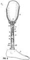
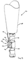
- Fig. 1 illustrates one example of a prosthesis 10 .
- the prosthesis includes a socket 12 for receiving an amputee's residual limb, a column (pylon) 14 , which is typically a cylindrical section of lightweight metal such as aluminum, and an artificial foot 17.
- the pylon 14 includes a vacuum actuator button 16 used to actuate an electric vacuum pump within the pylon that draws air from the socket 12 and, as a result, draws the residual limb into intimate contact with the interior of the socket 12 .
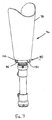
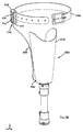
- Fig. 2 illustrates the prosthesis of Fig. 1 in a disassembled state to show the component parts within the pylon 14 .
- a power source 20 such as a capacitor or a conventional 9-volt battery
- a vacuum pump 22 Internal to the pylon 14 is a power source 20 , such as a capacitor or a conventional 9-volt battery, a vacuum pump 22 , and electrical lines 24 for delivering electrical power from power source 20 to vacuum pump 22 , and vacuum line 26 for drawing vacuum from socket 12 through a check valve 27 .
- the power source 20 , vacuum pump 22, electrical lines 24, vacuum line 26 and check valve 27 components are inserted into the pylon 14 after insertion of a ribbon 28, so that the ribbon 28 may be subsequently used to extract the components (e.g., for changing or recharging the power source 20 ).
- VMP 1624 Series of vacuum pumps available from Virtual Industries, Inc., 2130 Vector Place, Colorado Springs Colorado.
- a specific model that has been found to be particularly suitable for application as shown herein is model 1624-009-S.
- This family of pumps is capable of drawing vacuum up to 18 inches of mercury (-594 millibar), which is sufficient for use in a prosthesis.
- the pump flow rate is as large as 1300 mm per minute.
- the voltage for the specific model identified above is 9 volts, permitting use of the pump with a conventional disposable or rechargeable 9-volt battery.
- a rechargeable 8 volt lithium ion polymer battery (model LIPBA-300-8, rated at 300mAh/8v) available from OPRA-TECH Engineering in Warren, Ohio may also be used.
- Another line of pumps suitable for use in any embodiment of the present invention are available from the Oken Seiko Co., Ltd. in Tokyo, Japan.
- One particular pump model that has shown itself acceptable in this regard is model S02R6331, which can operate on between 1.5-3.0 volts. Consequently, such a pump may be powered by a small capacitor, 1-2, 1.5v AAA disposable or rechargeable batteries, or any other acceptable standard batteries.
- electrically-powered vacuum pumps are available having a size and weight that permits their installation on or within the pylon 14 , a housing, or another component of a prosthesis without substantially increasing the effort and drain on the patient using the prosthesis.
- such pumps can be easily incorporated into a portable inflation pump such as is illustrated in Fig. 5 below.
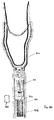
- Fig. 3 is a cross-sectional view of the prosthetic device 10 illustrating the components of Fig. 2 after insertion into the pylon 14 .
- the ribbon 28 forms a loop surrounding the power source 20 and the vacuum pump 22 so that those components may be withdrawn from the pylon 14 by pulling at the ends 28a and 28b of ribbon which extend to the bottom end of pylon.
- Fig. 3 further illustrates the vacuum and electrical circuits formed by the various components of the prosthetic device 10 . Specifically, an electrical circuit is formed by the electrical connections 24 , the positive and negative contacts of the power source 20 and the positive and negative terminals of vacuum pump 22 .
- one electrical connection directly connects one terminal of the power source 20 to one terminal of vacuum pump 22 , while further electrical connections connect the other terminal of the power source to the other terminal of vacuum pump via electrical switch 16 .
- electrical switch 16 electrical power is supplied to the vacuum pump 22 , causing the vacuum pump to operate and evacuate the socket 12 .
- a user of a prosthetic device as thus described can readily create elevated vacuum to any level desired, at least to the limits of vacuum that can be drawn by the vacuum pump 22 .
- No particular vacuum level is required or contemplated by this particular example, as individual patients may have specific preferences and physical and/or physiological needs that dictate the level of vacuum drawn.
- the described exemplary vacuum pumps each have a flow rate sufficient to evacuate a typical socket to the desired vacuum level within about 30 seconds of vacuum pump operation. Some users will require very little vacuum within the socket 12, whereas others will desire a higher level of vacuum and may, therefore, operate the vacuum pump for a longer period of time. For example, certain levels of vacuum may be desirable due to their potential to reduce the risk of ulceration and improve vascular flow. Furthermore, the amputee may readily re-apply vacuum using the pump as described above as needed.
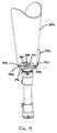
- the vacuum line 26 connects the vacuum pump 22 to a vacuum orifice 30 located in the socket 12 so that the socket may be evacuated by operation of the vacuum pump.
- air drawn through the vacuum line 26 in this example is expelled via an outlet port 22b on vacuum pump 22 into the interior of the pylon 14 . Air expelled into the pylon 14 is vented to the atmosphere, as the interior of a typical pylon is not generally sealed from the atmosphere.
- the vacuum line 26 includes a check valve 27 for permitting airflow through the vacuum tube 26 to the vacuum pump 22 but preventing reverse airflow from the vacuum pump through the vacuum tube and into the socket 12.
- the check-valve 27 may be a duckbill-valve or another known type of one-way valve.
- a patient's residual limb 40 typically having a liner donned thereon, is inserted into the socket 12 , commonly leaving a cavity 42 filled with air.
- an air wick sheath such as a fabric can be used to prevent the urethane or thermoplastic liner from sealing the vacuum orifice and thus limiting the vacuum to the opening of the orifice only.
- Use of an air wick sheath over such a liner can allow air to be evacuated over a larger area of the residual limb.
- a fabric covered liner such as one of the Alpha ® family of liners available from The Ohio Willow Wood Company in Mt. Sterling, Ohio is used, the use of an air wick sheath is unnecessary.
- the patient depresses the actuator button 16, activating the vacuum pump 22 and causing air from the cavity 42 to be drawn through the vacuum tube 26 and the check valve 27 to the vacuum pump 22, whereafter the air is expelled into the interior of the pylon 14.
- the resulting vacuum in the cavity 42 draws the residual limb 40 into tight coupling with the interior of the socket 12, and permits use of the prosthetic device 10 for various ambulatory activities.
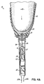
- the vacuum induced coupling between the residual limb 40 and the interior of the socket 12 can be best observed in Fig. 4B .
- the pylon 14 is simplified by not including therein the vacuum pump 22 or the power source 20. Rather, the pylon 14 contains only the vacuum line 26 that is coupled to the interior of the socket 12.
- the vacuum line 26 connects to a vacuum orifice coupler 50/52, which includes two parts.
- a first part of the coupler 50/52 is a check valve 50 that permits airflow from the socket 12 through the vacuum line 26, but blocks reverse airflow from the exterior environment into the vacuum line and socket.
- the coupler 50/52 may also include an orifice 52 for receiving a vacuum line from an external portable vacuum pump 56.
- a portable evacuation device 56 includes its own vacuum line 54 with a coupler 55 on the end thereof for connection to the vacuum orifice coupler 52.
- the interior of the portable evacuation device 56 includes a power source 60, such as a capacitor or battery, a vacuum pump 62, and a control switch 66.
- the power source 60 is electrically connected to the vacuum pump 62 via electrical connections similar or identical to those described above with reference to Figs. 2-4B , and the vacuum line 54 is connected to the inlet port of the vacuum pump 62.
- the portable evacuation device can thus be used to draw air from the socket 12 by connecting the coupler 55 to the coupler 52, then actuating switch 66 to activate vacuum pump 62 and draw the air through the vacuum line 54.
- a portable evacuation device as shown in Fig. 5 is that the weight of the power source 60 and the vacuum pump 62, although minimal, is removed from the prosthesis. Also, a patient with a relatively long residual limb and, therefore, a short pylon 14, may not have sufficient volume in the pylon to enclose the motor and/or power source therein as shown in the preceding drawings. Similarly, above-knee amputees may not have enough room to incorporate a vacuum system between a prosthetic knee coupler and the end of the user's socket. In such cases, a portable evacuation device may be utilized to provide a portable vacuum source for the amputee.
- FIG. 6 Another example is illustrated in Figure 6 .
- a vacuum pump and power source are again installed to a pylon.
- the vacuum pump, power source and pylon may be the vacuum pump 22, power source 20 and pylon 14 shown in Figs. 2-4B , for example, or may be entirely different components.
- this example makes use of a special sleeve 68 into which the vacuum pump 22 and power source 20 are installed prior to insertion into the pylon 14.
- the sleeve 68 is formed from a thin and lightweight material that may substantially conform to the shape of the pylon interior.
- the sleeve 68 consists of a thin plastic tube, although the use of other materials is certainly also possible.
- One or both ends of the sleeve 68 may be open, or the end(s) may be closed but for small access openings required for vacuum lines or electrical wiring.
- the vacuum pump 22 and power source 20 may be retained within the sleeve 68 simply by a tight fit between the components and the interior of the sleeve.
- the sleeve interior may be provided with a special geometry designed to mate with and retain the vacuum pump 22 and/or power source 20.
- a retention means may take many forms such as, for example, a pin, fastener, tab or other retainer that releasably affixes the sleeve 68 to the pylon 14 .
- Various types of releasable adhesive such as one or more pieces of double-stick tape or Velcro ® may also be used for this purpose. As shown in Fig.
- a detent 70 More specifically, when the sleeve 68 is properly inserted into the pylon 14 , a projection 72 located on the exterior of the housing engages a hole or aperture 74 provided in the wall of the pylon. The interaction between the projection 72 and the aperture 74 is sufficient to retain the sleeve 68 during normal use of an associated prosthesis, while also allowing for disengagement and deliberate removal of the sleeve if desired.
- the sleeve 68 may be used in any embodiment of the present invention wherein a vacuum pump and power source are installed within a hollow prosthetic component.
- a prosthetic limb 76 includes an evacuation device 80 having at least a vacuum pump 84 and power source 86 located in a housing 82 that is specially designed to mate with a universal distal adapter 88 that is affixed to or integrated into a prosthetic socket 78 .
- a distal adapter 88 is shown to be substantially located in the distal end of the prosthetic socket 78 in Figs. 8-12 , and may employ the four-hole attachment pattern common to the prosthetics industry.
- a proximal (mounting) face 88a of the distal adapter 88 that resides interior to the socket 78 is preferably, but not necessarily, concave, to better receive the distal end of the residual limb.
- the distal adapter 88 also has an aperture 90 passing axially therethrough.
- the aperture 90 allows for the passage of various suspension components such as, for example, locking pins and lanyards, and also receives a portion of the evacuation device housing 82 when the evacuation device 80 is used.
- Suspension devices associated with such suspension components can be designed to mate with the distal adapter 88 in the same manner as the evacuation device 80 , and theses devices may be made to be interchangeable.
- the distal adapter 88 is optionally, but not necessarily, equipped with one or more o-rings 92 or similar sealing elements that traverse its periphery and assist with providing an air-tight seal between the outer surface of the distal adapter 88 and the interior of the socket 78 .
- Other sealing means may also be employed.
- a number of mounting projections 94 each having a flat mounting surface 96 , extend downward from a bottom (connecting) face 88b of this distal adapter 88 and are exposed along the bottom of the distal end 78b of the socket 78.
- This can be achieved during lamination of the socket 78 by employing a temporary cover plate to protect the mounting surfaces 96 and the aperture 90 , while simultaneously allowing socket material to fill the channels formed between the mounting projections 94 .
- the end result of this technique is a substantially flat mounting area at the distal end 78b of the socket 78 , with an aperture that connects the interior of the socket to the atmosphere via the aperture 90 in the distal adapter 88 .
- a distal adapter having a single uniform mounting surface that is exposed along the distal end 78b of the socket 78 may alternatively be used in place of an adapter having mounting projections.
- each mounting surface 96 has a threaded mounting hole 98 for receiving a like-threaded fastener.
- the mounting surfaces 96 mate with the proximal (mounting) side 82a of the evacuation device housing 82 when the evacuation device 80 is affixed to the distal end of the socket 78 .
- the housing 82 has a number of thru-holes 100 that are arranged to align with the mounting holes 98 located in the mounting surfaces 96 of the distal adapter 88. Fasteners may be passed through the thru-holes 100 in the housing 82 and threaded into the distal adapter mounting holes 98 to secure the evacuation device 80 to the distal end of the socket 78.
- prosthetic components may be affixed to the distal (connecting) side 82b of the evacuation device housing 82 by the same fasteners.
- These prosthetic components may include, for example, pyramid adapters, Symes adapters, prosthetic ankles, prosthetic feet, prosthetic knees, and other components forming the remainder of a prosthesis.
- a sealing extension 102 projects upward from the mounting face 82a of the evacuation device housing 82 through the aperture 90 in the distal end 78b of the socket 78 and into the aperture 90 in the distal adapter 88.
- the sealing extension 102 preferably carries an o-ring 104 that acts to seal the aperture 90 in the distal adapter 88.
- the distal end 78b of the socket 78 is made air tight.
- mating vacuum passages 106, 108 extend through the distal adapter 88 and the distal end 78b of the socket 78.
- the vacuum passage 108 in the socket 78 may be created during lamination by means of a projection on the cover plate used to expose the mounting faces 96 of the mounting projections 94.
- the vacuum passage 108 may be bored through the distal end 78b of the socket 78 after lamination thereof.
- the interface of the vacuum passages 106, 108 may be further sealed with an o-ring 110 if desired.
- Such an o-ring 110 may be installed into a recess or counterbore 112 in the distal adapter 88 .
- an evacuation device vacuum passage 114 extends from the vacuum pump 84 through the mounting surface 82a of the evacuation device housing 82 .
- the evacuation device vacuum passage 114 is aligned and mates with the vacuum passages 108 , 106 in the socket 108 and distal adapter 106 when the evacuation device 80 is properly mounted to the distal end 78b of the socket 78 .
- An o-ring 116 or similar sealing element may be located in the mounting face 82a of the evacuation device housing 82 and around the evacuation device vacuum passage 114 to ensure a good seal.
- the connected vacuum passages 106, 108, 114 essentially form one continuous vacuum passageway 118 that allows the vacuum pump 84 of the evacuation device 80 to evacuate air from the interior of the socket 78.
- a one way valve may be placed in any of the vacuum passages 106, 108, 114 to ensure that air cannot flow into the socket 78.
- Air evacuated from the socket may be discharged by the vacuum pump 84 through an exhaust port 120.
- the exhaust port 120 may reside at various locations in the housing 82.
- the evacuated air may be discharged directly to the atmosphere, or into another prosthetic component, such as a pylon, where it can thereafter leak to the atmosphere.
- a one-way valve and/or muffler can be associated with the exhaust port 120.
- an evacuation device vacuum passage may pass from a vacuum pump through the sealing extension 102 - instead of through the mounting face 82a of the housing 82.
- communication with the socket interior occurs through the aperture 90 in the distal adapter 88 and, therefore, the distal adapter vacuum passage 106 and socket vacuum passage 108 can be eliminated or plugged.
- an actuator button 122 protrudes through the housing 82 for easy access by the user.
- Other actuating means may also be used, some of which are described in more detail below.
- Access to the vacuum pump 84, power source 86 and/or other components located within the evacuation device 80 may be accomplished through one or more access holes or panels (not shown) located in a side(s) of the evacuation device housing 82.
- the connecting face 82b of the evacuation device housing 82 may comprise a removable plate 124 that can be detached as needed to provide access to the vacuum pump 84, power source 86, and/or other components located within the evacuation device housing 82.
- the universal distal adapter 88 can allow for the interchangeability of various suspension devices, such as the evacuation device, a pin lock device, or a locking lanyard device. Each such device employs the same hole pattern so as to properly mate with the distal adapter 88.
- the aperture 90 in the distal adapter is of sufficient size to allow the passage of a suspension component (e.g., a locking pin or lanyard), but can also be sealed (as described above) when suction suspension is employed.
- a prosthetic limb 126 includes an evacuation device 130 for evacuating a prosthetic socket 128 .
- the evacuation device 130 includes a housing 132 containing at least a vacuum pump 134 and power source 136.
- the housing 132 is designed to fit around a prosthetic pylon 138 .
- the housing 132 may have two halves that can be fastened together around the pylon 138 .
- a housing may be of substantially one-piece construction having a passageway therethrough for receiving a pylon. Such a housing may be retained on the pylon through an interference fit, or by a clamping means, for example.
- the housing 132 may be contoured.
- the housing 132 may be contoured in a similar fashion to a human calf, or some other appropriate or pleasing shape.
- the vacuum pump 134 may be connected to the interior of the socket 128 by a vacuum line 140 that runs through the pylon 138 - in which case an aperture is provided through the pylon for passage of the vacuum line.
- the vacuum line 140 may extend from the vacuum pump 134, through the housing 132 and distal end of the socket 128, and into the socket interior.
- a vacuum line 140 may extend from the vacuum pump 134, through the housing 132, and to a manifold (such as the manifold 290 described in detail below), which manifold provides for communication with the socket interior so that air can be drawn therefrom.
- An actuator button 146 may extend through the housing for easy access by the user.
- Other actuating means may also be, some of which are described in more detail below.
- Air evacuated from the socket may be discharged by the vacuum pump 134 through an exhaust port 148.
- the exhaust port 148 may reside at various locations in the housing 132.
- a one-way valve and/or muffler can be associated with the exhaust port 148.
- Access to the vacuum pump 134 , power source 136 and/or other components located within the evacuation device housing 132 may be accomplished by separating the halves of the evacuation device housing.
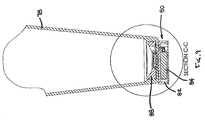
- an evacuation device 154 includes at least a vacuum pump 166 and power source 168 contained within a housing 156 that is attached to a side wall of a socket 152 of a prosthetic limb 150.
- the housing 156 is affixed to a mounting adapter 158 that is built directly into the socket 152, such as during the lamination thereof.
- a vacuum passage 160 may extend through the mounting adapter 158 and socket sidewall, and into to the interior of the socket 152. Air may be evacuated from the socket interior by drawing it through the vacuum passage 160 using the vacuum pump 166.
- Air evacuated from the socket 152 may be discharged by the vacuum pump 166 through an exhaust port 170.
- the exhaust port 170 may reside at various locations in the housing 156 or in the mounting adapter 158. When a manifold is used, an exhaust port may be located therein.
- a one-way valve and/or muffler can be associated with the exhaust port 170 regardless of its location.
- a prosthetic limb 172 is provided with an evacuation device 176 comprised of at least a vacuum pump 182 and power source 184 residing within a housing 180 that is integral to a side wall of a prosthetic socket 174.
- the housing 180 protrudes form the side wall of the socket 174 and forms a chamber 186 within which the vacuum pump 182 and power source 184 are retained.
- the housing 180 may be a separate component that is laminated or otherwise bonded to the socket 174 after the socket is formed. Preferably, however, the housing 180 is formed along with the socket 174.
- the vacuum pump 182 and power source 184 may be permanently sealed within the chamber 186 .
- a removable interior cover 188 may be provided to ensure that the vacuum pump 182 , power source 184 , and any other associated components remain within the chamber 186, while allowing access thereto when required.
- a vacuum passage 190 or vacuum line may extend into the interior of the socket 174. When an interior cover 188 is present, the vacuum passage 190 or a vacuum line may extend therethrough. Air is evacuated from the socket interior by the vacuum pump 182 via the vacuum passage 190 .
- Air evacuated from the socket may be discharged by the vacuum pump 182 through an exhaust port 192 .
- the exhaust port 192 may reside at various locations in the housing 180.
- a one-way valve and/or muffler can be associated with the exhaust port 192.
- a vacuum line may run from the vacuum pump 166, 182, through the housing 156, 180, and to a manifold connected to the socket 152, 174 , such as, for example, the manifold 290 depicted in Fig. 19 .
- the manifold provides access to the interior of the socket 152, 174, such that air may be drawn therefrom by the vacuum pump 166, 182 .
- a vacuum line may run from the vacuum pump 166, 182, through the housing 156, 180, and to a vacuum passage located more remotely from the evacuation device, such as on the bottom surface of the socket.
- an evacuation device 196 including at least a vacuum pump 200 and power source 202 located in a housing 198 , is positioned within an exoskeletal prosthetic device 194 . More specifically, the housing 198 is located within a cavity 204 between a socket portion 206 and distal end 208 of the exoskeletal prosthetic device 194 .
- an exoskeletal prosthetic device 194 may account for a majority of a prosthetic leg or prosthetic arm, for example.
- the evacuation device 196 may be secured within the exoskeletal prosthetic device 194 in any number of ways.
- the evacuation device 196 includes a housing 198 , straps, clips, tabs, releasable adhesives, Velcro ® , and any number of other types of retainers may be secured to the interior of the exoskeletal prosthetic device 194 and used to engage and retain the housing.
- Such retainers can also be provided to individually secure the vacuum pump 200 and power source 202 within the exoskeletal prosthetic device 194 in embodiments of the present invention wherein no evacuation device housing is used.
- a mounting pad, plate or other such structure may be fabricated or otherwise secured within the cavity 204 of the exoskeletal prosthetic device 194 to provide an attaching surface 210 for the housing.
- the housing 198 may be secured to the attaching surface 210 using any of the retainers mentioned above, or by screws, double-sided tape, or any other known means.
- a vacuum passage 212 extends into the interior of the socket 206 .
- a vacuum line 214 connects the vacuum pump 200 of the evacuation device 196 to the socket interior via the vacuum passage 212 . Air is evacuated from the socket interior by the vacuum pump 200 using the vacuum passage 212 and vacuum line 214.
- Air drawn from the socket interior may be discharged by the vacuum pump 200 directly to the atmosphere through an exhaust port 216 in the exoskeletal prosthetic device 194.
- air evacuated from the socket interior may be discharged into the cavity 204 in the exoskeletal prosthetic device 194, where it may thereafter leak to the atmosphere through one or more component interfaces or be released through the exhaust port 216 which, in this case, may be manually or automatically actuable.
- Any exhaust port associated with any variation of this embodiment of the present invention may include a one-way valve and/or muffler.
- Fig. 16 depicts another example, wherein an evacuation device 222 is affixed to a mounting plate 230 that is designed to be mounted between adjacent components of a prosthetic limb 218.
- the evacuation device 222 includes a housing 224 that contains at least a vacuum pump 226 and power source 228, the housing adapted for affixation to an attachment face 232 of the mounting plate 230.
- the vacuum pump 226 and power source 228 may be individually affixed to the attachment face 232 of the mounting plate 230 without a housing.
- the mounting plate 230 is preferably L-shaped, such that a mounting portion 234 thereof can be located between adjacent components of the prosthetic limb 218, while the attachment face 232 extends substantially parallel to the length of the prosthetic limb.
- the mounting plate 230 may be located between for example, without limitation, a prosthetic ankle and foot, or a prosthetic socket 220 and a pyramid adapter 236 .
- a vacuum line 238 may run from the vacuum pump 226 , through the housing 224 , if present, and into a vacuum passage 240 located in the socket 220 of the prosthetic limb 218 .
- the vacuum line 238 may run between the vacuum pump 226 and socket 220 completely exterior to the prosthetic limb 218 , as shown, or may be routed at least partially within the mounting portion 234 , a pylon 242 , and/or other components of the prosthetic limb.
- Those portions of the vacuum line 238 that run exterior to the prosthetic limb 218 are preferably, but not necessarily, releasably secured to neighboring limb components.
- a vacuum line may run from the vacuum pump 226 (through the housing 224 , if present) to a manifold connected to the socket 220 , such as, for example, the manifold 290 depicted in Fig. 19 .
- the manifold provides access to the interior of the socket 220 , such that air can be drawn therefrom.
- any of the above-described routings of the vacuum line 238 may be employed.
- Air evacuated from the socket 220 may be discharged to the atmosphere by the vacuum pump 226 .
- the evacuated air may be discharged through an exhaust port 244 , which may be located in/on the vacuum pump 226 , or at various locations in the housing 224 (if present). When a manifold is used, an exhaust port may be located therein.
- a one-way valve and/or muffler can be associated with the exhaust port, regardless of its location.
- Fig. 17 shows another example wherein an evacuation device 250 is located within a prosthetic foot 246 (which may be a solid prosthetic foot or a hollow foot covering).
- the evacuation device 250 may consist of a vacuum pump 254 and associated power source 256 that reside within a cavity 248 in the foot 246 .
- the evacuation device 250 also includes a housing 252 that contains the vacuum pump 254 and power source 256 and is located in the prosthetic foot cavity 248.
- a vacuum line 258 may run from the vacuum pump 254 , through the prosthetic foot 246 , and into a vacuum passage 260 located in the socket 262 of the prosthetic limb 264 .
- the vacuum line 258 may run between the vacuum pump 254 and socket 262 completely exterior to the prosthetic limb 264 , as shown, or may be routed at least partially within a pylon 266 and/or other components of the prosthetic limb. As an example of this latter construction, the vacuum line 258 might be routed from within the foot through a prosthetic ankle and pylon, and into the distal end of the socket.
- Those portions of the vacuum line 258 that run exterior to the prosthetic limb 264 are preferably, but not necessarily, releasably secured to neighboring limb components.
- the vacuum line 258 may run from the vacuum pump 254 to a manifold connected to the socket 262 , such as, for example, the manifold 290 depicted in Fig. 19 .
- the manifold provides access to the interior of the socket 262 , such that air can be drawn therefrom.
- a manifold is used, either of the above-described routings of the vacuum line 258 may be employed.
- Air evacuated from the socket by the vacuum pump 254 may be discharged to the atmosphere, preferably through an exhaust port 268 located in the prosthetic foot 246 .
- an exhaust port may be located therein.
- a one-way valve and/or muffler can be associated with the exhaust port, regardless of its location.
- FIG. 18 illustrates another example, wherein an evacuation device 270 includes a housing 272 containing at least a vacuum pump 274 and power source 276 , the evacuation device being located on the user's person and provided to evacuate a socket 278 of a prosthetic limb 280 .
- this example of the evacuation device 270 may clipped or otherwise attached to a user's belt 282 .
- the evacuation device 270 may be placed in a pocket or temporarily attached to some other piece of a user's attire.
- the housing 272 may have an attachment mechanism such as a spring-loaded clip integral thereto or, alternatively, the housing may fit into a sleeve or similar holder that acts to temporarily secure the evacuation device 270 to a user's attire.
- Such a holder may operate, for example, much like a clip-on cell phone holder.
- a vacuum line 284 may run from the vacuum pump 274 , through the housing 272 , and into a vacuum passage 286 located in the socket 278 of the prosthetic limb 280 .
- the vacuum line 284 may be routed at least partially under the user's clothing. Those portions of the vacuum line 284 that run exterior to the prosthetic limb 280 are preferably, but not necessarily, releasably secured to the prosthetic socket 278.
- the vacuum line 284 may run from the vacuum pump 274 to a manifold connected to the socket 278 , such as, for example, the manifold 290 depicted in Fig. 19 .
- the manifold provides access to the interior of the socket 278 , such that air can be drawn therefrom.
- Air evacuated from the socket 278 by the vacuum pump 274 may be discharged to the atmosphere, preferably through an exhaust port 288 located in the housing 272.
- an exhaust port may be located therein.
- a one-way valve and/or muffler can be associated with the exhaust port, regardless of its location.
- Fig. 19 depicts yet another example, wherein a manifold 290 is provided to connect a vacuum source 292 to the interior of a prosthetic socket 294.
- the vacuum source 292 may be an evacuation device of the present invention, a hand-operated vacuum pump, or some other vacuum device that can be connected to the manifold 290.
- the manifold 290 is associated with and attached to the distal end of the prosthetic socket 294. It should be realized, however, that it would also be possible to attach such a manifold to other portions of the prosthetic socket 294, as long as the attached location permits access to the interior portion of the socket that is to be evacuated.
- a vacuum passageway 296 extends through the manifold 290.
- One end 298 of the vacuum passageway 296 is adapted to connect with or receive a vacuum line 302 that connects the manifold 290 to the vacuum source 292.
- the other end 300 of the vacuum passageway 296 is adapted to align with a vacuum passage 304 that extends through the socket wall.
- the vacuum passage 304 extends through the distal end of the socket 294, but could be located elsewhere in other embodiments.
- An o-ring 306 or other sealing element may be located at the interface of the vacuum passageway 296 and the vacuum passage 304 to help ensure an air-tight seal.
- the manifold 290 may be attached to the socket 294 in a number of different ways.
- the manifold 290 may be laminated or otherwise bonded to the socket 294.
- the manifold 290 may be secured to a mounting plate 308 that has been integrated into the socket 294.
- the manifold 290 could also be affixed to the universal distal adapter 88 shown in Figs. 8-12 .
- the vacuum source 292 air is drawn from the socket interior through the manifold 290.
- the evacuated air may be discharged through an exhaust port associated with the vacuum source 292 or from some other location.
- a one-way valve and/or muffler can be associated with the exhaust port, regardless of its location.
- a magnetic switch 310 may be used in place of an actuator button or other vacuum pump actuator that requires direct contact by the user. As shown, the magnetic switch 310 resides between a power source 312 and a motor of a vacuum pump 314. When actuated, the magnetic switch 310 allows current to flow from the power source 312 to the motor, activating the vacuum pump 314 and initiating the evacuation process.
- actuation of the magnetic switch 310 can often take place through the material forming, for example, an evacuation device housing (see above), a prosthetic socket 316, or a prosthetic pylon 318 (as shown). More specifically, in many embodiments of the present invention, a user can activate and deactivate the evacuation device simply by holding a small magnetic activator 320 in close proximity to the magnetic switch 310. Magnetic attraction between the magnetic activator 320 and the magnetic switch 310 either activates or deactivates the evacuation device as desired. Selective activation and deactivation can be accomplished, for example, by reversing the field of the magnetic activator 320 or by changing the location thereof with respect to the magnetic switch 310.
- a vacuum pump of the present invention may be operated by various power sources, such as one or more batteries or capacitors.
- evacuation devices of the present invention are preferably provided with easy access to the power source(s) and/or, more preferably, employ a rechargeable power source(s).
- recharging can be accomplished by either direct or inductive charging.
- the power source is connected to a plug-in charger that transfers electrical energy to the power source using the electrical circuitry of the evacuation device.
- an evacuation device may have a housing that includes a charging jack that is connected to the contacts of the power source. The power source of such an embodiment can then be recharged simply by plugging an external charger into the charging jack.
- an evacuation device of the present invention with self-charging capabilities.
- a small inductive generator may be located on the prosthetic limb and placed in electrical communication with the evacuation device power source.
- Such a generator may be constructed and located on the prosthetic limb such that movement of the prosthetic limb during ambulation of the amputee will generate electric power by causing relative motion of coils within a magnetic field. Electrical energy produced by the generator is then provided to the evacuation device power source to maintain the power source in an acceptably charged state.
- EAP electro active polymer
- EAP materials have evolved into a very viable alternative to other energy generation methods, and although EAP generators do have some limitations, these limitations are not insurmountable in a prosthetic device application.
- sufficient charging energy could also be generated using piezoelectric element generators. Piezoelectric elements generate a voltage in response to applied mechanical stress and, therefore, can be caused to generate electrical energy by movement of a prosthetic limb to which they are attached.
- an evacuation device of the present invention also includes any electrical circuitry necessary to receive electrical energy from the generator(s), and may also include circuitry and/or other elements to prevent over-charging of the power source(s).
- each embodiment may include basic through advanced versions thereof. More particularly, each embodiment of an evacuation device of the present invention may include a basic version that provides for manual operation only, an advanced version that is fully automatic, and one or more versions having operational features that fall somewhere therebetween.
- each embodiment of an evacuation device of the present invention can provide for manual operation.
- Manual operation essentially involves a user engaging an actuator that results in activation of a vacuum pump and evacuation of the prosthetic socket.
- the vacuum pump will continue to evacuate the socket until the user releases the actuator or the vacuum level reaches the maximum level that can be achieved by the pump.
- manual operation allows a user to select a vacuum level that best corresponds to his/her current activity level or desired comfort level. Vacuum can be periodically increased or decreased as desired by the user.
- Each embodiment of an evacuation device of the present invention may also operate in a semi-automatic mode. This can be achieved by adding certain types of sensors to the vacuum system, thereby requiring only minimal user interaction. For example, in a simplistic embodiment of semi-automatic operation, a pressure switch may be provided and simply configured to prevent the vacuum level from exceeding some level previously found to be uncomfortable or otherwise inappropriate for the user.
- a vacuum pump is preset to draw a particular level of vacuum once activated. Therefore, the single intermittent push of a push-button or other actuator will cause the vacuum pump to operate until an associated pressure sensor determines that the desired pressure has been met. It is also possible to mix modes of operation by allowing the user to enter a semi-automatic mode with a quick contact of the actuator, but to enter a manual mode by prolonged contact with the actuator.
- an evacuation device of the present invention can be further enhanced by adding either logic or a microprocessor.
- a microprocessor it is possible to monitor socket pressure and automatically maintain the socket pressure within a patient or practitioner defined range of acceptable pressures. This automatic mode of operation completely eliminates the need for the user to monitor the socket pressure, and the prosthetic limb then becomes a device that can simply be donned and forgotten until removal thereof is desired. It can be appreciated that such a vacuum suspension system will be able to automatically react to conditions within the socket in a manner appropriate for the user, and in ways not possible for a mechanical pump design.
- sensors and a microprocessor to an evacuation device of the present invention and/or to a prosthetic limb equipped with such an evacuation device, permits the monitoring of various conditions or parameters of the prosthetic limb and/or the user. For example, by appropriately locating a basic pressure transducer in the prosthetic socket, the measuring and tracking of various pressure values associated with the prosthetic socket becomes possible. Pressure values of interest may include maximum or minimum socket pressure, the average pressure in the socket over some period of time, and the Root Mean Square (RMS) pressure over a defined period of time.
- RMS Root Mean Square
- the period of time monitored might depend on the conditions that the user or a practitioner is evaluating.
- the time period might be set to a single step.
- the time period might be extended to obtain a target range for all of the various ways that the activity at issue might be performed.
- the test period might even be extended to a period of days to track values for the user's entire range of activities.
- Another parameter that may be tracked is some measure of the amount of pressure the user is exposed to over the course of a period of time. Measure of this parameter would be the integral of pressure as a function of time, or the integral of the pressure squared as a function of time.
- Another mode of monitoring the prosthetic socket is a high speed real time mode.
- vacuum level variations within the socket can be monitored in real time, as they occur. Data is then recorded relative to a known time base and allows vacuum fluctuations to be ascribed to specific events during the user's activities.
- This mode also allows graphical displays to be constructed that can be used to visualize the relationship between a user's activities and the vacuum level within the socket.
- vacuum level within the socket is or can be monitored
- This method of monitoring the level of user activity and automatically adjusting the vacuum to a correlating level results in a system that continually attempts to keep the vacuum level in the socket at an appropriate level.
- basic power, pressure, and functional information can be communicated to the user through simple LED indicators.
- Such an interface may continually display information, or it may display information only when the patient requests it in order to conserve power.
- Such a display can be built into the evacuation device housing, if present.
- basic information regarding evacuation device function, etc. can be communicated to the user by means of an audio transducer.
- One benefit of this design is that it does not require the user to view the evacuation device or some other display unit associated therewith.
- Pushbuttons may be used in a very basic operating and/or programming interface. Pushbuttons are simple, easy to understand, and draw no power when they are not active. Used with a properly designed low-power microprocessor, pushbuttons account for very little power consumption. There are a number of types of switches or switch-type devices that could actually be used. Standard contact switches are one choice. Membrane-type switches may be a reliable, attractive, and space efficient alternative. Also, proximity or capacitive detection switches have recently become available that are able to detect "touches" through a closed container and, as such, would eliminate the need for a passage from the outside of an evacuation device housing or prosthetic component to the inside. Another possibility is a Hall-type device that operates by using some sort of magnetic key. Such a device might be used to provide simple on/off control, perhaps as a backup to other more advanced interfaces.
- More complex interfaces may be associated with more complex evacuation devices of the present invention, such as the semi-automatic and automatic versions described above.
- One such interface may be comprised of a series of pushbuttons associated with the evacuation. These pushbuttons may be located, for example, on an evacuation device housing.
- the disadvantage to such an interface is that it requires the patient to remove clothing, or possibly cosmetic fittings, to activate the vacuum pump, update a program, or make changes to the vacuum settings.
- an evacuation device of the present invention may include a radio, cellular or some other form of wireless transmitter/receiver.
- a wireless link with the transmitter may then be established in any of several ways.
- a stand-alone communication device is used to communicate with the evacuation device.
- a stand-alone communication device may be embodied in a key fob, which may include, for example, an integrated transmitter/receiver, input keys, and an alphanumeric and/or graphical display.
- a key fob may include, for example, an integrated transmitter/receiver, input keys, and an alphanumeric and/or graphical display.
- This design would allow a user to keep the key fob in their pocket and to communicate with the evacuation device easily and inconspicuously. This also allows the user to observe actual operating conditions and parameters associated with the evacuation device and/or prosthesis, and to optimize evacuation device operation to best suit their needs.
- a transmitter/receiver may be integrated into a communication device having a computer compatible interface, such as a serial or USB interface.
- a computer e.g., a PC, laptop, pen computer, PDA, etc.
- the communication device could be connected to a computer and thereafter used to wirelessly communicate with the evacuation device. This would be especially useful to a practitioner, who could then easily observe variations in a user's socket pressure through a step, and from step to step, so as to evaluate the function of the evacuation device. A practitioner could also adjust the evacuation device settings, and then save the settings to a hard disk or other storage medium.
- wireless communication devices that may be used in conjunction with an evacuation device of the present invention.
- Such wireless communication devices could also be used to interact with an evacuation device in more complex ways, such as in troubleshooting and programming, for example. It is intended that all interactions capable of being performed locally could also be performed using a wireless link.
- an evacuation device of the present invention be equipped with a means to notify the user of a low power state and/or to take action(s) directed to preserving the power remaining in the power source.
- One method of alerting a user to a low power state is by cycling the vacuum pump. That is, by repeatedly turning the vacuum pump on and off during the evacuation process, additional vibration and noise will be generated. While such cycling is unlikely to appreciably decrease the amount of power consumed, the additional vibration and noise can serve as a cue to the user that there is a problem.
- a user may be similarly alerted to a low power situation by running the vacuum pump motor at a higher speed than normal. This would increase motor and/or vacuum pump noise, helping to alert the user is aware to the low power situation.
- reducing the required vacuum level can be practiced. This method may be employed directly by a user with a manually operable evacuation device, or automatically by a microprocessor controlled device. An automatic reduction in vacuum level may also serve to notify the user of a low power situation.
- the wireless (radio) link may be disabled once a low power state is detected. Although minimal, such a radio link does draw some power from the power source when enabled. Disabling the radio link would also force the user to manually activate the evacuation device, thus making the low power state very apparent.
- Yet another method of conserving electric power would be to disable the automatic control system, if present. This would prevent the possibly frequent cycling of the evacuation device, especially if the user's activity level is increasing. This action would also force the user to interact with the evacuation device in an alternate fashion that would make the low power condition apparent. Disabling the automatic control system could also allow a user to temporarily disable the evacuation device if the user's current activity level does not necessitate suction suspension - thereby preserving power to adjust the vacuum level should the user's activity level change.
- a visual and/or audible alert may be employed, such as through the use of the LED or audio transducer interfaces described above.
- sensors, a microprocessor, and other devices may be associated with an evacuation device to form a more advanced prosthetic evacuation system.
- Such systems may provide for a number of operational modes that offer various advantages in function, convenience, and privacy.
- One such operational mode is a multi-speed vacuum mode.
- the vacuum pump motor operates at a reduced level of performance, but also at a reduced noise level. Therefore, in this multi-speed vacuum mode of operation, the user may choose between one of several predetermined levels of vacuum pump performance - with lower performance levels producing less noise and higher performance levels producing more noise. Thus, for example, if the user is in a noise sensitive environment (e.g., the theater, a library, etc.) and their activity level is relatively low, the user may choose a lower performance level to minimize noise. If noise is of little or no concern, then the user might select a higher performance level.
- a noise sensitive environment e.g., the theater, a library, etc.
- a level of activity monitor In addition to vacuum pump performance level selection by the user, another way to take advantage of the multi-speed vacuum mode of operation would be to use a level of activity monitor, as described above. Such a level of activity monitor could be used to detect the level of activity of the user and to subsequently adjust the performance of the vacuum pump to an appropriate level. This would have the additional advantage of reducing power consumption when the user is substantially sedentary.
- An evacuation device of the present invention may also be used to assist with doffing (removal) of the prosthesis to which it is installed.
- the user When removal is desired, the user first typically removes a sealing sleeve, if present, and subsequently releases the vacuum in the socket by either placing a tool therein to open a passageway along the socket interior or by opening or otherwise activating an air valve. With the vacuum released, the prosthesis can then be removed from the residual limb.
- an evacuation device of the present invention may employ a reversible vacuum pump to pump air back into the distal end of the socket and encourage its dislodgement from the residual limb.
- an evacuation device of the present invention may use two pumps; one to evacuate the socket during donning of a prosthesis and one to pressurize the socket during doffing of the prosthesis.
- an evacuation device of the present invention can also have therapeutic uses.
- Amputees are often the victims of chronic wounds that seemingly will not heal. These wounds are sometimes the result of operations, and sometimes result from pressure sores.
- One of the dilemmas frequently faced by amputees is how to let their stump heal when its use is often necessary to their daily activities. While this dilemma is not unique to upper or lower limb amputees, it may be more problematic for lower limb amputees because they must rely on their residual limbs for ambulation and because their residual limbs are generally subjected to more forces and pressures than are those of upper limb amputees.
- An evacuation device of the present invention can be used with a sealable socket to provide such a vacuum therapy regimen.
- the socket may be for treatment use only and may be disposable to obviate any concerns relating to the seepage of wound fluids during treatment.
- Such a socket may be especially useful for the treatment of new amputees.
- the socket may be part of a prosthesis.
- the evacuation device When incorporated into the stump socket of a prosthesis, the evacuation device may be programmed to enter a therapy mode when the amputee is inactive. This may be useful when the amputee has a wound(s) or other condition(s) that will benefit from vacuum therapy.
- the evacuation device is programmed or otherwise set to achieve the desired vacuum level when operated.
- the evacuation device is further programmed to cycle on and off in order to repeatedly apply and release the vacuum, and to maintain the vacuum level for the necessary time - whatever that time is determined to be.
- a residual limb motion sensor can be integrated into a prosthetic socket, and used to adjust the vacuum level therein. If motion over some period of time is too high, more vacuum is drawn. If the vacuum level has been maintained, but the user's activity level has declined, the vacuum level can be slowly reduced until motion is detected. The vacuum level can then be increased as necessary until the motion ends or is maintained at a level for which the current vacuum level is appropriate. Over time, a map of activity level vs. pressure (vacuum level) can be constructed and referenced to allow for quicker vacuum adjustments.
- the motion sensor may be comprised of a Hall sensor placed in the base of a prosthetic socket and a small magnet fastened to the tip of a prosthetic liner worn over the residual limb.
- the motion sensor may be comprised of a mutual inductance device that measures the mutual inductance between a coil in the base of a prosthetic socket, and a small coil placed on the tip of a prosthetic liner worn over the residual limb.
- the motion sensor may be comprised of an ultrasonic sensor that is tuned to detect a small metal plate mounted on the tip of a prosthetic liner worn over the residual limb.
- the motion sensor may be comprised of a force sensor placed in the bottom of a prosthetic socket. Intermittent contact of the residual limb with the force sensor will indicate the occurrence of residual limb motion within the socket.
Claims (26)
- Un dispositif prothétique, comprenant :une emboîture (78) destinée à recevoir un membre résiduel ;un adaptateur (88) situé à l'intérieur de ladite emboîture (78) le long d'une extrémité distale intérieure de celle-ci, une face proximale (88a) dudit adaptateur (88) faisant face à l'intérieur de l'emboîture et conçue pour recevoir une extrémité distale d'un membre résiduel tandis qu'une surface extérieure dudit adaptateur (88) est en butée avec une paroi intérieure de ladite emboîture (78) ;des passages de vide alignés (106, 108) passant à travers ledit adaptateur (88) et ladite emboîture (78), lesdits passages de vide (106, 108) permettant l'évacuation de l'air depuis un intérieur de ladite emboîture à travers ledit adaptateur (88) ;un dispositif d'évacuation (80) comprenant une pompe à vide électrique (84) et une source d'énergie électrique (86) toutes deux situées à l'intérieur d'un logement (82), ledit logement (82) conçu pour être couplé à une surface de dessous dudit adaptateur (88), une paroi de dessous dudit adaptateur (78) étant en contact avec et piégée entre ceux-ci ; etun passage de vide (114) passant à travers ledit logement (82), ledit passage de vide (114) aligné avec lesdits passages de vide (106, 108) dans ledit adaptateur (88) et ladite emboîture (78) lorsque ledit dispositif d'évacuation (80) est correctement monté sur ce dernier ;où ledit passage de vide (114) dans ledit logement et lesdits passages de vide (106, 108) dans ledit adaptateur (88) et ladite emboîture (78) forment une voie de passage de vide continue (118) et ladite pompe à vide (84) peut être actionné pour vider ladite emboîture (78) en aspirant de l'air de celle-ci à travers ladite voie de passage de vide (118) tandis que ledit membre résiduel est situé à l'intérieur de ladite emboîture (78) et ledit dispositif d'évacuation (80) est correctement monté sur ledit adaptateur (88).
- Le dispositif prothétique de la revendication 1, où ledit adaptateur (88) fait intégralement partie de ladite emboîture (78).
- Le dispositif prothétique de la revendication 1, comprenant en outre un joint torique (110) entre ledit passage de vide (106) dans ledit adaptateur (88) et ledit passage de vide (108) dans ladite emboîture (78).
- Le dispositif prothétique de la revendication 1, où ledit dispositif d'évacuation (80) est attaché sur ledit adaptateur (88) en faisant passer un certain nombre de dispositifs de fixation filetés à travers des trous de réception (100) dans ledit logement (82) et en vissant lesdits dispositifs de fixation dans des trous de montage taraudés de façon analogue (98) dans ledit adaptateur (88).
- Le dispositif prothétique de la revendication 4, où chaque trou de montage (98) réside dans une surface de montage d'adaptateur correspondante (96) qui est exposée le long d'un dessous de ladite emboîture (78).
- Le dispositif prothétique de la revendication 1, où ledit adaptateur (88) inclut une ouverture axiale (90) destinée à permettre le passage de travers celui-ci de divers composants de suspension prothétiques.
- Le dispositif prothétique de la revendication 1, où ledit logement (82) est conçu pour un raccordement à un composant parmi une pluralité de composants prothétiques.
- Le dispositif prothétique de la revendication 7, où ledit composant prothétique est un adaptateur pyramidal.
- Le dispositif prothétique de la revendication 1, comprenant en outre un orifice d'échappement (120) dans ledit logement (82) à travers lequel l'air vidé est éliminé.
- Le dispositif prothétique de la revendication 9, comprenant en outre une valve antireflux et/ou un silencieux associé(s) audit orifice d'échappement (120).
- Le dispositif prothétique de la revendication 1, comprenant en outre un actionneur (122) s'étendant à travers ledit logement (82) pour permettre à un utilisateur d'actionner ladite pompe à vide (84) par contact continu avec ledit actionneur (122).
- Le dispositif prothétique de la revendication 1, comprenant en outre un commutateur magnétique (310) entre ladite source d'énergie (86) et ladite pompe à vide (84), ledit commutateur magnétique (310) permettant un actionnement à distance de ladite pompe à vide (84).
- Le dispositif prothétique de la revendication 1, comprenant en outre un ou plusieurs capteurs et un microprocesseur en communication avec ledit dispositif d'évacuation (80).
- Le dispositif prothétique de la revendication 13, où au moins un capteur est un capteur de niveau de vide qui surveille le niveau de vide à l'intérieur de ladite emboîture.
- Le dispositif prothétique de la revendication 14, où ledit microprocesseur utilise une entrée provenant dudit capteur de niveau de vide pour faire fonctionner ladite pompe à vide (84) de telle sorte que ladite emboîture (78) soit automatiquement vidée jusqu'à un niveau prédéterminé une fois que ladite pompe à vide (84) est initialement actionnée par un utilisateur.
- Le dispositif prothétique de la revendication 15, où ledit microprocesseur est conçu pour utiliser une entrée provenant dudit capteur de niveau de vide pour surveiller de façon continue le niveau de vide à l'intérieur de ladite emboîture (78) et pour faire fonctionner automatiquement ladite pompe à vide (84) autant que nécessaire pour maintenir ladite emboîture (78) à un certain niveau de vide prédéterminé.
- Le dispositif prothétique de la revendication 14, où ledit microprocesseur est conçu pour utiliser une entrée provenant dudit capteur de niveau de vide pour surveiller le niveau de vide à l'intérieur de ladite emboîture (78) et pour faire fonctionner ladite pompe à vide (84) autant que nécessaire pour ajuster automatiquement ledit niveau de vide pour correspondre à des changements dans le niveau d'activité d'un utilisateur.
- Le dispositif prothétique de la revendication 1, comprenant en outre un moyen pour indiquer une condition d'énergie faible à un utilisateur.
- Le dispositif prothétique de la revendication 1, où ladite pompe à vide (84) est réversible pour pressuriser ladite emboîture (78) durant le retrait d'un membre prothétique associé (76).
- Le dispositif prothétique de la revendication 1, comprenant en outre une deuxième pompe à vide pour pressuriser ladite emboîture (78) durant le retrait d'un membre prothétique associé (76).
- Le dispositif prothétique de la revendication 1, comprenant en outre un récepteur/émetteur sans fil associé audit dispositif d'évacuation (80) pour permettre une communication sans fil avec celui-ci.
- Le dispositif prothétique de la revendication 1, où ladite source d'énergie (86) est rechargeable.
- Le dispositif prothétique de la revendication 22, comprenant en outre un générateur monté sur un membre prothétique (76) avec lequel ledit dispositif prothétique est utilisé, ledit générateur rechargeant ladite source d'énergie (86) avec de l'énergie électrique automatiquement produite par ledit générateur en conséquence du déplacement dudit membre prothétique (76).
- Le dispositif prothétique de la revendication 23, où ledit générateur est composé d'un dispositif d'inductance, d'un élément piézo-électrique, ou d'un polymère électroactif.
- Le dispositif prothétique de la revendication 1, où ladite pompe à vide (84) est cyclable pour aspirer et relâcher du vide de façon répétée à l'intérieur de ladite emboîture, permettant ainsi audit dispositif prothétique de fournir une thérapie sous vide audit membre résiduel.
- Le dispositif prothétique de la revendication 1, où :ledit adaptateur (88) inclut une pluralité de trous de réception de dispositif de fixation fileté (98) ; etledit logement (82) est conçu pour être couplé audit adaptateur (88) par une pluralité de dispositifs de fixation filetés qui passent à travers des trous de passage de dispositif de fixation (100) dans ledit logement et dans lesdits trous de réception de dispositif de fixation (98) dans ledit adaptateur (88).
Priority Applications (2)
| Application Number | Priority Date | Filing Date | Title |
|---|---|---|---|
| EP16166750.6A EP3075360B1 (fr) | 2005-06-10 | 2006-06-12 | Dispositif prothétique dans lequel est utilisée une pompe à vide électrique |
| EP17191840.2A EP3287102A1 (fr) | 2005-06-10 | 2006-06-12 | Dispositif prothétique dans lequel est utilisée une pompe à vide électrique |
Applications Claiming Priority (3)
| Application Number | Priority Date | Filing Date | Title |
|---|---|---|---|
| US11/149,858 US7914586B2 (en) | 2005-06-10 | 2005-06-10 | Prosthetic device utilizing electric vacuum pump |
| PCT/US2006/022742 WO2006135851A2 (fr) | 2005-06-10 | 2006-06-12 | Dispositif prothetique dans lequel est utilisee une pompe a vide electrique |
| US11/423,632 US7947085B2 (en) | 2005-06-10 | 2006-06-12 | Prosthetic device utilizing electric vacuum pump |
Related Child Applications (2)
| Application Number | Title | Priority Date | Filing Date |
|---|---|---|---|
| EP16166750.6A Division EP3075360B1 (fr) | 2005-06-10 | 2006-06-12 | Dispositif prothétique dans lequel est utilisée une pompe à vide électrique |
| EP17191840.2A Division EP3287102A1 (fr) | 2005-06-10 | 2006-06-12 | Dispositif prothétique dans lequel est utilisée une pompe à vide électrique |
Publications (3)
| Publication Number | Publication Date |
|---|---|
| EP1887991A2 EP1887991A2 (fr) | 2008-02-20 |
| EP1887991A4 EP1887991A4 (fr) | 2010-09-15 |
| EP1887991B1 true EP1887991B1 (fr) | 2016-04-27 |
Family
ID=37532868
Family Applications (1)
| Application Number | Title | Priority Date | Filing Date |
|---|---|---|---|
| EP06772881.6A Active EP1887991B1 (fr) | 2005-06-10 | 2006-06-12 | Dispositif prothetique dans lequel est utilisee une pompe a vide electrique |
Country Status (4)
| Country | Link |
|---|---|
| US (2) | US7947085B2 (fr) |
| EP (1) | EP1887991B1 (fr) |
| CA (1) | CA2611492C (fr) |
| WO (1) | WO2006135851A2 (fr) |
Families Citing this family (71)
| Publication number | Priority date | Publication date | Assignee | Title |
|---|---|---|---|---|
| US8956421B2 (en) | 2007-02-06 | 2015-02-17 | Deka Products Limited Partnership | Dynamic support apparatus and system |
| US8074559B2 (en) | 2007-02-06 | 2011-12-13 | Deka Products Limited Partnership | Dynamic support apparatus and system |
| WO2005039444A2 (fr) * | 2003-10-24 | 2005-05-06 | Collier Milo S | Dispositif prothetique a depression |
| US20090030435A1 (en) * | 2004-09-27 | 2009-01-29 | Theranova, Llc | Method and apparatus for anchoring cardiovascular implants |
| US8652217B2 (en) * | 2005-06-10 | 2014-02-18 | The Ohio Willow Wood Company | Prosthetic device utilizing electric vacuum pump |
| US8016892B2 (en) | 2005-06-10 | 2011-09-13 | The Ohio Willow Wood Company | Prosthetic device utilizing electric vacuum pump |
| US8016776B2 (en) * | 2005-12-02 | 2011-09-13 | Medtronic, Inc. | Wearable ambulatory data recorder |
| DE102006025476B4 (de) | 2006-05-30 | 2015-05-28 | Otto Bock Healthcare Gmbh | Orthopädietechnisches Gerät |
| US7662191B2 (en) * | 2006-06-30 | 2010-02-16 | össur hf | Liner donning and doffing device |
| US8007543B2 (en) * | 2006-09-12 | 2011-08-30 | OrthoCare Innovations, Inc. | Vacuum attachment system |
| US9241812B2 (en) * | 2006-09-12 | 2016-01-26 | James Jay Martin | Control system for prosthesis |
| US8303670B2 (en) * | 2006-09-12 | 2012-11-06 | Orthocare Innovations, Llc | Pump system for prosthesis |
| JP2010512177A (ja) | 2006-12-08 | 2010-04-22 | ハンガー オーソペディック グループ インコーポレイテッド | 真空を使用する人工装具デバイスおよび接続システム |
| US9259332B2 (en) * | 2006-12-14 | 2016-02-16 | Lincolnshire Manufacturing, Llc | Prosthetic vacuum system |
| US9814606B2 (en) * | 2006-12-14 | 2017-11-14 | Morris J. Danzig | Prosthetic vacuum system |
| US11779476B2 (en) | 2007-02-06 | 2023-10-10 | Deka Products Limited Partnership | Arm prosthetic device |
| WO2008098057A2 (fr) | 2007-02-06 | 2008-08-14 | Deka Integrated Solutions Corp. | Prothèse de bras |
| US8979943B2 (en) | 2007-02-06 | 2015-03-17 | Deka Products Limited Partnership | Arm prosthetic device |
| US9114030B2 (en) | 2007-02-06 | 2015-08-25 | Deka Products Limited Partnership | System for control of a prosthetic device |
| US8449624B2 (en) | 2007-02-06 | 2013-05-28 | Deka Products Limited Partnership | Arm prosthetic device |
| US8870970B2 (en) * | 2007-02-06 | 2014-10-28 | Deka Products Limited Partnership | Dynamic support apparatus |
| US8864845B2 (en) | 2007-02-06 | 2014-10-21 | DEKA Limited Partnership | System for control of a prosthetic device |
| US8821587B2 (en) | 2007-02-06 | 2014-09-02 | Deka Products Limited Partnership | Apparatus for control of a prosthetic |
| US10426638B2 (en) | 2007-02-06 | 2019-10-01 | Deka Products Limited Partnership | Arm prosthetic device |
| WO2009023818A1 (fr) * | 2007-08-15 | 2009-02-19 | Theranova, Llc | Procédé et appareil pour la stérilisation active et automatique de dispositifs entièrement implantés |
| US10842653B2 (en) | 2007-09-19 | 2020-11-24 | Ability Dynamics, Llc | Vacuum system for a prosthetic foot |
| GB0723855D0 (en) | 2007-12-06 | 2008-01-16 | Smith & Nephew | Apparatus and method for wound volume measurement |
| JP5676434B2 (ja) * | 2008-06-06 | 2015-02-25 | ハンガー オーソペディック グループ インコーポレイテッド | 補綴装置および真空を使った接続システム |
| US9603558B2 (en) | 2008-08-15 | 2017-03-28 | Theranova, Llc | Methods and devices for the diagnosis and treatment of diabetes |
| CA2761806C (fr) | 2009-04-13 | 2017-08-15 | Deka Products Limited Partnership | Systeme et appareil pour commande d'orientation |
| WO2011035253A1 (fr) | 2009-09-18 | 2011-03-24 | Mahon Joseph A | Interfaces prothétiques réglables et systèmes et procédés associés |
| WO2011100118A2 (fr) * | 2010-02-12 | 2011-08-18 | Freedom Innovations, L.L.C. | Dispositif et procédé de mesure d'angle |
| GB201015656D0 (en) | 2010-09-20 | 2010-10-27 | Smith & Nephew | Pressure control apparatus |
| US9662058B2 (en) | 2011-03-07 | 2017-05-30 | Potrero Medical, Inc. | Sensing Foley catheter |
| WO2014099527A1 (fr) | 2012-12-17 | 2014-06-26 | Theranova, Llc | Appareil portable pour le traitement ou la prévention de l'ostéopénie et de l'ostéoporose, pour la stimulation de la croissance osseuse, le maintien ou l'amélioration de la densité minérale osseuse et l'inhibition de l'adipogenèse |
| US8876743B2 (en) * | 2011-04-20 | 2014-11-04 | Vivonics, Inc. | Conformable material for an orthotic device and method of making same |
| US9067003B2 (en) | 2011-05-26 | 2015-06-30 | Kalypto Medical, Inc. | Method for providing negative pressure to a negative pressure wound therapy bandage |
| US9066822B2 (en) | 2011-06-23 | 2015-06-30 | Northwestern University | Vacuum pump systems for prosthetic limbs and methods of using the same |
| US10238511B1 (en) | 2011-08-12 | 2019-03-26 | Kaione R. Newton | Electromagnetic suspension system for prosthetic device |
| US9155634B2 (en) * | 2011-08-16 | 2015-10-13 | Rehabilitation Institute Of Chicago | Systems and methods of myoelectric prosthesis control |
| US9125730B2 (en) | 2011-10-31 | 2015-09-08 | Ossur Hf | Orthopedic device for dynamically treating the knee |
| US9084845B2 (en) | 2011-11-02 | 2015-07-21 | Smith & Nephew Plc | Reduced pressure therapy apparatuses and methods of using same |
| US9615945B2 (en) | 2011-11-29 | 2017-04-11 | Otto Bock Healthcare Gmbh | Prosthetic valve and vacuum adapter system |
| DE102011119593B4 (de) | 2011-11-29 | 2013-12-24 | Otto Bock Healthcare Gmbh | Adapter und Prothesensystem |
| DE102011119591B3 (de) * | 2011-11-29 | 2013-05-29 | Otto Bock Healthcare Gmbh | Prothese mit einer peristaltischen Pumpe |
| DE102012011681B4 (de) | 2012-06-14 | 2015-04-09 | Otto Bock Healthcare Gmbh | Adapter und Prothesensystem |
| US9198780B2 (en) | 2012-02-14 | 2015-12-01 | Ossur Hf | Vacuum assisted suspension system |
| US20150351941A1 (en) * | 2012-02-16 | 2015-12-10 | Katherine E. BOMKAMP | Pain free socket system and associated method |
| AU2013256565B2 (en) | 2012-04-30 | 2015-12-03 | Ossur Hf | Prosthetic device, system and method for increasing vacuum attachment |
| US20130338793A1 (en) * | 2012-06-13 | 2013-12-19 | Ralph E. BERNAQUER, JR. | Sealing member for vacuum suspension prosthetic device |
| US10413437B2 (en) | 2013-01-25 | 2019-09-17 | Ossur Iceland Ehf | Orthopedic device having a dynamic control system and method for using the same |
| WO2014124275A1 (fr) | 2013-02-07 | 2014-08-14 | Ossur Hf | Ensemble plaque de montage pour dispositif prothétique |
| EP2961356B1 (fr) | 2013-03-01 | 2018-05-09 | Össur HF | Système de suspension à vide |
| WO2014205103A1 (fr) | 2013-06-21 | 2014-12-24 | Ossur Hf | Système de tension dynamique pour dispositif orthopédique |
| US9757256B2 (en) | 2014-07-01 | 2017-09-12 | Ossur Hf | Pump mechanism for vacuum suspension system |
| US9744056B2 (en) | 2014-08-06 | 2017-08-29 | Rehabilitation Institute Of Chicago | Magnetic electrical connector for assistive devices |
| EP3533419A1 (fr) | 2014-09-02 | 2019-09-04 | The Ohio Willow Wood Company | Systèmes pour commande de suspension de vide intelligente |
| WO2016069839A1 (fr) | 2014-10-31 | 2016-05-06 | Ossur Hf | Dispositif orthopédique ayant un système de commande dynamique |
| US10028845B2 (en) * | 2015-01-08 | 2018-07-24 | Ossur Iceland Ehf | Pump mechanism |
| EP3297582B1 (fr) | 2015-05-21 | 2019-04-17 | Ossur Iceland EHF | Système de pompe |
| US10179055B2 (en) * | 2015-05-29 | 2019-01-15 | Ossur Iceland Ehf | Pump system for use with a prosthetic device |
| EP3340941B1 (fr) | 2015-08-27 | 2021-11-10 | Ossur Iceland EHF | Système de pompe |
| US10806604B2 (en) | 2015-09-04 | 2020-10-20 | Northwestern University | Vacuum pump systems for prosthetic limbs and methods of using the same |
| WO2018039421A1 (fr) | 2016-08-26 | 2018-03-01 | Ossur Iceland Ehf | Système de pompe. |
| US11547590B2 (en) | 2017-11-27 | 2023-01-10 | Ossur Iceland Ehf | Orthopedic device having a suspension element |
| DE102017131193A1 (de) * | 2017-12-22 | 2019-06-27 | Otto Bock Healthcare Products Gmbh | Vorrichtung zum Festlegen zweier orthopädietechnischer Komponenten aneinander |
| DE102017131195A1 (de) | 2017-12-22 | 2019-06-27 | Otto Bock Healthcare Products Gmbh | Versorgungssystem für orthopädietechnische Komponente und Verfahren |
| CN113164265A (zh) | 2018-11-12 | 2021-07-23 | 奥索冰岛有限公司 | 包含基于细丝的结构的医疗器材 |
| CN109938892B (zh) * | 2019-04-03 | 2020-08-04 | 河北工业大学 | 一种智能膝上假肢穿戴者骑行状态识别系统 |
| CN112137777B (zh) * | 2019-06-26 | 2021-11-16 | 上海交通大学 | 人工肛门括约肌装置体外控制系统 |
| US11883306B2 (en) | 2019-11-12 | 2024-01-30 | Ossur Iceland Ehf | Ventilated prosthetic liner |
Family Cites Families (27)
| Publication number | Priority date | Publication date | Assignee | Title |
|---|---|---|---|---|
| US5591217A (en) | 1995-01-04 | 1997-01-07 | Plexus, Inc. | Implantable stimulator with replenishable, high value capacitive power source and method therefor |
| US6287345B1 (en) | 1995-08-18 | 2001-09-11 | The Ohio Willow Wood Company | Valve assembly for a prosthetic limb |
| US5658353A (en) * | 1995-10-31 | 1997-08-19 | Layton; Harry W. | Method for donning or doffing an artificial limb |
| US5840047A (en) | 1996-04-16 | 1998-11-24 | Prosthetic Sensing Technologies, Llc | Sensor device for monitoring a prosthetic device |
| US5888212A (en) * | 1997-06-26 | 1999-03-30 | Mauch, Inc. | Computer controlled hydraulic resistance device for a prosthesis and other apparatus |
| US6063125A (en) | 1997-02-14 | 2000-05-16 | Ohio Willow Wood Company | Suspension/alignment for prosthetic limbs |
| US6137889A (en) * | 1998-05-27 | 2000-10-24 | Insonus Medical, Inc. | Direct tympanic membrane excitation via vibrationally conductive assembly |
| US6508842B1 (en) | 1999-06-03 | 2003-01-21 | Barbara J. Caspers | Socket liner for artificial limb |
| US20010016781A1 (en) | 1999-06-03 | 2001-08-23 | Caspers Carl A. | Osmotic membrane and vacuum system for artificial limb |
| US6554868B1 (en) * | 1999-06-03 | 2003-04-29 | Carl A. Caspers | Vacuum pump and shock absorber for artificial limb |
| US6726726B2 (en) | 1999-06-03 | 2004-04-27 | Otto Bock Healthcare Lp | Vacuum apparatus and method for managing residual limb volume in an artificial limb |
| US20040098136A1 (en) | 1999-06-03 | 2004-05-20 | Caspers Carl A. | Socket liner for artificial limb with permanent attachment to socket |
| US7922775B2 (en) | 1999-06-03 | 2011-04-12 | Otto Bock Healthcare Lp | Pulsating pressure chamber and method for fluid management |
| US6926742B2 (en) | 1999-06-03 | 2005-08-09 | Otto Bock Healthcare Lp | Plate/socket attachment for artificial limb vacuum pump |
| US6645253B2 (en) * | 1999-06-03 | 2003-11-11 | Carl A. Caspers | Vacuum pump and shock absorber for artificial limb |
| US6585774B2 (en) | 2000-04-25 | 2003-07-01 | Simbex, Llc | Dynamic variable geometry fitting system for use with a body appliance |
| US6905519B2 (en) * | 2001-06-15 | 2005-06-14 | Bionix Prosthetic Solutions, Inc. | Method of forming transfemoral sockets and lock adapter therefor |
| US7655049B2 (en) * | 2001-07-26 | 2010-02-02 | Phillips Van L | Socket insert having a bladder system |
| US6610096B2 (en) | 2001-08-22 | 2003-08-26 | Macdonald Stuart G. | Prosthetic implants having enhanced utility |
| WO2003079940A2 (fr) | 2002-03-19 | 2003-10-02 | The Board Of Trustees Of The University Of Illinois | Systeme et procede d'equilibrage et de pose de protheses articulaires |
| WO2003086245A2 (fr) * | 2002-04-12 | 2003-10-23 | James Jay Martin | Systeme prothetique a commande electronique |
| US7150762B2 (en) * | 2002-11-01 | 2006-12-19 | Otto Bock Healthcare Lp | Pressure/temperature monitoring device for prosthetics |
| US20060212128A1 (en) * | 2005-03-16 | 2006-09-21 | Jaems E. And Joyce E. Smith | Artificial limb assembly having microprocessor-controlled vacuum pump |
| US20070055383A1 (en) * | 2005-09-08 | 2007-03-08 | Charles King | Vacuum assisted heat/perspiration removal system and limb volume management for prosthetic device |
| US20070112439A1 (en) | 2005-11-17 | 2007-05-17 | Panucialman Peter V | Power evacuation valve for prosthetic limb socket |
| US9241812B2 (en) * | 2006-09-12 | 2016-01-26 | James Jay Martin | Control system for prosthesis |
| US7670386B2 (en) * | 2006-12-18 | 2010-03-02 | Wisys Technology Foundation | Prosthetic socket with real-time dynamic control of pressure points |
-
2006
- 2006-06-12 WO PCT/US2006/022742 patent/WO2006135851A2/fr active Application Filing
- 2006-06-12 EP EP06772881.6A patent/EP1887991B1/fr active Active
- 2006-06-12 CA CA2611492A patent/CA2611492C/fr not_active Expired - Fee Related
- 2006-06-12 US US11/423,632 patent/US7947085B2/en active Active
-
2011
- 2011-05-20 US US13/112,942 patent/US20110270413A1/en not_active Abandoned
Also Published As
| Publication number | Publication date |
|---|---|
| WO2006135851A2 (fr) | 2006-12-21 |
| CA2611492C (fr) | 2014-05-13 |
| CA2611492A1 (fr) | 2006-12-21 |
| EP1887991A2 (fr) | 2008-02-20 |
| WO2006135851A3 (fr) | 2007-03-01 |
| US20110270413A1 (en) | 2011-11-03 |
| US7947085B2 (en) | 2011-05-24 |
| US20060282175A1 (en) | 2006-12-14 |
| EP1887991A4 (fr) | 2010-09-15 |
Similar Documents
| Publication | Publication Date | Title |
|---|---|---|
| EP1887991B1 (fr) | Dispositif prothetique dans lequel est utilisee une pompe a vide electrique | |
| EP3075360B1 (fr) | Dispositif prothétique dans lequel est utilisée une pompe à vide électrique | |
| US8016892B2 (en) | Prosthetic device utilizing electric vacuum pump | |
| US8652217B2 (en) | Prosthetic device utilizing electric vacuum pump | |
| US20060212128A1 (en) | Artificial limb assembly having microprocessor-controlled vacuum pump | |
| US20070213839A1 (en) | Artificial limb assembly having microprocessor-controlled vacuum pump | |
| US9814606B2 (en) | Prosthetic vacuum system | |
| US8303670B2 (en) | Pump system for prosthesis | |
| US8277515B2 (en) | Vacuum attachment system | |
| US9820873B2 (en) | Vacuum suspension system | |
| US20160250045A1 (en) | Prosthetic device utilizing electric vacuum pump | |
| CA2726371C (fr) | Dispositif prothetique et systeme de raccordement employant du vide | |
| EP2144578B1 (fr) | Raccord pneumatique pour emboîture prothétique |
Legal Events
| Date | Code | Title | Description |
|---|---|---|---|
| PUAI | Public reference made under article 153(3) epc to a published international application that has entered the european phase |
Free format text: ORIGINAL CODE: 0009012 |
|
| 17P | Request for examination filed |
Effective date: 20071227 |
|
| AK | Designated contracting states |
Kind code of ref document: A2 Designated state(s): AT BE BG CH CY CZ DE DK EE ES FI FR GB GR HU IE IS IT LI LT LU LV MC NL PL PT RO SE SI SK TR |
|
| DAX | Request for extension of the european patent (deleted) | ||
| RIN1 | Information on inventor provided before grant (corrected) |
Inventor name: DENUNE, JEFFREY, A. Inventor name: GROVES, MARK, W. Inventor name: FORD, MARK, W. Inventor name: KELLEY, CHRISTOPHER, T. Inventor name: HAYNES, MICHAEL, L. Inventor name: COLVIN, JAMES, M. Inventor name: HAINES, WILBUR, A. |
|
| DAX | Request for extension of the european patent (deleted) | ||
| A4 | Supplementary search report drawn up and despatched |
Effective date: 20100818 |
|
| 17Q | First examination report despatched |
Effective date: 20110524 |
|
| GRAP | Despatch of communication of intention to grant a patent |
Free format text: ORIGINAL CODE: EPIDOSNIGR1 |
|
| INTG | Intention to grant announced |
Effective date: 20150701 |
|
| GRAP | Despatch of communication of intention to grant a patent |
Free format text: ORIGINAL CODE: EPIDOSNIGR1 |
|
| INTG | Intention to grant announced |
Effective date: 20151112 |
|
| GRAS | Grant fee paid |
Free format text: ORIGINAL CODE: EPIDOSNIGR3 |
|
| GRAA | (expected) grant |
Free format text: ORIGINAL CODE: 0009210 |
|
| AK | Designated contracting states |
Kind code of ref document: B1 Designated state(s): AT BE BG CH CY CZ DE DK EE ES FI FR GB GR HU IE IS IT LI LT LU LV MC NL PL PT RO SE SI SK TR |
|
| REG | Reference to a national code |
Ref country code: GB Ref legal event code: FG4D |
|
| REG | Reference to a national code |
Ref country code: CH Ref legal event code: EP |
|
| REG | Reference to a national code |
Ref country code: AT Ref legal event code: REF Ref document number: 793917 Country of ref document: AT Kind code of ref document: T Effective date: 20160515 |
|
| REG | Reference to a national code |
Ref country code: FR Ref legal event code: PLFP Year of fee payment: 11 |
|
| REG | Reference to a national code |
Ref country code: IE Ref legal event code: FG4D |
|
| REG | Reference to a national code |
Ref country code: DE Ref legal event code: R096 Ref document number: 602006048877 Country of ref document: DE |
|
| REG | Reference to a national code |
Ref country code: NL Ref legal event code: FP |
|
| REG | Reference to a national code |
Ref country code: LT Ref legal event code: MG4D |
|
| REG | Reference to a national code |
Ref country code: AT Ref legal event code: MK05 Ref document number: 793917 Country of ref document: AT Kind code of ref document: T Effective date: 20160427 |
|
| PG25 | Lapsed in a contracting state [announced via postgrant information from national office to epo] |
Ref country code: PL Free format text: LAPSE BECAUSE OF FAILURE TO SUBMIT A TRANSLATION OF THE DESCRIPTION OR TO PAY THE FEE WITHIN THE PRESCRIBED TIME-LIMIT Effective date: 20160427 Ref country code: LT Free format text: LAPSE BECAUSE OF FAILURE TO SUBMIT A TRANSLATION OF THE DESCRIPTION OR TO PAY THE FEE WITHIN THE PRESCRIBED TIME-LIMIT Effective date: 20160427 Ref country code: FI Free format text: LAPSE BECAUSE OF FAILURE TO SUBMIT A TRANSLATION OF THE DESCRIPTION OR TO PAY THE FEE WITHIN THE PRESCRIBED TIME-LIMIT Effective date: 20160427 |
|
| PG25 | Lapsed in a contracting state [announced via postgrant information from national office to epo] |
Ref country code: ES Free format text: LAPSE BECAUSE OF FAILURE TO SUBMIT A TRANSLATION OF THE DESCRIPTION OR TO PAY THE FEE WITHIN THE PRESCRIBED TIME-LIMIT Effective date: 20160427 Ref country code: PT Free format text: LAPSE BECAUSE OF FAILURE TO SUBMIT A TRANSLATION OF THE DESCRIPTION OR TO PAY THE FEE WITHIN THE PRESCRIBED TIME-LIMIT Effective date: 20160829 Ref country code: AT Free format text: LAPSE BECAUSE OF FAILURE TO SUBMIT A TRANSLATION OF THE DESCRIPTION OR TO PAY THE FEE WITHIN THE PRESCRIBED TIME-LIMIT Effective date: 20160427 Ref country code: LV Free format text: LAPSE BECAUSE OF FAILURE TO SUBMIT A TRANSLATION OF THE DESCRIPTION OR TO PAY THE FEE WITHIN THE PRESCRIBED TIME-LIMIT Effective date: 20160427 Ref country code: SE Free format text: LAPSE BECAUSE OF FAILURE TO SUBMIT A TRANSLATION OF THE DESCRIPTION OR TO PAY THE FEE WITHIN THE PRESCRIBED TIME-LIMIT Effective date: 20160427 Ref country code: GR Free format text: LAPSE BECAUSE OF FAILURE TO SUBMIT A TRANSLATION OF THE DESCRIPTION OR TO PAY THE FEE WITHIN THE PRESCRIBED TIME-LIMIT Effective date: 20160728 |
|
| PG25 | Lapsed in a contracting state [announced via postgrant information from national office to epo] |
Ref country code: IT Free format text: LAPSE BECAUSE OF FAILURE TO SUBMIT A TRANSLATION OF THE DESCRIPTION OR TO PAY THE FEE WITHIN THE PRESCRIBED TIME-LIMIT Effective date: 20160427 Ref country code: BE Free format text: LAPSE BECAUSE OF FAILURE TO SUBMIT A TRANSLATION OF THE DESCRIPTION OR TO PAY THE FEE WITHIN THE PRESCRIBED TIME-LIMIT Effective date: 20160427 |
|
| REG | Reference to a national code |
Ref country code: DE Ref legal event code: R097 Ref document number: 602006048877 Country of ref document: DE |
|
| PG25 | Lapsed in a contracting state [announced via postgrant information from national office to epo] |
Ref country code: CZ Free format text: LAPSE BECAUSE OF FAILURE TO SUBMIT A TRANSLATION OF THE DESCRIPTION OR TO PAY THE FEE WITHIN THE PRESCRIBED TIME-LIMIT Effective date: 20160427 Ref country code: MC Free format text: LAPSE BECAUSE OF FAILURE TO SUBMIT A TRANSLATION OF THE DESCRIPTION OR TO PAY THE FEE WITHIN THE PRESCRIBED TIME-LIMIT Effective date: 20160427 Ref country code: SK Free format text: LAPSE BECAUSE OF FAILURE TO SUBMIT A TRANSLATION OF THE DESCRIPTION OR TO PAY THE FEE WITHIN THE PRESCRIBED TIME-LIMIT Effective date: 20160427 Ref country code: RO Free format text: LAPSE BECAUSE OF FAILURE TO SUBMIT A TRANSLATION OF THE DESCRIPTION OR TO PAY THE FEE WITHIN THE PRESCRIBED TIME-LIMIT Effective date: 20160427 Ref country code: DK Free format text: LAPSE BECAUSE OF FAILURE TO SUBMIT A TRANSLATION OF THE DESCRIPTION OR TO PAY THE FEE WITHIN THE PRESCRIBED TIME-LIMIT Effective date: 20160427 Ref country code: EE Free format text: LAPSE BECAUSE OF FAILURE TO SUBMIT A TRANSLATION OF THE DESCRIPTION OR TO PAY THE FEE WITHIN THE PRESCRIBED TIME-LIMIT Effective date: 20160427 |
|
| REG | Reference to a national code |
Ref country code: CH Ref legal event code: PL |
|
| PLBE | No opposition filed within time limit |
Free format text: ORIGINAL CODE: 0009261 |
|
| STAA | Information on the status of an ep patent application or granted ep patent |
Free format text: STATUS: NO OPPOSITION FILED WITHIN TIME LIMIT |
|
| REG | Reference to a national code |
Ref country code: IE Ref legal event code: MM4A |
|
| 26N | No opposition filed |
Effective date: 20170130 |
|
| PG25 | Lapsed in a contracting state [announced via postgrant information from national office to epo] |
Ref country code: LI Free format text: LAPSE BECAUSE OF NON-PAYMENT OF DUE FEES Effective date: 20160630 Ref country code: CH Free format text: LAPSE BECAUSE OF NON-PAYMENT OF DUE FEES Effective date: 20160630 |
|
| REG | Reference to a national code |
Ref country code: FR Ref legal event code: PLFP Year of fee payment: 12 |
|
| PG25 | Lapsed in a contracting state [announced via postgrant information from national office to epo] |
Ref country code: SI Free format text: LAPSE BECAUSE OF FAILURE TO SUBMIT A TRANSLATION OF THE DESCRIPTION OR TO PAY THE FEE WITHIN THE PRESCRIBED TIME-LIMIT Effective date: 20160427 Ref country code: IE Free format text: LAPSE BECAUSE OF NON-PAYMENT OF DUE FEES Effective date: 20160612 |
|
| REG | Reference to a national code |
Ref country code: FR Ref legal event code: PLFP Year of fee payment: 13 |
|
| PG25 | Lapsed in a contracting state [announced via postgrant information from national office to epo] |
Ref country code: HU Free format text: LAPSE BECAUSE OF FAILURE TO SUBMIT A TRANSLATION OF THE DESCRIPTION OR TO PAY THE FEE WITHIN THE PRESCRIBED TIME-LIMIT; INVALID AB INITIO Effective date: 20060612 Ref country code: CY Free format text: LAPSE BECAUSE OF FAILURE TO SUBMIT A TRANSLATION OF THE DESCRIPTION OR TO PAY THE FEE WITHIN THE PRESCRIBED TIME-LIMIT Effective date: 20160427 |
|
| PG25 | Lapsed in a contracting state [announced via postgrant information from national office to epo] |
Ref country code: LU Free format text: LAPSE BECAUSE OF NON-PAYMENT OF DUE FEES Effective date: 20160612 Ref country code: TR Free format text: LAPSE BECAUSE OF FAILURE TO SUBMIT A TRANSLATION OF THE DESCRIPTION OR TO PAY THE FEE WITHIN THE PRESCRIBED TIME-LIMIT Effective date: 20160427 |
|
| PG25 | Lapsed in a contracting state [announced via postgrant information from national office to epo] |
Ref country code: BG Free format text: LAPSE BECAUSE OF FAILURE TO SUBMIT A TRANSLATION OF THE DESCRIPTION OR TO PAY THE FEE WITHIN THE PRESCRIBED TIME-LIMIT Effective date: 20160427 |
|
| PGFP | Annual fee paid to national office [announced via postgrant information from national office to epo] |
Ref country code: NL Payment date: 20180613 Year of fee payment: 13 |
|
| REG | Reference to a national code |
Ref country code: NL Ref legal event code: MM Effective date: 20190701 |
|
| PG25 | Lapsed in a contracting state [announced via postgrant information from national office to epo] |
Ref country code: NL Free format text: LAPSE BECAUSE OF NON-PAYMENT OF DUE FEES Effective date: 20190701 |
|
| PG25 | Lapsed in a contracting state [announced via postgrant information from national office to epo] |
Ref country code: FR Free format text: LAPSE BECAUSE OF NON-PAYMENT OF DUE FEES Effective date: 20190630 |
|
| REG | Reference to a national code |
Ref country code: DE Ref legal event code: R081 Ref document number: 602006048877 Country of ref document: DE Owner name: WILLOWWOOD GLOBAL LLC, MOUNT STERLING, US Free format text: FORMER OWNER: OHIO WILLOW WOOD COMPANY, MOUNT STERLING, OHIO, US |
|
| REG | Reference to a national code |
Ref country code: GB Ref legal event code: 732E Free format text: REGISTERED BETWEEN 20211111 AND 20211117 |
|
| P01 | Opt-out of the competence of the unified patent court (upc) registered |
Effective date: 20230523 |
|
| PGFP | Annual fee paid to national office [announced via postgrant information from national office to epo] |
Ref country code: DE Payment date: 20230418 Year of fee payment: 18 |
|
| PGFP | Annual fee paid to national office [announced via postgrant information from national office to epo] |
Ref country code: IS Payment date: 20230524 Year of fee payment: 18 |
|
| PGFP | Annual fee paid to national office [announced via postgrant information from national office to epo] |
Ref country code: GB Payment date: 20230420 Year of fee payment: 18 |