EP1887724B1 - A wavelength division multiplexing passive optical network and its implement method - Google Patents
A wavelength division multiplexing passive optical network and its implement method Download PDFInfo
- Publication number
- EP1887724B1 EP1887724B1 EP06817919.1A EP06817919A EP1887724B1 EP 1887724 B1 EP1887724 B1 EP 1887724B1 EP 06817919 A EP06817919 A EP 06817919A EP 1887724 B1 EP1887724 B1 EP 1887724B1
- Authority
- EP
- European Patent Office
- Prior art keywords
- optical
- signal
- wavelength
- modulated
- uplink
- Prior art date
- Legal status (The legal status is an assumption and is not a legal conclusion. Google has not performed a legal analysis and makes no representation as to the accuracy of the status listed.)
- Active
Links
- 230000003287 optical effect Effects 0.000 title claims description 289
- 238000000034 method Methods 0.000 title claims description 17
- 238000001514 detection method Methods 0.000 claims description 8
- 230000035559 beat frequency Effects 0.000 claims description 5
- 238000013507 mapping Methods 0.000 claims description 2
- 230000005540 biological transmission Effects 0.000 description 32
- 238000010586 diagram Methods 0.000 description 8
- 238000011144 upstream manufacturing Methods 0.000 description 7
- 239000013307 optical fiber Substances 0.000 description 6
- 239000000835 fiber Substances 0.000 description 5
- RYGMFSIKBFXOCR-UHFFFAOYSA-N Copper Chemical compound [Cu] RYGMFSIKBFXOCR-UHFFFAOYSA-N 0.000 description 4
- 238000005516 engineering process Methods 0.000 description 4
- 238000001228 spectrum Methods 0.000 description 4
- 230000001427 coherent effect Effects 0.000 description 3
- 238000011161 development Methods 0.000 description 3
- 238000012423 maintenance Methods 0.000 description 3
- 238000004891 communication Methods 0.000 description 2
- 238000012986 modification Methods 0.000 description 2
- 230000004048 modification Effects 0.000 description 2
- 230000008054 signal transmission Effects 0.000 description 2
- 230000002457 bidirectional effect Effects 0.000 description 1
- 230000007547 defect Effects 0.000 description 1
- 230000002542 deteriorative effect Effects 0.000 description 1
- 230000009977 dual effect Effects 0.000 description 1
- 238000001914 filtration Methods 0.000 description 1
- 230000036039 immunity Effects 0.000 description 1
- 238000011835 investigation Methods 0.000 description 1
- 230000006855 networking Effects 0.000 description 1
- 238000005057 refrigeration Methods 0.000 description 1
- 238000011160 research Methods 0.000 description 1
- 230000002269 spontaneous effect Effects 0.000 description 1
- 238000006467 substitution reaction Methods 0.000 description 1
Images


Classifications
-
- H—ELECTRICITY
- H04—ELECTRIC COMMUNICATION TECHNIQUE
- H04J—MULTIPLEX COMMUNICATION
- H04J14/00—Optical multiplex systems
- H04J14/02—Wavelength-division multiplex systems
- H04J14/0226—Fixed carrier allocation, e.g. according to service
-
- H—ELECTRICITY
- H04—ELECTRIC COMMUNICATION TECHNIQUE
- H04J—MULTIPLEX COMMUNICATION
- H04J14/00—Optical multiplex systems
- H04J14/02—Wavelength-division multiplex systems
- H04J14/0227—Operation, administration, maintenance or provisioning [OAMP] of WDM networks, e.g. media access, routing or wavelength allocation
- H04J14/0241—Wavelength allocation for communications one-to-one, e.g. unicasting wavelengths
- H04J14/0242—Wavelength allocation for communications one-to-one, e.g. unicasting wavelengths in WDM-PON
- H04J14/0245—Wavelength allocation for communications one-to-one, e.g. unicasting wavelengths in WDM-PON for downstream transmission, e.g. optical line terminal [OLT] to ONU
- H04J14/0246—Wavelength allocation for communications one-to-one, e.g. unicasting wavelengths in WDM-PON for downstream transmission, e.g. optical line terminal [OLT] to ONU using one wavelength per ONU
-
- H—ELECTRICITY
- H04—ELECTRIC COMMUNICATION TECHNIQUE
- H04J—MULTIPLEX COMMUNICATION
- H04J14/00—Optical multiplex systems
- H04J14/02—Wavelength-division multiplex systems
- H04J14/0227—Operation, administration, maintenance or provisioning [OAMP] of WDM networks, e.g. media access, routing or wavelength allocation
- H04J14/0241—Wavelength allocation for communications one-to-one, e.g. unicasting wavelengths
- H04J14/0242—Wavelength allocation for communications one-to-one, e.g. unicasting wavelengths in WDM-PON
- H04J14/0245—Wavelength allocation for communications one-to-one, e.g. unicasting wavelengths in WDM-PON for downstream transmission, e.g. optical line terminal [OLT] to ONU
- H04J14/0247—Sharing one wavelength for at least a group of ONUs
-
- H—ELECTRICITY
- H04—ELECTRIC COMMUNICATION TECHNIQUE
- H04J—MULTIPLEX COMMUNICATION
- H04J14/00—Optical multiplex systems
- H04J14/02—Wavelength-division multiplex systems
- H04J14/0227—Operation, administration, maintenance or provisioning [OAMP] of WDM networks, e.g. media access, routing or wavelength allocation
- H04J14/0241—Wavelength allocation for communications one-to-one, e.g. unicasting wavelengths
- H04J14/0242—Wavelength allocation for communications one-to-one, e.g. unicasting wavelengths in WDM-PON
- H04J14/0249—Wavelength allocation for communications one-to-one, e.g. unicasting wavelengths in WDM-PON for upstream transmission, e.g. ONU-to-OLT or ONU-to-ONU
- H04J14/025—Wavelength allocation for communications one-to-one, e.g. unicasting wavelengths in WDM-PON for upstream transmission, e.g. ONU-to-OLT or ONU-to-ONU using one wavelength per ONU, e.g. for transmissions from-ONU-to-OLT or from-ONU-to-ONU
-
- H—ELECTRICITY
- H04—ELECTRIC COMMUNICATION TECHNIQUE
- H04J—MULTIPLEX COMMUNICATION
- H04J14/00—Optical multiplex systems
- H04J14/02—Wavelength-division multiplex systems
- H04J14/0227—Operation, administration, maintenance or provisioning [OAMP] of WDM networks, e.g. media access, routing or wavelength allocation
- H04J14/0241—Wavelength allocation for communications one-to-one, e.g. unicasting wavelengths
- H04J14/0242—Wavelength allocation for communications one-to-one, e.g. unicasting wavelengths in WDM-PON
- H04J14/0249—Wavelength allocation for communications one-to-one, e.g. unicasting wavelengths in WDM-PON for upstream transmission, e.g. ONU-to-OLT or ONU-to-ONU
- H04J14/0252—Sharing one wavelength for at least a group of ONUs, e.g. for transmissions from-ONU-to-OLT or from-ONU-to-ONU
-
- H—ELECTRICITY
- H04—ELECTRIC COMMUNICATION TECHNIQUE
- H04J—MULTIPLEX COMMUNICATION
- H04J14/00—Optical multiplex systems
- H04J14/02—Wavelength-division multiplex systems
- H04J14/0278—WDM optical network architectures
- H04J14/0282—WDM tree architectures
-
- H—ELECTRICITY
- H04—ELECTRIC COMMUNICATION TECHNIQUE
- H04J—MULTIPLEX COMMUNICATION
- H04J14/00—Optical multiplex systems
- H04J14/02—Wavelength-division multiplex systems
- H04J14/0298—Wavelength-division multiplex systems with sub-carrier multiplexing [SCM]
-
- H—ELECTRICITY
- H04—ELECTRIC COMMUNICATION TECHNIQUE
- H04J—MULTIPLEX COMMUNICATION
- H04J14/00—Optical multiplex systems
- H04J14/02—Wavelength-division multiplex systems
- H04J14/0224—Irregular wavelength spacing, e.g. to accommodate interference to all wavelengths
-
- H—ELECTRICITY
- H04—ELECTRIC COMMUNICATION TECHNIQUE
- H04J—MULTIPLEX COMMUNICATION
- H04J14/00—Optical multiplex systems
- H04J14/02—Wavelength-division multiplex systems
- H04J14/0227—Operation, administration, maintenance or provisioning [OAMP] of WDM networks, e.g. media access, routing or wavelength allocation
- H04J14/0241—Wavelength allocation for communications one-to-one, e.g. unicasting wavelengths
- H04J14/0242—Wavelength allocation for communications one-to-one, e.g. unicasting wavelengths in WDM-PON
- H04J2014/0253—Allocation of downstream wavelengths for upstream transmission
Definitions
- the present invention relates to the technical field of optical communications and network technology, in particular, to a wavelength division multiplexing passive optical network (WDM-PON) and an implementing method thereof.
- WDM-PON wavelength division multiplexing passive optical network
- An access network refers to the network devices and facilities which provide transmission capability between a core network and a subscriber or between a core network and a customer premise network.
- the network devices and facilities include an optical line terminal (OLT) and an optical network unit (ONU).
- OLT optical line terminal
- ONU optical network unit
- the access network may be classified into a wired access network and a wireless access network, and the wired access network mainly includes a copper wire access network, a hybrid fiber-coax (HFC) access network, and a fiber access network etc.
- HFC hybrid fiber-coax
- the rate of the devices on the both side of an access network is increased to more than 1 Gbit/s. Due to the limitation and influences such as the transmission loss, transmission bandwidth and noises, the copper wire access network in the prior art can hardly meet the requirements for the transmission rate in the development of the new telecommunication broadband services, especially in the video applications.
- the copper wire access network gradually becomes a crucial issue in the development of the broadband Integrated Services Digital Network (ISDN).
- An optical access network (OAN) is developed to overcome the defects brought about by the copper wire access network. OAN adopts optical fiber as a main transmission medium.
- Fiber to the Home is adopted for realizing the Full Service Access Network.
- the OAN may be classified into a passive optical network (PON) and an active optical network (AON).
- PON has advantages such as low cost, easy maintenance and transparent for various services. Further, it is easy to expand the capacity and provide services in a PON. Meanwhile, the PON may be smoothly transited to the FTTH.
- the PON may be classified into a power-split passive optical network (PSPON) and a wavelength-division multiplexing-PON (WDM-PON).
- PSPON power-split passive optical network
- WDM-PON wavelength-division multiplexing-PON
- BPON broadband PON
- GPON Gigabit PON
- a star coupler is used to divide optical signals, and time-division multiple address (TDMA) / time-division multiplexing (TDM) is adopted for uplink/downlink transmission so as to realize channel bandwidth sharing. Therefore, the number of the ONU and the transmission rate for accessing the subscriber are limited.
- TDMA time-division multiple address
- TDM time-division multiplexing
- the application architecture of the WDM-PON in the access network is as shown in Figure 1 .
- An optical line terminal (OLT) communicates with different subscriber network units with dense wavelength-division multiplexing (DWDM) technology, and further to realize information exchange with telephone, computer and television set. Furthermore, the OLT side may send a cable television (CATV) signal to the transmission line via an optical multiplexer.
- CATV cable television
- the topology may be different to some extent, but the function realized is the same: a subscriber ONU needs to receive the information from a central office OLT and upload information; the OLT needs to send information to each ONU, and receive information uploaded by the subscriber.
- the cost of the optical devices is a main issue that baffles the broad application of the WDM technology during the realization of the WDM-PON. It is required that the laser in the transmitting module of ONU or OLT should output a light with a stable wavelength because an optical demultiplexer is adopted in the optical path. However, due to the refrigeration etc., the present laser with a stable wavelength has a high cost, a large volume and high power consumption. Further, it is expected that the ONU is designed to be independent of wavelength. In other words, an ONU does not need to be limited to working with a particular wavelength, so as to reduce the cost for operation, management, maintenance and capacity enlargement.
- a widely applied solution is that only a modulator exists in the ONU, and the carrier optical signal is provided via the optical transport network.
- one method is that C band is used for uplink transmission, L band is used for downlink transmission, and the carrier of the C band is also output from the OLT, which loops back from the ONU and acts as an uplink carrier signal.
- the architecture is as shown in Figure 2 .
- Another method is that a Fabry-Perot (FP) laser is arranged in the ONU, and the network provides wavelength mode-locking.
- the mode-locked optical source is generated from sliced broadband amplified spontaneous emission (ASE).
- the architecture of this method is as shown in Figure 3 . In this method, it is still necessary to arrange an optical source module in the ONU.
- a wavelength band Da (wavelengths d1 to dn) for downlink optical signals corresponding to the n ONUs, a wavelength band Ua (wavelengths u1 to un) for uplink optical signals corresponding to the n ONUs, a wavelength band Db (wavelengths dn+1 to dn+m) for downlink optical signals corresponding to the m ONUs, and a wavelength band Ub (wavelengths un+1 to un+m) for uplink optical signals corresponding to the m ONUs are set different from one another, the wavelength bands Ua and Ub are set adjacent to each other, and the wavelength bands Ua and Da or the wavelength bands Ub and Db are set adjacent to each other.;
- Each of the ONUs has downlink optical signal receiving unit for receiving a downlink optical signal of one of the wavelengths d1 to dn+m in the wavelength bands Da and Db which
- D2 JP 2000 196536 A teaches how to transmit an optical signal bilaterally between a station side unit (OSU) and a user unit (ONU) not having a light source without deteriorating the transmission efficiency with a simple configuration.
- D3 (DENG NING ET AL: "Data remodulation on downstream OFSK signal for upstream transmission in WDM passive optical network", ELECTRONICS LETTERS, IEE STEVENAGE, GB) discloses a employment of optical frequency shift keying (OFSK) as the downstream modulation in a WDM passive optical network.
- OFSK optical frequency shift keying
- the upstream OOK transmitter at the ONU can be realized by remodulating the constant-intensity downstream OFSK signal power with the upstream data.
- D4 discloses a coherent optical system including an optical coupler or combiner (138) for combining a received upstream optical signal and an optical local oscillator signal.
- the coherent optical system further includes a coherent optical receiver (114) which is configured to receive and process the combined optical signal from the optical coupler to retrieve upstream information from the upstream optical signal.
- D5 PONGQING HUI ET AL: "Subcarrier Multiplexing for High-Speed Optical Transmission" discloses a investigation of the performance of high-speed digital fiber-optic transmission using subcarrier multiplexing (SCM) .
- SCM subcarrier multiplexing
- the embodiments of the invention provide a wavelength division multiplexing passive optical network and an implementing method thereof, with which the networking and communication may be implemented with no need of additional laser optical source for the ONU uplink carrier signal.
- An embodiment of the invention provides a wavelength division multiplexing passive optical network, including an OLT and at least one ONU.
- the OLT includes at least one optical transmitting module
- the ONU includes an optical receiving module
- the optical transmitting module and the optical receiving module have a one to one correspondence;
- the optical transmitting module is adapted to split a light with a wavelength of ⁇ , from a same optical source into two optical signals, a first optical signal is modulated and used as a downlink carrier signal, and a second optical signal unchanged loops back from the ONU, and is used as an uplink carrier signal;
- the optical transmitting module of the optical line terminal comprises: a shared optical source, an optical splitter, an optical multiplexer, a modulator, a division selector and an optical receiver; wherein, the optical splitter is adapted to split a continuous light with a wavelength of ⁇ from the optical source into the two optical signals, the first optical signal enters the modulator as the downlink carrier signal, and the second optical signal enters the optical multiplexer directly;
- the modulator is adapted to modulate a downlink signal to the first optical signal and then input a modulated downlink signal to the optical multiplexer, where a central wavelength of the modulated downlink signal has an offset of a preset value ⁇ compared with a central wavelength of the
- the optical receiving module is adapted to receive the multiplexed signal comprising the modulated downlink signal and the second optical signal from the optical transmitting module, separate the multiplexed signal and use the second optical signal received as the uplink carrier signal to transmit the uplink signal.
- the OLT further includes a transmitting module which has no shared optical source; the ONU further includes a receiving module corresponding to the transmitting module.
- the wavelength division multiplexing passive optical network further includes:
- An embodiment of the invention provides an OLT, including:
- An embodiment of the invention further provides a method for implementing the wavelength division multiplexing passive optical network, including:
- a continuous light is transmitted to an ONU at the same time when a downlink signal is transmitted by an OLT, and the continuous light is used as a carrier for uplink signal transmission. Therefore, no additional optical source generator is needed in the ONU for generating the carrier for the uplink signal.
- the optical source generator in the ONU may be saved, the cost of the system may be reduced, and the cost for constitution and maintenance may be also reduced. Further, the uplink optical signal and the downlink optical signal use the same optical wavelength range, so the optical fiber bandwidth may be saved.
- the subcarrier modulation is adopted for the downlink signal, whose central wavelength is different from the central wavelength of the uplink signal, so the mutual interference during the transmission in the same optical fiber may be avoided in the low power circumstance.
- a WDM-PON includes: an OLT transmitting module 1 on the OLT side, the OLT transmitting module 1 being able to provide a shared optical source; an ONU receiving module 6 on the ONU side; and a transmission optical fiber segment 7.
- the ONU receiving module 6 transmits an uplink signal by using the shared optical source provided by the OLT transmitting module 1, and receives a downlink signal.
- a unidirectional arrow indicates a single fiber in single direction transmission
- a bidirectional arrow indicates a single fiber dual direction transmission.
- the wavelength in the downlink transmission is marked above the lines, and the wavelength in the uplink transmission is marked under the lines.
- the OLT transmitting module 1 includes: a shared optical source 11 (e.g. a single longitudinal mode continuum optical source), an optical splitter 12, an optical multiplexer 13, a modulator 14, a division selector 15 and an OLT receiver 16.
- the optical splitter 12 may also be a power splitter, which is adapted to split the continuous light transmitted from the optical source 11 into two beams. One beam directly enters the optical multiplexer 13, and the other beam passes through the modulator 14, and then enters the optical multiplexer 13 after a transmission signal is loaded, where the other beam is multiplexed with the one beam of the continuous light that carries no signal. Then, the multiplexed light is output to the port I of a circulator.
- a circulator, a device or a system that has the function of dividing and selecting may be adopted as the division selector 15.
- the circulator is a device which transmits the light in a single direction.
- the input light enters the circulator from an input port, and is output from a second port II.
- the light that enters the circulator from the second port is reflected to a third port III and outputs.
- the transmission signal from the OLT to the ONU is referred to as downlink signal
- the transmission signal from the ONU to the OLT is referred to as uplink signal.
- the ONU receiving module 6 is adapted to implement the receiving of the downlink optical signal and the transmitting of the uplink optical signal.
- the ONU receiving module 6 includes an optical demultiplexer 61, an ONU receiver 62, a circulator 63 and a modulator 64.
- the optical demultiplexer 61 is adapted to separate the continuous light with a wavelength of ⁇ from the signal light with a wavelength of ⁇ transmitted from the OLT transmitting module 1.
- the signal light is transmitted to the receiving module for demodulation, and the continuous light is used as the carrier for the uplink signal.
- the continuous light enters the modulator 64 via port II of the circulator, loaded with the signal to be transported, sent to the transmission line via port III of the circulator, and received by the receiving module 16 when the continuous light returns to the module 1.
- the receiving module 16 has the function of handling the burst mode.
- an ONU of the system receives an instruction from the OLT indicating that the ONU is allowed to send data, the ONU sends data to the designated time slot in the uplink frame in a burst mode. Therefore, the optical transceiver of the ONU should also support the burst transmission mode in addition to fulfilling the requirements for a Gigabit Ethernet optical transceiver.
- a photodiode PIN receiver is usually adopted for continuous receiving, and an FP laser or a distributed feedback (DFB) laser may be adopted for burst transmitting.
- DFB distributed feedback
- one transmitting unit on the OLT side which corresponds to one ONU is illustrated.
- one OLT may correspond to a plurality of ONUs. Therefore, a plurality of transmitting modules may be arranged in the OLU, and a wavelength division multiplexer/demultiplexer may be added, so as to constitute a WDM optical network.
- the OLU may be used together with the optical transceiver in the prior art as shown in Figure 5 , wherein, compared with Figure 4 , the following components are added: an optical signal transmitting module 2 which has no shared optical source; a wavelength division multiplexer/demultiplexer 3, which is adapted to multiplex the downlink signals output from a plurality of optical transmitting modules on the OLT side, and demultiplex the uplink signals from the ONUs; a wavelength division multiplexer/demultiplexer 4, which is adapted to multiplex a plurality of uplink signals from the ONU side, and demultiplex the downlink signals from the OLTs; an optical receiving module 5, which is adapted to receive the optical signal from the optical signal transmitting module 2 which has no shared optical source.
- the spectrum of the signal transmitted in the optical fiber segment between the wavelength division multiplexer/demultiplexer 3 and the wavelength division multiplexer/demultiplexer 4 is as shown in Figure 6(a) ; and during the downlink transmission, the spectrum of the signal between the wavelength division multiplexer/demultiplexer 4 and the receiving module 6 is as shown in Figure 6(b) .
- the modulator 14 is a subcarrier modulator (SCM). Therefore, compared with the central wavelength of the continuous light, the central wavelength of the output light of the modulator 14 has an offset of ⁇ (the offset may be a positive offset, or may be a negative offset, and the value of the ⁇ may be determined according to the wavelength resolution of the optical demultiplexer 61).
- a mixed light of the continuous light with a central wavelength ⁇ and the signal light with a central wavelength ⁇ is output from port II of the circular 15.
- the solution according to the embodiments of the invention in which the signal is modulated with subcarrier is different from the solution of the subcarrier modulated electronic heterodyne beat-frequency demodulation in the prior art.
- the solution of the subcarrier modulated electronic heterodyne beat-frequency demodulation is as shown in Figure 7a .
- photoelectric detection is firstly performed for the optical signal received, and the optical signal is converted into the electrical signal; the desired electrical signal is obtained by carrier multiplication demodulation, and then the information data is obtained after filtering with an electrical filter.
- the solution of all optical detection subcarrier demodulation is as shown in Figure 7b , which includes an optical filter 71 and an optical detector 72.
- the optical filter 71 allows the signal in the operating frequency band to pass, and the optical signal is converted to the electrical signal via the optical detector 72.
- f c is the central frequency of the optical carrier
- f 1 and f 2 are subcarrier frequencies.
- the OLT includes a plurality of OLT transmitting modules, and each ONU includes an ONU receiving module.
- a one-to-one mapping is established between the OLT transmitting module and the ONU receiving module.
- the OLT may further include a transmitting module which provides no shared optical source
- the ONU may further include a receiving module corresponding to the above transmitting module.
- Figure 9 A method for realizing the WDM-PON according to an embodiment of the invention is shown in Figure 9 , which includes:
Landscapes
- Engineering & Computer Science (AREA)
- Computer Networks & Wireless Communication (AREA)
- Signal Processing (AREA)
- Optical Communication System (AREA)
Description
- This application claims the priority of
CN Application NO. 200510131990.3 filed on Dec. 22, 2005 - The present invention relates to the technical field of optical communications and network technology, in particular, to a wavelength division multiplexing passive optical network (WDM-PON) and an implementing method thereof.
- An access network refers to the network devices and facilities which provide transmission capability between a core network and a subscriber or between a core network and a customer premise network. The network devices and facilities include an optical line terminal (OLT) and an optical network unit (ONU). The access network may be classified into a wired access network and a wireless access network, and the wired access network mainly includes a copper wire access network, a hybrid fiber-coax (HFC) access network, and a fiber access network etc.
- Presently, the rate of the devices on the both side of an access network is increased to more than 1 Gbit/s. Due to the limitation and influences such as the transmission loss, transmission bandwidth and noises, the copper wire access network in the prior art can hardly meet the requirements for the transmission rate in the development of the new telecommunication broadband services, especially in the video applications. The copper wire access network gradually becomes a crucial issue in the development of the broadband Integrated Services Digital Network (ISDN).
An optical access network (OAN) is developed to overcome the defects brought about by the copper wire access network. OAN adopts optical fiber as a main transmission medium. Because of advantages of the optical fiber, such as large capacity, high transmission quality, stable performance, electro magnetic immunity, and high security, and the excellent performance and broad band of the optical access network, which suit the future development of the broadband access most, Fiber to the Home (FTTH) is adopted for realizing the Full Service Access Network. - According as whether the outdoor transmission is passive or active, the OAN may be classified into a passive optical network (PON) and an active optical network (AON). The PON has advantages such as low cost, easy maintenance and transparent for various services. Further, it is easy to expand the capacity and provide services in a PON. Meanwhile, the PON may be smoothly transited to the FTTH. The PON may be classified into a power-split passive optical network (PSPON) and a wavelength-division multiplexing-PON (WDM-PON). The broadband PON (BPON) and the Gigabit PON (GPON) used presently belong to the PSPON. In the PSPON, a star coupler is used to divide optical signals, and time-division multiple address (TDMA) / time-division multiplexing (TDM) is adopted for uplink/downlink transmission so as to realize channel bandwidth sharing. Therefore, the number of the ONU and the transmission rate for accessing the subscriber are limited.
- The application architecture of the WDM-PON in the access network is as shown in
Figure 1 . An optical line terminal (OLT) communicates with different subscriber network units with dense wavelength-division multiplexing (DWDM) technology, and further to realize information exchange with telephone, computer and television set. Furthermore, the OLT side may send a cable television (CATV) signal to the transmission line via an optical multiplexer. In a practical application, due to the difference of the implementing technology, the wavelength range and the method adopted, the topology may be different to some extent, but the function realized is the same: a subscriber ONU needs to receive the information from a central office OLT and upload information; the OLT needs to send information to each ONU, and receive information uploaded by the subscriber. - After an in-depth research, it is found by the inventor that the cost of the optical devices is a main issue that baffles the broad application of the WDM technology during the realization of the WDM-PON. It is required that the laser in the transmitting module of ONU or OLT should output a light with a stable wavelength because an optical demultiplexer is adopted in the optical path. However, due to the refrigeration etc., the present laser with a stable wavelength has a high cost, a large volume and high power consumption. Further, it is expected that the ONU is designed to be independent of wavelength. In other words, an ONU does not need to be limited to working with a particular wavelength, so as to reduce the cost for operation, management, maintenance and capacity enlargement.
- Different methods are adopted in the prior art to realize the ONU independent of wavelength. A widely applied solution is that only a modulator exists in the ONU, and the carrier optical signal is provided via the optical transport network. In this solution, one method is that C band is used for uplink transmission, L band is used for downlink transmission, and the carrier of the C band is also output from the OLT, which loops back from the ONU and acts as an uplink carrier signal. The architecture is as shown in
Figure 2 . Another method is that a Fabry-Perot (FP) laser is arranged in the ONU, and the network provides wavelength mode-locking. Generally, the mode-locked optical source is generated from sliced broadband amplified spontaneous emission (ASE). The architecture of this method is as shown inFigure 3 . In this method, it is still necessary to arrange an optical source module in the ONU. - D1 (
EP1635489 A1 ) discloses an optical wavelength-division multiple access system and a corresponding optical network unit. A wavelength band Da (wavelengths d1 to dn) for downlink optical signals corresponding to the n ONUs, a wavelength band Ua (wavelengths u1 to un) for uplink optical signals corresponding to the n ONUs, a wavelength band Db (wavelengths dn+1 to dn+m) for downlink optical signals corresponding to the m ONUs, and a wavelength band Ub (wavelengths un+1 to un+m) for uplink optical signals corresponding to the m ONUs are set different from one another, the wavelength bands Ua and Ub are set adjacent to each other, and the wavelength bands Ua and Da or the wavelength bands Ub and Db are set adjacent to each other.; Each of the ONUs has downlink optical signal receiving unit for receiving a downlink optical signal of one of the wavelengths d1 to dn+m in the wavelength bands Da and Db which wavelength is assigned to the ONU, and uplink optical signal receiving unit for receiving an uplink optical signal of one of the wavelengths u1 to un+m in the wavelength bands Ua and Ub which wavelength is assigned to the ONU or an uplink optical signal within a broad band including the wavelength bands Ua and Ub.
D2 (JP 2000 196536 A
D3 (DENG NING ET AL: "Data remodulation on downstream OFSK signal for upstream transmission in WDM passive optical network", ELECTRONICS LETTERS, IEE STEVENAGE, GB) discloses a employment of optical frequency shift keying (OFSK) as the downstream modulation in a WDM passive optical network. The upstream OOK transmitter at the ONU can be realized by remodulating the constant-intensity downstream OFSK signal power with the upstream data. Transmission and remodulation of 2.5 Gbit/s downstream and upstream signals were successfully demonstrated.
D4 (0910 187 A2
D5 (PONGQING HUI ET AL: "Subcarrier Multiplexing for High-Speed Optical Transmission") discloses a investigation of the performance of high-speed digital fiber-optic transmission using subcarrier multiplexing (SCM). - The embodiments of the invention provide a wavelength division multiplexing passive optical network and an implementing method thereof, with which the networking and communication may be implemented with no need of additional laser optical source for the ONU uplink carrier signal.
- An embodiment of the invention provides a wavelength division multiplexing passive optical network, including an OLT and at least one ONU. The OLT includes at least one optical transmitting module, the ONU includes an optical receiving module, the optical transmitting module and the optical receiving module have a one to one correspondence;
- The optical transmitting module is adapted to split a light with a wavelength of λ, from a same optical source into two optical signals, a first optical signal is modulated and used as a downlink carrier signal, and a second optical signal unchanged loops back from the ONU, and is used as an uplink carrier signal;
wherein the optical transmitting module of the optical line terminal comprises: a shared optical source, an optical splitter, an optical multiplexer, a modulator, a division selector and an optical receiver; wherein,
the optical splitter is adapted to split a continuous light with a wavelength of λ from the optical source into the two optical signals, the first optical signal enters the modulator as the downlink carrier signal, and the second optical signal enters the optical multiplexer directly;
the modulator is adapted to modulate a downlink signal to the first optical signal and then input a modulated downlink signal to the optical multiplexer, where a central wavelength of the modulated downlink signal has an offset of a preset value Δλ compared with a central wavelength of the second optical signal;
the optical multiplexer is adapted to multiplex the modulated downlink signal with the second optical signal, and send a multiplexed signal to the optical network unit via the division selector; and
the optical receiver is adapted to receive an uplink signal sent by the optical network unit via the division selector; - The optical receiving module is adapted to receive the multiplexed signal comprising the modulated downlink signal and the second optical signal from the optical transmitting module, separate the multiplexed signal and use the second optical signal received as the uplink carrier signal to transmit the uplink signal.
- Preferably, the OLT further includes a transmitting module which has no shared optical source; the ONU further includes a receiving module corresponding to the transmitting module.
- The wavelength division multiplexing passive optical network further includes:
- Wavelength division multiplexer and demultiplexer, which are arranged on the OLT side and on the ONU side respectively, and are adapted to perform multiplexing and demultiplexing of the downlink signal or the uplink signal respectively.
- An embodiment of the invention provides an OLT, including:
- An optical transmitting module, which is adapted to split light with a wavelength of λ from a same optical source into two optical signals, a first optical signal is modulated and used as a downlink carrier signal, and a second optical signal unchanged loops back from an ONU and is used as an uplink carrier signal;
wherein the optical transmitting module of the optical line terminal comprises: a shared optical source, an optical splitter, an optical multiplexer, a modulator, a division selector and an optical receiver; wherein,
the optical splitter is adapted to split a continuous light with a wavelength of λ from the optical source into the two optical signals, the first optical signal enters the modulator as the downlink carrier signal, and the second optical signal enters the optical multiplexer directly;
the modulator is adapted to modulate a downlink signal to the first optical signal and then input a modulated downlink signal to the optical multiplexer, where a central wavelength of the modulated downlink signal has an offset of a preset value Δλ compared with a central wavelength of the second optical signal;
the optical multiplexer is adapted to multiplex the modulated downlink signal with the second optical signal, and send a multiplexed signal to the optical network unit via the division selector; and
the optical receiver is adapted to receive the uplink signal sent by the optical network unit via the division selector. - An embodiment of the invention further provides a method for implementing the wavelength division multiplexing passive optical network, including:
- Splitting a light with a wavelength of λ from a same optical source into two optical signals at an OLT, taking a first optical signal modulated as a downlink signal after modulation, and taking a second optical signal unchanged as an uplink carrier signal, wherein, after modulation a central wavelength of the modulated first optical signal has an offset of a preset value Δλ compared with a central wavelength of the second optical signal;
- Multiplexing the modulated first optical signal with the second optical signal, and sending a multiplexed signal to a receiving module of an ONU;
- receiving, by the receiving module of the ONU, the multiplexed signal, and separating the multiplexed signal into the first modulated optical signal and the second optical signal and sending an uplink signal with the second optical signal.
- In the solutions provided in the embodiments of the invention, a continuous light is transmitted to an ONU at the same time when a downlink signal is transmitted by an OLT, and the continuous light is used as a carrier for uplink signal transmission. Therefore, no additional optical source generator is needed in the ONU for generating the carrier for the uplink signal. The optical source generator in the ONU may be saved, the cost of the system may be reduced, and the cost for constitution and maintenance may be also reduced. Further, the uplink optical signal and the downlink optical signal use the same optical wavelength range, so the optical fiber bandwidth may be saved.
- Moreover, in the embodiments of the invention, the subcarrier modulation is adopted for the downlink signal, whose central wavelength is different from the central wavelength of the uplink signal, so the mutual interference during the transmission in the same optical fiber may be avoided in the low power circumstance.
- Further, an all optical detection demodulation is adopted in the subcarrier modulation, so the architecture of the system may be simplified.
-
-
Figure 1 is a diagram showing the architecture of a WDM-PON in the prior art; -
Figure 2 is a diagram of a network architecture for realizing the ONU independent of wavelength in the prior art; -
Figure 3 is a diagram of another network architecture for realizing the ONU independent of wavelength in the prior art; -
Figure 4 is a schematic diagram showing the architecture of the WDM-PON according to an embodiment of the invention; -
Figure 5 is a schematic diagram showing the architecture of the WDM-PON according to another embodiment of the invention; -
Figure 6a is a spectrum of the signal between the optical multiplexer and the optical demultiplexer in downlink transmission according to an embodiment of the invention; -
Figure 6b is a spectrum of the signal between the optical demultiplexer and the ONU in downlink transmission according to an embodiment of the invention; -
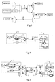
Figure 7a is a diagram showing the architecture of a solution in which the subcarrier modulated and electronic heterodyne beat-frequency demodulation is adopted according to an embodiment of the invention; -
Figure 7b is a diagram showing the architecture of a solution in which the optical detection subcarrier demodulation is adopted according to an embodiment of the invention; -
Figure 8 is a diagram showing the cascade architecture between a plurality of OLT transmitting modules and a plurality of ONUs according to an embodiment of the invention; -
Figure 9 is a flow chart showing the method for realizing the WDM-PON according to an embodiment of the invention. - The embodiments of the invention are now further illustrated in conjunction with the drawings.
- With the embodiments of the invention, a signal transmission between an OLT and a network unit in an access network may be realized As shown in
Figure 4 , a WDM-PON according to an embodiment of the invention includes: anOLT transmitting module 1 on the OLT side, theOLT transmitting module 1 being able to provide a shared optical source; anONU receiving module 6 on the ONU side; and a transmission optical fiber segment 7. TheONU receiving module 6 transmits an uplink signal by using the shared optical source provided by theOLT transmitting module 1, and receives a downlink signal. InFigure 4 , a unidirectional arrow indicates a single fiber in single direction transmission, and a bidirectional arrow indicates a single fiber dual direction transmission. The wavelength in the downlink transmission is marked above the lines, and the wavelength in the uplink transmission is marked under the lines. - The
OLT transmitting module 1 includes: a shared optical source 11 (e.g. a single longitudinal mode continuum optical source), anoptical splitter 12, anoptical multiplexer 13, amodulator 14, adivision selector 15 and anOLT receiver 16. Wherein, theoptical splitter 12 may also be a power splitter, which is adapted to split the continuous light transmitted from theoptical source 11 into two beams. One beam directly enters theoptical multiplexer 13, and the other beam passes through themodulator 14, and then enters theoptical multiplexer 13 after a transmission signal is loaded, where the other beam is multiplexed with the one beam of the continuous light that carries no signal. Then, the multiplexed light is output to the port I of a circulator. - A circulator, a device or a system that has the function of dividing and selecting may be adopted as the
division selector 15. The circulator is a device which transmits the light in a single direction. The input light enters the circulator from an input port, and is output from a second port II. Similarly, the light that enters the circulator from the second port is reflected to a third port III and outputs. - Generally, the transmission signal from the OLT to the ONU is referred to as downlink signal, and the transmission signal from the ONU to the OLT is referred to as uplink signal.
- The
ONU receiving module 6 is adapted to implement the receiving of the downlink optical signal and the transmitting of the uplink optical signal. TheONU receiving module 6 includes anoptical demultiplexer 61, anONU receiver 62, a circulator 63 and a modulator 64. Theoptical demultiplexer 61 is adapted to separate the continuous light with a wavelength of λ from the signal light with a wavelength of λ±Δλ transmitted from theOLT transmitting module 1. The signal light is transmitted to the receiving module for demodulation, and the continuous light is used as the carrier for the uplink signal. The continuous light enters the modulator 64 via port II of the circulator, loaded with the signal to be transported, sent to the transmission line via port III of the circulator, and received by the receivingmodule 16 when the continuous light returns to themodule 1. The receivingmodule 16 has the function of handling the burst mode. When an ONU of the system receives an instruction from the OLT indicating that the ONU is allowed to send data, the ONU sends data to the designated time slot in the uplink frame in a burst mode. Therefore, the optical transceiver of the ONU should also support the burst transmission mode in addition to fulfilling the requirements for a Gigabit Ethernet optical transceiver. In an ONU optical transceiver, a photodiode PIN receiver is usually adopted for continuous receiving, and an FP laser or a distributed feedback (DFB) laser may be adopted for burst transmitting. - In the above embodiment, only the case that there exists one transmitting unit on the OLT side which corresponds to one ONU is illustrated. In practice, one OLT may correspond to a plurality of ONUs. Therefore, a plurality of transmitting modules may be arranged in the OLU, and a wavelength division multiplexer/demultiplexer may be added, so as to constitute a WDM optical network. Furthermore, the OLU may be used together with the optical transceiver in the prior art as shown in
Figure 5 , wherein, compared withFigure 4 , the following components are added: an opticalsignal transmitting module 2 which has no shared optical source; a wavelength division multiplexer/demultiplexer 3, which is adapted to multiplex the downlink signals output from a plurality of optical transmitting modules on the OLT side, and demultiplex the uplink signals from the ONUs; a wavelength division multiplexer/demultiplexer 4, which is adapted to multiplex a plurality of uplink signals from the ONU side, and demultiplex the downlink signals from the OLTs; anoptical receiving module 5, which is adapted to receive the optical signal from the opticalsignal transmitting module 2 which has no shared optical source. Wherein, during the downlink transmission, the spectrum of the signal transmitted in the optical fiber segment between the wavelength division multiplexer/demultiplexer 3 and the wavelength division multiplexer/demultiplexer 4 is as shown inFigure 6(a) ; and during the downlink transmission, the spectrum of the signal between the wavelength division multiplexer/demultiplexer 4 and the receivingmodule 6 is as shown inFigure 6(b) . - The
modulator 14 is a subcarrier modulator (SCM). Therefore, compared with the central wavelength of the continuous light, the central wavelength of the output light of themodulator 14 has an offset of Δλ (the offset may be a positive offset, or may be a negative offset, and the value of the Δλ may be determined according to the wavelength resolution of the optical demultiplexer 61). A mixed light of the continuous light with a central wavelength λ and the signal light with a central wavelength λ±Δλ is output from port II of the circular 15. - Furthermore, the solution according to the embodiments of the invention in which the signal is modulated with subcarrier is different from the solution of the subcarrier modulated electronic heterodyne beat-frequency demodulation in the prior art. The solution of the subcarrier modulated electronic heterodyne beat-frequency demodulation is as shown in
Figure 7a . On the ONU side, photoelectric detection is firstly performed for the optical signal received, and the optical signal is converted into the electrical signal; the desired electrical signal is obtained by carrier multiplication demodulation, and then the information data is obtained after filtering with an electrical filter. The solution of all optical detection subcarrier demodulation is as shown inFigure 7b , which includes anoptical filter 71 and anoptical detector 72. Theoptical filter 71 allows the signal in the operating frequency band to pass, and the optical signal is converted to the electrical signal via theoptical detector 72. InFigure 7b , fc is the central frequency of the optical carrier, and f1 and f2 are subcarrier frequencies. - Furthermore, with a plurality of optical multiplexers, a large scale cascade of a plurality of OLT transmitting modules may be realized, as shown in
Figure 8 . The OLT includes a plurality of OLT transmitting modules, and each ONU includes an ONU receiving module. A one-to-one mapping is established between the OLT transmitting module and the ONU receiving module. - Furthermore, the OLT may further include a transmitting module which provides no shared optical source, and the ONU may further include a receiving module corresponding to the above transmitting module.
- A method for realizing the WDM-PON according to an embodiment of the invention is shown in
Figure 9 , which includes: - S101: Splitting the light from a same optical source into two beams in an OLT, one beam is adapted to transmit a downlink signal after modulation, and the other beam is used as an uplink carrier signal; wherein, the modulation is a subcarrier modulation.
- S102: The two beams are sent to an ONU receiving unit after optical multiplexing.
- S103: The ONU receiving module demodulates the downlink signal, and transmits an uplink signal with the uplink carrier signal; when the subcarrier modulation is adopted in S101; the ONU receiving module demodulates the modulated signal with all optical detection subcarrier demodulation.
- Additional modifications and equal substitutions, such as implementing the invention with a two-fiber bi-directional network architecture, will readily occur to those skilled in the art. Therefore, the invention in its broader aspects is not limited to the specific details and representative embodiments shown and described above. Accordingly, various modifications and variations may be made without departing from the scope of the invention.
Claims (13)
- A wavelength division multiplexing passive optical network, comprising an optical line terminal and at least one optical network unit, wherein:the optical line terminal comprises at least one optical transmitting module (1), the optical network unit comprises an optical receiving module (6), a one-to-one mapping is established between the optical transmitting module (1) and the optical receiving module (6);the optical transmitting module (1) is adapted to split a light with a wavelength of λ from the same optical source into two optical signals, a first optical signal is modulated and used as a downlink carrier signal, and a second optical signal unchanged loops back from the optical network unit, and is used as an uplink carrier signal,the optical receiving module (6) is adapted to receive the multiplexed signal comprising the modulated downlink signal and the second optical signal from the optical transmitting module (1), separate the multiplexed signal and use the second optical signal received as the uplink carrier signal to transmit the uplink signal.wherein the optical transmitting module (1) of the optical line terminal comprises: a shared optical source (11), an optical splitter (12), an optical multiplexer (13), a modulator (14), a division selector (15) and an optical receiver (16); wherein,the optical splitter (12) is adapted to split a continuous light with a wavelength of λ from the optical source into the two optical signals, the first optical signal enters the modulator (14) as the downlink carrier signal, and the second optical signal enters the optical multiplexer (13) directly;the modulator (14) is adapted to modulate a downlink signal to the first optical signal and then input a modulated downlink signal to the optical multiplexer (13), where a central wavelength of the modulated downlink signal has an offset of a preset value Δλ compared with a central wavelength of the second optical signal;the optical multiplexer (13) is adapted to multiplex the modulated downlink signal with the second optical signal, and send a multiplexed signal to the optical network unit via the division selector (15); and the optical receiver (16) is adapted to receive an uplink signal sent by the optical network unit via the division selector (15);
- The wavelength division multiplexing passive optical network according to claim 1, wherein the optical receiving module (6) of the optical network unit comprises: an optical demultiplexer (61), an optical network unit receiver (62), a division selector (63) and an uplink signal modulator (64); wherein,
the optical demultiplexer (61) is adapted to separate the uplink carrier signal from the modulated downlink signal sent by the optical transmitting module (1);
the optical network unit receiver (62) is adapted to receive the modulated downlink signal;
the division selector (63) is adapted to send the uplink carrier signal to the uplink signal modulator (64); and
the uplink signal modulator (64) is adapted to use the uplink carrier signal to modulate the uplink signal, and send a modulated uplink signal to the optical line terminal via the optical demultiplexer (61). - The wavelength division multiplexing passive optical network according to claim 2, wherein the optical network unit receiver (62) further comprises:a demodulator, adapted to demodulate the modulated downlink signal received.
- The wavelength division multiplexing passive optical network according to claim 3, wherein the demodulator is an all optical detection subcarrier demodulator or a subcarrier modulated electronic heterodyne beat-frequency demodulator.
- The wavelength division multiplexing passive optical network according to claim 4, wherein the all optical detection subcarrier demodulator comprises: an optical filter (71) and an optical detector (72),
the optical filter (71) allows an optical signal in an operating frequency band to pass, and the optical signal is converted to a electrical signal via the optical detector (72). - The wavelength division multiplexing passive optical network according to claim 1 or 2, wherein the division selector (15, 63) is a circulator.
- The wavelength division multiplexing passive optical network according to claim 1, wherein the optical line terminal further comprises another transmitting module (2) which has no shared optical source, the optical network unit further comprises another receiving module (5) corresponding to the another transmitting module (2).
- The wavelength division multiplexing passive optical network according to claim 1 or 7, wherein the network further comprises:wavelength division multiplexer/demultiplexers (3, 4), arranged on an optical line terminal side and on an optical network unit side, and adapted to perform multiplexing and demultiplexing of a downlink signal or the uplink signal respectively.
- An optical line terminal, comprising:an optical transmitting module (1), adapted to split a light with a wavelength of λ from the same optical source into two optical signals, a first optical signal is modulated and used as a downlink carrier signal, and a second optical signal unchanged loops back from an optical network unit, and is used as an uplink carrier signal; wherein the optical transmitting module (1) of the optical line terminal comprises: a shared optical source (11), an optical splitter (12), an optical multiplexer (13), a modulator (14), a division selector (15) and an optical receiver (16); wherein,the optical splitter (12) is adapted to split a continuous light with a wavelength of λ from the optical source into the two optical signals, the first optical signal enters the modulator (14) as the downlink carrier signal, and the second optical signal enters the optical multiplexer (13) directly;the modulator (14) is adapted to modulate a downlink signal to the first optical signal and then input a modulated downlink signal to the optical multiplexer (13), where a central wavelength of the modulated downlink signal has an offset of a preset value Δλ compared with a central wavelength of the second optical signal;the optical multiplexer (13) is adapted to multiplex the modulated downlink signal with the second optical signal, and send a multiplexed signal to the optical network unit via the division selector (15); andthe optical receiver (16) is adapted to receive the uplink signal sent by the optical network unit via the division selector (15).
- The optical line terminal according to claim 9, wherein the optical line terminal further comprises another transmitting module (2) that has no shared optical source.
- A method for implementing a wavelength division multiplexing passive optical network, comprising:Splitting (s101) a light with a wavelength of λ from the same optical source into two optical signals at an optical line terminal, taking a first optical signal modulated as a downlink signal after modulation, and taking a second optical signal unchanged as an uplink carrier signal, wherein, after modulation a central wavelength of the modulated first optical signal has an offset of a preset value Δλ compared with a central wavelength of the second optical signal;Multiplexing (s102) the modulated first optical signal with the second optical signal, and sending a multiplexed signal to a receiving module of an optical network unit; andReceiving (s103), by the receiving module of the optical network unit, the multiplexed signal, and separating the multiplexed signal into the first modulated optical signal and the second optical signal, sending an uplink signal with the second optical signal.
- The method for implementing a wavelength division multiplexing passive optical network according to claim 11, wherein the modulation is a subcarrier modulation.
- The method for implementing a wavelength division multiplexing passive optical network according to claim 12, wherein a subcarrier demodulation comprises an all optical detection subcarrier demodulation and a subcarrier modulated electronic heterodyne beat-frequency demodulation.
Applications Claiming Priority (2)
| Application Number | Priority Date | Filing Date | Title |
|---|---|---|---|
| CN200510131990.3A CN1983906B (en) | 2005-12-22 | 2005-12-22 | Passive light network for wave duplexing and its realization |
| PCT/CN2006/003203 WO2007071154A1 (en) | 2005-12-22 | 2006-11-28 | A wavelength division multiplexing passive optical network and its implement method |
Publications (3)
| Publication Number | Publication Date |
|---|---|
| EP1887724A1 EP1887724A1 (en) | 2008-02-13 |
| EP1887724A4 EP1887724A4 (en) | 2013-03-27 |
| EP1887724B1 true EP1887724B1 (en) | 2016-04-27 |
Family
ID=38166172
Family Applications (1)
| Application Number | Title | Priority Date | Filing Date |
|---|---|---|---|
| EP06817919.1A Active EP1887724B1 (en) | 2005-12-22 | 2006-11-28 | A wavelength division multiplexing passive optical network and its implement method |
Country Status (3)
| Country | Link |
|---|---|
| EP (1) | EP1887724B1 (en) |
| CN (2) | CN1983906B (en) |
| WO (1) | WO2007071154A1 (en) |
Families Citing this family (25)
| Publication number | Priority date | Publication date | Assignee | Title |
|---|---|---|---|---|
| CN101399618B (en) * | 2007-09-26 | 2011-06-15 | 华为技术有限公司 | Optical line terminal, passive optical network and radio frequency signal transmission method |
| CN101420285B (en) | 2007-10-25 | 2012-02-15 | 华为技术有限公司 | Optical line terminal, far-end node unit, method and system for reducing quantity of light source |
| CN101471730B (en) * | 2007-12-29 | 2013-02-13 | 上海鼎频通信技术有限公司 | Optical fiber wideband access system and optical network unit based on WDM structure |
| CN101286803B (en) * | 2008-05-30 | 2011-07-06 | 北京北方烽火科技有限公司 | Optimizing method for dual and locked mode optical fiber wireless wave division multiplexing system |
| US8934773B2 (en) * | 2008-07-31 | 2015-01-13 | Xieon Networks S.A.R.L. | Method for data processing in an optical network, optical network component and communication system |
| CN101346006B (en) * | 2008-08-19 | 2011-01-19 | 武汉长光科技有限公司 | Radio frequency passive optical network with broadband wireless and optical transmission amalgamation access |
| TWI416884B (en) * | 2008-09-04 | 2013-11-21 | Univ Nat Kaohsiung Applied Sci | Passive-optical-network transmission system capable of receiving wireless signals |
| CN101662707B (en) * | 2009-10-14 | 2013-09-11 | 烽火通信科技股份有限公司 | Method and device for sharing broadband light source in a plurality of WDM-PON systems |
| CN101702785B (en) * | 2009-10-29 | 2013-01-23 | 北京邮电大学 | Multi-wavelength passive optical network system, wavelength reusing method and optical network unit |
| CN102201860B (en) * | 2010-03-24 | 2016-07-06 | 中兴通讯股份有限公司 | Optical network unit abnormal luminescence failure isolation system and method |
| CN102131129A (en) * | 2010-04-28 | 2011-07-20 | 华为技术有限公司 | Method, device and system for receiving uplink signal in passive optical network (PON) |
| CN102256186A (en) * | 2010-05-20 | 2011-11-23 | 宁波高新区晓圆科技有限公司 | Optical module of novel passive optical network |
| CN103404057B (en) * | 2010-06-22 | 2016-08-03 | 技术研究及发展基金公司 | Optical network unit, optical access network and the method being used for exchanging information |
| CN101997769A (en) * | 2010-07-20 | 2011-03-30 | 复旦大学 | OFDM multi-sideband multi-subcarrier distribution technology based passive optical network system |
| CN102761795B (en) * | 2012-07-10 | 2015-08-12 | 青岛海信宽带多媒体技术有限公司 | EPON and light fill system thereof |
| CN102820945B (en) * | 2012-08-24 | 2015-09-30 | 武汉邮电科学研究院 | Based on passive optical network and the implementation method of Nyquist wavelength division multiplexing |
| CN103152657B (en) * | 2013-03-21 | 2015-05-27 | 上海交通大学 | Wave division multiplexing orthogonal frequency division multiplexing passive optical network (WDM-OFDM-PON) system based on shared transmitter energy-saving scheme |
| WO2014176722A1 (en) * | 2013-04-28 | 2014-11-06 | 华为技术有限公司 | Optical device, and wireless signal transmitting apparatus and system |
| CN105680901B (en) * | 2014-11-19 | 2020-04-10 | 中兴通讯股份有限公司 | Device and method for realizing carrier frequency signal combining distribution |
| WO2018137154A1 (en) * | 2017-01-24 | 2018-08-02 | 华为技术有限公司 | Communication method, device and system for passive optical network (pon) |
| CN110798265A (en) * | 2018-08-01 | 2020-02-14 | 中兴通讯股份有限公司 | Optical module, method, device and system for obtaining optical signal and storage medium |
| CN109379136B (en) * | 2018-11-26 | 2021-03-23 | 瑞斯康达科技发展股份有限公司 | Optical fiber transmission system and information transmission method |
| CN110798280B (en) * | 2019-11-08 | 2022-02-18 | 成都优博创通信技术股份有限公司 | Wavelength locking method and device, optical module and wavelength division multiplexing optical network |
| CN113872692B (en) * | 2021-09-30 | 2023-12-08 | 中国科学院半导体研究所 | Terminal equipment, forwarding equipment and method and device for constructing optical communication network |
| CN115426010B (en) * | 2022-08-05 | 2024-02-23 | 中国电信股份有限公司 | 5G MIMO signal transmission system and method |
Family Cites Families (7)
| Publication number | Priority date | Publication date | Assignee | Title |
|---|---|---|---|---|
| US6118565A (en) * | 1997-09-30 | 2000-09-12 | Lucent Technologies Inc. | Coherent optical communication system |
| JP2000196536A (en) | 1998-12-28 | 2000-07-14 | Nippon Telegr & Teleph Corp <Ntt> | Wavelength multiplexed two-way optical transmission system |
| KR100630049B1 (en) * | 2002-03-21 | 2006-09-27 | 삼성전자주식회사 | Wavelength division multiplexing passive optical network system |
| CN100377514C (en) * | 2003-02-19 | 2008-03-26 | 华为技术有限公司 | Method and system for increasing spectrum utilization factor in wavelength division multiplexing system |
| US7389048B2 (en) * | 2003-06-18 | 2008-06-17 | Nippon Telegraph And Telephone Corporation | Optical wavelength-division multiple access system and optical network unit |
| WO2005013526A1 (en) * | 2003-07-29 | 2005-02-10 | University Of Melbourne | Optical network untilising spread spectrum transmission |
| KR100609698B1 (en) * | 2004-06-09 | 2006-08-08 | 한국전자통신연구원 | Wavelength division multiplexing passive optical network and optical source generating method |
-
2005
- 2005-12-22 CN CN200510131990.3A patent/CN1983906B/en active Active
-
2006
- 2006-11-28 EP EP06817919.1A patent/EP1887724B1/en active Active
- 2006-11-28 WO PCT/CN2006/003203 patent/WO2007071154A1/en active Application Filing
- 2006-11-28 CN CN200680012045.4A patent/CN101160768A/en active Pending
Also Published As
| Publication number | Publication date |
|---|---|
| CN1983906B (en) | 2010-10-27 |
| CN1983906A (en) | 2007-06-20 |
| WO2007071154A1 (en) | 2007-06-28 |
| EP1887724A4 (en) | 2013-03-27 |
| EP1887724A1 (en) | 2008-02-13 |
| CN101160768A (en) | 2008-04-09 |
Similar Documents
| Publication | Publication Date | Title |
|---|---|---|
| EP1887724B1 (en) | A wavelength division multiplexing passive optical network and its implement method | |
| Shea et al. | Long-reach optical access technologies | |
| Song et al. | Long-reach optical access networks: A survey of research challenges, demonstrations, and bandwidth assignment mechanisms | |
| KR100875922B1 (en) | Downlink optical transmitter and method using wavelength independent light source in WDM passive optical subscriber network, and optical line termination system using the same | |
| KR100819034B1 (en) | Passive optical networkPON based on reflective semiconductor optical amplifierRSOA | |
| CN101114885B (en) | Wavelength-division and time division multiplex mixing passive optical network system, terminal and signal transmission method | |
| KR100921797B1 (en) | Wavelength Division Multiplexing - Passive Optical Network system | |
| US8055133B2 (en) | TDM/WDMA passive optical network device | |
| EP2314003B1 (en) | Method for data processing in an optical network, optical network component and communication system | |
| US20130272707A1 (en) | Optical network | |
| CN102724012B (en) | Light-source-shared WDM-PON (wavelength division multiplexed passive optical network) system based on suppressed carrier modulation technique | |
| US20080131125A1 (en) | Loopback-type wavelength division multiplexing passive optical network system | |
| EP2285019B1 (en) | Optical communication system, apparatus and method | |
| CN101127571A (en) | A public light source shared by WDM-PON system and method for light source sharing | |
| US20100021164A1 (en) | Wdm pon rf/video broadcast overlay | |
| WO2007143931A1 (en) | A wavelena wavelength division multiplexing passive optical network | |
| CN101662707B (en) | Method and device for sharing broadband light source in a plurality of WDM-PON systems | |
| KR100678024B1 (en) | Hybrid passive optical network using wireless communication | |
| US9590734B2 (en) | Method for data processing in an optical network component and optical network component | |
| KR100754601B1 (en) | Hybrid passive optical network | |
| CN202004922U (en) | Passive optical network system on wavelength division multiplexing | |
| EP1953941B1 (en) | WDM laser sources for PON | |
| CN101043287B (en) | Transmission method and system for wavelength-division multiplexed passive optical network | |
| WO2007135407A1 (en) | A method and apparatus for combining electrical signals | |
| JP3615476B2 (en) | Optical access system, access node device, and user node device |
Legal Events
| Date | Code | Title | Description |
|---|---|---|---|
| PUAI | Public reference made under article 153(3) epc to a published international application that has entered the european phase |
Free format text: ORIGINAL CODE: 0009012 |
|
| 17P | Request for examination filed |
Effective date: 20071212 |
|
| AK | Designated contracting states |
Kind code of ref document: A1 Designated state(s): AT BE BG CH CY CZ DE DK EE ES FI FR GB GR HU IE IS IT LI LT LU LV MC NL PL PT RO SE SI SK TR |
|
| DAX | Request for extension of the european patent (deleted) | ||
| DAX | Request for extension of the european patent (deleted) | ||
| A4 | Supplementary search report drawn up and despatched |
Effective date: 20130221 |
|
| RIC1 | Information provided on ipc code assigned before grant |
Ipc: H04J 14/02 20060101AFI20130215BHEP |
|
| 17Q | First examination report despatched |
Effective date: 20130902 |
|
| GRAP | Despatch of communication of intention to grant a patent |
Free format text: ORIGINAL CODE: EPIDOSNIGR1 |
|
| INTG | Intention to grant announced |
Effective date: 20151106 |
|
| GRAS | Grant fee paid |
Free format text: ORIGINAL CODE: EPIDOSNIGR3 |
|
| GRAA | (expected) grant |
Free format text: ORIGINAL CODE: 0009210 |
|
| AK | Designated contracting states |
Kind code of ref document: B1 Designated state(s): AT BE BG CH CY CZ DE DK EE ES FI FR GB GR HU IE IS IT LI LT LU LV MC NL PL PT RO SE SI SK TR |
|
| REG | Reference to a national code |
Ref country code: GB Ref legal event code: FG4D |
|
| REG | Reference to a national code |
Ref country code: CH Ref legal event code: EP |
|
| REG | Reference to a national code |
Ref country code: AT Ref legal event code: REF Ref document number: 795809 Country of ref document: AT Kind code of ref document: T Effective date: 20160515 |
|
| REG | Reference to a national code |
Ref country code: IE Ref legal event code: FG4D |
|
| REG | Reference to a national code |
Ref country code: DE Ref legal event code: R096 Ref document number: 602006048895 Country of ref document: DE |
|
| REG | Reference to a national code |
Ref country code: LT Ref legal event code: MG4D |
|
| REG | Reference to a national code |
Ref country code: NL Ref legal event code: MP Effective date: 20160427 |
|
| REG | Reference to a national code |
Ref country code: AT Ref legal event code: MK05 Ref document number: 795809 Country of ref document: AT Kind code of ref document: T Effective date: 20160427 |
|
| PG25 | Lapsed in a contracting state [announced via postgrant information from national office to epo] |
Ref country code: NL Free format text: LAPSE BECAUSE OF FAILURE TO SUBMIT A TRANSLATION OF THE DESCRIPTION OR TO PAY THE FEE WITHIN THE PRESCRIBED TIME-LIMIT Effective date: 20160427 |
|
| REG | Reference to a national code |
Ref country code: FR Ref legal event code: PLFP Year of fee payment: 11 |
|
| PG25 | Lapsed in a contracting state [announced via postgrant information from national office to epo] |
Ref country code: PL Free format text: LAPSE BECAUSE OF FAILURE TO SUBMIT A TRANSLATION OF THE DESCRIPTION OR TO PAY THE FEE WITHIN THE PRESCRIBED TIME-LIMIT Effective date: 20160427 Ref country code: LT Free format text: LAPSE BECAUSE OF FAILURE TO SUBMIT A TRANSLATION OF THE DESCRIPTION OR TO PAY THE FEE WITHIN THE PRESCRIBED TIME-LIMIT Effective date: 20160427 Ref country code: FI Free format text: LAPSE BECAUSE OF FAILURE TO SUBMIT A TRANSLATION OF THE DESCRIPTION OR TO PAY THE FEE WITHIN THE PRESCRIBED TIME-LIMIT Effective date: 20160427 |
|
| PG25 | Lapsed in a contracting state [announced via postgrant information from national office to epo] |
Ref country code: GR Free format text: LAPSE BECAUSE OF FAILURE TO SUBMIT A TRANSLATION OF THE DESCRIPTION OR TO PAY THE FEE WITHIN THE PRESCRIBED TIME-LIMIT Effective date: 20160728 Ref country code: PT Free format text: LAPSE BECAUSE OF FAILURE TO SUBMIT A TRANSLATION OF THE DESCRIPTION OR TO PAY THE FEE WITHIN THE PRESCRIBED TIME-LIMIT Effective date: 20160829 Ref country code: LV Free format text: LAPSE BECAUSE OF FAILURE TO SUBMIT A TRANSLATION OF THE DESCRIPTION OR TO PAY THE FEE WITHIN THE PRESCRIBED TIME-LIMIT Effective date: 20160427 Ref country code: AT Free format text: LAPSE BECAUSE OF FAILURE TO SUBMIT A TRANSLATION OF THE DESCRIPTION OR TO PAY THE FEE WITHIN THE PRESCRIBED TIME-LIMIT Effective date: 20160427 Ref country code: ES Free format text: LAPSE BECAUSE OF FAILURE TO SUBMIT A TRANSLATION OF THE DESCRIPTION OR TO PAY THE FEE WITHIN THE PRESCRIBED TIME-LIMIT Effective date: 20160427 Ref country code: SE Free format text: LAPSE BECAUSE OF FAILURE TO SUBMIT A TRANSLATION OF THE DESCRIPTION OR TO PAY THE FEE WITHIN THE PRESCRIBED TIME-LIMIT Effective date: 20160427 |
|
| PG25 | Lapsed in a contracting state [announced via postgrant information from national office to epo] |
Ref country code: BE Free format text: LAPSE BECAUSE OF FAILURE TO SUBMIT A TRANSLATION OF THE DESCRIPTION OR TO PAY THE FEE WITHIN THE PRESCRIBED TIME-LIMIT Effective date: 20160427 Ref country code: IT Free format text: LAPSE BECAUSE OF FAILURE TO SUBMIT A TRANSLATION OF THE DESCRIPTION OR TO PAY THE FEE WITHIN THE PRESCRIBED TIME-LIMIT Effective date: 20160427 |
|
| REG | Reference to a national code |
Ref country code: DE Ref legal event code: R097 Ref document number: 602006048895 Country of ref document: DE |
|
| PG25 | Lapsed in a contracting state [announced via postgrant information from national office to epo] |
Ref country code: DK Free format text: LAPSE BECAUSE OF FAILURE TO SUBMIT A TRANSLATION OF THE DESCRIPTION OR TO PAY THE FEE WITHIN THE PRESCRIBED TIME-LIMIT Effective date: 20160427 Ref country code: CZ Free format text: LAPSE BECAUSE OF FAILURE TO SUBMIT A TRANSLATION OF THE DESCRIPTION OR TO PAY THE FEE WITHIN THE PRESCRIBED TIME-LIMIT Effective date: 20160427 Ref country code: SK Free format text: LAPSE BECAUSE OF FAILURE TO SUBMIT A TRANSLATION OF THE DESCRIPTION OR TO PAY THE FEE WITHIN THE PRESCRIBED TIME-LIMIT Effective date: 20160427 Ref country code: EE Free format text: LAPSE BECAUSE OF FAILURE TO SUBMIT A TRANSLATION OF THE DESCRIPTION OR TO PAY THE FEE WITHIN THE PRESCRIBED TIME-LIMIT Effective date: 20160427 Ref country code: RO Free format text: LAPSE BECAUSE OF FAILURE TO SUBMIT A TRANSLATION OF THE DESCRIPTION OR TO PAY THE FEE WITHIN THE PRESCRIBED TIME-LIMIT Effective date: 20160427 |
|
| PLBE | No opposition filed within time limit |
Free format text: ORIGINAL CODE: 0009261 |
|
| STAA | Information on the status of an ep patent application or granted ep patent |
Free format text: STATUS: NO OPPOSITION FILED WITHIN TIME LIMIT |
|
| 26N | No opposition filed |
Effective date: 20170130 |
|
| PG25 | Lapsed in a contracting state [announced via postgrant information from national office to epo] |
Ref country code: SI Free format text: LAPSE BECAUSE OF FAILURE TO SUBMIT A TRANSLATION OF THE DESCRIPTION OR TO PAY THE FEE WITHIN THE PRESCRIBED TIME-LIMIT Effective date: 20160427 |
|
| REG | Reference to a national code |
Ref country code: CH Ref legal event code: PL |
|
| PG25 | Lapsed in a contracting state [announced via postgrant information from national office to epo] |
Ref country code: LI Free format text: LAPSE BECAUSE OF NON-PAYMENT OF DUE FEES Effective date: 20161130 Ref country code: CH Free format text: LAPSE BECAUSE OF NON-PAYMENT OF DUE FEES Effective date: 20161130 |
|
| REG | Reference to a national code |
Ref country code: IE Ref legal event code: MM4A |
|
| PG25 | Lapsed in a contracting state [announced via postgrant information from national office to epo] |
Ref country code: LU Free format text: LAPSE BECAUSE OF NON-PAYMENT OF DUE FEES Effective date: 20161130 |
|
| REG | Reference to a national code |
Ref country code: FR Ref legal event code: PLFP Year of fee payment: 12 |
|
| PG25 | Lapsed in a contracting state [announced via postgrant information from national office to epo] |
Ref country code: IE Free format text: LAPSE BECAUSE OF NON-PAYMENT OF DUE FEES Effective date: 20161128 |
|
| PG25 | Lapsed in a contracting state [announced via postgrant information from national office to epo] |
Ref country code: HU Free format text: LAPSE BECAUSE OF FAILURE TO SUBMIT A TRANSLATION OF THE DESCRIPTION OR TO PAY THE FEE WITHIN THE PRESCRIBED TIME-LIMIT; INVALID AB INITIO Effective date: 20061128 Ref country code: CY Free format text: LAPSE BECAUSE OF FAILURE TO SUBMIT A TRANSLATION OF THE DESCRIPTION OR TO PAY THE FEE WITHIN THE PRESCRIBED TIME-LIMIT Effective date: 20160427 |
|
| PG25 | Lapsed in a contracting state [announced via postgrant information from national office to epo] |
Ref country code: MC Free format text: LAPSE BECAUSE OF FAILURE TO SUBMIT A TRANSLATION OF THE DESCRIPTION OR TO PAY THE FEE WITHIN THE PRESCRIBED TIME-LIMIT Effective date: 20160427 Ref country code: IS Free format text: LAPSE BECAUSE OF FAILURE TO SUBMIT A TRANSLATION OF THE DESCRIPTION OR TO PAY THE FEE WITHIN THE PRESCRIBED TIME-LIMIT Effective date: 20160427 Ref country code: TR Free format text: LAPSE BECAUSE OF FAILURE TO SUBMIT A TRANSLATION OF THE DESCRIPTION OR TO PAY THE FEE WITHIN THE PRESCRIBED TIME-LIMIT Effective date: 20160427 |
|
| PG25 | Lapsed in a contracting state [announced via postgrant information from national office to epo] |
Ref country code: BG Free format text: LAPSE BECAUSE OF FAILURE TO SUBMIT A TRANSLATION OF THE DESCRIPTION OR TO PAY THE FEE WITHIN THE PRESCRIBED TIME-LIMIT Effective date: 20160427 |
|
| REG | Reference to a national code |
Ref country code: FR Ref legal event code: PLFP Year of fee payment: 13 |
|
| PGFP | Annual fee paid to national office [announced via postgrant information from national office to epo] |
Ref country code: FR Payment date: 20230929 Year of fee payment: 18 |
|
| PGFP | Annual fee paid to national office [announced via postgrant information from national office to epo] |
Ref country code: GB Payment date: 20231006 Year of fee payment: 18 |
|
| PGFP | Annual fee paid to national office [announced via postgrant information from national office to epo] |
Ref country code: DE Payment date: 20231003 Year of fee payment: 18 |