EP1887699B1 - Beschleunigtes dynamisches N-Kanal Register - Google Patents
Beschleunigtes dynamisches N-Kanal Register Download PDFInfo
- Publication number
- EP1887699B1 EP1887699B1 EP06254807A EP06254807A EP1887699B1 EP 1887699 B1 EP1887699 B1 EP 1887699B1 EP 06254807 A EP06254807 A EP 06254807A EP 06254807 A EP06254807 A EP 06254807A EP 1887699 B1 EP1887699 B1 EP 1887699B1
- Authority
- EP
- European Patent Office
- Prior art keywords
- node
- signal
- low
- output
- coupled
- Prior art date
- Legal status (The legal status is an assumption and is not a legal conclusion. Google has not performed a legal analysis and makes no representation as to the accuracy of the status listed.)
- Active
Links
Images




Classifications
-
- H—ELECTRICITY
- H03—ELECTRONIC CIRCUITRY
- H03K—PULSE TECHNIQUE
- H03K19/00—Logic circuits, i.e. having at least two inputs acting on one output; Inverting circuits
- H03K19/02—Logic circuits, i.e. having at least two inputs acting on one output; Inverting circuits using specified components
- H03K19/08—Logic circuits, i.e. having at least two inputs acting on one output; Inverting circuits using specified components using semiconductor devices
- H03K19/094—Logic circuits, i.e. having at least two inputs acting on one output; Inverting circuits using specified components using semiconductor devices using field-effect transistors
- H03K19/096—Synchronous circuits, i.e. using clock signals
- H03K19/0963—Synchronous circuits, i.e. using clock signals using transistors of complementary type
Definitions
- the present invention relates to dynamic logic and register functions, and more particularly to an N-domino output register with accelerated discharge and non-discharge paths for registering the outputs of complex logic circuits where speed and size are important factors.
- Register logic is employed to hold the outputs of devices and circuits for a period of time so that these outputs can be received by other devices and circuits.
- registers are used to latch and hold the outputs of a given pipeline stage for a period of one clock cycle so that input circuits in a subsequent stage can receive the outputs during that period while the given pipeline stage is concurrently generating new outputs.
- registers to hold the inputs to and the outputs from the evaluation circuits.
- these registers have associated setup and hold time requirements, both of which constrain the evaluation circuits in the preceding stage.
- registers have corresponding data-to-output time characteristics, which constrain the evaluation circuits in subsequent stages.
- the "speed" of a register is typically judged in terms of its data-to-output time, that is, the sum of its setup time and clock-to-output time.
- Preceding and following a logical evaluation circuit with traditional register circuits introduces delays into a pipeline system whose cumulative effect results in significantly slower operating speeds. More specifically, one notable source of these delays is the data-to-output time requirements that must be satisfied by logical evaluation circuits in order to ensure stable registered outputs. It is desired to reduce these delays to provide additional time in each stage and to thereby increase overall speed of the pipeline system.
- Both the N-channel and P-channel versions of the non-inverting domino register provide significant speed advantages when data inputs cause the non-inverting register to discharge a pre-charged node or to charge a pre-discharged node therein when clocked.
- the present inventors have noted as well a desire to decrease clock-to-output time for both P-channel and N-channel versions of the non-inverting domino register when data inputs are such that the pre-charged node does not discharge or the pre-discharged node does not charge when clocked.
- a non-inverting dynamic register includes a domino stage, a mux, and an output stage.
- the domino stage evaluates a logic function based on at least one input data signal and a pulsed clock signal, where the domino stage pre-charges a pre-charged node high when the pulsed clock signal is low and opens an evaluation window when the pulsed clock signal goes high, and pulls the pre-charged node low if it evaluates, and keeps the pre-charged node high if it fails to evaluate.
- the mux is coupled to the domino stage. The mux is responsive to the pulsed clock signal and the pre-charged node.
- the mux pulls a feedback node low if the pre-charged node goes low during the evaluation window, and pulls the feedback node high if the pre-charged node is high during the evaluation window.
- the mux receives a delayed feedback signal having the same state as the feedback node, but lagging in time, where the delayed feedback signal is selected when the pulsed clock signal goes low.
- the output stage is coupled to the pre-charged node and the feedback node. The output stage provides an output signal based on states of the pre-charged and the feedback nodes.
- a method of registering a logic function and generating a non-inverted output includes pre-charging a first node high while a pulsed clock signal is low; evaluating a logic function to control the state of the first node when the pulsed clock signal goes high (where the evaluation comprises pulling the first node low when the logic function evaluates and keeping the first node high when the logic function fails to evaluate), first controlling the state of a second node with a first delayed state of the first node when the pulsed clock signal goes high (where the first controlling comprises first selecting the first delayed state of the first node as an output of a mux, wherein the output is coupled to the second node) second controlling the state of the second node with a second delayed state of the second node when the pulsed clock signal goes low; and determining the state of an output node based on the states of the first and second nodes.
- FIGURE 1 is a schematic diagram of a non-inverting N-domino register implemented according to a prior disclosure which is incorporated by reference;
- FIGURE 2 is a timing diagram illustrating operation of the non-inverting N-domino register of FIGURES 1 , 3-4 , and 5 ;
- FIGURE 3 is a schematic diagram of a non-inverting N-domino register implemented according to an alternative embodiment of the register of FIGURE 1 ;
- FIGURE 4 is a schematic diagram of another non-inverting N-domino register exhibiting an improved storage stage
- FIGURE 5 is a schematic diagram of a non-inverting N-domino register employing the improved storage stage and implemented according to an alternative embodiment of the register of FIGURE 4 ;
- FIGURE 6 is a timing diagram illustrating operation of the non-inverting N-domino registers of FIGURES 1 , 3-4 , and 5 according to a pulsed clock embodiment that is preferred to minimize hold time;
- FIGURE 7 is a timing diagram illustrating operation of a non-inverting N-domino latch embodiment that employs the circuits of FIGURES 1 , 3-4 , and 5 ;
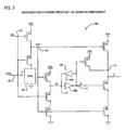
- FIGURE 8 is a schematic diagram of a non-inverting N-domino register according to an exemplary embodiment of the present invention which exhibits an accelerated discharge path;
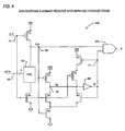
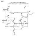
- FIGURE 9 is a schematic diagram of a non-inverting N-domino register according to a hard pull-up embodiment of the present invention which exhibits an accelerated non-discharge path;
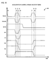
- FIGURE 10 is a timing diagram illustrating operation of the non-inverting N-domino registers of FIGURES 8-9 .
- the inventors of the present application have recognized the need for providing registered outputs for logic circuits in which speed, size and stability are critical factors, which are flexible with regard to the evaluation logic, which may be used in high leakage or high noise environments, and which moreover exhibit accelerated clock-to-output times for specified data input states. They have has therefore developed non-inverting N-domino registers that have a faster data-to-output time than that which has heretofore been provided without compromising the stability of the output, that are flexible with regard to the evaluation logic implementation, and that may be used in a high leakage or high noise environment, as will be further described below with respect to FIGURES 1-10 .
- a non-inverting N-domino register When employed in a pipeline architecture that relies heavily on registers and dynamic logic to transfer data from stage to stage, a non-inverting N-domino register according to embodiments of the present invention enables overall device operating speed to be significantly increased. Consequently, the overall device may be implemented using faster and smaller devices in a high leakage or high noise process without compromising speed.
- FIGURE 1 is a schematic diagram of a non-inverting N-domino register 100 implemented as is disclosed in U.S. Patent Application Publication No. 2005/0127952A1 .
- the non-inverting domino register 100 includes a logic evaluation input stage, or domino stage, which consists of stacked P-channel and N-channel devices P1 and N2 and evaluation logic 104.
- the P1 and N2 devices are a complementary pair of evaluation devices coupled on either side of evaluation logic 104 in the stack.
- the evaluation logic 104 may be as simple as a single N-channel device or may be significantly more complex for evaluation any desired logic function.
- the source of P1 is coupled to a voltage source VDD and its drain is coupled to node 105 providing a pre-charge signal TOP.
- the evaluation logic 104 is coupled between node 105 and the drain of N2, having its source coupled to ground.
- a clock signal CLK is provided via node 101 to the gates of P1 and N2.
- a set of N nodes 103 provide N input data signals DATA to the evaluation logic 104, where N is any positive integer.
- the domino stage of the non-inverting N-domino register 100 is followed by a storage stage which includes devices P2, N3, and N4 and a weak keeper circuit 109.
- the devices P2, N3, and N4 may be considered as a "write stage" and the keeper circuit 109 as a keeper stage within the storage stage.
- Node 101 is coupled to the gate of N3 and node 105 is coupled to the gates of P2 and N4.
- the source of P2 is coupled to VDD and its drain is coupled to a first intermediate output node 107 providing a first intermediate output signal QII.
- Node 107 is coupled to the drain of N3, to the input of an inverter 109A and to the output of another inverter 109B.
- the output of the inverter 109A is coupled to a second intermediate output node 111 providing a second intermediate output signal QI, which is coupled to the input of the inverter 109B.
- the inverters 109A and 109B are cross-coupled between nodes 107 and 111 and collectively form the weak keeper circuit 109.
- the source of N3 is coupled to the drain of N4, which has its source coupled to ground.
- the storage stage of the non-inverting domino register 100 is followed by an additional output stage, which includes P-channel devices P3 and P4 and N-channel devices N5 and N6.
- Node 105 is coupled to the gates of P4 and N6, and node 111 is coupled to the gates of P3 and N5.
- the sources of P3 and P4 are coupled to VDD and their drains are coupled together at an output node 113 providing an output signal Q.
- Output node 113 is coupled to the drain of N5, which has its source coupled to the drain of N6, which has its source coupled to ground.
- the P-channel devices generally operate as pull-up devices and the N-channel devices generally operate as pull-down devices.
- FIGURE 2 is a timing diagram illustrating operation of the non-inverting N-domino register 100, in which the CLK, DATA N , TOP, QII, QI and Q signals are plotted versus time. For clarity, the relative transitions times are estimated and delays are ignored.
- the DATAN signal is shown as a single signal representing the collective set of N DATA signals. The DATAN signal is shown asserted high for the case where the collective state of the data signals causes the evaluation logic 104 to "evaluate,” thereby pulling the pre-charge signal TOP low, and is shown asserted low for the case where the evaluation logic 104 fails to evaluate, which keeps the pre-charge signal TOP high.
- the evaluation logic 104 when the evaluation logic 104 evaluates, it causes signal TOP to transition from its pre-charged high state to a low state. When the evaluation logic "fails to evaluate,” TOP remains at its pre-charged high state. In other words, when the evaluation logic causes TOP to discharge, the level of signal TOP transitions from its pre-charged high state to a logic low level. When TOP remains at its pre-charged high logic level due to the evaluation logic 104 failing to evaluate, such is referred to as a "non-discharge" event.
- the domino stage pre-charges the TOP signal high.
- the TOP signal is pre-charged high in preparation for evaluation of the DATAN signal by the evaluation logic 104 upon the rising edge of CLK, where the DATA N signal is initially high.
- the pre-charged TOP signal turns on N4 and N6.
- the QII signal remains at its former state (shown initially in a low logic state) and is held there by the keeper circuit 109.
- the QI signal is initially high turning on N5, so that the Q output signal is initially pulled low via the N5 and N6 devices.
- the CLK signal goes high, which causes the TOP signal to discharge to a logic low level since the DATA N signal is high.
- N2 is turned on and the evaluation logic 104 pulls TOP low via N2 to ground.
- the QII signal is pulled high via P2 and the output signal Q is pulled high via P4.
- the QII and Q signals are both pulled high at about the same time T1, and the QI signal is pulled low by the inverter 109A.
- the inverted state of the QI signal at the output of the keeper circuit 109 drives the devices P3 and N5. When QI is high, P3 is off and N5 is on; and when QI is low, P3 is on and N5 is off.
- the TOP signal is once again pre-charged high.
- P2 and N3 are turned off so that node 107 is not driven to either state.
- the respective states of the QII and QI signals remain unchanged, however, via operation of the keeper circuit 109, so that the Q and QII signals remain high and the QI signal remains low throughout the remainder of the half cycle of CLK.
- the DATAN signal is shown going low at time T3 while the CLK signal is still low, and the CLK signal is next asserted high at time T4 while the DATAN signal is low.
- the evaluation logic 104 fails to evaluate, so that TOP remains high (i.e., a "non-discharge") while DATA N is low and CLK is high.
- the CLK and TOP signals turn on devices N3 and N4, respectively, so that the QII signal is asserted low at about time T4, and the QI signal is consequently pulled high by the inverter 109A.
- the TOP signal being high keeps N6 on.
- the QI signal turns N5 on and P3 off, so that the Q signal is pulled low via N5 and N6.
- the CLK signal next goes low at time T5 pulling TOP high again.
- the respective states of the QII and QI signals remain unchanged via operation of the keeper circuit 109.
- the Q signal remains low throughout the remainder of the cycle of CLK since QI keeps N5 on and TOP keeps N6 on.
- the output signal Q transitions from low to high relatively quickly in response to a rising edge of the CLK signal when the evaluation logic 104 discharges the TOP signal to a low level. There is a delay through devices N2 and P4 (i.e., the discharge path) causing the output transition.
- the output signal Q transitions from high to low after a delay through devices N3, N5, and the inverter 109A (i.e., the non-discharge path) in response to a rising edge of the CLK signal when the evaluation logic 104 fails to evaluate, leaving the TOP signal high.
- the delay through the inverter 109A is minimized by being implemented as a relatively small device (with minimal capacitance) since it does not need to have the size nor perform the function of a buffer.
- the delay can be minimized by employing ratioed logic (i.e., large P device and small N device) for the inverter 109A.
- ratioed logic i.e., large P device and small N device
- transitions of the output signal Q of the non-inverting N-domino register 100 are very fast in response to transitions of the CLK signal. If a non-inverting output is necessary or otherwise desired, the non-inverting N-domino register 100 provides superior data-to-output speed compared to conventional designs among other benefits and advantages.
- the non-inverting N-domino register 100 may be converted to an inverting N-domino register simply by adding an output inverter/buffer (not shown).
- one embodiment of the present invention employs ratioed P and N devices to configure the evaluation logic 104.
- strong N devices and weak P devices are employed, resulting in faster operation.
- the AND and OR logic circuits were exemplary only and were provided to illustrate that the evaluation logic 104 may be any complex logical evaluation circuit as appreciated by those having ordinary skill in the art.
- a possible limitation of the inverting N-domino register 100 is that it is not particularly flexible with respect to the evaluation logic 104, which typically had to be implemented as N-channel logic. N-channel logic, in some configurations, does not provide optimal levels of input noise margin.
- FIGURE 3 is a schematic diagram of a non-inverting N-domino register 300 implemented according to an alternative embodiment of the register of FIGURE 1 , and is also disclosed in U.S. Patent Application Publication Serial No. 2005/0127952A1 .
- the non-inverting N-domino register 300 is substantially similar to the non-inverting N-domino register 100 of FIGURE 1 , except that the logic evaluation input stage, or domino stage, comprising the stacked P-channel and N-channel devices P1 and N2 and evaluation logic 104, is reordered and the evaluation logic 104 is replaced with evaluation logic 301.
- the P1 and N2 devices are a complementary pair of evaluation devices coupled together at the node 105 providing the TOP signal.
- the drain of N2 is coupled to node 105 and its source is coupled to the top or upper end of the evaluation logic 301.
- the lower or bottom end of the evaluation logic 301 is coupled to ground.
- the evaluation logic 301 is located below the P1/N2 stack as opposed to being coupled between P1 and N2. Operation is substantially similar to the non-inverting N-domino register 100 of FIGURE 1 and the timing diagram of FIGURE 2 remains equally valid for the non-inverting domino register 300 of FIGURE 3 .
- the evaluation logic 301 could be configured in substantially the same manner as the evaluation logic 104. As understood by those skilled in the art, however, the evaluation logic 301 may alternatively be embodied using complementary metal-oxide semiconductor (CMOS) logic rather than N-channel logic, where again, the timing diagram of FIGURE 2 remains valid.
- CMOS logic provides significantly better input level noise margin over N-channel logic so that the non-inverting N-domino register 300 provides significantly better input level noise margin over the non-inverting N-domino register 100 when using CMOS logic in the domino stage.
- the non-inverting N-domino registers 100 and 300 both experience leakage effects when embodied in a high leakage or high noise process, such as 90 nm SOI and the like. Scaling circuits down to 90 nm introduces issues related to leakage. Scaled processes exhibit higher leakage because channel lengths are shorter. Consequently, in order to write a new state to node 107 of the storage stage for either of the registers 100 and 300, a weak device must be overcome within the feedback inverter (e.g., within the inverter 109B, a weak P-channel device to change to a low state and a weak N-channel device to change to a high state). The cost of overcoming a device is speed and current. In addition, in processes in which there is either high leakage or high noise, the weak N and P devices within the feedback inverter 109B must be made larger in order to maintain the state of the output node in the presence of leakage or noise.
- the storage node 107 (signal QII) is isolated from the input stage when CLK is low. There is nothing driving the QII signal except the keeper feedback inverter 109B, which includes internal weak N and P devices (not shown). Yet, because of increased leakage associated with a scaled process, a larger amount of leakage current flows through the P2 and N3 devices. So, the N and P devices in the inverter 109B have to be large enough to overcome that leakage. For instance, if the QII signal is high, leakage occurs to ground through the N3 and N4 devices, so that the P device within the inverter 109B has to be large enough to supply enough current to overcome that leakage to keep the QII signal high.
- FIGURE 4 is a schematic diagram of another non-inverting N-domino register 400 exhibiting and improved storage stage and employing an improved keeper circuit.
- the non-inverting N-domino register 400 includes an input domino stage followed by a storage stage and an output stage.
- the domino stage and the initial portion of the storage stage of the register 400 are similar to those of the register 100.
- the keeper circuit of the register 400 is modified to improve performance by eliminating the need to overcome devices and reduce cost in terms of speed and current.
- the domino stage includes stacked P-channel and N-channel devices P1 and N2 and evaluation logic 104.
- the P1 and N2 devices are a complementary pair of evaluation devices coupled on either side of evaluation logic 104 between the voltage source VDD and ground.
- the source of P1 is coupled to VDD and its drain is coupled to node 105 providing the TOP signal.
- the evaluation logic 104 is coupled between node 105 and the drain of N2 and the source of N2 is coupled to ground.
- the input clock signal CLK is provided via node 101 to the gates of P1, N2 and N3.
- a set of N nodes 103 provide N input data signals DATA to the evaluation logic 104.
- the node 105 providing the TOP signal is coupled to the gates of devices P2 and N4.
- the initial portion of the storage stage is substantially the same write stage including the stacked devices P2, N3 and N4.
- the source of P2 is coupled to VDD and its drain is coupled to node 107 developing the first intermediate output signal QII.
- the drain of N3 is coupled to node 107 and its source is coupled to the drain of N4, having its source coupled to ground.
- the storage stage of the non-inverting N-domino register 400 has the write stage including devices P3, P4, and N5 and a keeper stage including devices P3, P4, N3, and an inverter 401.
- the storage stage is followed by an output stage, which comprises a two-input NAND gate 403 in the embodiment illustrated.
- the source of P3 is coupled to VDD and its drain is coupled to the source of P4, having its drain coupled to the drain of N5 at the node 107.
- the source of N5 is coupled to the drain of N4 further coupled to the source of N3.
- Node 101, providing the CLK signal, is coupled to the gate of P4.
- Node 107 developing the QII signal, is coupled to the input of the inverter 401, having its output coupled to node 111 developing the second intermediate output signal QI.
- Node 111 is coupled to the gates of P3 and N5 and is coupled to one input of the NAND gate 403.
- the timing diagram of FIGURE 2 is applicable for the non-inverting domino register 400 for this situation with only minor differences in timing, where such timing differences and small delays are ignored (e.g., delays through the inverter 401 and the NAND gate 403 are ignored for purposes of illustrating functionality in the timing diagram 200).
- the QII signal is initially low and is to be asserted high.
- the CLK, Q and QII signals are initially low and the QI signal is high. Since CLK is low, P1 is turned on and TOP is pre-charged high turning on N4. Since QI and TOP are both high, the Q signal at the output of the NAND gate 403 is initially low.
- N5 and N4 are both on providing a "low" state keeper path for the node 107 to ground which keeps the QII signal low.
- the low keeper path is enabled whenever the second preliminary output node 111 and the pre-charged node 105 are both high, and is otherwise disabled.
- N2 is turned on initiating evaluation of the DATA operands by the evaluation logic 104.
- the DATAN signal representing the input DATA operands, is shown initially high which causes the evaluation logic 104 to couple node 105 to the drain of N2.
- This causes the TOP signal to discharge to a low level through N2.
- TOP going low causes the NAND gate 403 to assert Q high at about time T1 (after a short delay through the NAND gate 403).
- Discharging TOP to a low level turns off N4, thereby disabling the low keeper path from N5 through N4 down to ground.
- TOP going low turns P2 on so that the QII signal is pulled high at about time T1.
- the inverter 301 pulls the QI signal low, which turns P3 on and N5 off.
- the Q output signal stays low while the QI signal is low.
- the low keeper path through N5 is disabled because N4 is turned off when the TOP signal goes low. And since N4 is turned off, P2 does not have to overcome N5 to pull the QII signal high. Whenever the QII signal is low and is to be pulled high in response to evaluation (pulling TOP low), the low keeper path is always disabled (because N4 is off) so that the write stage of the storage stage does not have to overcome a keeper device.
- TOP is once again pre-charged high.
- P4 is turned on providing a "high" state keeper path from node 107 to VDD via P4 and P3, thereby keeping the QII signal high.
- the high keeper path is enabled whenever the pre-charged node 105 and the second preliminary output node 111 are both low, and otherwise disabled.
- the QII signal is kept high, which in turn keeps QI low to maintain the state of the Q output signal while TOP goes high at time T2.
- the TOP signal going high turns N4 back on at about time T2, but since the QI signal is low, N5 is off thereby keeping the low keeper path turned off or disabled for the remainder of the cycle.
- the DATAN signal goes low at time T3 and the CLK signal next goes high at time T4 while the DATA N signal is still low so that the evaluation logic 104 does not cause TOP to discharge. Accordingly, TOP remains high at time T4 so that N4 remains turned on.
- the CLK signal going high turns P4 off and N3 on.
- the high keeper path from node 107 to VDD is disabled since P4 is turned off, and N3 and N4 are both on pulling the QII signal low. Since P4 is off, N3 and N4 do not have to overcome any devices, including weak keeper devices, to pull QII low.
- the high keeper path is always disabled (because P4 is off) so that the write stage of the storage stage does not have to overcome a keeper device.
- the inverter 401 pulls QI high at about time T4 in response to QII going low. Since QI and TOP are both high, the NAND gate 403 pulls Q low at about time T4. Also, QI going high turns N5 on and P3 off, so that the high keeper path is disabled and the low keeper path via N5 and N4 is re-enabled.
- CLK next goes low at time T5 N3 is turned off but QII is kept low through the low keeper path since N5 and N4 are kept on. TOP and QI both remain high, so that Q remains low for the remainder of the CLK cycle.
- the non-inverting N-domino register 400 of FIGURE 4 employs an improved technique to disable the weak keeper feedback devices, so that when a new state is being written, a strong device internal to a keeper device does not have to be overcome. Consequently, the P3 and N5 devices are made wider to overcome leakage in order to maintain state, but without affecting speed because those same devices P3 and N5 are disabled when a new state is written to the storage node 107 (the QII signal). When writing a new state of the QII signal, a feedback keeper circuit does not have to be overcome, so that the devices P2 and N3 can be normal-sized devices.
- the "keeper" of the non-inverting domino register 400 is only enabled to store the state. In particular, the feedback devices are enabled to keep the state and disabled when writing a new state.
- FIGURE 5 is a schematic diagram of another non-inverting N-domino register 500 employing the improved keeper stage of the register 400 and implemented according to alternative embodiment.
- the non-inverting domino register 500 is substantially similar to the non-inverting domino register 400, except that the logic evaluation input stage, or domino stage, comprising the stacked P-channel and N-channel devices P and N2 and evaluation logic 104, is reordered, and the evaluation logic 104 is replaced with evaluation logic 501.
- the change to register 500 from register 400 is analogous to the change to register 300 from register 100.
- the evaluation logic 501 of the non-inverting N-domino register 500 may be implemented with CMOS logic rather than N-channel logic, where again, the timing diagram of FIGURE 2 remains applicable.
- CMOS logic provides significantly better input level noise margin over N-channel logic so that the non-inverting N-domino register 500 provides somewhat better input level noise margin over the non-inverting N-domino register 400 when using CMOS logic in the domino stage.
- a non-inverting N-domino register implemented according to embodiments thus described has a faster clock-to-output time than conventional approaches without compromising the stability of its output, Q.
- the storage stage may further be improved to allow for smaller, faster devices to be employed in a high leakage environment beyond those which would otherwise be required to overcome strong keeper devices.
- This enables the non-inverting N-domino register to be embodied in a high leakage or high noise process, such as 90 nm SOI and the like, without causing performance degradation caused by leakage factors.
- the benefits of a scaled process including reduced size, voltage, power consumption, etc., may be attained without causing the performance degradation associated with such scaled processes.
- the present inventors note that operation of the various embodiments of the non-inverting N-domino register as discussed above with reference to FIGURES 2-5 all have data hold time requirements that are a function of the duty cycle of clock signal CLK shown at node 101. More specifically, the data signals DATA N at node 103 must be held at the desired level for the duration of the time when clock signal CLK is high. If DATA N changes state(s) during the interval when CLK is high, then the state change will propagate through to the output Q. The present inventors also have observed that it is desirable in many register applications to provide embodiments of the non-inverting N-domino register that minimize hold time requirements for DATA N . Accordingly, a pulsed clock embodiment will now be discussed with reference to FIGURE 6 , wherein the embodiment is configured to minimize data hold time.
- FIGURE 6 a timing diagram 600 is presented illustrating operation of the non-inverting N-domino register of FIGURES 1 , 3-4 and 5 according to a pulsed clock embodiment that is preferred to minimize hold time.
- the timing diagram 600 of FIGURE 6 depicts the CLK, DATA N , TOP, QII, QI and Q signals are plotted versus time. For clarity, relative transitions times are estimated and delays are ignored.
- the DATA N signal is shown as a single signal representing the collective set of N DATA signals.
- the DATA N signal is shown asserted high for when the collective state of the data signals causes the evaluation logic 104 to evaluate thereby pulling the TOP signal low, and is shown asserted low for when the evaluation logic 104 fails to evaluate, which keeps the TOP signal high.
- N2 is turned off and P1 is turned on, so that the domino stage pre-charges the TOP signal high.
- the TOP signal is pre-charged high in preparation for evaluation of the DATA N signal by the evaluation logic 104 upon the rising edge of CLK, where the DATA N signal is initially high.
- the pre-charged TOP signal turns on N4 and N6.
- the QII signal remains at its former state (shown initially in a low logic state) and is held there by the keeper circuit 109.
- the QI signal is initially high turning on N5, so that the Q output signal is initially pulled low via the N5 and N6 devices.
- the CLK signal goes high, which causes the TOP signal to discharge to a low level since the DATA N signal is high, and the state of DATA N propagates through the discharge path to the output Q.
- N2 is turned on and the evaluation logic 104 evaluates pulling TOP low via N2 to ground.
- the QII signal is pulled high via P2 and the Q output signal is pulled high via P4.
- the QII and Q signals are both pulled high at about the same time T1, and the QI signal is pulled low by the inverter 109A.
- the inverted state of the QI signal at the output of the keeper circuit 109 drives the devices P3 and N5. When QI is high, P3 is off and N5 is on; and when QI is low, P3 is on and N5 is off.
- the TOP signal is once again pre-charged high.
- P2 and N3 are turned off so that node 107 is not driven to either state.
- the respective states of the QII and QI signals remain unchanged, however, via operation of the keeper circuit 109, so that the Q and QII signals remain high and the QI signal remains low throughout the remainder of the half cycle of CLK.
- the DATAN is shown going low at time T3 while the CLK signal is still low, and the CLK signal is next asserted high at time T4 while the DATA N signal is low.
- the evaluation logic 104 fails to evaluate, so that TOP remains high while CLK is high, and the state of DATA N propagates through the non-discharge path to the output Q. More specifically, the CLK and TOP signals turn on devices N3 and N4, respectively, so that the QII signal is asserted low at about time T4, and the QI signal is consequently pulled high by the inverter 109A.
- the TOP signal being high keeps N6 on.
- the QI signal turns N5 on and P3 off, so that the Q signal is pulled low via N5 and N6.
- the CLK signal next goes low at time T5 pulling TOP high again.
- the respective states of the QII and QI signals remain unchanged via operation of the keeper circuit 109.
- the Q signal remains low throughout the remainder of the cycle of CLK since QI keeps N5 on and TOP keeps N6 on.
- the Q signal transitions from low to high relatively quickly in response to a rising edge of the CLK signal when the evaluation logic 104 evaluates discharging the TOP signal low. There is a negligible delay through devices N2 and P4 causing the output transition.
- the Q signal transitions from high to low after a delay through devices N3, N5, and the inverter 109A in response to a rising edge of the CLK signal when the evaluation logic 104 fails to evaluate leaving the TOP signal high.
- the delay through the inverter 109A is minimized by being implemented as a relatively small device (with minimal capacitance) since it does not need to have the size nor perform the function of a buffer.
- transitions of the output Q signal of the non-inverting N-domino register 100, 300, 400, 500 are very fast in response to transitions of the CLK signal. If a non-inverting output is necessary or otherwise desired, the non-inverting N-domino register 100, 300, 400, 500 provides superior data-to-output speed compared to conventional designs among other benefits and advantages.
- the non-inverting N-domino register 100, 300, 400, 500 may be converted to an inverting N-domino register simply by adding an output inverter/buffer (not shown).
- timing diagram 200 of FIGURE 2 differs from the timing diagram 600 of FIGURE 6 in that node 103 of the non-inverting N-domino registers 100, 300, 400, 500 of FIGURES 1 , 3-4 , and 5 are each coupled to a pulsed clock signal CLK rather than being coupled to an approximately symmetric clock signal CLK. Accordingly, the hold time requirement for data signal DATA N is reduced significantly over the embodiments discussed with reference to FIGURE 2 . In one embodiment, the duty cycle of the pulsed clock signal CLK is less than or equal to 10 percent.
- the configurations discussed with reference to FIGURES 1 , 3 , 4 , and 5 can also be embodied an N-domino latch when node 101 is coupled to an approximately symmetric latch clock CLK and where node 103 receives latch data DATA N .
- the latch data DATA N may be provided by a preceding domino circuit for which a latching function is desired.
- circuits 100, 300, 400, 500 of FIGURES 1 , 3-4 , and 5 are advantageous when used as N-domino latch embodiments because of an accelerated discharge path through node 105 to the output signal Q, thus allowing for more domino circuits in series to precede node 103 than has heretofore been provided for.
- the N-domino latch embodiments will now be discussed with reference to FIGURE 7 .
- FIGURE 7 a timing diagram 700 is presented illustrating operation of N-domino latch embodiments.
- the latch clock signal CLK exhibits from a 40 percent to a 60 percent duty cycle.
- the previous state (i.e., the state prior to CLK going low) of DATA N is latched through signals QII, QI, and through to the output Q.
- CLK goes back high, opening up a window in which the state of DATA N is allowed to propagate though to the output Q. Since DATA N is low, the output Q remains low.
- DATA N goes high causing signal TOP to discharge, thus turning on P2 and causing the output Q to go high.
- CLK goes back low, closing the evaluation window and latching the state of DATA N , thus keeping Q high during this period.
- DATA N also goes back low at T3, reflecting the state of a preceding domino stage whose output is coupled to node 803.
- TOP precharges at time T3, setting up for the next evaluation window when CLK goes high at time T4. Since DATA N is low at time T4, TOP does not discharge. Thus at time T4, N3 and N4 are on, driving QII low and QI high. Because both QI and TOP are high at T4, Q is driven low. At time T5, because DATA N is still low (i.e., the preceding domino stage did not evaluate), TOP remains high and the low state remains at the output Q. At time T6, CLK goes back low, latching in the state of DATA N at the output Q during the period when CLK is low.
- DATA N is embodied as a "return-to-zero" signal group, generally returning to a low logic level when CLK goes low. Consequently, device N2 can be entirely removed from the circuit 100, 300, 400, 500 in an N-domino latch embodiment, which increases the speed of the circuit 100, 300, 400, 500. When device N2 is removed, such a configuration is referred to a "footless" N-domino latch.
- the delay for the non-discharge path includes propagation delays through N3, the inverter 109A ( FIGURES 1 and 3 ), 401 ( FIGURES 4 and 5 ), and either N5 ( FIGURES 1 and 3 ) or the NAND gate 403 ( FIGURES 4 and 5 ).
- the present inventors have observed that this non-discharge path delay is limiting in some cases and that it is desirable to minimize the clock-to-output time in the case where the evaluation logic 104, 301, 501 does not cause TOP to discharge.
- a mux-based embodiment of the present invention will be discussed with reference to FIGURE 8 .
- an exemplary embodiment of the present invention will be presented with reference to FIGURE 9 .
- FIGURE 8 a schematic diagram is presented of a non-inverting N-channel dynamic register 800 according to an exemplary embodiment of the present invention which exhibits an accelerated discharge path.
- the non-inverting N-channel register 800 has an evaluation stage including stacked devices P1, N1, and evaluation logic 501, which are configured to operate in substantially the same manner as the correspondingly configured devices of the non-inverting N-domino register 500 described above with reference to FIGURE 5 .
- a pulsed clock signal PLSCLK is provided via a node 801 to the gates of P1 and N1.
- the pulsed clock signal PLSCLK has a relatively short duty cycle.
- the pulsed clock signal PLSCLK is asserted high for a time period according to configuration that allows for propagation of a true state of N input data signals DATA from previous logic stages (not shown).
- One embodiment of the present invention contemplates a pulsed clock signal PLSCLK that is at a logic high level for a range of 40 to 70 picoseconds. Although these embodiments are presented as typical, the present invention contemplates other embodiments as well.
- the non-inverting N-channel dynamic register 800 is shown in FIGURE 8 in a configuration that allows for implementation of the evaluation logic 501 with CMOS logic rather than N-channel logic as previously described, thus providing significantly better input level noise margin.
- embodiments of the present invention also comprehend configurations of the evaluation stage (or "domino stage") where N1 and the evaluation logic 501 are reordered as is depicted for the register 400 of FIGURE 4 and the evaluation logic 501 is replaced with evaluation logic 104.
- the domino stage includes stacked P-channel and N-channel devices P1 and N1 and evaluation logic 501.
- the P1 and N1 devices are a complementary pair of evaluation devices coupled together between the voltage source VDD and the evaluation logic 501.
- the source of P1 is coupled to VDD and its drain is coupled to node 105 providing a pre-charge signal TOP.
- the drain of N1 is coupled to node 105 and the source of N1 is coupled to the evaluation logic 501.
- the evaluation logic 501 is coupled between the source of N1 and ground.
- a set of N nodes 103 provide N input data signals DATA to the evaluation logic 501.
- the node 105 is coupled to one input of a two-input NAND gate 403 so that only two gate delays are presented when the evaluation logic 501 evaluates. In this case, however, node 105 is also coupled to the input of an inverter U2, having its output coupled to the input of another inverter U4. The output of U4 is coupled to a node 807 developing a signal TP1, which is provided to a first input 11 of a multiplexer (MUX) U7.
- MUX multiplexer
- the inverters U2 and U4 are coupled in series and collectively form a delay path between the TOP and TP1 signals.
- the output 0 of the MUX U7 is coupled to a node 811 developing a feedback signal FBK, which is provided to the second input of the NAND gate 403.
- the NAND gate 403 logically combines the states of nodes 105 and 811 to develop the output signal Q.
- the node 811 is also coupled to the input of an inverter U6, having its output coupled to the input of another inverter U5.
- the output of U5 is coupled to a node 809 developing a signal FB1, which is provided to the second input 12 of the MUX U7.
- the inverters U5 and U6 are coupled in series and collectively form a delay path between the FBK and FB1 signals.
- the clock signal PLSCLK is directly coupled to a first select input S1 of the MUX U7 and to the input of another inverter U3.
- the output of inverter U3 develops an inverted phase or clock signal PLSCLKB, which is the complement of the clock signal PLSCLK, and which is provided to the second select input S2 of the MUX U7.
- the select inputs S 1 and S2 are complementary select inputs as known to those skilled in the art, so that the respective states of the PLSCLK and PLSCLKB signals determine which signal TP1 or FB1 (or combination thereof) is selected by MUX U7 and asserted as the mux output signal FBK.
- TP1 signal at input I1 is selected to drive the output signal FBK.
- PLSCLKB is high
- the FB 1 signal at input 12 is selected to drive the output signal FBK.
- a full keeper circuit including cross-coupled inverters U9 and U10 is coupled to node 305 to maintain the state of TOP when PLSCLK is high and DATA does not cause the evaluation logic 501 to evaluate.
- the MUX U7 includes a first path from 11 to O and a second path from 12 to O, where both paths are controlled by the complementary select inputs S1 and S2 (receiving the PLSCLK and PLSCLKB signals, respectively).
- the path from 11 to O of the MUX U7 is implemented with devices that are sized significantly larger than the devices of the path from 12 to O.
- both paths from the inputs I1 and I2 to the output O are half on. Since the path from I1 to O dominates during the first intermediate period, the MUX U7 almost immediately begins selecting the I1 input.
- the FBK signal almost immediately begins switching to the new state of the TP1 signal. For example, if TP1 is high while FBK is low, then FBK begins rising almost immediately in response to the rising edge of the PLSCLK signal and the rising edge of FBK further accelerates when the PLSCLKB signal goes low if FBK is not already asserted high. In the opposite direction during a second intermediate period when PLSCLK goes low and before PLSCLKB goes high, both paths are once again half on. But since the first path from 11 to O dominates relative to the second path from 12 to O, the switching to selecting the input I2 of the MUX U7 is relatively slow. The relatively “slow" switching from I1 to I2 is inconsequential, however, since the state of FB1 is at the same state as FBK due to the feedback path so that FBK does not switch states.
- the MUX U7 is implemented with a first complementary pass gate from input I1 to output O and a second complementary pass gate from input I2 to the output O.
- Each complementary pass gate is implemented with a P-channel device and an N-channel device coupled in parallel (e.g., source to source and drain to drain) as known to those skilled in the art.
- the select input S 1 is provided to the gate of the N-channel device and the select input S2 is provided to the gate of the P-channel device, so that the first complementary pass gate is turned fully on when PLSCLK is high and PLSCLKB is low, and is turned fully off when PLSCLK is low and PLSCLKB is high.
- the select input S1 is provided to the gate of the P-channel device and the select input S2 is provided to the gate of the N-channel device, so that the second complementary pass gate is turned fully on when PLSCLK is low and PLSCLKB is high, and is turned fully off when PLSCLK is high and PLSCLKB is low.
- the complementary devices of the first complementary pass gate are made significantly larger than the devices of the second complementary pass gate, so that the first complementary pass gate dominates during both intermediate periods.
- the MUX U7 switches more quickly from 12 to 11 than when it switches from 11 to 12.
- the inverter U3 may be configured in a similar manner as other inverters with complementary N-channel and P-channel devices.
- each inverter is implemented with a stacked P-channel device (referenced to VDD) on top of an N-channel device referenced to ground, with the inverter input tied to the gates and the inverter output coupled to the common drain connection of the N-channel and P-channel devices.
- the devices P1 and N1 with the source of N1 instead coupled to ground, so that TOP is pulled low and when PLSCLK is high and vice-versa.
- the output falling edge switching speed of the standard inverter U3 (and thus the PLSCLKB signal) in response to a rising edge of PLSCLK may be significantly increased by making the N-channel device significantly larger than the P-channel device, which is represented as an "enhanced" inverter U33 shown in FIG. 9 .
- the larger N-channel device pulls the output lower much faster when it turns on, although it is somewhat slower turning off so that the rising edge occurs more slowly.
- PLSCLKB falls very quickly in response to each rising edge of PLSCLK, further enhancing the speed of switching of the MUX U7 from 12 to 11.
- the enhanced path of the MUX U7 from 11 to O is turned fully on even faster in response to each PLSCLK rising edge when the standard inverter U3 is replaced with the enhanced inverter U33 in the register 800 (or in register 900).
- the output rising edge of the enhanced inverter U33 (and thus the PLSCLKB signal) in response to a falling edge of PLSCLK is slower.
- the slower rising edge of the inverter U33 is inconsequential since the speed of switching of the MUX U7 in response to a falling edge of PLSCLK is not a critical timing path.
- FIGURE 9 a schematic diagram is presented of another exemplary N-channel dynamic register 900 with an accelerated non-evaluate path implemented according to another embodiment of the present invention.
- the register 900 is substantially the same as the register 800 described with reference to FIGURE 8 in which similar components assume identical reference numbers, except that the register 900 includes additional P-channel pull-up devices P2 and P3 coupled to the FBK node 811.
- the inverter U3 is replaced with the enhanced inverter U33, thus providing for a faster falling edge of PLSCLKB responsive to the rising edge of PLSCLK.
- the source of P2 is coupled to VDD and its drain is coupled to the source of P3, having its drain coupled to node 811.
- the output of the inverter U2 is coupled to the gate of P2 and the output of inverter U33, providing the PLSCLKB signal, is additionally coupled to the gate of P3.
- the MUX U7 is configured in the same manner with enhanced path from input I1 to output O.
- FIGURE 10 is a timing diagram 1000 illustrating operation of the N-channel dynamic registers 800, 900 of FIGURES 8 and 9 .
- the signals PLSCLK, PLSCLKB, DATA N , TOP, TPI, FBK, FB1, and Q are plotted versus time.
- relative transitions times are estimated and delays are ignored with the exception of the delay through inverters U2 and U4, which is emphasized to illustrate the transitions of signal TP1 relative to the transitions of signal TOP.
- the delay through inverters U5 and U6 is depicted to illustrate the transitions of signal FB 1 relative to the transitions of signal FBK.
- the DATAN signal is shown as a single signal representing the collective set of N DATA signals.
- the DATAN signal is shown asserted high for the case when the collective state of the data signals DATA causes the evaluation logic 501 to evaluate thereby pulling the TOP signal low, and is shown asserted low for when the evaluation logic 501 fails to evaluate, which keeps the TOP signal high. Accordingly, TPI is a delayed version of TOP (two gate delays through U2 and U4), and FB1 is a delayed version of FBK (two gate delays through U6 and U5).
- inverter U3 (or inverter U33) is configured to invert PLSCLK, since a single gate delay is presented, the transitions of PLSCLKB relative to the transitions of PLSCLK are not emphasized in the timing diagram 1000.
- the PLSCLK signal goes low and TOP is pre-charged high since P1 is turned on.
- the FBK signal is initially high so that the Q signal is initially pulled low by the NAND gate 403.
- PLSCLK is low and PLSCLKB goes high so that the FB1 signal at input 12 of MUX U7 is selected and the FBK signal is asserted at the output of MUX U7 with the same state as FB1.
- the feedback configuration of the FBK signal to the FB1 signal maintains the state of FBK while PLSCLK is low and the 12 input is selected.
- Signal DATA N is shown initially high which causes the evaluation logic 501 to pull the source of N1 low.
- N1 turns on thus pulling the TOP signal low.
- TOP going low causes the NAND gate 403 to assert Q high.
- the state of signal TP 1 follows TOP at time T2 after the delay through inverters U2 and U4.
- the PLSCLK signal going high at T1 causes the MUX U7 to select the TP1 signal at I1 during the intermediate period.
- TP1 is still high since the new state of TOP is still propagating through the inverter U2.
- TOP going low is propagated through inverters U2 and U4 to pull TP1 low at time T2, e.g., about two gate delays later.
- TP1 is selected by MUX U7 at input I1, and since the path from I1 to O of the MUX U7 is enhanced, FBK is asserted low at subsequent time T3. In addition, FB1 goes low at time T4 due to the delay presented by inverters U6 and U5. Thus, FB1 is asserted low at the input I2 of the MUX U7.
- the latching action of the MUX U7 occurs after several gate delays from the rising edge of PLSCLK to the eventual falling edge of FB1. Yet, since the TOP signal is provided directly to the output NAND gate 403, the Q signal switches within two gate delays after the rising edge of PLSCLK.
- DATA N goes low between times T6 and T7 so that the evaluation logic 501 pulls the source of N1 high.
- the PLSCLK signal next goes high at a subsequent time T7 turning N1 on and initiating the next cycle. Since DATA N is low and the source of N1 is high, TOP remains high and continues to be high throughout the remainder of the PLSCLK cycle. Accordingly, TP1 remains high throughout the remainder of the PLSCLK cycle.
- MUX U7 selects the TP1 signal at input 11 in response to the rising edge of PLSCLK and thus pulls the FBK signal high at time T8. The state of FB 1 follows the state of FBK at time T9.
- the inverter U3 is instead implemented with enhanced falling edge speed as previously described utilizing inverter U33, then the FBK signal transitions from low to high even faster than that shown. Signal Q is thus pulled low at time T8 when FBK goes low.
- the delay from when PLSCLK is asserted high at time T7 to when Q is pulled low at time T8 is approximately two gate delays.
- PLSCLK when PLSCLK is low, input 12 of the MUX U7 is selected, which is the same state as FBK, and which preserves the output state Q during pre-charge (i.e., when PLSCLK is low).
- input I1 starts to be selected almost immediately by MUX U7. If TOP evaluates (i.e., goes low), the NAND gate 403 is directly driven, causing Q to go high. Additionally, FBK is driven low, which maintains the state of Q (high) during a following pre-charge part-cycle.
- the clock-to-output delay under this condition consists only of about two gate delays according to the present invention, including propagating the state of TOP (i.e., the TPI signal) through the MUX U7, and then propagating the state of the FBK signal through the NAND gate 403. And to further accelerate the transition of Q under conditions where the evaluation logic 501 does not cause TOP to discharge, it is recommended that the embodiment 900 of FIGURE 9 be employed.
- the embodiment of the non-inverting N-channel dynamic register 900 is preferred for accelerating the clock-to-output time for cases where TOP does not discharge.
- a non-inverting N-channel dynamic register with an accelerated non-discharge path implemented according to an embodiment of the present invention is faster by at least two gate delays as compared to that which has heretofore been provided under conditions in which the output Q changes state from a high level to a low level.
- the improved design with reduced delay is very useful in critical timing paths. As such, the non-discharge path is no longer the critical delay. Since the clock-to-output delay for the non-discharge path may become shorter than the clock-to-output delay for the discharge path, the former path may be intentionally slowed down to match the latter delay, if desired by downsizing appropriate devices. Thus, an overall saving in layout area may be achieved.
Landscapes
- Engineering & Computer Science (AREA)
- Power Engineering (AREA)
- Physics & Mathematics (AREA)
- Computer Hardware Design (AREA)
- Computing Systems (AREA)
- General Engineering & Computer Science (AREA)
- Mathematical Physics (AREA)
- Logic Circuits (AREA)
Claims (11)
- Nicht invertierendes dynamisches Register, umfassend:eine Dominostufe, die eine Logikfunktion abhängig von mindestens einem Eingabedatensignal und einem gepulsten Taktsignal auswertet, wobei die Dominostufe einen vorgespannten Knoten auf High-Pegel vorspannt, wenn das gepulste Taktsignal auf Low-Pegel ist, und ein Auswertungsfenster öffnet, wenn das gepulste Taktsignal auf High-Pegel geht, und den vorgespannten Knoten auf Low-Pegel zieht, wenn die Auswertung den Wert Wahr liefert, und den vorgespannten Knoten auf High-Pegel hält, falls die Auswertung den Wert Falsch liefert;einen Multiplexer, der mit der Dominostufe verbunden ist und auf das gepulste Taktsignal und den vorgespannten Knoten anspricht, und der einen Rückführungsknoten auf Low-Pegel zieht, falls der vorgespannte Knoten während des Auswertungsfensters auf Low-Pegel geht, und der den Rückführungsknoten auf High-Pegel zieht, falls der vorgespannte Knoten während des Auswertungsfensters auf High-Pegel ist, und der ein verzögertes Rückführsignal empfängt, das den gleichen Status hat wie der Rückführungsknoten, jedoch zeitlich verzögert, wobei das verzögerte Rückführsignal gewählt wird, wenn das gepulste Taktsignal auf Low-Pegel geht; undeine Ausgabestufe, die mit dem vorgespannten Knoten und dem Rückführungsknoten gekoppelt ist und ein Ausgabesignal liefert, das von den Zuständen des vorgespannten Knotens und des Rückführungsknotens abhängt.
- Nicht invertierendes dynamisches Register nach Anspruch 1, wobei die Dominostufe umfasst:ein P-Kanal-Bauteil, das ein Gate besitzt, das das gepulste Taktsignal empfängt, und ein Drain und eine Source, die zwischen eine Quellspannung und den vorgespannten Knoten geschaltet sind;ein N-Kanal-Bauteil, das ein Gate besitzt, das das gepulste Taktsignal empfängt, ein Drain, das mit dem vorgespannten Knoten verbunden ist, und eine Source; undeine Auswertungslogik, die zwischen Masse und die Source des N-Kanal-Bauteils geschaltet ist.
- Nicht invertierendes dynamisches Register nach Anspruch 2, wobei die Auswertungslogik eine komplementäre Metalloxid-Halbleiterlogik umfasst.
- Nicht invertierendes dynamisches Register nach Anspruch 1, weiterhin umfassend:eine erste Verzögerungslogik, die mit dem vorgespannten Knoten und einem ersten Eingang des Multiplexers verbunden und dafür konfiguriert ist, ein erstes verzögertes Signal zu erzeugen, das den gleichen Status aufweist wie der vorgespannte Knoten, jedoch zeitlich verzögert ist.
- Nicht invertierendes dynamisches Register nach Anspruch 4, zudem umfassend:eine zweite Verzögerungslogik, die mit dem Rückführungsknoten und einem zweiten Eingang des Multiplexers verbunden und dafür konfiguriert ist, das verzögerte Rückführsignal zu erzeugen.
- Nicht invertierendes dynamisches Register nach Anspruch 1, wobei das gepulste Taktsignal mit einem ersten Auswahleingang des Multiplexers verbunden ist, und wobei eine invertierte Version des gepulsten Taktsignals an einen zweiten Auswahleingang des Multiplexers angelegt wird.
- Nicht invertierendes dynamisches Register nach Anspruch 1, wobei die Ausgabestufe ein NAND-Gatter enthält.
- Nicht invertierendes dynamisches Register nach Anspruch 1, wobei die Dominostufe, der Multiplexer und die Ausgabestufe mit einem verkleinerten Silicium-auf-Isolator-Prozess mit 90 Nanometern gefertigt werden.
- Verfahren zum Einbringen einer Logikfunktion in ein Register und zum Erzeugen eines nicht invertierenden Ausgangs, umfassend:das Vorspannen eines ersten Knotens auf High-Pegel während ein gepulstes Taktsignal auf Low-Pegel ist;das Auswerten einer Logikfunktion zum Steuern des Zustands des ersten Knotens wenn das gepulste Taktsignal auf High-Pegel geht, wobei das Auswerten umfasst:das Ziehen des ersten Knotens auf Low-Pegel, wenn die Auswertung der Logikfunktion den Wert Wahr ergibt, und das Halten des ersten Knotens auf High-Pegel, wenn die Auswertung der Logikfunktion den Wert Falsch ergibt;erstens das Kontrollieren des Status eines zweiten Knotens mit einem ersten verzögerten Status des ersten Knotens, wenn das gepulste Taktsignal auf High-Pegel geht, wobei das erste Kontrollieren umfasst:erstens das Wählen des ersten verzögerten Status des ersten Knotens als Ausgangssignal eines Multiplexers, wobei das Ausgangssignal an den zweiten Knoten angelegt wird;zweitens das Kontrollieren des Status des zweiten Knotens mit einem zweiten verzögerten Status des zweiten Knotens, wenn das gepulste Taktsignal auf Low-Pegel geht; unddas Festlegen des Status eines Ausgabeknotens abhängig von den Zuständen des ersten und des zweiten Knotens.
- Verfahren nach Anspruch 9, wobei das zweite Kontrollieren umfasst:zweitens das Wählen des zweiten verzögerten Status des zweiten Knotens als Ausgangssignal des Multiplexers.
- Verfahren nach Anspruch 9, wobei das Festlegen des Status eines Ausgabeknotens das logische Verknüpfen der Zustände des ersten und des zweiten Knotens mit einer NAND-Funktion umfasst.
Applications Claiming Priority (1)
| Application Number | Priority Date | Filing Date | Title |
|---|---|---|---|
| US11/463,976 US7348806B2 (en) | 2006-08-11 | 2006-08-11 | Accelerated N-channel dynamic register |
Publications (3)
| Publication Number | Publication Date |
|---|---|
| EP1887699A2 EP1887699A2 (de) | 2008-02-13 |
| EP1887699A3 EP1887699A3 (de) | 2010-01-27 |
| EP1887699B1 true EP1887699B1 (de) | 2011-11-09 |
Family
ID=38076607
Family Applications (1)
| Application Number | Title | Priority Date | Filing Date |
|---|---|---|---|
| EP06254807A Active EP1887699B1 (de) | 2006-08-11 | 2006-09-15 | Beschleunigtes dynamisches N-Kanal Register |
Country Status (4)
| Country | Link |
|---|---|
| US (1) | US7348806B2 (de) |
| EP (1) | EP1887699B1 (de) |
| CN (1) | CN100527625C (de) |
| ES (1) | ES2377031T3 (de) |
Families Citing this family (6)
| Publication number | Priority date | Publication date | Assignee | Title |
|---|---|---|---|---|
| US7990180B2 (en) * | 2009-09-09 | 2011-08-02 | Via Technologies, Inc. | Fast dynamic register |
| US8928377B2 (en) | 2013-04-24 | 2015-01-06 | Via Technologies, Inc. | Scannable fast dynamic register |
| TWI561952B (en) | 2015-08-27 | 2016-12-11 | Self-feedback control circuit | |
| EP3217548B1 (de) * | 2016-03-11 | 2021-05-05 | Socionext Inc. | Multiplexer |
| US9742408B1 (en) | 2016-09-23 | 2017-08-22 | International Business Machines Corporation | Dynamic decode circuit with active glitch control |
| US10374604B1 (en) | 2018-08-12 | 2019-08-06 | International Business Machines Corporation | Dynamic decode circuit low power application |
Family Cites Families (20)
| Publication number | Priority date | Publication date | Assignee | Title |
|---|---|---|---|---|
| US5075386A (en) | 1990-04-12 | 1991-12-24 | Eastman Kodak Company | Cross-linkable hot-melt adhesive and method of producing same |
| US5889979A (en) | 1996-05-24 | 1999-03-30 | Hewlett-Packard, Co. | Transparent data-triggered pipeline latch |
| US5926038A (en) | 1997-11-10 | 1999-07-20 | The United States Of America As Represented By The Secretary Of The Navy | Two-phase dynamic logic circuits for gallium arsenide complementary HIGFET fabrication |
| US6265899B1 (en) | 1999-06-04 | 2001-07-24 | S3 Incorporated | Single rail domino logic for four-phase clocking scheme |
| US6191618B1 (en) | 1999-07-23 | 2001-02-20 | Intel Corporation | Contention-free, low clock load domino circuit topology |
| US6560737B1 (en) | 2000-02-16 | 2003-05-06 | Hewlett-Packard Development Company, L.P. | Method for adding scan controllability and observability to domino CMOS with low area and delay overhead |
| US6496038B1 (en) | 2000-06-30 | 2002-12-17 | Intel Corporation | Pulsed circuit topology including a pulsed, domino flip-flop |
| US6498514B2 (en) | 2001-04-30 | 2002-12-24 | Intel Corporation | Domino circuit |
| US6956406B2 (en) | 2001-07-02 | 2005-10-18 | Intrinsity, Inc. | Static storage element for dynamic logic |
| GB0121013D0 (en) | 2001-08-30 | 2001-10-24 | Micron Technology Inc | Combined dynamic logic gate and level shifter and method employing same |
| US6628143B2 (en) * | 2001-09-26 | 2003-09-30 | Intel Corporation | Full-swing source-follower leakage tolerant dynamic logic |
| US6650145B2 (en) | 2002-04-04 | 2003-11-18 | International Business Machines Corporation | Circuits and systems for limited switch dynamic logic |
| US7417465B2 (en) * | 2002-08-14 | 2008-08-26 | Via Technologies, Inc. | N-domino output latch |
| US7187209B2 (en) * | 2003-08-13 | 2007-03-06 | Via Technologies, Inc. | Non-inverting domino register |
| US7193445B2 (en) * | 2002-08-14 | 2007-03-20 | Ip-First, Llc | Non-inverting domino register |
| US6828827B2 (en) | 2002-09-24 | 2004-12-07 | Ip-First, Llc | Complementary input dynamic logic for complex logic functions |
| US7034578B2 (en) | 2003-04-28 | 2006-04-25 | Via Technologies, Inc. | N-domino output latch with accelerated evaluate path |
| TWI237265B (en) * | 2003-08-13 | 2005-08-01 | Ip First Llc | Non-inverting domino register |
| US7212039B2 (en) | 2003-08-27 | 2007-05-01 | Via Technologies, Inc. | Dynamic logic register |
| US20050110522A1 (en) | 2003-11-21 | 2005-05-26 | Hoekstra George P. | Multistage dynamic domino circuit with internally generated delay reset clock |
-
2006
- 2006-08-11 US US11/463,976 patent/US7348806B2/en active Active
- 2006-09-15 EP EP06254807A patent/EP1887699B1/de active Active
- 2006-09-15 ES ES06254807T patent/ES2377031T3/es active Active
- 2006-12-13 CN CNB2006101669935A patent/CN100527625C/zh active Active
Also Published As
| Publication number | Publication date |
|---|---|
| EP1887699A3 (de) | 2010-01-27 |
| US7348806B2 (en) | 2008-03-25 |
| EP1887699A2 (de) | 2008-02-13 |
| US20080036501A1 (en) | 2008-02-14 |
| CN1968018A (zh) | 2007-05-23 |
| CN100527625C (zh) | 2009-08-12 |
| ES2377031T3 (es) | 2012-03-21 |
Similar Documents
| Publication | Publication Date | Title |
|---|---|---|
| EP1868291B1 (de) | N-Domino-Register mit beschleunigtem Nicht-Entladungspfad | |
| EP1592133B1 (de) | N-Domino Ausgangskippschaltung mit schnellem Auswertepfad | |
| US7064584B2 (en) | P-domino output latch with accelerated evaluate path | |
| EP1732227B1 (de) | N-Domino Kippschaltung | |
| US7187209B2 (en) | Non-inverting domino register | |
| EP1868292B1 (de) | Schnelle P-Domino-Registerschaltung | |
| EP1693964B1 (de) | P-Domino Kippschaltung | |
| US7348806B2 (en) | Accelerated N-channel dynamic register | |
| EP1887692B1 (de) | Dynamisches Register mit beschleunigtem P-Kanal | |
| EP1732226B1 (de) | P-Domino Datenregister | |
| US7193445B2 (en) | Non-inverting domino register | |
| US6965254B2 (en) | Dynamic logic register | |
| US7173456B2 (en) | Dynamic logic return-to-zero latching mechanism | |
| CN100395698C (zh) | 非反相骨牌缓存器 | |
| CN100550639C (zh) | 多米诺输出锁存器 | |
| EP1542364B1 (de) | Dynamisches logisches Register | |
| CN1738206B (zh) | 非反相多米诺寄存器和产生非反相输出的方法 |
Legal Events
| Date | Code | Title | Description |
|---|---|---|---|
| PUAI | Public reference made under article 153(3) epc to a published international application that has entered the european phase |
Free format text: ORIGINAL CODE: 0009012 |
|
| AK | Designated contracting states |
Kind code of ref document: A2 Designated state(s): AT BE BG CH CY CZ DE DK EE ES FI FR GB GR HU IE IS IT LI LT LU LV MC NL PL PT RO SE SI SK TR |
|
| AX | Request for extension of the european patent |
Extension state: AL BA HR MK YU |
|
| PUAL | Search report despatched |
Free format text: ORIGINAL CODE: 0009013 |
|
| AK | Designated contracting states |
Kind code of ref document: A3 Designated state(s): AT BE BG CH CY CZ DE DK EE ES FI FR GB GR HU IE IS IT LI LT LU LV MC NL PL PT RO SE SI SK TR |
|
| AX | Request for extension of the european patent |
Extension state: AL BA HR MK RS |
|
| 17P | Request for examination filed |
Effective date: 20100721 |
|
| 17Q | First examination report despatched |
Effective date: 20100823 |
|
| AKX | Designation fees paid |
Designated state(s): DE ES FR GB |
|
| RIC1 | Information provided on ipc code assigned before grant |
Ipc: H03K 19/096 20060101AFI20110210BHEP |
|
| GRAP | Despatch of communication of intention to grant a patent |
Free format text: ORIGINAL CODE: EPIDOSNIGR1 |
|
| GRAS | Grant fee paid |
Free format text: ORIGINAL CODE: EPIDOSNIGR3 |
|
| GRAA | (expected) grant |
Free format text: ORIGINAL CODE: 0009210 |
|
| AK | Designated contracting states |
Kind code of ref document: B1 Designated state(s): DE ES FR GB |
|
| REG | Reference to a national code |
Ref country code: GB Ref legal event code: FG4D |
|
| REG | Reference to a national code |
Ref country code: DE Ref legal event code: R096 Ref document number: 602006025684 Country of ref document: DE Effective date: 20120119 |
|
| REG | Reference to a national code |
Ref country code: ES Ref legal event code: FG2A Ref document number: 2377031 Country of ref document: ES Kind code of ref document: T3 Effective date: 20120321 |
|
| PLBE | No opposition filed within time limit |
Free format text: ORIGINAL CODE: 0009261 |
|
| STAA | Information on the status of an ep patent application or granted ep patent |
Free format text: STATUS: NO OPPOSITION FILED WITHIN TIME LIMIT |
|
| 26N | No opposition filed |
Effective date: 20120810 |
|
| REG | Reference to a national code |
Ref country code: DE Ref legal event code: R097 Ref document number: 602006025684 Country of ref document: DE Effective date: 20120810 |
|
| REG | Reference to a national code |
Ref country code: FR Ref legal event code: PLFP Year of fee payment: 11 |
|
| REG | Reference to a national code |
Ref country code: FR Ref legal event code: PLFP Year of fee payment: 12 |
|
| REG | Reference to a national code |
Ref country code: FR Ref legal event code: PLFP Year of fee payment: 13 |
|
| REG | Reference to a national code |
Ref country code: DE Ref legal event code: R082 Ref document number: 602006025684 Country of ref document: DE Representative=s name: HL KEMPNER PATENTANWAELTE, SOLICITORS (ENGLAND, DE Ref country code: DE Ref legal event code: R082 Ref document number: 602006025684 Country of ref document: DE Representative=s name: HL KEMPNER PATENTANWALT, RECHTSANWALT, SOLICIT, DE Ref country code: DE Ref legal event code: R082 Ref document number: 602006025684 Country of ref document: DE Representative=s name: HL KEMPNER PARTG MBB, DE |
|
| PGFP | Annual fee paid to national office [announced via postgrant information from national office to epo] |
Ref country code: GB Payment date: 20250825 Year of fee payment: 20 |
|
| PGFP | Annual fee paid to national office [announced via postgrant information from national office to epo] |
Ref country code: FR Payment date: 20250825 Year of fee payment: 20 |
|
| PGFP | Annual fee paid to national office [announced via postgrant information from national office to epo] |
Ref country code: DE Payment date: 20250930 Year of fee payment: 20 |
|
| PGFP | Annual fee paid to national office [announced via postgrant information from national office to epo] |
Ref country code: ES Payment date: 20251013 Year of fee payment: 20 |