EP1887530A1 - Vehicle opening/closing control system and method - Google Patents
Vehicle opening/closing control system and method Download PDFInfo
- Publication number
- EP1887530A1 EP1887530A1 EP20070113759 EP07113759A EP1887530A1 EP 1887530 A1 EP1887530 A1 EP 1887530A1 EP 20070113759 EP20070113759 EP 20070113759 EP 07113759 A EP07113759 A EP 07113759A EP 1887530 A1 EP1887530 A1 EP 1887530A1
- Authority
- EP
- European Patent Office
- Prior art keywords
- opening
- signal
- closing
- wireless controller
- prescribed
- Prior art date
- Legal status (The legal status is an assumption and is not a legal conclusion. Google has not performed a legal analysis and makes no representation as to the accuracy of the status listed.)
- Withdrawn
Links
- 238000000034 method Methods 0.000 title claims abstract description 34
- 230000004044 response Effects 0.000 claims abstract description 25
- 230000005540 biological transmission Effects 0.000 claims description 27
- 230000008859 change Effects 0.000 claims description 6
- 238000004904 shortening Methods 0.000 claims description 3
- 230000008569 process Effects 0.000 description 18
- 238000010586 diagram Methods 0.000 description 11
- 230000035945 sensitivity Effects 0.000 description 3
- 230000008054 signal transmission Effects 0.000 description 3
- 230000007257 malfunction Effects 0.000 description 2
- 238000012986 modification Methods 0.000 description 2
- 230000004048 modification Effects 0.000 description 2
- 230000007175 bidirectional communication Effects 0.000 description 1
- 238000001514 detection method Methods 0.000 description 1
- 238000004519 manufacturing process Methods 0.000 description 1
- 238000003860 storage Methods 0.000 description 1
Images




Classifications
-
- G—PHYSICS
- G07—CHECKING-DEVICES
- G07C—TIME OR ATTENDANCE REGISTERS; REGISTERING OR INDICATING THE WORKING OF MACHINES; GENERATING RANDOM NUMBERS; VOTING OR LOTTERY APPARATUS; ARRANGEMENTS, SYSTEMS OR APPARATUS FOR CHECKING NOT PROVIDED FOR ELSEWHERE
- G07C9/00—Individual registration on entry or exit
- G07C9/00174—Electronically operated locks; Circuits therefor; Nonmechanical keys therefor, e.g. passive or active electrical keys or other data carriers without mechanical keys
- G07C9/00309—Electronically operated locks; Circuits therefor; Nonmechanical keys therefor, e.g. passive or active electrical keys or other data carriers without mechanical keys operated with bidirectional data transmission between data carrier and locks
-
- B—PERFORMING OPERATIONS; TRANSPORTING
- B60—VEHICLES IN GENERAL
- B60R—VEHICLES, VEHICLE FITTINGS, OR VEHICLE PARTS, NOT OTHERWISE PROVIDED FOR
- B60R25/00—Fittings or systems for preventing or indicating unauthorised use or theft of vehicles
- B60R25/20—Means to switch the anti-theft system on or off
- B60R25/24—Means to switch the anti-theft system on or off using electronic identifiers containing a code not memorised by the user
- B60R25/245—Means to switch the anti-theft system on or off using electronic identifiers containing a code not memorised by the user where the antenna reception area plays a role
Definitions
- the invention relates generally to a control system and control method for performing an opening/closing operation of a vehicle while a wireless controller is within a prescribed range of the vehicle. Aspects of the invention relate to a system, to a method and to a vehicle.
- an opening and closing control system for a vehicle comprising a receiver configured to receive an opening or closing instruction signal from a wireless controller and a control unit configured to receive the instruction signal from the receiver, the control unit operable to judge whether the wireless controller is present within a prescribed range of the vehicle and perform an open or close operation of the vehicle when the receiver receives the instruction signal and while the wireless controller is present within the prescribed range.
- the controller is further operable to signal the drive unit to stop the open or close operation if the wireless controller leaves the prescribed range during the open or close operation.
- the system may comprise a transmitter electrically coupled to the control unit and configured to transmit a prescribed signal; and wherein the control unit is further operable to judge that the wireless controller is absent from the prescribed range of the vehicle when no response signal is received from the wireless controller responsive to the prescribed signal.
- the system may comprise a transmitter electrically coupled to the control unit and configured to transmit a prescribed signal; and wherein the control unit is further operable to judge whether the wireless controller is present within the prescribed range of the vehicle when the wireless controller returns a response signal responsive to the prescribed signal.
- the transmitter is further configured to transmit the prescribed signal repeatedly at a transmission interval of at least a prescribed period of time.
- the transmitter is further configured to change the transmission interval of the prescribed signal during the open or close operation.
- a second transmission interval at an end of the open or close operation is shorter than a first transmission interval at a start of the open or close operation.
- control unit is further configured to change an interval of the response signal of the wireless controller by controlling the transmitter to transmit the prescribed signal at an interval longer than a prescribed time until the open or close operation of the vehicle component is complete.
- control unit is further configured to change the interval of the response signal by shortening the interval of the response signal at an end of the open or close operation with respect to that at a start of the open or close operation.
- the wireless controller is configured to return the response signal responsive to the prescribed signal when a reception level of the prescribed signal is higher than a prescribed reception level.
- the prescribed reception level may be contained in the prescribed signal. Alternatively, or in addition, the prescribed reception level may be stored in the wireless controller.
- the vehicle component is at least one of a window, a door and an electrically-driven roof.
- an opening and closing control system for a vehicle comprising means for receiving an opening or closing instruction signal for a vehicle component from a wireless controller, means for judging whether the wireless controller is present within a prescribed range of the vehicle and means for performing an open or close operation of the vehicle component when the receiving means receives the instruction signal and while the wireless controller is present within the prescribed range.
- an opening and closing control system for a vehicle comprising a receiver configured to receive an opening or closing instruction signal from a wireless controller and a control unit configured to receive the instruction signal from the receiver to start and open or close operation, the control unit operable to judge whether the wireless controller is outside a prescribed range of the vehicle and stop the open or close operation of the vehicle while the wireless controller is outside the prescribed range during the open or close operation.
- an opening and closing control method for a vehicle comprising commencing an open or close operation of a vehicle component in response to an instruction signal for starting the open or close operation and ending the open or close operation if a wireless controller leaves a prescribed range of the vehicle prior to completion of the open or close operation.
- the method may comprise transmitting the instruction signal for starting the open or close operation using the wireless controller.
- the method may comprise periodically transmitting a prescribed signal to the wireless controller from the vehicle after commencing the open or close operation and judging if the wireless controller leaves the prescribed range of the vehicle prior to completion of the open or close operation when the wireless controller does not transmit a reception signal responsive to the prescribed signal.
- the method may comprise changing a period of transmission of the prescribed signal while performing the open or close operation.
- the method comprises transmitting the reception signal from the wireless controller when a reception level of the prescribed signal by the wireless controller is higher than a prescribed reception level.
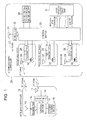
- FIG. 1 is a diagram illustrating a vehicle opening/closing control system according to a first embodiment.
- the vehicle opening/closing control system includes a wireless controller (remote controller) 10 carried by the user and an opening/closing controller 20 carried on the vehicle.
- a wireless controller remote controller
- An example of vehicle door opening/closing control is herein explained based on an instruction from wireless controller 10, wherein the vehicle doors include a sliding door on the driver side, a sliding door on the passenger side and a rear door.
- Wireless controller 10 has a control section 11, an RF transmitter 12, an antenna 13, an LF receiver 14, an antenna 15, and an opening/closing switch 16.
- Opening/closing switch 16 is a switch that causes an instruction signal for opening/closing the vehicle doors to be transmitted.
- control section 11 causes RF transmitter 12 to transmit an opening/closing start request signal and an RF opening/closing execution request signal via antenna 13.
- RF opening/closing start request signal is an instruction signal for starting the vehicle door opening/closing operation
- RF opening/closing execution request signal is a response signal with respect to the LF reception signal, to be explained later.
- the LF receiver 14 receives via antenna 15 the LF reception signal transmitted from opening/closing controller 20.
- the LF reception signal is a signal indicating reception of the RF opening/closing start request signal or the RF opening/closing execution request signal by the opening/closing controller 20, and it is also the signal for checking whether wireless controller 10 is present within prescribed areas 230a-230c, to be explained later.
- control section 11 Based on operation of opening/closing switch 16 by the user, control section 11 sends an instruction to RF transmitter 12 so that the RF opening/closing start request signal is transmitted.
- LF receiver 14 receives the LF reception signal, it also sends an instruction to RF transmitter 12 so that the RF opening/closing execution request signal is transmitted.
- Opening/closing controller 20 has a control section 21, an RF receiver 22, an antenna 23, a first LF transmitter 24, an antenna 25, a second LF transmitter 26, an antenna 27, a third LF transmitter 28, an antenna 29, actuators 30, a door opening/closing drive unit 31 and request switches 32-34.
- RF receiver 22 receives the RF opening/closing start request signal and the RF opening/closing execution request signal transmitted from wireless controller 10.
- First LF transmitter 24 is arranged on the sliding door on the driver side. Based on an instruction from control section 21, first LF transmitter 24 transmits an LF reception signal via antenna 25.
- Second LF transmitter 26 is arranged on the sliding door on the passenger side. Based on an instruction from control section 21, second LF transmitter 26 transmits an LF reception signal via antenna 27.
- Third LF transmitter 28 is arranged on the rear door. Based on an instruction from control section 21, third LF transmitter 28 transmits an LF reception signal via antenna 29.
- an actuator represented generally by actuators 30 Based on an instruction from control section 21, an actuator represented generally by actuators 30 performs a door locking/unlocking operation. Based on an instruction from control section 21, actuators represented generally by actuators 30 drive sliding door opening/closing and rear door opening/dosing, for example, responsive to opening/closing drive unit 31, which is constructed according to known methods.
- the request switches 32-34 are switches operated by the user to perform a door locking/unlocking operation.
- control section 21 sends various instructions to first LF transmitter 24, second LF transmitter 26, third LF transmitter 28 and door opening/closing drive unit 31.
- Wireless controller 10 and opening/closing controller 20 comprise a number of hardware components as described above.
- Control sections 11 and 21 are also called control units herein and generally each comprises a microcomputer including a central processing unit (CPU), input and output ports (I/O), random access memory (RAM), keep alive memory (KAM), a common data bus and read-only memory (ROM) as an electronic storage medium for one or more executable software programs operating as discussed hereinafter.
- CPU central processing unit
- I/O input and output ports
- RAM random access memory
- KAM keep alive memory
- ROM read-only memory
- FIG. 2 is a diagram illustrating the area where the electromagnetic waves of the RF signal and the LF signal can reach.
- An RF signal (RF opening/closing start request signal and RF opening/closing execution request signal) transmitted by wireless controller 10 from area 210 on the outer side of circle 200 cannot reach opening/closing controller 20 mounted on vehicle 1.
- an LF signal (LF reception signal) transmitted by opening/closing controller 20 cannot reach wireless controller 10. Consequently, when an RF signal is transmitted from wireless controller 10 present in area 210, the RF signal cannot reach the opening/closing controller 20.
- Areas 230a, 230b, 230c are areas near antennas 25, 27, 29, respectively. In these areas, the RF signal transmitted from wireless controller 10 can reach vehicle 1, and the LF signal transmitted from opening/closing controller 20 can reach wireless controller 10.
- the door opening/closing operation is continued if the user stays within areas 230a, 230b, 230c.
- the door opening/closing operation is controlled to stop.
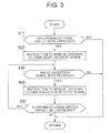
- FIG. 3 is a flow chart illustrating the processing performed by wireless controller 10. Here, the processing performed when the user continues operating opening/closing switch 16 in order to continue the vehicle door opening/closing operation is explained. The processing starting from step S10 is performed by means of control section 11.
- step S10 a judgment is made on whether opening/closing switch 16 has been operated. If it is judged that opening/closing switch 16 has been not operated, the process comes to an end. On the other hand, if it is judged that opening/closing switch 16 has been operated, the process goes to step S20.
- step S20 an instruction is sent to RF transmitter 12 so that it will transmit an RF opening/closing start request signal. After receiving this instruction, RF transmitter 12 transmits the RF opening/closing start request signal via antenna 13.
- step S20 a judgment is made on whether an LF reception signal transmitted from opening/closing controller 20 has been received by LF receiver 14 in step S30. If the LF reception signal has not been received, the flow chart processing comes to an end. If the LF reception signal has been received, the process goes to step S40.
- step S40 an instruction is sent to RF transmitter 12 for an RF opening/closing execution request signal to be transmitted. After receiving this instruction, RF transmitter 12 transmits an RF opening/closing execution request signal via antenna 13.
- step S50 a judgment is made on whether opening/closing switch 16 continues to be operated. If opening/closing switch 16 continues to be operated, process flow returns to step S30. On the other hand, if opening/closing switch 16 is not being operated, the process comes to an end.
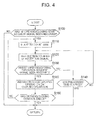
- FIG. 4 is a flow chart illustrating the processing performed by opening/closing controller 20.
- the processing starting from step S100 is performed by control section 21.
- step S100 a judgment is made on whether an RF opening/closing start request signal transmitted from wireless controller 10 has been received by RF receiver 22. If an RF opening/closing start request signal has not been received, the flow chart processing comes to an end. In contrast, if an RF opening/closing start request signal has been received, the process goes to step S110.
- step S110 time counting is started by means of a timer provided inside control section 21, and the process then goes to step S120.
- step S120 an instruction is sent from wireless controller 10 to first LF transmitter 24, second LF transmitter 26 and third LF transmitter 28 such that an LF reception signal indicating reception of the RF opening/closing start request signal is transmitted.
- first LF transmitter 24, second LF transmitter 26 and third LF transmitter 28, respectively transmit the LF reception signals.
- step S120 a judgment is made on whether the RF opening/closing execution request signal transmitted from wireless controller 10 has been received by RF receiver 22 in step S130.
- step S140 When an RF opening/closing execution request signal has not been received, the process goes to step S140.
- step S150 When an RF opening/closing execution request signal has been received, the process goes to step S150.
- step S140 a judgment is made on whether the elapsed time counted by the timer started in step S110 has reached the prescribed time. When the prescribed time has been reached, the flow chart processing comes to an end. If the prescribed time has not been reached, the process returns to step S120.
- step S150 an instruction for performing the opening operation or closing operation of the doors according to the opening/closing instruction is sent to door opening/closing drive unit 31.
- the RF opening/closing start request signal contains data requesting the opening operation or the closing operation and data specifying the door to be opened/closed
- control section 21 instructs door opening/closing drive unit 31 as to which door should be opened/closed based on the received RF opening/closing start request signal.
- door opening/closing drive unit 31 receives a door opening operation instruction, it starts control to open the specified door using the appropriate actuator 30.
- door opening/closing drive unit 31 receives a door closing operation instruction, it starts closing the specified door using the appropriate actuator 30.
- step S150 a judgment is made on whether control for opening the specified door or control for closing the specified door has come to an end (i.e., has been completed) in step S160. If it is judged that door opening/closing control has not come to an end, the process returns to step S110, and when it is judged that opening/closing control has come to an end, the process ends.
- opening/closing controller 20 transmits the LF reception signal.
- wireless controller 10 is present in areas 230a, 230b, 230c shown in FIG. 2, the LF reception signal can be received, and when the LF reception signal is received, the RF opening/closing execution request signal is transmitted.
- opening/closing controller 20 repeatedly transmits the LF reception signal, and the door opening/closing operation is continued during the period when the RF opening/closing execution request signal continues to be received from wireless controller 10. Also, if the RF opening/closing execution request signal from wireless controller 10 cannot be received, the door opening operation or closing operation is stopped.
- the opening/closing operation of the specified door can only continue while the user owning wireless controller 10 is present within the prescribed range of the vehicle.
- the door opening/closing operation can continue.
- the user should continue operating opening/closing switch 16 in areas 230a, 230b, 230c in order to continue the opening/closing control of the door.
- door opening/closing control can still be continued even when the operation of opening/closing switch 16 is not continued as long as the user is within areas 230a, 230b, 230c.
- the processing performed on the side of wireless controller 10 to achieve this is explained with reference to the flow chart shown in FIG. 5.
- step S50 when it is concluded that the LF reception signal transmitted from opening/closing controller 20 has been received by LF receiver 14, in step S40 the RF opening/closing execution request signal is transmitted via antenna 15. Then, even if the user does not continue operating opening/closing switch 16, it is possible to receive the LF reception signal as long as the user is within areas 230a, 230b, 230c, so that the RF opening/closing execution request signal continues to be transmitted based on reception of the LF reception signal. According to this method, once the user operates opening/closing switch 16, there is no need to continue operating opening/closing switch 16. As a result, the process becomes more convenient.
- the RF opening/closing start request signal transmitted from wireless controller 10 is received by opening/closing controller 20
- the opening/closing operation of the opening/closing object (door) of the vehicle is continued.
- the opening/closing instruction for opening/closing the object is sent, if the user carrying wireless controller 10 departs from the vehicle and leaves the prescribed range, the opening/closing operation of the opening/closing object can be stopped.
- opening/closing controller 20 transmits the LF reception signal to check whether wireless controller 10 is present within the prescribed range. If wireless controller 10 returns the response signal (RF opening/closing execution request signal) with respect to the LF reception signal, it is judged that wireless controller 10 is present within the prescribed range of the vehicle. As a result, it is possible to judge reliably whether wireless controller 10 is present within the prescribed range of the vehicle. Also, opening/closing controller 20 transmits the LF reception signal to check whether wireless controller 10 is outside the prescribed range. If wireless controller 10 does not return the response signal (RF opening/closing execution request signal) with respect to the LF reception signal, it is concluded that wireless controller 10 is outside the prescribed range of the vehicle. As a result, it is possible to make a reliable judgment on whether wireless controller 10 is outside the prescribed range of the vehicle.
- a vehicle opening/closing control system is the same as that of the vehicle opening/closing control system except with respect to the content of the processing performed inside wireless controller 10 and opening/closing controller 20.
- the reception level (reception intensity) of the received LF reception signal is compared with a prescribed reception level, and the RF opening/closing execution request signal is transmitted to opening/closing controller 20 when the reception level of the LF reception signal is higher than the prescribed reception level.
- the prescribed reception level is contained as data in the LF reception signal transmitted from opening/closing controller 20.
- the prescribed reception level is preset in control section 21 of opening/closing controller 20 based on the reception sensitivity of wireless controller 10 and the detection range of wireless controller 10. For example, this setup operation can be performed at the manufacturing plant.
- opening/closing controller 20 transmits the preset reception level data in the LF reception signal.
- FIG. 6 is a flow chart illustrating the processing performed in wireless controller 10 in the second embodiment. Like reference numerals are used for like steps as explained with regard to FIG. 3. The processing of steps S10-S30 in FIG. 6 proceeds as previously described with respect to FIG. 3. In FIG. 6, however, when the judgment result in step S30 is YES, process flow goes to step S200.
- step S200 a judgment is made on whether the reception level of the LF reception signal received from opening/closing controller 20 is higher than the prescribed reception level contained as data in the received LF reception signal. If the reception level of the received LF reception signal is higher than the prescribed reception level, the process advances to step S40.
- step S40 an instruction is sent to RF transmitter 12 such that the RF opening/closing execution request signal is transmitted. After receiving this instruction, RF transmitter 12 transmits the RF opening/closing execution request signal via antenna 15.
- step S200 when the response to step S200 is that the reception level of the LF reception signal received from opening/closing controller 20 is lower than the prescribed reception level, the flow chart processing shown in FIG. 6 comes to an end.
- the flow chart shown in FIG. 7 corresponds in part to the flow chart shown in FIG. 5 but differs in that step S200A is added between steps S30 and S40.
- step S200A a judgment is made on whether the reception level of the LF reception signal received from opening/closing controller 20 is higher than a prescribed reception level. If the reception level is higher than the prescribed reception level, the process advances to step S40. On the other hand, if the reception level of the LF reception signal is lower than the prescribed reception level, the flow chart processing shown in FIG. 7 comes to an end.
- a response signal (RF opening/closing execution request signal) is returned.
- RF opening/closing execution request signal RF opening/closing execution request signal
- FIG. 8 is a diagram illustrating the relationship between the range where the LF reception signal can reach and the range where a judgment is made that wireless controller 10 is present within the prescribed range of the vehicle. If wireless controller 10 is within signal-reachable ranges 80a-80c, it is possible to receive the LF reception signal. Among these, when wireless controller 10 is within areas 81a-81c where the reception level of the LF reception signal is higher than the prescribed reception level, a response signal (RF opening/closing execution request signal) is returned. Areas 81 a-81 c can be set at will by changing the prescribed reception level. That is, when the prescribed reception level is raised, areas 81a-81c are reduced, and when the prescribed reception level is lowered, areas 81 a-81 c are expanded.
- a vehicle opening/closing control system In a vehicle opening/closing control system according to a third embodiment, power consumption of the wireless controller 10 is reduced.
- the LF reception signal is transmitted repeatedly from opening/closing controller 20, and the RF opening/closing execution request signal is transmitted as a response from wireless controller 10 repeatedly until the opening/closing control of the door is complete. That is, during the period until the opening/closing control of the door is complete, wireless controller 10 repeatedly transmits the RF opening/closing execution request signal.
- the interval for transmitting the RF opening/closing execution request signal from wireless controller 10 can be extended, and accordingly the electric power consumption of wireless controller 10 is reduced.
- the constitution of the vehicle opening/closing control system according to the third embodiment is otherwise identical to that of the vehicle opening/closing control system according to the first embodiment, and it differs only in the processing performed in wireless controller 10 and opening/closing controller 20.
- FIG. 9 is a diagram illustrating the signal timing for opening/closing controller 20 and wireless controller 10 in the vehicle opening/closing control system according to the first and second embodiments.
- wireless controller 10 receives the LF reception signal from opening/closing controller 20, it transmits the RF opening/closing execution request signal.
- opening/closing controller 20 receives the RF opening/closing execution request signal from wireless controller 10, it transmits the LF reception signal. Accordingly, bidirectional communication between opening/closing controller 20 and wireless controller 10 is maintained.
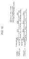
- FIG. 10 is a diagram illustrating the signal timing for opening/closing controller 20 and wireless controller 10 in the vehicle opening/closing control system according to the third embodiment.
- wireless controller 10 receives the LF reception signal from opening/closing controller 20
- opening/closing controller 20 transmits the RF opening/closing execution request signal.
- the LF reception signal is transmitted after a prescribed time T1 has elapsed.
- T1 a prescribed time
- the transmission interval for the RF opening/closing execution request signals transmitted from wireless controller 10 will be longer than the prescribed time T1.
- the interval between reception of the RF opening/closing execution request signal and transmission of the LF reception signal is constant at T1. It is also possible to change this interval, however. For example, assuming this transmission interval immediately after the start of door opening/closing control to be T1, after the door opening/closing operation has progressed a certain amount, the transmission interval can become T2 (shorter than T1).
- FIG. 11 shows the signal timing when the transmission interval immediately after the start of door opening/closing control is T1, and the transmission interval becomes T2 after the door opening/closing operation has progressed a certain amount.
- the door opening/closing operation is stopped by the opening/closing controller 20 if no RF opening/closing execution request signal is transmitted from wireless controller 10 in response to the LF reception signal.
- the door opening/closing control be stopped quickly if the user is out of the area where wireless controller 10 can receive the LF reception signal. Consequently, as shown in FIG.
- the transmission interval between the RF opening/closing execution request signals transmitted from wireless controller 10 is longer than a prescribed time T1, so that it is possible to cut the electric power demand on the battery of wireless controller 10.
- a prescribed time T1 so that it is possible to cut the electric power demand on the battery of wireless controller 10.
- the transmission interval of the response signals (RF opening/closing execution request signals) transmitted by wireless controller 10 can be changed during the opening/closing operation until the operation is complete.
- the signal transmission interval at the end of the opening/closing operation of the opening/closing object is shorter than that at the start, so that the door opening/closing control can be stopped more quickly when the user is away from the vehicle.
- the transmission interval between the LF reception signals transmitted by opening/closing controller 20 can be changed during the opening/closing operation until the operation is complete.
- the signal transmission interval at the end of the opening/closing operation of the opening/closing object is shorter than that at the start.
- the vehicle opening/closing object refers to a sliding door on the driver side, a sliding door on the passenger side and a rear door in the example presented above.
- the opening/closing object is not limited to the vehicle doors, but rather may also include electrically opened and closed windows or an electrically driven roof, such as a sunroof or a convertible top that can be stored in the trunk.
- the sliding door presented as an example of a vehicle door could also be a conventional, hinged vehicle door adapted for electrically-driven opening and closing.
- the LF reception signal is transmitted from first LF transmitter 24, second LF transmitter 26 and third LF transmitter 28.
- a scheme can also be adopted in which the LF reception signal is transmitted only from the LF transmitter provided corresponding to the door to which the opening/closing instruction is sent by the user.
- the LF reception signal is transmitted only from third LF transmitter 28 provided corresponding to the rear door. In this case, the opening operation of the rear door is continued as long as the user is in area 230c shown in FIG. 2.
- the signal transmission interval at the end of the opening/closing operation of the opening/closing object is shorter than that at the start of the opening/closing operation of the opening/closing object (see FIG. 11).
- the interval between reception of the RF opening/closing execution request signal by opening/closing controller 20 and transmission of the LF reception signal that is, the transmission interval for the LF reception signal of opening/closing controller 20 and the transmission interval for the RF opening/closing execution request signal of wireless controller 10
- the transmission interval can be made shorter or it can be made gradually shorter in steps.
- the RF opening/closing start request signal transmitted from wireless controller 10 is received by opening/closing controller 20, a judgment is made on whether wireless controller 10 is present within the prescribed range of the vehicle.
- the opening/closing operation of the opening/closing object (here, a door) of the vehicle can be continued only during the period when it is judged that the wireless controller is within the prescribed range.
- the invention is not limited to this scheme, however. For example, the following scheme can also be adopted.
- opening/closing controller 20 transmits the LF reception signal for checking whether wireless controller 10 is outside the prescribed range, and wireless controller 10 does not return the response signal (RF opening/closing execution request signal) with respect to the LF reception signal, it can be concluded that wireless controller 10 is outside the prescribed range of the vehicle.
- the opening/closing operation of the opening/closing object can be stopped if the user carrying wireless controller 10 is away from the vehicle and outside the prescribed range.
- the opening/closing operation of the opening/closing object is stopped when the user carrying wireless controller 10 is away from the vehicle and outside a prescribed range.
- the opening/closing operation may be reversed to return the opening/closing object to the state that it was in before the RF opening/closing start request signal was received (such as the fully closed state).
Landscapes
- Engineering & Computer Science (AREA)
- Mechanical Engineering (AREA)
- Computer Networks & Wireless Communication (AREA)
- Physics & Mathematics (AREA)
- General Physics & Mathematics (AREA)
- Lock And Its Accessories (AREA)
- Power-Operated Mechanisms For Wings (AREA)
Abstract
Description
- The invention relates generally to a control system and control method for performing an opening/closing operation of a vehicle while a wireless controller is within a prescribed range of the vehicle. Aspects of the invention relate to a system, to a method and to a vehicle.
- There are known devices for preventing doors from opening/closing due to malfunctions. For example, in
Japanese Kokai Patent Application No. 2005-1573 - It is an aim of the invention to improve upon such devices. Other aims and advantages of the invention will become apparent from the following description, claims and drawings.
- Aspects of the invention therefore provide a system, a method and a vehicle as claimed in the appended claims.
- According to another aspect of the invention there is provided an opening and closing control system for a vehicle, comprising a receiver configured to receive an opening or closing instruction signal from a wireless controller and a control unit configured to receive the instruction signal from the receiver, the control unit operable to judge whether the wireless controller is present within a prescribed range of the vehicle and perform an open or close operation of the vehicle when the receiver receives the instruction signal and while the wireless controller is present within the prescribed range.
- In an embodiment, the controller is further operable to signal the drive unit to stop the open or close operation if the wireless controller leaves the prescribed range during the open or close operation.
- The system may comprise a transmitter electrically coupled to the control unit and configured to transmit a prescribed signal; and wherein the control unit is further operable to judge that the wireless controller is absent from the prescribed range of the vehicle when no response signal is received from the wireless controller responsive to the prescribed signal.
- The system may comprise a transmitter electrically coupled to the control unit and configured to transmit a prescribed signal; and wherein the control unit is further operable to judge whether the wireless controller is present within the prescribed range of the vehicle when the wireless controller returns a response signal responsive to the prescribed signal.
- In an embodiment, the transmitter is further configured to transmit the prescribed signal repeatedly at a transmission interval of at least a prescribed period of time.
- In an embodiment, the transmitter is further configured to change the transmission interval of the prescribed signal during the open or close operation.
- In an embodiment, a second transmission interval at an end of the open or close operation is shorter than a first transmission interval at a start of the open or close operation.
- In an embodiment, the control unit is further configured to change an interval of the response signal of the wireless controller by controlling the transmitter to transmit the prescribed signal at an interval longer than a prescribed time until the open or close operation of the vehicle component is complete.
- In an embodiment, the control unit is further configured to change the interval of the response signal by shortening the interval of the response signal at an end of the open or close operation with respect to that at a start of the open or close operation.
- In an embodiment, the wireless controller is configured to return the response signal responsive to the prescribed signal when a reception level of the prescribed signal is higher than a prescribed reception level.
- The prescribed reception level may be contained in the prescribed signal. Alternatively, or in addition, the prescribed reception level may be stored in the wireless controller.
- In an embodiment, the vehicle component is at least one of a window, a door and an electrically-driven roof.
- According to another aspect of the invention there is provided an opening and closing control system for a vehicle, comprising means for receiving an opening or closing instruction signal for a vehicle component from a wireless controller, means for judging whether the wireless controller is present within a prescribed range of the vehicle and means for performing an open or close operation of the vehicle component when the receiving means receives the instruction signal and while the wireless controller is present within the prescribed range.
- According to a further aspect of the invention there is provided an opening and closing control system for a vehicle, comprising a receiver configured to receive an opening or closing instruction signal from a wireless controller and a control unit configured to receive the instruction signal from the receiver to start and open or close operation, the control unit operable to judge whether the wireless controller is outside a prescribed range of the vehicle and stop the open or close operation of the vehicle while the wireless controller is outside the prescribed range during the open or close operation.
- According to a still further aspect of the invention there is provided an opening and closing control method for a vehicle, comprising commencing an open or close operation of a vehicle component in response to an instruction signal for starting the open or close operation and ending the open or close operation if a wireless controller leaves a prescribed range of the vehicle prior to completion of the open or close operation.
- The method may comprise transmitting the instruction signal for starting the open or close operation using the wireless controller.
- The method may comprise periodically transmitting a prescribed signal to the wireless controller from the vehicle after commencing the open or close operation and judging if the wireless controller leaves the prescribed range of the vehicle prior to completion of the open or close operation when the wireless controller does not transmit a reception signal responsive to the prescribed signal.
- The method may comprise changing a period of transmission of the prescribed signal while performing the open or close operation.
- In an embodiment the method comprises transmitting the reception signal from the wireless controller when a reception level of the prescribed signal by the wireless controller is higher than a prescribed reception level.
- Within the scope of this application it is envisaged that the various aspects, embodiments, examples, features and alternatives set out in the preceding paragraphs, in the claims and/or in the following description may be taken individually or in any combination thereof.
- The present invention will now be described, by way of example only, with reference to the accompanying drawings in which:
- FIG. 1 is a diagram illustrating a vehicle opening/closing control system according to a first embodiment;
- FIG. 2 is a diagram illustrating the coverage areas of an RF signal and an LF signal;
- FIG. 3 is a flow chart illustrating the processing performed by a wireless controller according to an example;
- FIG. 4 is a flow chart illustrating the processing performed by an opening/closing controller according to an example;
- FIG. 5 is a flow chart illustrating the processing performed by a wireless controller according to an example where the system according to the first embodiment does not require continued operation of the opening/closing switch;
- FIG. 6 is a flow chart illustrating the processing performed by the wireless controller in a vehicle opening/closing control system according to a second embodiment;
- FIG. 7 is a flow chart illustrating processing performed by the wireless controller in an example wherein the system according to the embodiment does not require continued operation of the opening/closing switch;
- FIG. 8 is a diagram illustrating an example of the relationship between the signal range of an LF reception signal and a prescribed range of the vehicle;
- FIG. 9 is a diagram illustrating the signal timing for the opening/closing controller and wireless controller in the vehicle opening/closing control system in the first and second embodiments;
- FIG. 10 is a diagram illustrating the signal timing for the opening/closing controller and wireless controller in a vehicle opening/closing control system according to a third embodiment; and
- FIG. 11 is a diagram illustrating the signal timing wherein the initial transmission interval of the door opening/closing operation is initially set at T1 and subsequently set at T2.
- FIG. 1 is a diagram illustrating a vehicle opening/closing control system according to a first embodiment. The vehicle opening/closing control system includes a wireless controller (remote controller) 10 carried by the user and an opening/
closing controller 20 carried on the vehicle. An example of vehicle door opening/closing control is herein explained based on an instruction fromwireless controller 10, wherein the vehicle doors include a sliding door on the driver side, a sliding door on the passenger side and a rear door. -
Wireless controller 10 has acontrol section 11, anRF transmitter 12, anantenna 13, anLF receiver 14, anantenna 15, and an opening/closing switch 16. Opening/closing switch 16 is a switch that causes an instruction signal for opening/closing the vehicle doors to be transmitted. Upon operation of opening/closing switch 16,control section 11 causesRF transmitter 12 to transmit an opening/closing start request signal and an RF opening/closing execution request signal viaantenna 13. RF opening/closing start request signal is an instruction signal for starting the vehicle door opening/closing operation, and RF opening/closing execution request signal is a response signal with respect to the LF reception signal, to be explained later. -
LF receiver 14 receives viaantenna 15 the LF reception signal transmitted from opening/closing controller 20. The LF reception signal is a signal indicating reception of the RF opening/closing start request signal or the RF opening/closing execution request signal by the opening/closing controller 20, and it is also the signal for checking whetherwireless controller 10 is present within prescribedareas 230a-230c, to be explained later. - Based on operation of opening/
closing switch 16 by the user,control section 11 sends an instruction toRF transmitter 12 so that the RF opening/closing start request signal is transmitted. WhenLF receiver 14 receives the LF reception signal, it also sends an instruction toRF transmitter 12 so that the RF opening/closing execution request signal is transmitted. - Opening/
closing controller 20 has acontrol section 21, anRF receiver 22, anantenna 23, afirst LF transmitter 24, anantenna 25, asecond LF transmitter 26, anantenna 27, athird LF transmitter 28, anantenna 29,actuators 30, a door opening/closing drive unit 31 and request switches 32-34. - Via
antenna 23,RF receiver 22 receives the RF opening/closing start request signal and the RF opening/closing execution request signal transmitted fromwireless controller 10.First LF transmitter 24 is arranged on the sliding door on the driver side. Based on an instruction fromcontrol section 21,first LF transmitter 24 transmits an LF reception signal viaantenna 25.Second LF transmitter 26 is arranged on the sliding door on the passenger side. Based on an instruction fromcontrol section 21,second LF transmitter 26 transmits an LF reception signal viaantenna 27.Third LF transmitter 28 is arranged on the rear door. Based on an instruction fromcontrol section 21,third LF transmitter 28 transmits an LF reception signal viaantenna 29. - Based on an instruction from
control section 21, an actuator represented generally byactuators 30 performs a door locking/unlocking operation. Based on an instruction fromcontrol section 21, actuators represented generally byactuators 30 drive sliding door opening/closing and rear door opening/dosing, for example, responsive to opening/closing drive unit 31, which is constructed according to known methods. The request switches 32-34 are switches operated by the user to perform a door locking/unlocking operation. As will be explained later,control section 21 sends various instructions tofirst LF transmitter 24,second LF transmitter 26,third LF transmitter 28 and door opening/closing drive unit 31. -
Wireless controller 10 and opening/closing controller 20 comprise a number of hardware components as described above.Control sections - FIG. 2 is a diagram illustrating the area where the electromagnetic waves of the RF signal and the LF signal can reach. An RF signal (RF opening/closing start request signal and RF opening/closing execution request signal) transmitted by
wireless controller 10 fromarea 210 on the outer side ofcircle 200 cannot reach opening/closing controller 20 mounted onvehicle 1. Also, an LF signal (LF reception signal) transmitted by opening/closing controller 20 cannot reachwireless controller 10. Consequently, when an RF signal is transmitted fromwireless controller 10 present inarea 210, the RF signal cannot reach the opening/closing controller 20. - Among the areas on the inner side of
circle 200, although the RF signal transmitted fromwireless controller 10 fromarea 220 excludingareas 230a-230c can reach opening/closing controller 20 mounted onvehicle 1, the LF signal transmitted from opening/closing controller 20 cannot reachwireless controller 10.Areas antennas wireless controller 10 can reachvehicle 1, and the LF signal transmitted from opening/closing controller 20 can reachwireless controller 10. - In the vehicle opening/closing control system according to the first embodiment, after the user operates opening/
closing switch 16 to send a vehicle door opening/closing instruction, the door opening/closing operation is continued if the user stays withinareas areas closing switch 16 the door opening/closing operation is controlled to stop. - FIG. 3 is a flow chart illustrating the processing performed by
wireless controller 10. Here, the processing performed when the user continues operating opening/closing switch 16 in order to continue the vehicle door opening/closing operation is explained. The processing starting from step S10 is performed by means ofcontrol section 11. - In step S10, a judgment is made on whether opening/
closing switch 16 has been operated. If it is judged that opening/closing switch 16 has been not operated, the process comes to an end. On the other hand, if it is judged that opening/closing switch 16 has been operated, the process goes to step S20. In step S20, an instruction is sent toRF transmitter 12 so that it will transmit an RF opening/closing start request signal. After receiving this instruction,RF transmitter 12 transmits the RF opening/closing start request signal viaantenna 13. - After step S20, a judgment is made on whether an LF reception signal transmitted from opening/
closing controller 20 has been received byLF receiver 14 in step S30. If the LF reception signal has not been received, the flow chart processing comes to an end. If the LF reception signal has been received, the process goes to step S40. - In step S40 an instruction is sent to
RF transmitter 12 for an RF opening/closing execution request signal to be transmitted. After receiving this instruction,RF transmitter 12 transmits an RF opening/closing execution request signal viaantenna 13. In next step S50, a judgment is made on whether opening/closing switch 16 continues to be operated. If opening/closing switch 16 continues to be operated, process flow returns to step S30. On the other hand, if opening/closing switch 16 is not being operated, the process comes to an end. - FIG. 4 is a flow chart illustrating the processing performed by opening/
closing controller 20. The processing starting from step S100 is performed bycontrol section 21. In step S100, a judgment is made on whether an RF opening/closing start request signal transmitted fromwireless controller 10 has been received byRF receiver 22. If an RF opening/closing start request signal has not been received, the flow chart processing comes to an end. In contrast, if an RF opening/closing start request signal has been received, the process goes to step S110. - In step S110 time counting is started by means of a timer provided inside
control section 21, and the process then goes to step S120. In step S120 an instruction is sent fromwireless controller 10 tofirst LF transmitter 24,second LF transmitter 26 andthird LF transmitter 28 such that an LF reception signal indicating reception of the RF opening/closing start request signal is transmitted. After receiving this instruction,first LF transmitter 24,second LF transmitter 26 andthird LF transmitter 28, respectively, transmit the LF reception signals. - After step S120 a judgment is made on whether the RF opening/closing execution request signal transmitted from
wireless controller 10 has been received byRF receiver 22 in step S130. When an RF opening/closing execution request signal has not been received, the process goes to step S140. When an RF opening/closing execution request signal has been received, the process goes to step S150. - In step S140 a judgment is made on whether the elapsed time counted by the timer started in step S110 has reached the prescribed time. When the prescribed time has been reached, the flow chart processing comes to an end. If the prescribed time has not been reached, the process returns to step S120.
- On the other hand, in step S150 an instruction for performing the opening operation or closing operation of the doors according to the opening/closing instruction is sent to door opening/
closing drive unit 31. Because the RF opening/closing start request signal contains data requesting the opening operation or the closing operation and data specifying the door to be opened/closed,control section 21 instructs door opening/closing drive unit 31 as to which door should be opened/closed based on the received RF opening/closing start request signal. When door opening/closing drive unit 31 receives a door opening operation instruction, it starts control to open the specified door using theappropriate actuator 30. In contrast, when door opening/closing drive unit 31 receives a door closing operation instruction, it starts closing the specified door using theappropriate actuator 30. - After step S150 a judgment is made on whether control for opening the specified door or control for closing the specified door has come to an end (i.e., has been completed) in step S160. If it is judged that door opening/closing control has not come to an end, the process returns to step S110, and when it is judged that opening/closing control has come to an end, the process ends.
- The operation of the vehicle opening/closing control system according to the first embodiment can be summarized. When the RF opening/closing start request signal from
wireless controller 10 is received by opening/closing controller 20, opening/closingcontroller 20 transmits the LF reception signal. Whenwireless controller 10 is present inareas controller 20 repeatedly transmits the LF reception signal, and the door opening/closing operation is continued during the period when the RF opening/closing execution request signal continues to be received fromwireless controller 10. Also, if the RF opening/closing execution request signal fromwireless controller 10 cannot be received, the door opening operation or closing operation is stopped. - That is, the opening/closing operation of the specified door can only continue while the user owning
wireless controller 10 is present within the prescribed range of the vehicle. As a result, only when the user is in a position where the door opening/closing operation can be checked can the door opening/closing operation continue. - Also, in this control, the user should continue operating opening/
closing switch 16 inareas closing switch 16 once, door opening/closing control can still be continued even when the operation of opening/closing switch 16 is not continued as long as the user is withinareas wireless controller 10 to achieve this is explained with reference to the flow chart shown in FIG. 5. - In the flow chart shown in FIG. 5, the like reference numerals refer to identical steps as explained in regard to FIG. 3. However, the process shown in FIG. 5 differs from the process shown in FIG. 3 in that it omits step S50. That is, in step S30, when it is concluded that the LF reception signal transmitted from opening/
closing controller 20 has been received byLF receiver 14, in step S40 the RF opening/closing execution request signal is transmitted viaantenna 15. Then, even if the user does not continue operating opening/closing switch 16, it is possible to receive the LF reception signal as long as the user is withinareas closing switch 16, there is no need to continue operating opening/closing switch 16. As a result, the process becomes more convenient. - For the vehicle opening/closing control system according to the first embodiment, when the RF opening/closing start request signal transmitted from
wireless controller 10 is received by opening/closing controller 20, a judgment is made on whetherwireless controller 10 is present within the prescribed range of the vehicle. As long aswireless controller 10 is present in the prescribed range, the opening/closing operation of the opening/closing object (door) of the vehicle is continued. As a result, after the opening/closing instruction for opening/closing the object is sent, if the user carryingwireless controller 10 departs from the vehicle and leaves the prescribed range, the opening/closing operation of the opening/closing object can be stopped. - Also, in the vehicle opening/closing control system according to the first embodiment, opening/closing
controller 20 transmits the LF reception signal to check whetherwireless controller 10 is present within the prescribed range. Ifwireless controller 10 returns the response signal (RF opening/closing execution request signal) with respect to the LF reception signal, it is judged thatwireless controller 10 is present within the prescribed range of the vehicle. As a result, it is possible to judge reliably whetherwireless controller 10 is present within the prescribed range of the vehicle. Also, opening/closingcontroller 20 transmits the LF reception signal to check whetherwireless controller 10 is outside the prescribed range. Ifwireless controller 10 does not return the response signal (RF opening/closing execution request signal) with respect to the LF reception signal, it is concluded thatwireless controller 10 is outside the prescribed range of the vehicle. As a result, it is possible to make a reliable judgment on whetherwireless controller 10 is outside the prescribed range of the vehicle. - A vehicle opening/closing control system according to a second embodiment is the same as that of the vehicle opening/closing control system except with respect to the content of the processing performed inside
wireless controller 10 and opening/closing controller 20. - In the vehicle opening/closing control system according to the second embodiment, when
wireless controller 10 receives the LF reception signal, the reception level (reception intensity) of the received LF reception signal is compared with a prescribed reception level, and the RF opening/closing execution request signal is transmitted to opening/closing controller 20 when the reception level of the LF reception signal is higher than the prescribed reception level. The prescribed reception level is contained as data in the LF reception signal transmitted from opening/closing controller 20. - The prescribed reception level is preset in
control section 21 of opening/closing controller 20 based on the reception sensitivity ofwireless controller 10 and the detection range ofwireless controller 10. For example, this setup operation can be performed at the manufacturing plant. When the LF reception signal is transmitted, opening/closingcontroller 20 transmits the preset reception level data in the LF reception signal. - FIG. 6 is a flow chart illustrating the processing performed in
wireless controller 10 in the second embodiment. Like reference numerals are used for like steps as explained with regard to FIG. 3. The processing of steps S10-S30 in FIG. 6 proceeds as previously described with respect to FIG. 3. In FIG. 6, however, when the judgment result in step S30 is YES, process flow goes to step S200. - In step S200 a judgment is made on whether the reception level of the LF reception signal received from opening/
closing controller 20 is higher than the prescribed reception level contained as data in the received LF reception signal. If the reception level of the received LF reception signal is higher than the prescribed reception level, the process advances to step S40. In step S40, an instruction is sent toRF transmitter 12 such that the RF opening/closing execution request signal is transmitted. After receiving this instruction,RF transmitter 12 transmits the RF opening/closing execution request signal viaantenna 15. - On the other hand, when the response to step S200 is that the reception level of the LF reception signal received from opening/
closing controller 20 is lower than the prescribed reception level, the flow chart processing shown in FIG. 6 comes to an end. - Also, in the flow chart shown in FIG. 6 the processing is explained for a situation where it is necessary to continue operating opening/
closing switch 16 to continue the door opening/closing control. However, even when the user simply operates opening/closing switch 16 once, the same processing can be performed to continue the door opening/closing operation. The processing performed on the side ofwireless controller 10 can be explained with reference to the flow chart shown in FIG. 7. - The flow chart shown in FIG. 7 corresponds in part to the flow chart shown in FIG. 5 but differs in that step S200A is added between steps S30 and S40. In step S200A, a judgment is made on whether the reception level of the LF reception signal received from opening/
closing controller 20 is higher than a prescribed reception level. If the reception level is higher than the prescribed reception level, the process advances to step S40. On the other hand, if the reception level of the LF reception signal is lower than the prescribed reception level, the flow chart processing shown in FIG. 7 comes to an end. - According to the vehicle opening/closing control system of the second embodiment, if the reception level when the LF reception signal is received by
wireless controller 10 is higher than the prescribed reception level, a response signal (RF opening/closing execution request signal) is returned. As a result, it is possible to set the range where it is judged thatwireless controller 10 is present within the prescribed range of the vehicle inside the range reached by the LF reception signal. - FIG. 8 is a diagram illustrating the relationship between the range where the LF reception signal can reach and the range where a judgment is made that
wireless controller 10 is present within the prescribed range of the vehicle. Ifwireless controller 10 is within signal-reachable ranges 80a-80c, it is possible to receive the LF reception signal. Among these, whenwireless controller 10 is withinareas 81a-81c where the reception level of the LF reception signal is higher than the prescribed reception level, a response signal (RF opening/closing execution request signal) is returned. Areas 81 a-81 c can be set at will by changing the prescribed reception level. That is, when the prescribed reception level is raised,areas 81a-81c are reduced, and when the prescribed reception level is lowered, areas 81 a-81 c are expanded. - Also, even when there is variation in the reception sensitivity of
wireless controller 10, by setting the prescribed reception level corresponding to the variation in the reception sensitivity ofwireless controller 10, it is possible to ensure consistent ranges where it is judged thatwireless controller 10 is present. - In a vehicle opening/closing control system according to a third embodiment, power consumption of the
wireless controller 10 is reduced. In the first and second embodiments, as the user operates opening/closing switch 16, the LF reception signal is transmitted repeatedly from opening/closing controller 20, and the RF opening/closing execution request signal is transmitted as a response fromwireless controller 10 repeatedly until the opening/closing control of the door is complete. That is, during the period until the opening/closing control of the door is complete,wireless controller 10 repeatedly transmits the RF opening/closing execution request signal. As a result, the electric power demand on the battery rises. In the vehicle opening/closing control system according to the third embodiment, the interval for transmitting the RF opening/closing execution request signal fromwireless controller 10 can be extended, and accordingly the electric power consumption ofwireless controller 10 is reduced. - The constitution of the vehicle opening/closing control system according to the third embodiment is otherwise identical to that of the vehicle opening/closing control system according to the first embodiment, and it differs only in the processing performed in
wireless controller 10 and opening/closing controller 20. - FIG. 9 is a diagram illustrating the signal timing for opening/
closing controller 20 andwireless controller 10 in the vehicle opening/closing control system according to the first and second embodiments. As explained above, whenwireless controller 10 receives the LF reception signal from opening/closing controller 20, it transmits the RF opening/closing execution request signal. When opening/closing controller 20 receives the RF opening/closing execution request signal fromwireless controller 10, it transmits the LF reception signal. Accordingly, bidirectional communication between opening/closing controller 20 andwireless controller 10 is maintained. - FIG. 10 is a diagram illustrating the signal timing for opening/
closing controller 20 andwireless controller 10 in the vehicle opening/closing control system according to the third embodiment. Whenwireless controller 10 receives the LF reception signal from opening/closing controller 20, opening/closingcontroller 20 transmits the RF opening/closing execution request signal. When opening/closing controller 20 receives the RF opening/closing execution request signal fromwireless controller 10, the LF reception signal is transmitted after a prescribed time T1 has elapsed. As a result, compared with the case when the LF reception signal is transmitted soon after reception of the RF opening/closing execution request signal (see FIG. 9), the number of repetitions of transmission of the LF reception signal can be reduced. Consequently, the number of repetitions of transmission of the RF opening/closing execution request signal transmitted fromwireless controller 10 is also reduced. As a result, it is possible to cut the electric power demand on the battery inwireless controller 10. In this case, the transmission interval for the RF opening/closing execution request signals transmitted fromwireless controller 10 will be longer than the prescribed time T1. - With the signal timing shown in FIG. 10, the interval between reception of the RF opening/closing execution request signal and transmission of the LF reception signal is constant at T1. It is also possible to change this interval, however. For example, assuming this transmission interval immediately after the start of door opening/closing control to be T1, after the door opening/closing operation has progressed a certain amount, the transmission interval can become T2 (shorter than T1). FIG. 11 shows the signal timing when the transmission interval immediately after the start of door opening/closing control is T1, and the transmission interval becomes T2 after the door opening/closing operation has progressed a certain amount.
- As explained above, the door opening/closing operation is stopped by the opening/
closing controller 20 if no RF opening/closing execution request signal is transmitted fromwireless controller 10 in response to the LF reception signal. Here, when the door is being closed, it is preferable that the door opening/closing control be stopped quickly if the user is out of the area wherewireless controller 10 can receive the LF reception signal. Consequently, as shown in FIG. 11, when the door opening/closing operation has progressed a certain amount, it is possible to check whetherwireless controller 10 is present within the range where the wireless controller can receive the LF reception signal more quickly by shortening the interval between reception of the RF opening/closing execution request signal to transmission of the LF reception signal, so that when the user is away from the vehicle, the door opening/closing control can be stopped more quickly. - In the vehicle opening/closing control system according to the third embodiment, the transmission interval between the RF opening/closing execution request signals transmitted from
wireless controller 10 is longer than a prescribed time T1, so that it is possible to cut the electric power demand on the battery ofwireless controller 10. In particular, by making the transmission interval between the LF reception signals transmitted from opening/closing controller 20 longer than the prescribed time T1, it is possible to make the transmission interval between the response signals (RF opening/closing execution request signals) ofwireless controller 10 to the LF reception signals longer than the prescribed time T1. - Also, according to the vehicle opening/closing control system of the third embodiment, the transmission interval of the response signals (RF opening/closing execution request signals) transmitted by
wireless controller 10 can be changed during the opening/closing operation until the operation is complete. In particular, the signal transmission interval at the end of the opening/closing operation of the opening/closing object is shorter than that at the start, so that the door opening/closing control can be stopped more quickly when the user is away from the vehicle. - Further, according to the vehicle opening/closing control system of the third embodiment, the transmission interval between the LF reception signals transmitted by opening/
closing controller 20 can be changed during the opening/closing operation until the operation is complete. In particular, the signal transmission interval at the end of the opening/closing operation of the opening/closing object is shorter than that at the start. As a result, it is possible for the door opening/closing control to be stopped more quickly when the user is away from the vehicle. - The invention is not limited to these described embodiments. For example, the vehicle opening/closing object refers to a sliding door on the driver side, a sliding door on the passenger side and a rear door in the example presented above. However, the opening/closing object is not limited to the vehicle doors, but rather may also include electrically opened and closed windows or an electrically driven roof, such as a sunroof or a convertible top that can be stored in the trunk. Additionally, the sliding door presented as an example of a vehicle door could also be a conventional, hinged vehicle door adapted for electrically-driven opening and closing.
- In the examples, when opening/
closing controller 20 receives the RF opening/closing start request signal or the RF opening/closing execution request signal fromwireless controller 10, the LF reception signal is transmitted fromfirst LF transmitter 24,second LF transmitter 26 andthird LF transmitter 28. However, a scheme can also be adopted in which the LF reception signal is transmitted only from the LF transmitter provided corresponding to the door to which the opening/closing instruction is sent by the user. For example, when the user sends an instruction to open the rear door by means ofwireless controller 10, the LF reception signal is transmitted only fromthird LF transmitter 28 provided corresponding to the rear door. In this case, the opening operation of the rear door is continued as long as the user is inarea 230c shown in FIG. 2. - For the vehicle opening/closing control system in the second embodiment, a case has been explained in which the data concerning the prescribed reception level for comparison with the reception level of the LF reception signal are contained in the LF reception signal transmitted from opening/
closing controller 20. However, a scheme can also be adopted in which said data is pre-stored incontrol section 11 ofwireless controller 10. - In the vehicle opening/closing control system according to the third embodiment, the signal transmission interval at the end of the opening/closing operation of the opening/closing object is shorter than that at the start of the opening/closing operation of the opening/closing object (see FIG. 11). Here, the interval between reception of the RF opening/closing execution request signal by opening/
closing controller 20 and transmission of the LF reception signal, that is, the transmission interval for the LF reception signal of opening/closing controller 20 and the transmission interval for the RF opening/closing execution request signal ofwireless controller 10, can be divided into three or more steps instead of the described two steps. Accordingly, the transmission interval can be made shorter or it can be made gradually shorter in steps. - In the application examples, when the RF opening/closing start request signal transmitted from
wireless controller 10 is received by opening/closing controller 20, a judgment is made on whetherwireless controller 10 is present within the prescribed range of the vehicle. The opening/closing operation of the opening/closing object (here, a door) of the vehicle can be continued only during the period when it is judged that the wireless controller is within the prescribed range. The invention is not limited to this scheme, however. For example, the following scheme can also be adopted. When opening/closing controller 20 transmits the LF reception signal for checking whetherwireless controller 10 is outside the prescribed range, andwireless controller 10 does not return the response signal (RF opening/closing execution request signal) with respect to the LF reception signal, it can be concluded thatwireless controller 10 is outside the prescribed range of the vehicle. As a result, after the opening/closing instruction for the opening/closing object is transmitted, the opening/closing operation of the opening/closing object can be stopped if the user carryingwireless controller 10 is away from the vehicle and outside the prescribed range. - As described, the opening/closing operation of the opening/closing object is stopped when the user carrying
wireless controller 10 is away from the vehicle and outside a prescribed range. However, instead of maintaining the OFF state even afterwireless controller 10 departs from the prescribed range, the opening/closing operation may be reversed to return the opening/closing object to the state that it was in before the RF opening/closing start request signal was received (such as the fully closed state). - Accordingly, the above-described embodiments have been described in order to allow easy understanding of the invention and do not limit the invention. On the contrary, the invention is intended to cover various modifications and equivalent arrangements included within the scope of the appended claims, which scope is to be accorded the broadest interpretation so as to encompass all such modifications and equivalent structure as is permitted under the law.
- This application claims priority from
Japanese Patent Application No. 2006-219746, filed 11th August 2006
Claims (12)
- An opening and closing control system for a vehicle, comprising:receiver means for receiving an opening or closing instruction signal from a wireless controller; andcontrol means for receiving the instruction signal from the receiver;wherein the control means is arranged to judge whether the wireless controller is within or outside a prescribed range of the vehicle and to:perform an open or close operation of the vehicle when the receiver receives the instruction signal while the wireless controller is present within the prescribed range; and/orstop the open or close operation of the vehicle while the wireless controller is outside the prescribed range during the open or close operation.
- A system as claimed in claim 1 wherein the control means is arranged to signal the drive unit to stop the open or close operation if the wireless controller leaves the prescribed range during the open or close operation.
- A system as claimed in claim 1 or claim 2 comprising transmitter means electrically coupled to the control means and arranged to transmit a prescribed signal;
wherein the control unit is arranged to:judge that the wireless controller is outside the prescribed range of the vehicle when no response signal is received from the wireless controller responsive to the prescribed signal; and/orjudge that the wireless controller is within the prescribed range of the vehicle when the wireless controller returns a response signal responsive to the prescribed signal. - A system as claimed in claim 3 wherein the transmitter means is arranged to transmit the prescribed signal repeatedly at a transmission interval of at least a prescribed period of time.
- A system as claimed in claim 4 wherein the transmitter means is arranged to change the transmission interval of the prescribed signal during the open or close operation.
- A system as claimed in any of claims 3 to 5 wherein the control means is arranged to change an interval of the response signal of the wireless controller:by controlling the transmitter means to transmit the prescribed signal at an interval longer than a prescribed time until the open or close operation of the vehicle component is complete; and/orby shortening the interval of the response signal at an end of the open or close operation with respect to that at a start of the open or close operation.
- A system as claimed in any of claims 3 to 6 wherein the wireless controller is arranged to return the response signal responsive to the prescribed signal when a reception level of the prescribed signal is higher than a prescribed reception level.
- A method for a vehicle comprising:commencing an open or close operation of a vehicle component in response to an instruction signal for starting the open or close operation; andending the open or close operation if a wireless controller leaves a prescribed range of the vehicle prior to completion of the open or close operation.
- A method as claimed in claim 8 comprising:periodically transmitting a prescribed signal to the wireless controller from the vehicle after commencing the open or close operation; andjudging if the wireless controller leaves the prescribed range of the vehicle prior to completion of the open or close operation when the wireless controller does not transmit a reception signal responsive to the prescribed signal.
- A method as claimed in claim 9 comprising changing a period of transmission of the prescribed signal while performing the open or close operation.
- A method as claimed in claim 9 or claim 10 comprising transmitting the reception signal from the wireless controller when a reception level of the prescribed signal by the wireless controller is higher than a prescribed reception level.
- A vehicle having a system as claimed in any of claims 1 to 7.
Applications Claiming Priority (1)
| Application Number | Priority Date | Filing Date | Title |
|---|---|---|---|
| JP2006219746A JP2008045301A (en) | 2006-08-11 | 2006-08-11 | Vehicle open / close control system and vehicle open / close control method |
Publications (1)
| Publication Number | Publication Date |
|---|---|
| EP1887530A1 true EP1887530A1 (en) | 2008-02-13 |
Family
ID=38521495
Family Applications (1)
| Application Number | Title | Priority Date | Filing Date |
|---|---|---|---|
| EP20070113759 Withdrawn EP1887530A1 (en) | 2006-08-11 | 2007-08-03 | Vehicle opening/closing control system and method |
Country Status (4)
| Country | Link |
|---|---|
| US (1) | US20080036571A1 (en) |
| EP (1) | EP1887530A1 (en) |
| JP (1) | JP2008045301A (en) |
| CN (1) | CN101123033A (en) |
Cited By (2)
| Publication number | Priority date | Publication date | Assignee | Title |
|---|---|---|---|---|
| FR2965086A1 (en) * | 2010-09-21 | 2012-03-23 | Continental Automotive France | METHOD OF UNIFORMIZING THE WIDTH OF THE DETECTION AREA, AROUND A VEHICLE, OF A PORTABLE REMOTE CONTROL BOX OF A HANDS-FREE ACCESS SYSTEM TO THE SAME VEHICLE |
| ITRE20150030A1 (en) * | 2015-04-16 | 2016-10-16 | Ferrari Fabrizio | VEHICLE WITH SIDE ACCESS SYSTEM WITH HIDDEN SLIDING DOOR |
Families Citing this family (8)
| Publication number | Priority date | Publication date | Assignee | Title |
|---|---|---|---|---|
| KR100957297B1 (en) * | 2008-04-28 | 2010-05-12 | 현대자동차주식회사 | Smart key detection system |
| CN102381158A (en) * | 2011-09-23 | 2012-03-21 | 奇瑞汽车股份有限公司 | Method and device for ventilation control |
| CN102501826A (en) * | 2011-11-16 | 2012-06-20 | 奇瑞汽车股份有限公司 | Control method and control device for automobiles |
| US9797181B2 (en) * | 2015-08-26 | 2017-10-24 | Tesla, Inc. | Vehicle front door power opening system |
| JP2017096000A (en) * | 2015-11-25 | 2017-06-01 | 株式会社デンソー | Vehicle door control system, on-vehicle device and portable machine |
| US10380817B2 (en) | 2016-11-28 | 2019-08-13 | Honda Motor Co., Ltd. | System and method for providing hands free operation of at least one vehicle door |
| US10815717B2 (en) | 2016-11-28 | 2020-10-27 | Honda Motor Co., Ltd. | System and method for providing hands free operation of at least one vehicle door |
| JP6762904B2 (en) * | 2017-05-09 | 2020-09-30 | 日本電産モビリティ株式会社 | Door control system |
Citations (7)
| Publication number | Priority date | Publication date | Assignee | Title |
|---|---|---|---|---|
| DE19900415A1 (en) * | 1999-01-08 | 2000-07-13 | Kostal Leopold Gmbh & Co Kg | Keyless access control method for motor vehicles involves conducting plausibility check on action signal from ID transmitter to determine whether transmitter is in plausible position for action |
| DE19926234A1 (en) * | 1999-06-10 | 2000-12-14 | Kostal Leopold Gmbh & Co Kg | Method of conducting keyless access authorization checks, e.g. for motor vehicles, involves evaluating difference between reference code signal and response signal characteristic |
| DE19927319A1 (en) * | 1999-06-15 | 2000-12-21 | Mannesmann Vdo Ag | Method for determining the distance between two devices of an identification system |
| DE19941351A1 (en) * | 1999-08-31 | 2001-03-01 | Mannesmann Vdo Ag | Position detection for radio keys |
| EP1106450A2 (en) * | 1999-12-03 | 2001-06-13 | Mannesmann VDO AG | Activation and/or deactivation device for a security device |
| DE10217357A1 (en) * | 2001-04-18 | 2002-10-24 | U Shin Ltd | Keyless access system for vehicles has arrangement on vehicle that alters distance in which key can receive activation signal, system enters setting mode when certain processes are carried out |
| DE102004001542A1 (en) * | 2003-01-31 | 2004-08-19 | Siemens Vdo Automotive S.A.S. | Method for triggering a relocking of a vehicle equipped with a contactless access system |
Family Cites Families (8)
| Publication number | Priority date | Publication date | Assignee | Title |
|---|---|---|---|---|
| WO1999036296A1 (en) * | 1998-01-14 | 1999-07-22 | Toyota Jidosha Kabushiki Kaisha | On-vehicle remote controller |
| JP3809934B2 (en) * | 1999-08-09 | 2006-08-16 | 本田技研工業株式会社 | Vehicle remote control system |
| JP3415514B2 (en) * | 1999-10-01 | 2003-06-09 | 本田技研工業株式会社 | Vehicle remote door lock control device |
| DE10361115A1 (en) * | 2003-12-22 | 2005-07-21 | Daimlerchrysler Ag | Control method for remote control of motor vehicle doors/tailboards detects when a vehicle is approached and/or the position of an associated authenticating element |
| JP4470570B2 (en) * | 2004-04-23 | 2010-06-02 | 株式会社デンソー | UNLOCKING SYSTEM AND UNLOCKING CONTROL DEVICE |
| JP4595614B2 (en) * | 2005-03-25 | 2010-12-08 | 株式会社デンソー | Vehicle door control system |
| US7292137B2 (en) * | 2005-05-13 | 2007-11-06 | Lear Corporation | Energy efficient passive entry system |
| JP2008002085A (en) * | 2006-06-20 | 2008-01-10 | Denso Corp | Automotive door control device |
-
2006
- 2006-08-11 JP JP2006219746A patent/JP2008045301A/en active Pending
-
2007
- 2007-07-23 US US11/781,381 patent/US20080036571A1/en not_active Abandoned
- 2007-08-03 EP EP20070113759 patent/EP1887530A1/en not_active Withdrawn
- 2007-08-10 CN CNA2007101419474A patent/CN101123033A/en active Pending
Patent Citations (7)
| Publication number | Priority date | Publication date | Assignee | Title |
|---|---|---|---|---|
| DE19900415A1 (en) * | 1999-01-08 | 2000-07-13 | Kostal Leopold Gmbh & Co Kg | Keyless access control method for motor vehicles involves conducting plausibility check on action signal from ID transmitter to determine whether transmitter is in plausible position for action |
| DE19926234A1 (en) * | 1999-06-10 | 2000-12-14 | Kostal Leopold Gmbh & Co Kg | Method of conducting keyless access authorization checks, e.g. for motor vehicles, involves evaluating difference between reference code signal and response signal characteristic |
| DE19927319A1 (en) * | 1999-06-15 | 2000-12-21 | Mannesmann Vdo Ag | Method for determining the distance between two devices of an identification system |
| DE19941351A1 (en) * | 1999-08-31 | 2001-03-01 | Mannesmann Vdo Ag | Position detection for radio keys |
| EP1106450A2 (en) * | 1999-12-03 | 2001-06-13 | Mannesmann VDO AG | Activation and/or deactivation device for a security device |
| DE10217357A1 (en) * | 2001-04-18 | 2002-10-24 | U Shin Ltd | Keyless access system for vehicles has arrangement on vehicle that alters distance in which key can receive activation signal, system enters setting mode when certain processes are carried out |
| DE102004001542A1 (en) * | 2003-01-31 | 2004-08-19 | Siemens Vdo Automotive S.A.S. | Method for triggering a relocking of a vehicle equipped with a contactless access system |
Cited By (3)
| Publication number | Priority date | Publication date | Assignee | Title |
|---|---|---|---|---|
| FR2965086A1 (en) * | 2010-09-21 | 2012-03-23 | Continental Automotive France | METHOD OF UNIFORMIZING THE WIDTH OF THE DETECTION AREA, AROUND A VEHICLE, OF A PORTABLE REMOTE CONTROL BOX OF A HANDS-FREE ACCESS SYSTEM TO THE SAME VEHICLE |
| WO2012038025A1 (en) * | 2010-09-21 | 2012-03-29 | Continental Automotive France | Method for evening out the width of a detection zone around a vehicle of a remotely controlled portable housing of a system for the hands-free access to said vehicle |
| ITRE20150030A1 (en) * | 2015-04-16 | 2016-10-16 | Ferrari Fabrizio | VEHICLE WITH SIDE ACCESS SYSTEM WITH HIDDEN SLIDING DOOR |
Also Published As
| Publication number | Publication date |
|---|---|
| US20080036571A1 (en) | 2008-02-14 |
| JP2008045301A (en) | 2008-02-28 |
| CN101123033A (en) | 2008-02-13 |
Similar Documents
| Publication | Publication Date | Title |
|---|---|---|
| US20080036571A1 (en) | Vehicle opening/closing control system and method | |
| JP4325698B2 (en) | Vehicle remote control system, portable device, and in-vehicle device | |
| US9840866B2 (en) | Vehicle door controlling device | |
| US7443287B2 (en) | Portable device | |
| EP2246226B1 (en) | Keyless entry device of vehicle | |
| JP6331959B2 (en) | In-vehicle device | |
| JP5311837B2 (en) | Keyless entry device for vehicles | |
| US9919681B2 (en) | On-board communication system, and on-board device | |
| EP2112036A2 (en) | Passive entry system and method for performing function thereof | |
| KR20140090728A (en) | Smart key system for the reduction of the battery consumption and method thereof | |
| US20110298580A1 (en) | In-vehicle device control system | |
| JP4130335B2 (en) | Vehicle remote control system and portable device for vehicle remote control system | |
| US8527152B2 (en) | Vehicle control device | |
| JP2012193580A (en) | Vehicle door opening/closing control device | |
| KR20150065407A (en) | Keyless entry system and control method for the same | |
| JP4743221B2 (en) | Vehicle control device | |
| US7295102B2 (en) | Panic alarm system controlled by remote transmitter | |
| JP2018107607A (en) | Control system and on-vehicle machine | |
| US8970346B2 (en) | Signal sensitivity control during passive authentication | |
| WO2017138336A1 (en) | Vehicle communication system and portable device | |
| JP2020084525A (en) | Control device | |
| JP7275931B2 (en) | Vehicle controller and computer program | |
| KR101173624B1 (en) | Device having the capability of opening and closing both door and psd simultaneosly | |
| KR20110045611A (en) | In-vehicle temperature control system and control method before driving | |
| JP2018104975A (en) | Control system and portable device |
Legal Events
| Date | Code | Title | Description |
|---|---|---|---|
| PUAI | Public reference made under article 153(3) epc to a published international application that has entered the european phase |
Free format text: ORIGINAL CODE: 0009012 |
|
| AK | Designated contracting states |
Kind code of ref document: A1 Designated state(s): AT BE BG CH CY CZ DE DK EE ES FI FR GB GR HU IE IS IT LI LT LU LV MC MT NL PL PT RO SE SI SK TR |
|
| AX | Request for extension of the european patent |
Extension state: AL BA HR MK YU |
|
| 17P | Request for examination filed |
Effective date: 20080813 |
|
| 17Q | First examination report despatched |
Effective date: 20080918 |
|
| AKX | Designation fees paid |
Designated state(s): DE FR GB |
|
| STAA | Information on the status of an ep patent application or granted ep patent |
Free format text: STATUS: THE APPLICATION IS DEEMED TO BE WITHDRAWN |
|
| 18D | Application deemed to be withdrawn |
Effective date: 20090603 |