EP1887447A2 - Safety instrumentation system and plant safety system - Google Patents
Safety instrumentation system and plant safety system Download PDFInfo
- Publication number
- EP1887447A2 EP1887447A2 EP07014449A EP07014449A EP1887447A2 EP 1887447 A2 EP1887447 A2 EP 1887447A2 EP 07014449 A EP07014449 A EP 07014449A EP 07014449 A EP07014449 A EP 07014449A EP 1887447 A2 EP1887447 A2 EP 1887447A2
- Authority
- EP
- European Patent Office
- Prior art keywords
- instruction
- safety
- safety instrumentation
- instrumentation system
- control system
- Prior art date
- Legal status (The legal status is an assumption and is not a legal conclusion. Google has not performed a legal analysis and makes no representation as to the accuracy of the status listed.)
- Granted
Links
Images


Classifications
-
- G—PHYSICS
- G05—CONTROLLING; REGULATING
- G05B—CONTROL OR REGULATING SYSTEMS IN GENERAL; FUNCTIONAL ELEMENTS OF SUCH SYSTEMS; MONITORING OR TESTING ARRANGEMENTS FOR SUCH SYSTEMS OR ELEMENTS
- G05B19/00—Program-control systems
- G05B19/02—Program-control systems electric
- G05B19/418—Total factory control, i.e. centrally controlling a plurality of machines, e.g. direct or distributed numerical control [DNC], flexible manufacturing systems [FMS], integrated manufacturing systems [IMS] or computer integrated manufacturing [CIM]
- G05B19/4184—Total factory control, i.e. centrally controlling a plurality of machines, e.g. direct or distributed numerical control [DNC], flexible manufacturing systems [FMS], integrated manufacturing systems [IMS] or computer integrated manufacturing [CIM] characterised by fault tolerance, reliability of production system
-
- G—PHYSICS
- G05—CONTROLLING; REGULATING
- G05B—CONTROL OR REGULATING SYSTEMS IN GENERAL; FUNCTIONAL ELEMENTS OF SUCH SYSTEMS; MONITORING OR TESTING ARRANGEMENTS FOR SUCH SYSTEMS OR ELEMENTS
- G05B19/00—Program-control systems
- G05B19/02—Program-control systems electric
- G05B19/04—Program control other than numerical control, i.e. in sequence controllers or logic controllers
- G05B19/042—Program control other than numerical control, i.e. in sequence controllers or logic controllers using digital processors
- G05B19/0423—Input/output
- G05B19/0425—Safety, monitoring
-
- G—PHYSICS
- G05—CONTROLLING; REGULATING
- G05B—CONTROL OR REGULATING SYSTEMS IN GENERAL; FUNCTIONAL ELEMENTS OF SUCH SYSTEMS; MONITORING OR TESTING ARRANGEMENTS FOR SUCH SYSTEMS OR ELEMENTS
- G05B2219/00—Program-control systems
- G05B2219/20—Pc systems
- G05B2219/24—Pc safety
- G05B2219/24027—Circuit, independent from microprocessor, detects contact switch to allow power to actuator
-
- G—PHYSICS
- G05—CONTROLLING; REGULATING
- G05B—CONTROL OR REGULATING SYSTEMS IN GENERAL; FUNCTIONAL ELEMENTS OF SUCH SYSTEMS; MONITORING OR TESTING ARRANGEMENTS FOR SUCH SYSTEMS OR ELEMENTS
- G05B2219/00—Program-control systems
- G05B2219/20—Pc systems
- G05B2219/24—Pc safety
- G05B2219/24152—Normal and emergency program are integrated
-
- G—PHYSICS
- G05—CONTROLLING; REGULATING
- G05B—CONTROL OR REGULATING SYSTEMS IN GENERAL; FUNCTIONAL ELEMENTS OF SUCH SYSTEMS; MONITORING OR TESTING ARRANGEMENTS FOR SUCH SYSTEMS OR ELEMENTS
- G05B2219/00—Program-control systems
- G05B2219/20—Pc systems
- G05B2219/25—Pc structure of the system
- G05B2219/25312—Pneumatic, hydraulic modules, controlled valves
-
- G—PHYSICS
- G05—CONTROLLING; REGULATING
- G05B—CONTROL OR REGULATING SYSTEMS IN GENERAL; FUNCTIONAL ELEMENTS OF SUCH SYSTEMS; MONITORING OR TESTING ARRANGEMENTS FOR SUCH SYSTEMS OR ELEMENTS
- G05B2219/00—Program-control systems
- G05B2219/30—Nc systems
- G05B2219/35—Nc in input of data, input till input file format
- G05B2219/35473—Input limit values of speed, position, acceleration or force
-
- G—PHYSICS
- G05—CONTROLLING; REGULATING
- G05B—CONTROL OR REGULATING SYSTEMS IN GENERAL; FUNCTIONAL ELEMENTS OF SUCH SYSTEMS; MONITORING OR TESTING ARRANGEMENTS FOR SUCH SYSTEMS OR ELEMENTS
- G05B2219/00—Program-control systems
- G05B2219/30—Nc systems
- G05B2219/36—Nc in input of data, input key till input tape
- G05B2219/36542—Cryptography, encrypt, access, authorize with key, code, password
-
- G—PHYSICS
- G05—CONTROLLING; REGULATING
- G05B—CONTROL OR REGULATING SYSTEMS IN GENERAL; FUNCTIONAL ELEMENTS OF SUCH SYSTEMS; MONITORING OR TESTING ARRANGEMENTS FOR SUCH SYSTEMS OR ELEMENTS
- G05B2219/00—Program-control systems
- G05B2219/30—Nc systems
- G05B2219/45—Nc applications
- G05B2219/45006—Valves
-
- Y—GENERAL TAGGING OF NEW TECHNOLOGICAL DEVELOPMENTS; GENERAL TAGGING OF CROSS-SECTIONAL TECHNOLOGIES SPANNING OVER SEVERAL SECTIONS OF THE IPC; TECHNICAL SUBJECTS COVERED BY FORMER USPC CROSS-REFERENCE ART COLLECTIONS [XRACs] AND DIGESTS
- Y02—TECHNOLOGIES OR APPLICATIONS FOR MITIGATION OR ADAPTATION AGAINST CLIMATE CHANGE
- Y02P—CLIMATE CHANGE MITIGATION TECHNOLOGIES IN THE PRODUCTION OR PROCESSING OF GOODS
- Y02P90/00—Enabling technologies with a potential contribution to greenhouse gas [GHG] emissions mitigation
- Y02P90/02—Total factory control, e.g. smart factories, flexible manufacturing systems [FMS] or integrated manufacturing systems [IMS]
Definitions
- the present disclosure relates to a safety instrumentation system connected to a plant control system, and a plant safety system including the safety instrumentation system and the plant control system, and more particularly to a safety instrumentation system that can construct a unified environment.
- a safety instrumentation system aiming to ensure the safety of a plant has been known.
- the safety instrumentation system is provided as a separate system independent of the plant control system for controlling the field device of the plant so that the safety instrumentation system can assuredly operate to ensure a safety.
- a technique for uniting the plant control system with the safety instrumentation system has been developed.
- both the systems are connected together by a common communication line to achieve a communication between the systems.
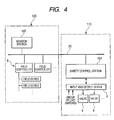
- Fig. 4 shows the structure of such a united system and a safety instrumentation system 110 and a distributed control system 120 are connected together through a communication line 30.
- a safety control station 101 is provided for carrying out a process to realize the safety of a plant.
- valves 4 are connected through an input and output device 3.
- a monitor station 107 is provided for monitoring field controllers 6 for controlling field devices and the entire part of the plant.
- the united structure of the safety instrumentation system and the control system is disclosed in, for instance, Japanese Patent Unexamined Publication No. 2006-164143 .
- the device of the safety instrumentation system 110 can be operated from the monitor station 107 of the distributed control system 120.
- the field controller 6 for originally controlling the field device may be possibly assigned to the operation of the device of the safety instrumentation system.
- data of the valve 4 treated in the safety control station 101 of the safety instrumentation system 110 is coordinated with data treated in the field controller 6.
- a communication function between the safety control station 101 and the field controller 6 is added. Therefore, the device such as the valve 4 of the safety instrumentation system 110 can be operated from the monitor station107 in the same method as that of the operation to the field device.
- Exemplary embodiments of the present invention provide a safety instrumentation system that can operate a device of a safety instrumentation system side through a plant control system by suppressing a burden of engineering, and a plant safety system including the safety instrumentation system and the plant control system.
- a safety instrumentation system of one or more embodiments of the present invention is connected to a plant control system.
- One or more embodiments of the safety instrumentation system comprises: a receiving unit that receives an instruction of an operation to a device of the safety instrumentation system through an instruction receiving part for receiving an instruction of an operation to a field device of the plant control system; an instruction converting unit that converts the data form of the instruction of the operation received by the receiving unit to the data form of the safety instrumentation system from the data form of the plant control system so that the instruction received by the receiving unit can be used as the instruction of the operation to the device of the safety instrumentation system; and an operation carrying out unit that receives the instruction of the operation obtained from the instruction converting unit and an original instruction of the safety instrumentation system to carry out the operations, and preferentially carries out the operation of the original instruction of the safety instrumentation system when both the instructions compete with each other, and is characterized in that the instruction converting unit and the operation carrying out unit are formed by using a function block mounted on the safety instrumentation system.
- a certifying unit may be provided that certifies a user.
- the safety instrumentation system of the present invention may include a display unit that displays, in the plant control system, the state of the field device of the plant control system; and a state converting unit that converts the data form of data showing the state of the device of the safety instrumentation system to the data form of the plant control system from the data form of the safety instrumentation system so that the state of the device of the safety instrumentation system can be displayed by the display unit.
- the device of the safety instrumentation system may be a valve that carries out a shut down in a plant.
- One or more embodiments of the present invention may include one or more the following advantages. For example, since the instruction converting unit and the operation carrying out unit are formed by using a function block mounted on the safety instrumentation system, the burden of engineering can be suppressed. Other features and advantages may be apparent from the following detailed description, the accompanying drawings and the claims.
- FIG. 1 to 3 an exemplary embodiment of a safety instrumentation system according to the present invention will be described below.
- Fig. 1 is a block diagram showing a structure of a safety instrumentation system of an exemplary embodiment.
- the safety instrumentation system 10 of the exemplary embodiment is connected to a distributed control system 20 through a communication line 30.
- the distributed control system 20 includes field controllers 6, 6,.... distributed and arranged in a plant for controlling field devices 5, 5,...., a monitor station 7 for monitoring and controlling the field devices 5, 5,... through the field controllers 6, 6....,and a terminal device 8 for maintenance for maintaining and managing the distributed control system 20.
- the filed controllers 6, 6,..., the monitor station 7 and the terminal device 8 for maintenance are connected together through the communication line 30.
- operation output values MV to the field devices 5, 5..., and process values PV to the field devices 5, 5...are displayed. Further, the monitor station 7 functions as an instruction receiving part for receiving an instruction of an operation to the field devices 5, 5....
- the safety instrumentation system 10 includes a safety control station 1 for carrying out a process for maintaining the safety of the plant and a terminal device 2 for maintenance for maintaining and managing the safety instrumentation system 10.
- the safety control station 1 and the terminal device 2 for maintenance are connected to each other through the communication line 30.
- the safety control station 1 is connected to a group of limit switches or valves 4, 4,... through an input and output device 3.
- the monitor station 7 of the distributed control system 20 includes a receiving unit 71 for receiving an instruction of an operation to the devices of the plant safety instrumentation system and a display unit 72 for displaying the states of the field devices 5, 5,... of the plant control system 20.
- the safety control station 1 of the safety instrumentation system 10 includes an instruction converting unit 11; an operation carrying out unit 12; a certifying unit 13; and a state converting unit 14.
- the instruction converting unit 11 converts the data form of the instruction of the operation received by the receiving unit 71 to the data form of the safety instrumentation system 10 from the data form of the plant control system 20 so that the instruction received by the receiving unit 71 can be used as the instruction of the operation to the device of the safety instrumentation system 10.
- the operation carrying out unit 12 receives the instruction of the operation obtained by the instruction converting unit 11 and an original instruction of the safety instrumentation system 10 to carry out the operations, and preferentially carries out the operation of the original instruction of the safety instrumentation system 10 when both the instructions compete with each other.
- the certifying unit 13 certifies a user when the instruction of the operation is received by the receiving unit 71.
- the state converting unit 14 converts the data form of data showing the state of the device of the safety instrumentation system 10 to the data form of the plant control system 20 from the data form of the safety instrumentation system 10 so that the state of the device of the safety instrumentation system 10 can be displayed by the display unit 72.
- Fig. 2 is a diagram showing a function block and a map block mounted on the safety control station 1. As shown in Fig. 2, in the safety control station 1, a Boolean type manual operation function block 21 and a map block 22 are mounted relative to the various kinds of devices such as the valve 4.
- an operating procedure is defined that is related to a manual operation for the device of the safety instrumentation system.
- the instruction converting unit 11 and the operation carrying out unit 12 are formed by using the function block 21.
- a part of input and output elements of the function block 21 is omitted.
- a shut down input terminal (SHDN) of the function block 21 As shown in Fig. 2, to a shut down input terminal (SHDN) of the function block 21, a signal from a shut down logic mounted on the safety control station 1 is inputted.
- SHDN shut down input terminal
- a detecting signal of a limit switch for detecting the opening state of the valve 4 of the safety instrumentation system 10 is fetched as an input variable (ANSVAR1) of the safety control station 1 through the input and output device 3.
- the input variable (ANSVAR1) is inputted to an answer back input terminal (AINP) of the function block 21.
- a detecting signal of a limit switch for detecting the closing state of the valve 4 of the safety instrumentation system 10 is fetched as an input variable (ANSVAR2) of the safety control station 1 through the input and output device 3.
- the input variable (ANSVAR2) is inputted to an answer back input terminal (AINM) of the function block 21.
- An output terminal (OUT) of the function block 21 is connected to an output variable (OPVAR) supplied to the valve 4.
- the parameters of the map block 22 are supplied to the monitor station 7 of the distributed control system 20 through the communication line 30 and displayed on a monitor screen as a face plate 40 shown in Fig. 2 by the display unit 72. Further, an operation to the face plate 40 is supplied to the map block 22 through the receiving unit 71 and the communication line 30 and reflected on the parameters.
- the structure of the face plate 40 is the same as the structure of a face plate for operating and monitoring the field device 5 of the distributed control system 20, so that an operator can operate the device of the safety instrumentation system with the same sense as that of an operation to the field device 5.
- a display area 41 of a tag name corresponding to the valve 4 a display area 42 of a process value (PV) and an operation output value (MV) of the valve 4, buttons 43a and 43b for displaying the process value (PV) and buttons 44a and 44b for receiving the input of the operation output value (MV) are provided.
- the operator can change the operation output value (MV) by operating the button 44a or 44b.
- the operation of the operator is reflected on the contents of the display of the display area 42.
- the operation for changing the operation output value (MV) is supplied to the safety control station 1 through the receiving unit 71 and the communication line 30 to instruct the map block 22 to change the operation output value (MV).
- the changed value is transferred to the output variable (OPVAR) outputted from the output terminal (OUT) of the function block 21.
- the output variable (OPVAR) is outputted to the valve 4 through the input and output device 3.
- the opening/closing state of the valve 4 is fetched to the function block 21 as the input variable (ANSVAR1) or the input variable (ANSVAR2) based on the detecting signal of the limit switch and converted to the process value (PV).
- the process value (PV) of the function block 21 is reflected on the map block 22 and supplied to the monitor station 7 of the distributed control system 20 through the communication line 30.
- the display unit 72 reflects the supplied process value (PV) on a display in the display area 42 and the buttons 43a and 43b of the face plate 40.
- the operator compares the operation output value (MV) with the process value (PV) displayed on the face plate 40 so that the operator can recognize whether or not the operation to the operation output value (MV) is properly transmitted to the valve 4 to be operated.
- the function block 21 outputs the output variable (OPVAR) determined by the application software of the safety instrumentation system from the output terminal (OUT) preferentially to the operation to the operation output value (MV) through the face plate 40.
- OOVAR output variable
- SHDN shut down input terminal
- the operator is certified by the certifying unit 13.
- the operator is requested to input a password and the inputted password is supplied to the safety control station 1 through the communication line 30.
- the inputted password is collated with a password of a password input terminal (PSWD) of the function block 21. Only when the passwords correspond to each other, the function block 21 receives the change of the operation output value (MV). Thus, a right for operating the valve 4 can be given only to a specific person.
- PSWD password input terminal
- the device of the safety instrumentation system 10 can be operated through the monitor station 7 of the distributed control system 20 like the field device 5 of the distributed control system 20. Further, an algorithm for realizing the above-described operation is described by the function block of the safety instrumentation system 10 side. Accordingly, a description by the application software of the distributed control system 20 side is not required, so that an engineering cost and an engineering burden can be extremely suppressed.
- Fig. 3 is a diagram showing a function block and a map block when an analog valve is used as a device of the safety instrumentation system.
- an analog type manual operation function block 21A and a map block 22A are respectively mounted relative to analog valves.
- an operating procedure is defined that is related to a manual operation for the analog valve.
- the instruction converting unit 11 and the operation carrying out unit 12 are formed by using the function block 21A.
- a part of input and output elements of the function block 21A is omitted.
- a shut down input terminal (SHDN) of the function block 21A As shown in Fig. 3, to a shut down input terminal (SHDN) of the function block 21A, a signal from a shut down logic mounted on the safety control station 1 is inputted.
- SHDN shut down input terminal
- a signal of an aperture sensor of the analog valve is fetched as an input variable (FVVAR1) through the input and output device 3.
- the input variable (FVVAR1) is inputted to a feedback input terminal (FV) of the function block 21A.
- An output terminal (OUT) of the function block 21A is connected to an output variable (OPVAR) supplied to the analog valve.
- the parameters of the map block 22A are supplied to the monitor station 7 of the distributed control system 20 through the communication line 30 and displayed on a monitor screen as a face plate 50 shown in Fig. 3 by the display unit 72. Further, an operation to the face plate 50 is supplied to the map block 22A through the receiving unit 71 and the communication line 30 and reflected on the parameters.
- the structure of the face plate 50 is the same as the structure of a face plate for operating and monitoring the field device 5 of the distributed control system 20, so that an operator can operate the device of the safety instrumentation system with the same sense as that of an operation to the field device 5.
- a display area 51 of a tag name corresponding to the analog valve a display area 52 of a feedback value (FV) showing the opening degree of the analog valve and an operation output value (MV), an area 53 for displaying the feedback value (FV) and an area 54 for receiving an input of the operation output value (MV) are provided.
- FV feedback value
- MV operation output value
- An operator can change the operation output value (MV) by operating the area 54.
- the operation of the operator is reflected on the contents of the display of the display area 52.
- the operation for changing the operation output value (MV) is supplied to the safety control station 1 through the receiving unit 71 and the communication line 30 to instruct the map block 22A to change the operation output value (MV) .
- the changed value is transferred to the output variable (OPVAR) outputted from the output terminal (OUT)of the function block 21A.
- the output variable (OPVAR) is outputted to the analog valve through the input and output device 3.
- the opening degree or aperture of the analog valve is fetched to the function block 21A as the input variable (FVVAR1) and reflected on the feedback value (FV).
- the feedback value (FV) of the function block 21A is reflected on the map block 22A and supplied to the monitor station 7 of the distributed control system 20 through the communication line 30.
- the display unit 72 reflects the supplied feedback value (FV) on a display in the display area 52 and the display area 53 of the face plate 50.
- the operator compares the operation output value (MV) with the feedback value (FV) displayed on the face plate 50 so that the operator can recognize whether or not the operation to the operation output value (MV) is properly transmitted to the analog valve to be operated.
- the function block 21A outputs the output variable (OPVAR) determined by the application software of the safety instrumentation system from the output terminal (OUT) preferentially to the operation to the operation output value (MV) through the face plate 50.
- OOVAR output variable
- SHDN shut down input terminal
- a shut down output value is outputted from the output terminal (OUT) irrespective of the operation by the face plate 50.
- the operator is certified by the certifying unit 13.
- the operator is requested to input a password and the inputted password is supplied to the safety control station 1 through the communication line 30.
- the inputted password is collated with a password of a password input terminal (PSWD) of the function block 21A. Only when the passwords correspond to each other, the function block 21A receives the change of the operation output value (MV) . Thus, a right for operating the analog valve can be given only to a specific person.
- PSWD password input terminal
- the analog valve of the safety instrumentation system can be operated through the monitor station 7 of the distributed control system 20 like the field device 5 of the distributed control system 20. Further, an algorithm for realizing the above-described operation is described by the function block of the safety instrumentation system side. Accordingly, a description by the application software of the distributed control system 20 side is not required, so that an engineering cost and an engineering burden can be extremely suppressed.
- An applied range of the present invention is not limited to the above-described exemplary embodiment.
- the present invention can be widely applied to the safety instrumentation system connected to the plant control system. While the present invention has been described with respect to a limited number of embodiments, those skilled in the art, having benefit of this disclosure, will appreciate that other embodiments can be devised which do not depart from the scope of the present invention as disclosed herein. Accordingly, the scope of the present invention should be limited only by the attached claims.
Landscapes
- Engineering & Computer Science (AREA)
- Physics & Mathematics (AREA)
- General Physics & Mathematics (AREA)
- Automation & Control Theory (AREA)
- General Engineering & Computer Science (AREA)
- Manufacturing & Machinery (AREA)
- Quality & Reliability (AREA)
- Safety Devices In Control Systems (AREA)
Abstract
Description
- This application claims priority to
Japanese Patent Application No. 2006-217653, filed August 10, 2006 - The present disclosure relates to a safety instrumentation system connected to a plant control system, and a plant safety system including the safety instrumentation system and the plant control system, and more particularly to a safety instrumentation system that can construct a unified environment.
- A safety instrumentation system aiming to ensure the safety of a plant has been known. The safety instrumentation system is provided as a separate system independent of the plant control system for controlling the field device of the plant so that the safety instrumentation system can assuredly operate to ensure a safety.
- On the other hand, in order to improve operability, a technique for uniting the plant control system with the safety instrumentation system has been developed. In order to unite these systems with each other, both the systems are connected together by a common communication line to achieve a communication between the systems. Fig. 4 shows the structure of such a united system and a
safety instrumentation system 110 and adistributed control system 120 are connected together through acommunication line 30. In thesafety instrumentation system 110, asafety control station 101 is provided for carrying out a process to realize the safety of a plant. To thesafety control station 101,valves 4 are connected through an input andoutput device 3. Further, in thedistributed control system 120, amonitor station 107 is provided for monitoringfield controllers 6 for controlling field devices and the entire part of the plant. - The united structure of the safety instrumentation system and the control system is disclosed in, for instance,
Japanese Patent Unexamined Publication No. 2006-164143 - As shown in Fig. 4, when the
distributed control system 120 and thesafety instrumentation system 110 are connected to each other, the device of thesafety instrumentation system 110 can be operated from themonitor station 107 of thedistributed control system 120. For instance, thefield controller 6 for originally controlling the field device may be possibly assigned to the operation of the device of the safety instrumentation system. In such a method, data of thevalve 4 treated in thesafety control station 101 of thesafety instrumentation system 110 is coordinated with data treated in thefield controller 6. Further, a communication function between thesafety control station 101 and thefield controller 6 is added. Therefore, the device such as thevalve 4 of thesafety instrumentation system 110 can be operated from the monitor station107 in the same method as that of the operation to the field device. - However, it requires a troublesome operation to coordinate the data of the
safety control station 101 with the data of the filedcontroller 6. Thus, this operation imposes a burden on engineering. Further, the contents of the operation or the monitor to the device of the safety instrumentation system are restricted by the original function of thefield controller 6. For instance, whether or not the contents of the operation are properly reflected on the state of the device cannot be recognized. Further, it is difficult to construct an arrangement for ensuring the assuredness and safety of an operation to be required for thesafety instrumentation system 110. - Exemplary embodiments of the present invention provide a safety instrumentation system that can operate a device of a safety instrumentation system side through a plant control system by suppressing a burden of engineering, and a plant safety system including the safety instrumentation system and the plant control system.
- A safety instrumentation system of one or more embodiments of the present invention is connected to a plant control system. One or more embodiments of the safety instrumentation system comprises: a receiving unit that receives an instruction of an operation to a device of the safety instrumentation system through an instruction receiving part for receiving an instruction of an operation to a field device of the plant control system; an instruction converting unit that converts the data form of the instruction of the operation received by the receiving unit to the data form of the safety instrumentation system from the data form of the plant control system so that the instruction received by the receiving unit can be used as the instruction of the operation to the device of the safety instrumentation system; and an operation carrying out unit that receives the instruction of the operation obtained from the instruction converting unit and an original instruction of the safety instrumentation system to carry out the operations, and preferentially carries out the operation of the original instruction of the safety instrumentation system when both the instructions compete with each other, and is characterized in that the instruction converting unit and the operation carrying out unit are formed by using a function block mounted on the safety instrumentation system.
According to this safety instrumentation system, since the instruction converting unit and the operation carrying out unit are formed by using the function block mounted on the safety instrumentation system, the burden of engineering can be suppressed. - When the instruction of the operation is received by the receiving unit, a certifying unit may be provided that certifies a user.
- The safety instrumentation system of the present invention may include a display unit that displays, in the plant control system, the state of the field device of the plant control system; and a state converting unit that converts the data form of data showing the state of the device of the safety instrumentation system to the data form of the plant control system from the data form of the safety instrumentation system so that the state of the device of the safety instrumentation system can be displayed by the display unit.
- The device of the safety instrumentation system may be a valve that carries out a shut down in a plant.
- One or more embodiments of the present invention may include one or more the following advantages. For example, since the instruction converting unit and the operation carrying out unit are formed by using a function block mounted on the safety instrumentation system, the burden of engineering can be suppressed.
Other features and advantages may be apparent from the following detailed description, the accompanying drawings and the claims. -
- Fig. 1 is a block diagram showing the structure of a safety instrumentation system of an exemplary embodiment of the present invention.
- Fig. 2 is a diagram showing a function block and a map block mounted on a safety control station.
- Fig. 3 is a diagram showing a function block and a map block when an analog valve is used as a device of the safety instrumentation system.
- Fig. 4 is a block diagram showing the structure of a safety instrumentation system connected to a plant control system.
- Now, referring to Figs. 1 to 3, an exemplary embodiment of a safety instrumentation system according to the present invention will be described below.
- Fig. 1 is a block diagram showing a structure of a safety instrumentation system of an exemplary embodiment.
- As shown in Fig. 1, the
safety instrumentation system 10 of the exemplary embodiment is connected to adistributed control system 20 through acommunication line 30. - The
distributed control system 20 includesfield controllers field devices monitor station 7 for monitoring and controlling thefield devices field controllers terminal device 8 for maintenance for maintaining and managing thedistributed control system 20. The filedcontrollers monitor station 7 and theterminal device 8 for maintenance are connected together through thecommunication line 30. - In the
monitor station 7, operation output values MV to thefield devices field devices monitor station 7 functions as an instruction receiving part for receiving an instruction of an operation to thefield devices - The
safety instrumentation system 10 includes asafety control station 1 for carrying out a process for maintaining the safety of the plant and aterminal device 2 for maintenance for maintaining and managing thesafety instrumentation system 10. Thesafety control station 1 and theterminal device 2 for maintenance are connected to each other through thecommunication line 30. - Further, the
safety control station 1 is connected to a group of limit switches orvalves output device 3. - As shown in Fig. 1, the
monitor station 7 of thedistributed control system 20 includes a receivingunit 71 for receiving an instruction of an operation to the devices of the plant safety instrumentation system and adisplay unit 72 for displaying the states of thefield devices plant control system 20. - Further, the
safety control station 1 of thesafety instrumentation system 10 includes an instruction converting unit 11; an operation carrying outunit 12; acertifying unit 13; and astate converting unit 14. The instruction converting unit 11 converts the data form of the instruction of the operation received by the receivingunit 71 to the data form of thesafety instrumentation system 10 from the data form of theplant control system 20 so that the instruction received by the receivingunit 71 can be used as the instruction of the operation to the device of thesafety instrumentation system 10. The operation carrying outunit 12 receives the instruction of the operation obtained by the instruction converting unit 11 and an original instruction of thesafety instrumentation system 10 to carry out the operations, and preferentially carries out the operation of the original instruction of thesafety instrumentation system 10 when both the instructions compete with each other. Thecertifying unit 13 certifies a user when the instruction of the operation is received by thereceiving unit 71. Thestate converting unit 14 converts the data form of data showing the state of the device of thesafety instrumentation system 10 to the data form of theplant control system 20 from the data form of thesafety instrumentation system 10 so that the state of the device of thesafety instrumentation system 10 can be displayed by thedisplay unit 72. - Fig. 2 is a diagram showing a function block and a map block mounted on the
safety control station 1. As shown in Fig. 2, in thesafety control station 1, a Boolean type manualoperation function block 21 and amap block 22 are mounted relative to the various kinds of devices such as thevalve 4. - In the
function block 21, an operating procedure is defined that is related to a manual operation for the device of the safety instrumentation system. The instruction converting unit 11 and the operation carrying outunit 12 are formed by using thefunction block 21. In Fig. 2, a part of input and output elements of thefunction block 21 is omitted. - As shown in Fig. 2, to a shut down input terminal (SHDN) of the
function block 21, a signal from a shut down logic mounted on thesafety control station 1 is inputted. - A detecting signal of a limit switch for detecting the opening state of the
valve 4 of thesafety instrumentation system 10 is fetched as an input variable (ANSVAR1) of thesafety control station 1 through the input andoutput device 3. The input variable (ANSVAR1) is inputted to an answer back input terminal (AINP) of thefunction block 21. - A detecting signal of a limit switch for detecting the closing state of the
valve 4 of thesafety instrumentation system 10 is fetched as an input variable (ANSVAR2) of thesafety control station 1 through the input andoutput device 3. The input variable (ANSVAR2) is inputted to an answer back input terminal (AINM) of thefunction block 21. - An output terminal (OUT) of the
function block 21 is connected to an output variable (OPVAR) supplied to thevalve 4. - To the
map block 22, parameters of thefunction block 21 are respectively transferred. - The parameters of the
map block 22 are supplied to themonitor station 7 of the distributedcontrol system 20 through thecommunication line 30 and displayed on a monitor screen as aface plate 40 shown in Fig. 2 by thedisplay unit 72. Further, an operation to theface plate 40 is supplied to themap block 22 through the receivingunit 71 and thecommunication line 30 and reflected on the parameters. The structure of theface plate 40 is the same as the structure of a face plate for operating and monitoring thefield device 5 of the distributedcontrol system 20, so that an operator can operate the device of the safety instrumentation system with the same sense as that of an operation to thefield device 5. - As shown in Fig. 2, in the
face plate 40, adisplay area 41 of a tag name corresponding to thevalve 4, adisplay area 42 of a process value (PV) and an operation output value (MV) of thevalve 4,buttons buttons - Now, an operation carried out when the
valve 4 of thesafety instrumentation system 10 is operated by using theface plate 40 will be described below. - The operator can change the operation output value (MV) by operating the
button display area 42. The operation for changing the operation output value (MV) is supplied to thesafety control station 1 through the receivingunit 71 and thecommunication line 30 to instruct themap block 22 to change the operation output value (MV). When the operation output value (MV) of themap block 22 is changed, the changed value is transferred to the output variable (OPVAR) outputted from the output terminal (OUT) of thefunction block 21. The output variable (OPVAR) is outputted to thevalve 4 through the input andoutput device 3. - The opening/closing state of the
valve 4 is fetched to thefunction block 21 as the input variable (ANSVAR1) or the input variable (ANSVAR2) based on the detecting signal of the limit switch and converted to the process value (PV). The process value (PV) of thefunction block 21 is reflected on themap block 22 and supplied to themonitor station 7 of the distributedcontrol system 20 through thecommunication line 30. Thedisplay unit 72 reflects the supplied process value (PV) on a display in thedisplay area 42 and thebuttons face plate 40. - Accordingly, the operator compares the operation output value (MV) with the process value (PV) displayed on the
face plate 40 so that the operator can recognize whether or not the operation to the operation output value (MV) is properly transmitted to thevalve 4 to be operated. - In the safety instrumentation system of the exemplary embodiment, the
function block 21 outputs the output variable (OPVAR) determined by the application software of the safety instrumentation system from the output terminal (OUT) preferentially to the operation to the operation output value (MV) through theface plate 40. When the signal inputted to the shut down input terminal (SHDN) of thefunction block 21 corresponds to a specific condition, a shut down output value is outputted from the output terminal (OUT) irrespective of the operation by theface plate 40. - Accordingly, for instance, even when an operation of the safety instrumentation system is temporarily released to operate the
valve 4 during starting or maintaining the plant, if a new shut down phenomenon arises, the operation to theface plate 40 is neglected to assuredly shut down the plant. Therefore, when the device of the safety instrumentation system is manually operated, an unexpected situation can be avoided. - Further, in the safety instrumentation system of the exemplary embodiment, during the operation of the operation output value (MV) through the
face plate 40, the operator is certified by the certifyingunit 13. During the operation of the operation output value (MV), the operator is requested to input a password and the inputted password is supplied to thesafety control station 1 through thecommunication line 30. - The inputted password is collated with a password of a password input terminal (PSWD) of the
function block 21. Only when the passwords correspond to each other, thefunction block 21 receives the change of the operation output value (MV). Thus, a right for operating thevalve 4 can be given only to a specific person. - As described above, according to the safety instrumentation system of the exemplary embodiment, the device of the
safety instrumentation system 10 can be operated through themonitor station 7 of the distributedcontrol system 20 like thefield device 5 of the distributedcontrol system 20. Further, an algorithm for realizing the above-described operation is described by the function block of thesafety instrumentation system 10 side. Accordingly, a description by the application software of the distributedcontrol system 20 side is not required, so that an engineering cost and an engineering burden can be extremely suppressed. - Fig. 3 is a diagram showing a function block and a map block when an analog valve is used as a device of the safety instrumentation system. As shown in Fig. 3, in the
safety control station 1, an analog type manualoperation function block 21A and amap block 22A are respectively mounted relative to analog valves. - In the
function block 21A, an operating procedure is defined that is related to a manual operation for the analog valve. The instruction converting unit 11 and the operation carrying outunit 12 are formed by using thefunction block 21A. In Fig. 3, a part of input and output elements of thefunction block 21A is omitted. - As shown in Fig. 3, to a shut down input terminal (SHDN) of the
function block 21A, a signal from a shut down logic mounted on thesafety control station 1 is inputted. - A signal of an aperture sensor of the analog valve is fetched as an input variable (FVVAR1) through the input and
output device 3. The input variable (FVVAR1) is inputted to a feedback input terminal (FV) of thefunction block 21A. - An output terminal (OUT) of the
function block 21A is connected to an output variable (OPVAR) supplied to the analog valve. - To the
map block 22A, parameters of thefunction block 21A are respectively transferred. - The parameters of the
map block 22A are supplied to themonitor station 7 of the distributedcontrol system 20 through thecommunication line 30 and displayed on a monitor screen as aface plate 50 shown in Fig. 3 by thedisplay unit 72. Further, an operation to theface plate 50 is supplied to themap block 22A through the receivingunit 71 and thecommunication line 30 and reflected on the parameters. The structure of theface plate 50 is the same as the structure of a face plate for operating and monitoring thefield device 5 of the distributedcontrol system 20, so that an operator can operate the device of the safety instrumentation system with the same sense as that of an operation to thefield device 5. - As shown in Fig. 3, in the
face plate 50, adisplay area 51 of a tag name corresponding to the analog valve, adisplay area 52 of a feedback value (FV) showing the opening degree of the analog valve and an operation output value (MV), anarea 53 for displaying the feedback value (FV) and anarea 54 for receiving an input of the operation output value (MV) are provided. - Now, an operation carried out when the analog valve of the safety instrumentation system is operated by using the
face plate 50 will be described below. - An operator can change the operation output value (MV) by operating the
area 54. The operation of the operator is reflected on the contents of the display of thedisplay area 52. The operation for changing the operation output value (MV) is supplied to thesafety control station 1 through the receivingunit 71 and thecommunication line 30 to instruct the map block 22A to change the operation output value (MV) . When the operation output value (MV) of themap block 22A is changed, the changed value is transferred to the output variable (OPVAR) outputted from the output terminal (OUT)of thefunction block 21A. The output variable (OPVAR) is outputted to the analog valve through the input andoutput device 3. - The opening degree or aperture of the analog valve is fetched to the
function block 21A as the input variable (FVVAR1) and reflected on the feedback value (FV). The feedback value (FV) of thefunction block 21A is reflected on themap block 22A and supplied to themonitor station 7 of the distributedcontrol system 20 through thecommunication line 30. Thedisplay unit 72 reflects the supplied feedback value (FV) on a display in thedisplay area 52 and thedisplay area 53 of theface plate 50. - Accordingly, the operator compares the operation output value (MV) with the feedback value (FV) displayed on the
face plate 50 so that the operator can recognize whether or not the operation to the operation output value (MV) is properly transmitted to the analog valve to be operated. - In the safety instrumentation system of the exemplary embodiment, the
function block 21A outputs the output variable (OPVAR) determined by the application software of the safety instrumentation system from the output terminal (OUT) preferentially to the operation to the operation output value (MV) through theface plate 50. When the signal inputted to the shut down input terminal (SHDN) of thefunction block 21A corresponds to a specific condition, a shut down output value is outputted from the output terminal (OUT) irrespective of the operation by theface plate 50. - Accordingly, for instance, even when an operation of the safety instrumentation system is temporarily released to operate the analog valve during starting or maintaining the plant, if a new shut down phenomenon arises, the operation to the
face plate 50 is neglected to assuredly shut down the plant. Therefore, when the device of the safety instrumentation system is manually operated, an unexpected situation can be avoided. - Further, in the safety instrumentation system of the exemplary embodiment, during the operation of the operation output value (MV) through the
face plate 50, the operator is certified by the certifyingunit 13. During the operation of the operation output value (MV), the operator is requested to input a password and the inputted password is supplied to thesafety control station 1 through thecommunication line 30. - The inputted password is collated with a password of a password input terminal (PSWD) of the
function block 21A. Only when the passwords correspond to each other, thefunction block 21A receives the change of the operation output value (MV) . Thus, a right for operating the analog valve can be given only to a specific person. - As described above, the analog valve of the safety instrumentation system can be operated through the
monitor station 7 of the distributedcontrol system 20 like thefield device 5 of the distributedcontrol system 20. Further, an algorithm for realizing the above-described operation is described by the function block of the safety instrumentation system side. Accordingly, a description by the application software of the distributedcontrol system 20 side is not required, so that an engineering cost and an engineering burden can be extremely suppressed. - An applied range of the present invention is not limited to the above-described exemplary embodiment. The present invention can be widely applied to the safety instrumentation system connected to the plant control system.
While the present invention has been described with respect to a limited number of embodiments, those skilled in the art, having benefit of this disclosure, will appreciate that other embodiments can be devised which do not depart from the scope of the present invention as disclosed herein. Accordingly, the scope of the present invention should be limited only by the attached claims.
Claims (8)
- A safety instrumentation system connected to a plant control system, said safety instrumentation system comprising:a receiving unit that receives an instruction of an operation to a device of the safety instrumentation system through an instruction receiving part for receiving an instruction of an operation to a field device of the plant control system;an instruction converting unit that converts the data form of the instruction of the operation received by the receiving unit to the data form of the safety instrumentation system from the data form of the plant control system so that the instruction received by the receiving unit can be used as the instruction of the operation to the device of the safety instrumentation system; andan operation carrying out unit that receives the instruction of the operation obtained from the instruction converting unit and an original instruction of the safety instrumentation system to carry out the operations, and preferentially carries out the operation of the original instruction of the safety instrumentation system when both the instructions compete with each other,wherein the instruction converting unit and the operation carrying out unit are formed by using a function block mounted on the safety instrumentation system.
- A safety instrumentation system according to claim 1, further comprising:a certifying unit that certifies a user when the instruction of the operation is received by the receiving unit.
- A safety instrumentation systemaccording to claim 1 or 2, further comprising:a display unit that displays, in the plant control system, the state of the field device of the plant control system; anda state converting unit that converts the data form of data showing the state of the device of the safety instrumentation system to the data form of the plant control system from the data form of the safety instrumentation system so that the state of the device of the safety instrumentation system can be displayed by the display unit.
- A safety instrumentation system according to any one of claims 1 to 3, wherein the device of the safety instrumentation system is a valve that carries out a shut down in a plant.
- A plant safety system comprising;a plant control system; anda safety instrumentation system connected to the plant control system through a communication line,wherein the plant control system includes an instruction receiving part that receives an instruction of an operation to a field device of the plant control system,
wherein the safety instrumentation system includes a receiving unit that receives an instruction of an operation to a device of the safety instrumentation system through the instruction receiving part of the plant control system, an instruction converting unit that converts the data form of the instruction of the operation received by the receiving unit to the data form of the safety instrumentation system from the data form of the plant control system so that the instruction received by the receiving unit can be used as the instruction of the operation to the device of the safety instrumentation system, and an operation carrying out unit that receives the instruction of the operation obtained from the instruction converting unit and an original instruction of the safety instrumentation system to carry out the operations, and preferentially carries out the operation of the original instruction of the safety instrumentation system when both the instructions compete with each other,
wherein the instruction converting unit and the operation carrying out unit are formed by using a function block mounted on the safety instrumentation system. - A plant safety system according to claim 5, wherein the safety instrumentation system further includes a certifying unit that certifies a user when the instruction of the operation is received by the receiving unit.
- A plant safety system according to claim 5 or 6, wherein the plant control system further includes a display unit that displays the state of the field device of the plant control system, and the safety instrumentation system further includes a state converting unit that converts the data form of data showing the state of the device of the safety instrumentation system to the data form of the plant control system from the data form of the safety instrumentation system so that the state of the device of the safety instrumentation system can be displayed by the display unit.
- A plant safety system according to any one of claims 5 to 7, wherein the device of the safety instrumentation system is a valve that carries out a shut down in a plant.
Applications Claiming Priority (1)
| Application Number | Priority Date | Filing Date | Title |
|---|---|---|---|
| JP2006217653A JP4671131B2 (en) | 2006-08-10 | 2006-08-10 | Safety instrumentation system |
Publications (3)
| Publication Number | Publication Date |
|---|---|
| EP1887447A2 true EP1887447A2 (en) | 2008-02-13 |
| EP1887447A3 EP1887447A3 (en) | 2010-01-27 |
| EP1887447B1 EP1887447B1 (en) | 2018-04-25 |
Family
ID=38819414
Family Applications (1)
| Application Number | Title | Priority Date | Filing Date |
|---|---|---|---|
| EP07014449.8A Not-in-force EP1887447B1 (en) | 2006-08-10 | 2007-07-23 | Safety instrumentation system and plant safety system |
Country Status (4)
| Country | Link |
|---|---|
| US (1) | US8024053B2 (en) |
| EP (1) | EP1887447B1 (en) |
| JP (1) | JP4671131B2 (en) |
| CN (1) | CN100520654C (en) |
Cited By (3)
| Publication number | Priority date | Publication date | Assignee | Title |
|---|---|---|---|---|
| WO2010039804A1 (en) | 2008-09-30 | 2010-04-08 | Saudi Arabian Oil Company | System and method for improved coordination between control and safety systems |
| EP2372481A3 (en) * | 2010-03-29 | 2012-03-07 | Yokogawa Electric Corporation | Operational state analysis system and operational state analysis method |
| WO2016079018A1 (en) * | 2014-11-18 | 2016-05-26 | Schneider Electric Automation Gmbh | Method for accessing functions of an embedded device |
Families Citing this family (8)
| Publication number | Priority date | Publication date | Assignee | Title |
|---|---|---|---|---|
| JP5091308B2 (en) * | 2008-04-09 | 2012-12-05 | 三菱電機株式会社 | Graphic user interface device |
| US7869889B2 (en) * | 2008-07-02 | 2011-01-11 | Saudi Arabian Oil Company | Distributed and adaptive smart logic with multi-communication apparatus for reliable safety system shutdown |
| US8285402B2 (en) * | 2008-07-14 | 2012-10-09 | Ge Intelligent Platforms, Inc. | Method and system for safety monitored terminal block |
| DE102008060005A1 (en) * | 2008-11-25 | 2010-06-10 | Pilz Gmbh & Co. Kg | A safety controller and method for controlling an automated plant having a plurality of plant hardware components |
| JP5013493B2 (en) * | 2010-03-04 | 2012-08-29 | オムロン株式会社 | Valve control system and valve control method |
| EP2937745B1 (en) * | 2014-04-25 | 2016-10-05 | Sick Ag | Safety control system for safe operation of a technical installation and method for operating the safety control system |
| JP6296068B2 (en) | 2016-01-15 | 2018-03-20 | 横河電機株式会社 | Monitoring control system and work support method |
| JP6816553B2 (en) * | 2017-02-21 | 2021-01-20 | オムロン株式会社 | Control system |
Citations (1)
| Publication number | Priority date | Publication date | Assignee | Title |
|---|---|---|---|---|
| US5278480A (en) | 1992-10-26 | 1994-01-11 | Stanley Home Automation | Door opener control with adaptive limits and method therefor |
Family Cites Families (15)
| Publication number | Priority date | Publication date | Assignee | Title |
|---|---|---|---|---|
| US4638433A (en) * | 1984-05-30 | 1987-01-20 | Chamberlain Manufacturing Corporation | Microprocessor controlled garage door operator |
| JPS6459401A (en) * | 1987-08-31 | 1989-03-07 | Hitachi Ltd | Deep layer protection type controller |
| JP3070653B2 (en) * | 1994-02-08 | 2000-07-31 | 横河電機株式会社 | Plant monitoring equipment |
| DE19707241C2 (en) * | 1997-02-25 | 2000-05-31 | Pilz Gmbh & Co | Modular safety relay |
| US6647301B1 (en) * | 1999-04-22 | 2003-11-11 | Dow Global Technologies Inc. | Process control system with integrated safety control system |
| DE10020075C5 (en) * | 2000-04-22 | 2011-06-22 | Pilz GmbH & Co. KG, 73760 | Safety switching device module arrangement |
| US7289861B2 (en) * | 2003-01-28 | 2007-10-30 | Fisher-Rosemount Systems, Inc. | Process control system with an embedded safety system |
| US6975966B2 (en) * | 2003-01-28 | 2005-12-13 | Fisher-Rosemount Systems, Inc. | Integrated diagnostics in a process plant having a process control system and a safety system |
| US7330768B2 (en) * | 2003-01-28 | 2008-02-12 | Fisher-Rosemount Systems, Inc. | Integrated configuration in a process plant having a process control system and a safety system |
| US6898468B2 (en) * | 2003-03-28 | 2005-05-24 | Fisher-Rosemount Systems, Inc. | Function block implementation of a cause and effect matrix for use in a process safety system |
| EP1465029B1 (en) * | 2003-04-01 | 2006-06-14 | Festo AG & Co | Control device, control module, module array and control system |
| EP1513076A1 (en) * | 2003-09-05 | 2005-03-09 | Sap Ag | Method and computer system for data conversion |
| US7730415B2 (en) * | 2003-09-05 | 2010-06-01 | Fisher-Rosemount Systems, Inc. | State machine function block with a user modifiable state transition configuration database |
| US20050109395A1 (en) * | 2003-11-25 | 2005-05-26 | Seberger Steven G. | Shut down apparatus and method for use with electro-pneumatic controllers |
| JP2006164143A (en) * | 2004-12-10 | 2006-06-22 | Yokogawa Electric Corp | Plant control system |
-
2006
- 2006-08-10 JP JP2006217653A patent/JP4671131B2/en not_active Expired - Fee Related
-
2007
- 2007-07-23 EP EP07014449.8A patent/EP1887447B1/en not_active Not-in-force
- 2007-08-06 US US11/890,447 patent/US8024053B2/en active Active
- 2007-08-09 CN CNB2007101429156A patent/CN100520654C/en not_active Expired - Fee Related
Patent Citations (1)
| Publication number | Priority date | Publication date | Assignee | Title |
|---|---|---|---|---|
| US5278480A (en) | 1992-10-26 | 1994-01-11 | Stanley Home Automation | Door opener control with adaptive limits and method therefor |
Cited By (7)
| Publication number | Priority date | Publication date | Assignee | Title |
|---|---|---|---|---|
| WO2010039804A1 (en) | 2008-09-30 | 2010-04-08 | Saudi Arabian Oil Company | System and method for improved coordination between control and safety systems |
| EP2345015A4 (en) * | 2008-09-30 | 2013-03-27 | Saudi Arabian Oil Co | System and method for improved coordination between control and safety systems |
| US8649888B2 (en) | 2008-09-30 | 2014-02-11 | Saudi Arabian Oil Company | System and method for improved coordination between control and safety systems |
| EP2372481A3 (en) * | 2010-03-29 | 2012-03-07 | Yokogawa Electric Corporation | Operational state analysis system and operational state analysis method |
| WO2016079018A1 (en) * | 2014-11-18 | 2016-05-26 | Schneider Electric Automation Gmbh | Method for accessing functions of an embedded device |
| EP3191902B1 (en) | 2014-11-18 | 2020-04-22 | Schneider Electric Automation GmbH | Method for accessing functions of an embedded device |
| US10867077B2 (en) | 2014-11-18 | 2020-12-15 | Schneider Electric Automation Gmbh | Method of accessing functions of an embedded device |
Also Published As
| Publication number | Publication date |
|---|---|
| JP4671131B2 (en) | 2011-04-13 |
| JP2008040998A (en) | 2008-02-21 |
| US8024053B2 (en) | 2011-09-20 |
| EP1887447B1 (en) | 2018-04-25 |
| US20080082184A1 (en) | 2008-04-03 |
| CN100520654C (en) | 2009-07-29 |
| CN101122797A (en) | 2008-02-13 |
| EP1887447A3 (en) | 2010-01-27 |
Similar Documents
| Publication | Publication Date | Title |
|---|---|---|
| US8024053B2 (en) | Safety instrumentation system and plant safety system | |
| US7184873B1 (en) | Vehicle speed limiting device | |
| US9417614B2 (en) | System for the central control of devices used during an operation | |
| US10478965B2 (en) | Robot system | |
| US6256556B1 (en) | Remote operation system for a robot | |
| US8005572B2 (en) | Flexible connection of teaching devices to programmable controllers | |
| US8250242B2 (en) | Field bus system | |
| JP2005063024A (en) | Failure diagnostic device | |
| US20100057221A1 (en) | Mobile control and monitoring system | |
| JP2005161486A (en) | Robot system | |
| JP2012230553A (en) | Monitoring controller and monitoring control method | |
| US20040260538A1 (en) | System and method for voice input to an automation system | |
| JP2002239953A (en) | Industrial robot | |
| US20080174542A1 (en) | Liquid crystal display device and method of controlling the same | |
| JPH0575320B2 (en) | ||
| JP3489498B2 (en) | Plant control system and communication destination switching method in auxiliary operation console | |
| JP4976726B2 (en) | Sensor system and sensor unit | |
| JP4328964B2 (en) | Range management method and range management apparatus | |
| JPH0885975A (en) | Radio control equipment for civil engineering and construction machinery | |
| JP4863212B2 (en) | Industrial vehicle integration device | |
| KR20150017412A (en) | Interface Apparatus for Operating Automatic System of Vessel | |
| JPH11161310A (en) | Remote control robot control system | |
| JP2005182257A (en) | Inching control method | |
| KR20030089682A (en) | self system for diagnosing building automatic controller and method thereof | |
| JP2013134576A (en) | Plant control system |
Legal Events
| Date | Code | Title | Description |
|---|---|---|---|
| PUAI | Public reference made under article 153(3) epc to a published international application that has entered the european phase |
Free format text: ORIGINAL CODE: 0009012 |
|
| AK | Designated contracting states |
Kind code of ref document: A2 Designated state(s): AT BE BG CH CY CZ DE DK EE ES FI FR GB GR HU IE IS IT LI LT LU LV MC MT NL PL PT RO SE SI SK TR |
|
| AX | Request for extension of the european patent |
Extension state: AL BA HR MK YU |
|
| PUAL | Search report despatched |
Free format text: ORIGINAL CODE: 0009013 |
|
| AK | Designated contracting states |
Kind code of ref document: A3 Designated state(s): AT BE BG CH CY CZ DE DK EE ES FI FR GB GR HU IE IS IT LI LT LU LV MC MT NL PL PT RO SE SI SK TR |
|
| AX | Request for extension of the european patent |
Extension state: AL BA HR MK RS |
|
| RIC1 | Information provided on ipc code assigned before grant |
Ipc: G05B 19/042 20060101ALI20091218BHEP Ipc: G05B 19/418 20060101AFI20071219BHEP |
|
| 17P | Request for examination filed |
Effective date: 20100727 |
|
| AKX | Designation fees paid |
Designated state(s): DE FR GB NL |
|
| 17Q | First examination report despatched |
Effective date: 20110215 |
|
| GRAP | Despatch of communication of intention to grant a patent |
Free format text: ORIGINAL CODE: EPIDOSNIGR1 |
|
| INTG | Intention to grant announced |
Effective date: 20171204 |
|
| GRAA | (expected) grant |
Free format text: ORIGINAL CODE: 0009210 |
|
| GRAS | Grant fee paid |
Free format text: ORIGINAL CODE: EPIDOSNIGR3 |
|
| AK | Designated contracting states |
Kind code of ref document: B1 Designated state(s): DE FR GB NL |
|
| REG | Reference to a national code |
Ref country code: GB Ref legal event code: FG4D |
|
| REG | Reference to a national code |
Ref country code: DE Ref legal event code: R096 Ref document number: 602007054647 Country of ref document: DE |
|
| REG | Reference to a national code |
Ref country code: NL Ref legal event code: MP Effective date: 20180425 |
|
| PG25 | Lapsed in a contracting state [announced via postgrant information from national office to epo] |
Ref country code: NL Free format text: LAPSE BECAUSE OF FAILURE TO SUBMIT A TRANSLATION OF THE DESCRIPTION OR TO PAY THE FEE WITHIN THE PRESCRIBED TIME-LIMIT Effective date: 20180425 |
|
| REG | Reference to a national code |
Ref country code: DE Ref legal event code: R097 Ref document number: 602007054647 Country of ref document: DE |
|
| PLBE | No opposition filed within time limit |
Free format text: ORIGINAL CODE: 0009261 |
|
| STAA | Information on the status of an ep patent application or granted ep patent |
Free format text: STATUS: NO OPPOSITION FILED WITHIN TIME LIMIT |
|
| GBPC | Gb: european patent ceased through non-payment of renewal fee |
Effective date: 20180725 |
|
| 26N | No opposition filed |
Effective date: 20190128 |
|
| PG25 | Lapsed in a contracting state [announced via postgrant information from national office to epo] |
Ref country code: GB Free format text: LAPSE BECAUSE OF NON-PAYMENT OF DUE FEES Effective date: 20180725 Ref country code: FR Free format text: LAPSE BECAUSE OF NON-PAYMENT OF DUE FEES Effective date: 20180731 |
|
| P01 | Opt-out of the competence of the unified patent court (upc) registered |
Effective date: 20230603 |
|
| PGFP | Annual fee paid to national office [announced via postgrant information from national office to epo] |
Ref country code: DE Payment date: 20230531 Year of fee payment: 17 |
|
| REG | Reference to a national code |
Ref country code: DE Ref legal event code: R119 Ref document number: 602007054647 Country of ref document: DE |
|
| PG25 | Lapsed in a contracting state [announced via postgrant information from national office to epo] |
Ref country code: DE Free format text: LAPSE BECAUSE OF NON-PAYMENT OF DUE FEES Effective date: 20250201 |