EP1887192A1 - Vapor-liquid separator - Google Patents
Vapor-liquid separator Download PDFInfo
- Publication number
- EP1887192A1 EP1887192A1 EP07111153A EP07111153A EP1887192A1 EP 1887192 A1 EP1887192 A1 EP 1887192A1 EP 07111153 A EP07111153 A EP 07111153A EP 07111153 A EP07111153 A EP 07111153A EP 1887192 A1 EP1887192 A1 EP 1887192A1
- Authority
- EP
- European Patent Office
- Prior art keywords
- liquid
- vapor
- main body
- separator
- separator main
- Prior art date
- Legal status (The legal status is an assumption and is not a legal conclusion. Google has not performed a legal analysis and makes no representation as to the accuracy of the status listed.)
- Granted
Links
- 239000007788 liquid Substances 0.000 title claims abstract description 204
- 238000007599 discharging Methods 0.000 claims abstract description 100
- 239000012530 fluid Substances 0.000 claims abstract description 29
- 238000000926 separation method Methods 0.000 claims abstract description 19
- 238000011144 upstream manufacturing Methods 0.000 claims abstract description 19
- 230000002401 inhibitory effect Effects 0.000 claims description 3
- 239000000463 material Substances 0.000 description 9
- 230000002093 peripheral effect Effects 0.000 description 5
- 238000005192 partition Methods 0.000 description 3
- 238000002485 combustion reaction Methods 0.000 description 2
- 230000000694 effects Effects 0.000 description 2
- 238000000034 method Methods 0.000 description 2
- 230000008014 freezing Effects 0.000 description 1
- 238000007710 freezing Methods 0.000 description 1
- 230000001788 irregular Effects 0.000 description 1
- 239000003595 mist Substances 0.000 description 1
Images



Classifications
-
- B—PERFORMING OPERATIONS; TRANSPORTING
- B04—CENTRIFUGAL APPARATUS OR MACHINES FOR CARRYING-OUT PHYSICAL OR CHEMICAL PROCESSES
- B04C—APPARATUS USING FREE VORTEX FLOW, e.g. CYCLONES
- B04C5/00—Apparatus in which the axial direction of the vortex is reversed
- B04C5/14—Construction of the underflow ducting; Apex constructions; Discharge arrangements ; discharge through sidewall provided with a few slits or perforations
- B04C5/185—Dust collectors
-
- B—PERFORMING OPERATIONS; TRANSPORTING
- B01—PHYSICAL OR CHEMICAL PROCESSES OR APPARATUS IN GENERAL
- B01D—SEPARATION
- B01D19/00—Degasification of liquids
- B01D19/0042—Degasification of liquids modifying the liquid flow
- B01D19/0052—Degasification of liquids modifying the liquid flow in rotating vessels, vessels containing movable parts or in which centrifugal movement is caused
-
- B—PERFORMING OPERATIONS; TRANSPORTING
- B01—PHYSICAL OR CHEMICAL PROCESSES OR APPARATUS IN GENERAL
- B01D—SEPARATION
- B01D45/00—Separating dispersed particles from gases or vapours by gravity, inertia, or centrifugal forces
- B01D45/12—Separating dispersed particles from gases or vapours by gravity, inertia, or centrifugal forces by centrifugal forces
-
- F—MECHANICAL ENGINEERING; LIGHTING; HEATING; WEAPONS; BLASTING
- F01—MACHINES OR ENGINES IN GENERAL; ENGINE PLANTS IN GENERAL; STEAM ENGINES
- F01M—LUBRICATING OF MACHINES OR ENGINES IN GENERAL; LUBRICATING INTERNAL COMBUSTION ENGINES; CRANKCASE VENTILATING
- F01M13/00—Crankcase ventilating or breathing
- F01M13/04—Crankcase ventilating or breathing having means for purifying air before leaving crankcase, e.g. removing oil
- F01M2013/0422—Separating oil and gas with a centrifuge device
- F01M2013/0427—Separating oil and gas with a centrifuge device the centrifuge device having no rotating part, e.g. cyclone
Definitions
- the present invention relates to a vapor-liquid separator, and more particularly to a vapor-liquid separator capable of improving a dischargeability of a separated liquid and of suppressing a reversed flow.
- JP-A 2005-146972 discloses a vapor-liquid separator which is provided with an oil storing tank (6) for improving oil dischargeability, and is provided in an oil discharging port (61) of the oil storing tank (6) with a check valve (7). This check valve closes the oil discharging port (61) during an operation of the engine and opens the oil discharging port (61) at a time of stopping the engine.
- JP-A 2003-49625 discloses a vapor-liquid separator in which a oil discharging port (46) is disposed on a wall of the separator main body.
- the structure is made such as to store the oil within the tank intermittently during the operation of the engine and a large capacity of tank is necessary.
- the vapor-liquid separator has the check valve and the opening and closing mechanism thereof, and the structure is complicated. Further, there is a risk that a sticking of a valve body, a freezing or the like is generated due to an increase of an oil viscosity, an operation in a cold district or the like.
- the present invention is accomplished considering the above problems and an objective of the present invention is to provide a vapor-liquid separator capable of improving a dischargeability of a separated liquid and suppressing a reversed flow.
- the present invention is described as follows.
- a vapor-liquid mixed fluid which is introduced into the separator main body in the tangential direction through the introducing part forms a swirling flow and is centrifugally separated into a gas and a liquid.
- the separated gas is exhausted outside via the gas exhausting part.
- the separated liquid is discharged passing through the liquid discharging part, is temporarily stored in the storing part and then is discharged outside via the stored-liquid discharging part.
- a vapor-liquid mixed fluid that flew backward from the stored-liquid discharging part to the storing part at a time of sucking the vapor-liquid mixed fluid is flowed into an upstream side of a vapor-liquid separation region of the separator main body and/or the introducing part via a communicating part, and is separated into a gas and a liquid in the separator main body. Since the vapor-liquid separator of the present invention has a storing part to discharge the liquid which is separated by the separator main body while storing as mentioned above, and it is possible to improve the dischargeability of the liquid at the stored-liquid discharging part.
- the vapor-liquid separator of the present invention has no valves at the stored-liquid discharging part, and it is possible to achieve a downsizing of the storing part and a simplification of the structure.
- the vapor-liquid separator of the present invention has a communicating part to introduce the vapor-liquid mixed fluid that flew backward from the stored-liquid discharging part to the storing part into the separator main body and separate into a gas and a liquid, and it is possible to inhibit the stored liquid from splashing due to the reversed flow of the vapor-liquid mixed fluid, and to inhibit the reversed gas from flowing into the liquid discharging part.
- the storing part is a housing that covers the separator main body and the communicating part is a communication pipe
- a vapor-liquid mixed fluid that flew backward to the housing when the vapor-liquid mixed fluid is sucked is flowed into an upstream side of a vapor-liquid separation region of the separator main body and/or the introducing part via a communicating part, and is separated into a gas and a liquid in the separator main body.
- a spiral plate is provided in the housing, it is possible to separate the vapor-liquid mixed fluid into a gas and a liquid outside of the separator main body in the housing.
- the storing part is a storage tank to which the liquid discharging part is connected and the communicating part is a communication pipe, a vapor-liquid mixed fluid that flew backward to the storage tank when the vapor-liquid mixed fluid is sucked is flowed into an upstream side of a vapor-liquid separation region of the separator main body and/or the introducing part via a communicating part, and is separated into a gas and a liquid in the separator main body.
- the gas-liquid mixed fluid is a blow-by gas, it is possible to preferably centrifugally separate the blow-by gas into a gas and an oil.
- the vapor-liquid separator of the present invention is an apparatus for separating the vapor-liquid mixed fluid into a gas and a liquid, and comprises a separator main body, an introducing part, a liquid discharging part, a gas exhausting part, a storing part, a stored-liquid discharging part and a communicating part (refer to Fig.1).
- This vapor-liquid separator may further comprise at least one part among an intake part and a baffling part that are to be described.
- An intended use and the like for the vapor-liquid separator of the present invention are not particularly limited, however, the vapor-liquid separator is preferably used, for example, for centrifugally separating a blow-by gas of a vehicle engine into a gas and an oil.
- separatator main body is not particularly limited in its structure, shape, material and the like so far as it is formed in a tubular shape, however, it is generally in cylindrical.
- the above-mentioned separator main body may comprise, for example, a cylinder portion (2a) and a tapered cylinder portion (2b) connected to one end side of this cylinder portion (2a) (refer to Figs.1-4, 6, 7 and 8).
- the above-mentioned "introducing part” is not particularly limited in its structure, shape, material, position and the like so far as it is connected to the separator main body and is capable of introducing a vapor-liquid mixed fluid into the separator main body in the tangential direction.
- the above-mentioned introducing part may for example be an introduction pipe (3) which is connected to an upper portion of the separator main body and extends in the tangential direction of a circumference of the cylinder portion (2a) constituting the separator main body (refer to Fig.5), an introduction pipe which is connected to an upper portion of the separator main body and extends in the tangential direction of a circumference of the tapered cylinder portion (2b) constituting the separator main body, and the like.
- liquid discharging part is not particularly limited in its structure, shape, material and the like so far as it is connected to a lower portion of the separator main body and is able to discharge the separated liquid.
- the above-mentioned liquid discharging part may for example be a liquid discharge pipe (4) connected to the lower portion of the separator main body (refer to Figs.1-4, 6, 7 and 8).
- the liquid discharging part may be arranged in such a manner as to be open to a center side of a storing part mentioned below. Accordingly , it is possible to inhibit a liquid surface of the liquid stored in the storing part from being inclined, and inhibit the liquid from flowing backward to the liquid discharging part, at a time when the vehicle travels on a slope.
- gas exhausting part is not particularly limited in its structure, shape, material and the like so far as it is connected to the separator main body and is able to exhaust the separated gas.
- the above-mentioned gas exhausting part may for example be a gas exhausting pipe (5) that extends in the axial direction in the separator main body (refer to Figs.1-4, 6, 7 and 8).
- the above-mentioned "storing part” is not particularly limited in its structure, shape, material and the like so far as it is able to store the liquid which is discharged passing through the liquid discharging part.
- Examples of the above-mentioned storing part include [1] an embodiment of a housing (7) which covers the separator main body and stores the liquid in a bottom portion of the housing (7) (refer to Figs.1-4 and 6), [2] an embodiment of a storage tank (7') which is connected to the liquid discharging part of the separator main body (refer to Figs.7 and 8), and the like.
- the housing in accordance with the embodiment [1] may for example be a head cover constituting the vehicle engine.
- the liquid discharging part may for example be a liquid discharging pipe that extends from a wall of the storing part to at least an interior of the storing part.
- the above-mentioned "stored-liquid discharging part” is not particularly limited in its structure, shape, material and the like so far as it is provided in a lower portion of the storing part mentioned above and is able to discharge the stored liquid.
- the above-mentioned stored-liquid discharging part may for example be a stored-liquid discharging pipe (9) that is provided in a lower portion of the storing part mentioned above (refer to Figs.1-4, 6, 7 and 8).
- the above-mentioned stored-liquid discharging part may be arranged, for example, in a leading end side of a tapered portion or an inclined portion of a bottom wall of the storing part. Accordingly, it is possible to further improve the dischargeability of the stored liquid.
- An opening area (a) of the stored-liquid discharging part mentioned above may be set, for example, to a value smaller than an opening area (b) of the liquid discharging part mentioned above (refer to Figs.1-4, 6, 7 and 8).
- the above-mentioned "communicating part” is not particularly limited in its structure, shape, material, position and the like so far as it is be able to communicate the storing part mentioned above with an upstream side of a vapor-liquid separation region of the separator main body and/or the introducing part.
- the communicating part may for example be communication pipes (11) and (11') which are provided in an upstream side of a vapor-liquid separation region of the separator main body and/or the introducing part and are open to an interior of the housing (7) (refer to Figs.1-4 and 6).
- This communication pipe (11) may be one that extends in the tangential direction of a circumference of the cylinder portion (2a) constituting the separator main body (refer to Fig.5).
- the communication pipe (11) may be one that is connected to an upper portion of the separator main body and extends in the tangential direction of a circumference of the tapered cylinder portion (2b) constituting the separator main body.
- the above-mentioned communicating part may be disposed at an upstream side of a vapor-liquid separation region of the separator main body and at the introducing part thereof.
- a spiral plate (17) may be provided in the housing (7) for applying a swirling force to the vapor-liquid mixed fluid that flows toward the upstream side of the vapor-liquid separation region of the separator main body and/or the introducing part (refer to Fig.6).
- the spiral plate (17) may be fixed to an inner wall of the housing (7) or to an outer wall of the separator main body (2).
- the communicating part mentioned above may for example be a communication pipe (18) communicating the storage tank with the upstream side of the vapor-liquid separation region of the separator main body and/or the introducing part (refer to Figs.7 and 8).
- the communication pipe (18) may be formed in a spiral shape. Accordingly, it is possible to centrifugally separate the vapor-liquid mixed fluid in the communication pipe (18).
- intake part is not particularly limited in its structure, shape, material and the like so far as it is arranged in the upper portion of the storing part mentioned above and sucks a vapor-liquid mixed fluid which is outside of the storing part.
- the above-mentioned intake part may for example be an intake pipe (10) provided in an upper portion of the storing part mentioned above in the case where the storing part is the housing (7).
- This intake pipe (10) may be formed in such a manner as to extend from a wall of the storing part to at least an interior of the storing part.
- the intake part may be an intake pipe (10) that is formed on an upper wall of the storage portion so as to be open in the vertical direction.
- This intake pipe (10) may be arranged, for example, near the liquid discharging part which is open to a center side of the storing part (refer to Fig.7). Accordingly, it is possible to inhibit the liquid surface of the liquid stored in the storing part from being inclined at a time when the vehicle travels on a slope, and inhibit the liquid from flowing backward to the intake part.
- the above-mentioned intake part may be formed on a peripheral wall of the storing part shown in Figs.7 and 8, while being open in the transverse direction.
- An opening area (c) of the intake part mentioned above may be set, for example, to a value smaller than an opening area (d) of the introducing part mentioned above (refer to Figs.2, 4, 6, 7 and 8).
- the above-mentioned "baffling part” is not particularly limited in its structure, shape, material and the like so far as it is provided in the storing part mentioned above and inhibits the stored liquid in the storing part from flowing backward to the liquid discharging part.
- the above-mentioned baffling part may be fixed to an inner wall of the storing part mentioned above or to the separator main body mentioned above.
- Examples of the shape of the baffling part include a flat plate shape, a curved plate shape, a lump shape, an irregular shape and the like.
- the above-mentioned baffling part may comprise a first baffling part (13a) facing to the opening of the liquid discharging part mentioned above (refer to Figs.3, 4, 6 and 7).
- the first baffling part (13a) may have an area larger than an opening area of the liquid discharging part.
- Examples of the above-mentioned baffling part include [1] an embodiment wherein the first baffling part (13a) and a second baffling part (13b) that is provided around the first baffling part (13a) are provided, and a space in the storing part is divided vertically into a space (S1) on the liquid discharging part side and a space (S2) on the stored-liquid discharging part side by the first baffling part (13a) and the second baffling part (13b) (refer to Figs.3, 4, 6 and 7), [2] an embodiment having a partition wall (20) dividing a space in the storing part laterally into a space (S1) on the liquid discharging part side and a space (S2) on the stored-liquid discharging part side (refer to Fig.8), and the like.
- At least one baffling part of the first baffling part (13a) and the second baffling part (13b) may have a tapered surface (14) inclining relative to the horizontal face (refer to Figs.3, 4, 6 and 7). This tapered surface leads to a smooth guidance of a liquid passed through the liquid discharging part of the separator main body to the bottom side of the storing part.
- a vapor-liquid separator separating centrifugally a blow-by gas of a vehicle engine into a gas and an oil is exemplified as the "vapor-liquid separator" of the present invention.
- a vapor-liquid separator (1) in accordance with the present Example provides an approximately cylindrical separator main body (2), as shown in Figs.4 and 5.
- This separator main body (2) has a cylinder portion (2a) and a tapered cylinder portion (2b) connected to a lower end side of this cylinder portion (2a).
- an introduction pipe (3) (exemplified as the "introducing part” of the present invention) that extends in the tangential direction of a circumference of the cylinder portion (2a) constituting the separator main body (2) is provided as shown in Fig.5.
- a communication pipe (11) (exemplified as the "communicating part” of the present invention) that extends in the tangential direction of a circumference of the cylinder portion (2a) constituting the separator main body (2) is provided being in parallel to the introduction pipe (3).
- This communication pipe (11) is open to an interior of a housing mentioned below.
- an oil discharging pipe (4) (exemplified as the “liquid discharging part” of the present invention) is provided being open to the center of the housing mentioned below.
- a gas exhausting pipe (5) (exemplified as the "gas exhausting part” of the present invention) that communicates the interior of the separator main body (2) with the exterior and extends in the vertical direction (a direction of a swirling axis) in the separator main body (2) is provided at the center of an upper wall of the separator main body (2).
- the above-mentioned vapor-liquid separator (1) has an approximately cylindrical housing (7) (exemplified as the "storing part” of the present invention) covering the separator main body (2) wholly.
- a bottom wall of the housing (7) is provided with a stored-oil discharging pipe (9) (exemplified as the "stored-liquid discharging part” of the present invention) in a leading end side of the tapered portion (8).
- An opening area (a) of the stored-oil discharging pipe (9) is set to a value smaller than an opening area (b) of the oil discharging pipe (4) mentioned above.
- an intake pipe (10) (exemplified as the "intake part” of the present invention) that extends from the wall to inside and outside of the housing (7) is provided.
- An opening area (c) of the intake pipe (10) is set to a value smaller than an opening area (d) of the introduction pipe (3) mentioned above.
- a baffling part (13) inhibiting the stored oil from flowing backward into the separator main body (2) through the oil discharging pipe (4).
- the baffling part (13) consists of a first baffling part (13a) in umbrella-shaped and a second baffling part (13b) in tapered cylindrical.
- the first baffling part (13a) is arranged while facing to an opening of the oil discharging pipe (4).
- the second baffling part (13b) is fixed to an outside of the first baffling part (13a) via a support rib (not shown) and the like.
- An outer circumferential side of the second baffling part (13b) is fixed to an inner wall of the housing (7).
- a tapered surface (14) inclining relative to the horizontal face is formed on upper surfaces of the first baffling part (13a) and the second baffling part (13b).
- a space in the housing (7) is divided vertically into a space (S1) on the oil discharging pipe (4) side and a space (S2) on the stored-oil discharging pipe (9) side by the first baffling part (13a) and second baffling part (13b).
- a communication port (15) that communicates both the spaces (S1) and (S2) is provided between the first baffling part (13a) and the second baffling part (13b).
- the blow-by gas In the case of sucking a blow-by gas, the blow-by gas is sucked into the housing (7) via the intake pipe (10) and the suction force of the blow-by gas flowing backward from the stored-oil discharging pipe (9) of the housing (7) is weakened.
- the blow-by gas flowing backward from the stored-oil discharging pipe (9) into the housing (7) is flowed into an upstream side of the vapor-liquid separation region of the separator main body (2) via the communication pipe (11) so as to be separated into a gas and an oil in the separator main body (2).
- a suction force (negative pressure) (Q) applying to the gas exhausting pipe (5) is obtained by a total of a suction force (Q1) of the introduction pipe (3), a suction force (Q2) of the intake pipe (10) and a suction force (Q3) of the stored-oil discharging pipe (9), at a time of sucking the blow-by gas.
- the vapor-liquid separator (1) of the present Example has the housing (7), the separated oil obtained by the separator main body (2) is discharged while storing and the dischargeability of the oil at the stored-oil discharging part (9) of the housing (7) is improved.
- the stored-oil discharging pipe (9) of the housing (7) is not provided with the conventional valve mechanism which comes to the closed state during the operation, it is possible to discharge the stored oil in the housing (7) even under operation and to lead to a downsizing of the housing (7) and a simplification of the structure.
- the structure is made such as to suck the blow-by gas into the housing (7) by means of the intake pipe (10), it is possible to suppress a reversed flow of the blow-by gas from the stored-oil discharging pipe (9) and to inhibit the stored oil from splashing due to the reversed flow of the blow-by gas. As a result, it is possible to inhibit the stored oil from flowing backward to the oil discharging pipe (4) of the separator main body (2) and to improve the oil dischargeability at the oil discharging pipe (4) of the separator main body (2).
- the opening area (c) of the intake pipe (10) is set to the smaller value than the opening area (d) of the introduction pipe (3), it is possible to suppress the intake amount of the blow-by gas from the intake pipe (10) to a minimum level. Therefore, it is possible to introduce most of the blow-by gas into the separator main body (2) via the introduction pipe (3) and to separate into a gas and an oil. Further, since the opening area (a) of the stored-oil discharging pipe (9) is set to the smaller value than the opening area (b) of the oil discharging pipe (4), it is possible to more securely suppress the reversed flow of the blow-by gas to the stored-oil discharging pipe (9) and to further improve the oil dischargeability at the oil discharging pipe (4).
- the structure is made such as to flow the reversed blow-by gas into the housing (7) via the stored-oil discharging pipe (9) into the separator main body (2) by means of the communication pipe (11) and separate into a gas and an oil, it is possible to inhibit the stored oil from splashing due to the reversed blow-by gas and to inhibit the reversed flow into the oil discharging pipe (4).
- first baffling part (13a) facing to the opening of the oil discharging pipe (4) and the second baffling part (13b) are provided in the housing (7) to divide the internal space of the housing (7) into two spaces (S1) and (S2), it is possible to more securely suppress the backflow of the stored oil into the oil discharging pipe (4) of the separator main body (2) and to further improve the oil dischargeability at the oil discharging pipe (4) of the separator main body (2).
- first baffling part (13a) and the second baffling part (13b) have the tapered surface (14) inclined relative to the horizontal face, it is possible to smoothly guide the oil discharged via the oil discharging pipe (4) of the separator main body (2) to the bottom portion of the housing (7) by means of the tapered surfaces (14).
- the present invention is not limited to the Example mentioned above and may employ embodiments which are variously modified within the scope of the present invention in correspondence to a purpose and an intended use.
- the communication pipe (11) is provided in the cylinder portion (2a) of the separator main body (2) in the Example mentioned above (refer to Fig.4), however, the structure is not limited to this embodiment and the communication pipe (11) may be provided in the upper portion of the tapered cylinder portion (2b) of the separator main body (2), or a communication pipe (11') may be provided in the middle of the introduction pipe (3), as shown in Fig.6.
- the structure may be made such that an inner wall of the housing (7) in the Example mentioned above is provided with a spiral plate (17) for applying a swirling force to the blow-by gas flowing in the housing (7) shown in Fig.6. Accordingly, it is possible to separate the blow-by gas into a gas and an oil by the spiral plate (17) even in the housing (7).
- the housing (7) is exemplified as the storing part in the Example mentioned above, however, the structure is not limited to this embodiment and a storage tank (7') to which the oil discharging pipe (4) of the separator main body (2) is connected, as shown in Figs.7 and 8.
- a communication pipe (18) that communicates the cylinder portion (2a) of the separator main body (2) (or the upper portion of the tapered cylinder portion (2b)) and the storage tank (7'), or may be provided with a communication pipe (not shown) that communicates the introduction pipe (3) with the storage tank (7').
- the baffling part (13) may be provided in the storage tank (7').
- the baffling parts (13) consisting of the first baffling part (13a) and the second baffling part (13b) are provided to divide the internal space of the storing part vertically into two spaces (S1) and (S2) shown in Fig.4, however, the structure is not limited to this embodiment and a partition wall (20) may be provided for dividing the internal space of the storing part laterally into two spaces (S1) and (S2) as shown in Fig.8.
- one intake pipe (10) is provided in the storing part according to the Example mentioned above, however, the structure is not limited to this embodiment and a plurality of intake pipes may be provided in the storing part. In this case, it is preferable that the total of the opening areas of a plurality of intake pipes is set to the smaller value than the opening area of the introduction pipe.
- the present invention is widely utilized as a technique of centrifugally separating the vapor-liquid mixed fluid into a gas and a liquid.
- the present invention is preferably utilized as a technique of centrifugally separating a blow-by gas of a vehicle engine into a gas and an oil.
- the object of the present invention is to provide a vapor-liquid separator capable of improving a dischargeability of a separated liquid and of suppressing a reversed flow.
- the present vapor-liquid separator (1) comprises a cylindrical separator main body (2), an introducing part (3) for introducing the vapor-liquid mixed fluid into the separator main body (2) in the tangential direction, a liquid discharging part (4) for discharging a separated liquid, a gas exhausting part (5) for exhausting the separated gas, a storing part (7) for storing a liquid passed through the liquid discharging part (4), a stored-liquid discharging part (9) provided in the storing part (7) to discharge a stored liquid and a communicating part (11) for communicating the storing part (7) with an upstream side of a vapor-liquid separation region of the separator main body (2) and/or the introducing part (3).
Landscapes
- Chemical & Material Sciences (AREA)
- Chemical Kinetics & Catalysis (AREA)
- Lubrication Details And Ventilation Of Internal Combustion Engines (AREA)
- Separating Particles In Gases By Inertia (AREA)
Abstract
Description
- The present invention relates to a vapor-liquid separator, and more particularly to a vapor-liquid separator capable of improving a dischargeability of a separated liquid and of suppressing a reversed flow.
- Conventionally, there has been known a vapor-liquid separator which centrifugally separates a blow-by gas leaking from a combustion chamber of an automotive engine into gas and oil, for example in
JP-A 2005-146972 JP-A 2003-49625
JP-A 2005-146972
In addition,JP-A 2003-49625 - However, according to the vapor-liquid separator in
JP-A 2005-146972
Moreover, according to the vapor-liquid separator inJP-A 2005-146972 - The present invention is accomplished considering the above problems and an objective of the present invention is to provide a vapor-liquid separator capable of improving a dischargeability of a separated liquid and suppressing a reversed flow.
- The present invention is described as follows.
- 1. A vapor-liquid separator which comprises a cylindrical separator main body, an introducing part which is provided on the separator main body and is for introducing the vapor-liquid mixed fluid into the separator main body in the tangential direction, a liquid discharging part which is provided on the separator main body and is for discharging a separated liquid, and a gas exhausting part which is provided on the separator main body and is for exhausting a separated gas, and is characterized by comprising a storing part for storing a liquid which is discharged from the liquid discharging part, a stored-liquid discharging part which is provided in the storing part and is for discharging a stored liquid, and a communicating part for communicating the storing part with an upstream side of a vapor-liquid separation region of the separator main body and/or the introducing part.
- 2. The vapor-liquid separator according to 1 above, wherein the storing part is a housing for covering the separator main body, and wherein the communicating part is a communication pipe which is provided on an upstream side of a vapor-liquid separation region of the separator main body and/or on the introducing part and is communicating with an interior of the housing.
- 3. The vapor-liquid separator according to 2 above, further comprising a spiral plate applying a swirling force to a vapor-liquid mixed fluid flowing toward an upstream side of a vapor-liquid separation region of the separator main body and/or the introducing part in the housing.
- 4. The vapor-liquid separator according to 1 above, wherein the storing part is a storage tank to which the liquid discharging part of the separator main body is connected, and wherein the communicating part is a communication pipe for communicating the storage tank with an upstream side of a vapor-liquid separation region of the separator main body and/or the introducing part.
- 5. The vapor-liquid separator according to any one of 1 to 4 above, further comprising an intake part which is provided on the storing part and is for suctioning a vapor-liquid mixed fluid existing outside of the storing part.
- 6. The vapor-liquid separator according to 5 above, wherein an opening area of the intake part is smaller than an opening area of the introducing part.
- 7. The vapor-liquid separator according to any one of 1 to 6 above, further comprising a baffling part which is provided in the storing part and is for inhibiting a liquid stored in the storing part from flowing backward to the liquid discharging part.
- 8. The vapor-liquid separator according to 7 above, wherein the baffling part has a tapered surface inclined relative to the horizontal face.
- 9. The vapor-liquid separator according to any one of 1 to 8 above, wherein the vapor-liquid mixed fluid is a blow-by gas.
- According to the vapor-liquid separator of the present invention, a vapor-liquid mixed fluid which is introduced into the separator main body in the tangential direction through the introducing part forms a swirling flow and is centrifugally separated into a gas and a liquid. The separated gas is exhausted outside via the gas exhausting part. On the other hand, the separated liquid is discharged passing through the liquid discharging part, is temporarily stored in the storing part and then is discharged outside via the stored-liquid discharging part. Further, a vapor-liquid mixed fluid that flew backward from the stored-liquid discharging part to the storing part at a time of sucking the vapor-liquid mixed fluid is flowed into an upstream side of a vapor-liquid separation region of the separator main body and/or the introducing part via a communicating part, and is separated into a gas and a liquid in the separator main body.
Since the vapor-liquid separator of the present invention has a storing part to discharge the liquid which is separated by the separator main body while storing as mentioned above, and it is possible to improve the dischargeability of the liquid at the stored-liquid discharging part. In addition, the vapor-liquid separator of the present invention has no valves at the stored-liquid discharging part, and it is possible to achieve a downsizing of the storing part and a simplification of the structure. Further, the vapor-liquid separator of the present invention has a communicating part to introduce the vapor-liquid mixed fluid that flew backward from the stored-liquid discharging part to the storing part into the separator main body and separate into a gas and a liquid, and it is possible to inhibit the stored liquid from splashing due to the reversed flow of the vapor-liquid mixed fluid, and to inhibit the reversed gas from flowing into the liquid discharging part. As a result, it is possible to inhibit the stored liquid from flowing backward into the liquid discharging part of the separator main body, and it is also possible to improve the dischargeability of the liquid at the liquid discharging part.
Further, in the case where the storing part is a housing that covers the separator main body and the communicating part is a communication pipe, a vapor-liquid mixed fluid that flew backward to the housing when the vapor-liquid mixed fluid is sucked is flowed into an upstream side of a vapor-liquid separation region of the separator main body and/or the introducing part via a communicating part, and is separated into a gas and a liquid in the separator main body.
Additionally, in the case where a spiral plate is provided in the housing, it is possible to separate the vapor-liquid mixed fluid into a gas and a liquid outside of the separator main body in the housing.
Moreover, in the case where the storing part is a storage tank to which the liquid discharging part is connected and the communicating part is a communication pipe, a vapor-liquid mixed fluid that flew backward to the storage tank when the vapor-liquid mixed fluid is sucked is flowed into an upstream side of a vapor-liquid separation region of the separator main body and/or the introducing part via a communicating part, and is separated into a gas and a liquid in the separator main body.
Furthermore, in the case where the gas-liquid mixed fluid is a blow-by gas, it is possible to preferably centrifugally separate the blow-by gas into a gas and an oil. -
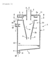
- Figure 1 is a vertical cross-sectional view showing an embodiment of the vapor-liquid separator of the present invention.
- Figure 2 is a vertical cross-sectional view showing another embodiment of the vapor-liquid separator of the present invention.
- Figure 3 is a vertical cross-sectional view showing another embodiment of the vapor-liquid separator of the present invention.
- Figure 4 is a vertical cross-sectional view of the vapor-liquid separator in accordance with the present Example.
- Figure 5 is a cross-sectional view of the II-II cross section in Figure 4.
- Figure 6 is a vertical cross-sectional view showing another embodiment of the vapor-liquid separator of the present invention.
- Figure 7 is a vertical cross-sectional view showing another embodiment of the vapor-liquid separator of the present invention.
- Figure 8 is a vertical cross-sectional view showing another embodiment of the vapor-liquid separator of the present invention.
- 1, 1', 21 and 21'; vapor-liquid separator, 2; separator main body, 3; introduction pipe, 4; oil discharging pipe, 5; gas exhausting pipe, 7; housing, 7'; storage tank, 9; stored-oil discharging pipe, 10; intake pipe, 11 and 11'; communication pipe, 13; baffling part, 13a; first baffling part, 13b; second baffling part, 18; communication pipe, 20; partition wall.
- The vapor-liquid separator of the present invention is an apparatus for separating the vapor-liquid mixed fluid into a gas and a liquid, and comprises a separator main body, an introducing part, a liquid discharging part, a gas exhausting part, a storing part, a stored-liquid discharging part and a communicating part (refer to Fig.1). This vapor-liquid separator may further comprise at least one part among an intake part and a baffling part that are to be described.
An intended use and the like for the vapor-liquid separator of the present invention are not particularly limited, however, the vapor-liquid separator is preferably used, for example, for centrifugally separating a blow-by gas of a vehicle engine into a gas and an oil. - The above-mentioned "separator main body" is not particularly limited in its structure, shape, material and the like so far as it is formed in a tubular shape, however, it is generally in cylindrical.
When the vapor-liquid mixed fluid is introduced into the separator main body, the fluid is swirled and centrifugally separated into a gas and a liquid.
The above-mentioned separator main body may comprise, for example, a cylinder portion (2a) and a tapered cylinder portion (2b) connected to one end side of this cylinder portion (2a) (refer to Figs.1-4, 6, 7 and 8). - The above-mentioned "introducing part" is not particularly limited in its structure, shape, material, position and the like so far as it is connected to the separator main body and is capable of introducing a vapor-liquid mixed fluid into the separator main body in the tangential direction.
The above-mentioned introducing part may for example be an introduction pipe (3) which is connected to an upper portion of the separator main body and extends in the tangential direction of a circumference of the cylinder portion (2a) constituting the separator main body (refer to Fig.5), an introduction pipe which is connected to an upper portion of the separator main body and extends in the tangential direction of a circumference of the tapered cylinder portion (2b) constituting the separator main body, and the like. - The above-mentioned "liquid discharging part" is not particularly limited in its structure, shape, material and the like so far as it is connected to a lower portion of the separator main body and is able to discharge the separated liquid.
The above-mentioned liquid discharging part may for example be a liquid discharge pipe (4) connected to the lower portion of the separator main body (refer to Figs.1-4, 6, 7 and 8).
The liquid discharging part may be arranged in such a manner as to be open to a center side of a storing part mentioned below. Accordingly , it is possible to inhibit a liquid surface of the liquid stored in the storing part from being inclined, and inhibit the liquid from flowing backward to the liquid discharging part, at a time when the vehicle travels on a slope. - The above-mentioned "gas exhausting part" is not particularly limited in its structure, shape, material and the like so far as it is connected to the separator main body and is able to exhaust the separated gas.
The above-mentioned gas exhausting part may for example be a gas exhausting pipe (5) that extends in the axial direction in the separator main body (refer to Figs.1-4, 6, 7 and 8). - The above-mentioned "storing part" is not particularly limited in its structure, shape, material and the like so far as it is able to store the liquid which is discharged passing through the liquid discharging part.
Examples of the above-mentioned storing part include [1] an embodiment of a housing (7) which covers the separator main body and stores the liquid in a bottom portion of the housing (7) (refer to Figs.1-4 and 6), [2] an embodiment of a storage tank (7') which is connected to the liquid discharging part of the separator main body (refer to Figs.7 and 8), and the like.
The housing in accordance with the embodiment [1] may for example be a head cover constituting the vehicle engine.
In the case of the embodiment [2] mentioned above, the liquid discharging part may for example be a liquid discharging pipe that extends from a wall of the storing part to at least an interior of the storing part. - The above-mentioned "stored-liquid discharging part" is not particularly limited in its structure, shape, material and the like so far as it is provided in a lower portion of the storing part mentioned above and is able to discharge the stored liquid.
The above-mentioned stored-liquid discharging part may for example be a stored-liquid discharging pipe (9) that is provided in a lower portion of the storing part mentioned above (refer to Figs.1-4, 6, 7 and 8).
The above-mentioned stored-liquid discharging part may be arranged, for example, in a leading end side of a tapered portion or an inclined portion of a bottom wall of the storing part. Accordingly, it is possible to further improve the dischargeability of the stored liquid.
An opening area (a) of the stored-liquid discharging part mentioned above may be set, for example, to a value smaller than an opening area (b) of the liquid discharging part mentioned above (refer to Figs.1-4, 6, 7 and 8). - The above-mentioned "communicating part" is not particularly limited in its structure, shape, material, position and the like so far as it is be able to communicate the storing part mentioned above with an upstream side of a vapor-liquid separation region of the separator main body and/or the introducing part.
In the case where the storing part mentioned above is the housing (7), the communicating part may for example be communication pipes (11) and (11') which are provided in an upstream side of a vapor-liquid separation region of the separator main body and/or the introducing part and are open to an interior of the housing (7) (refer to Figs.1-4 and 6). This communication pipe (11) may be one that extends in the tangential direction of a circumference of the cylinder portion (2a) constituting the separator main body (refer to Fig.5). In addition, the communication pipe (11) may be one that is connected to an upper portion of the separator main body and extends in the tangential direction of a circumference of the tapered cylinder portion (2b) constituting the separator main body. The above-mentioned communicating part may be disposed at an upstream side of a vapor-liquid separation region of the separator main body and at the introducing part thereof.
In the above case, a spiral plate (17) may be provided in the housing (7) for applying a swirling force to the vapor-liquid mixed fluid that flows toward the upstream side of the vapor-liquid separation region of the separator main body and/or the introducing part (refer to Fig.6). For example, the spiral plate (17) may be fixed to an inner wall of the housing (7) or to an outer wall of the separator main body (2). - Additionally, in the case where the storing part mentioned above is the storage tank (7'), the communicating part mentioned above may for example be a communication pipe (18) communicating the storage tank with the upstream side of the vapor-liquid separation region of the separator main body and/or the introducing part (refer to Figs.7 and 8). The communication pipe (18) may be formed in a spiral shape. Accordingly, it is possible to centrifugally separate the vapor-liquid mixed fluid in the communication pipe (18).
- The above-mentioned "intake part" is not particularly limited in its structure, shape, material and the like so far as it is arranged in the upper portion of the storing part mentioned above and sucks a vapor-liquid mixed fluid which is outside of the storing part.
The above-mentioned intake part may for example be an intake pipe (10) provided in an upper portion of the storing part mentioned above in the case where the storing part is the housing (7). This intake pipe (10) may be formed in such a manner as to extend from a wall of the storing part to at least an interior of the storing part.
Further, in the case where the storing part is the storage tank (7') as shown in Figs.7 and 8, the intake part may be an intake pipe (10) that is formed on an upper wall of the storage portion so as to be open in the vertical direction. This intake pipe (10) may be arranged, for example, near the liquid discharging part which is open to a center side of the storing part (refer to Fig.7). Accordingly, it is possible to inhibit the liquid surface of the liquid stored in the storing part from being inclined at a time when the vehicle travels on a slope, and inhibit the liquid from flowing backward to the intake part.
Moreover, the above-mentioned intake part may be formed on a peripheral wall of the storing part shown in Figs.7 and 8, while being open in the transverse direction.
An opening area (c) of the intake part mentioned above may be set, for example, to a value smaller than an opening area (d) of the introducing part mentioned above (refer to Figs.2, 4, 6, 7 and 8). - The above-mentioned "baffling part" is not particularly limited in its structure, shape, material and the like so far as it is provided in the storing part mentioned above and inhibits the stored liquid in the storing part from flowing backward to the liquid discharging part.
The above-mentioned baffling part may be fixed to an inner wall of the storing part mentioned above or to the separator main body mentioned above.
Examples of the shape of the baffling part include a flat plate shape, a curved plate shape, a lump shape, an irregular shape and the like. - The above-mentioned baffling part may comprise a first baffling part (13a) facing to the opening of the liquid discharging part mentioned above (refer to Figs.3, 4, 6 and 7). The first baffling part (13a) may have an area larger than an opening area of the liquid discharging part.
- Examples of the above-mentioned baffling part include [1] an embodiment wherein the first baffling part (13a) and a second baffling part (13b) that is provided around the first baffling part (13a) are provided, and a space in the storing part is divided vertically into a space (S1) on the liquid discharging part side and a space (S2) on the stored-liquid discharging part side by the first baffling part (13a) and the second baffling part (13b) (refer to Figs.3, 4, 6 and 7), [2] an embodiment having a partition wall (20) dividing a space in the storing part laterally into a space (S1) on the liquid discharging part side and a space (S2) on the stored-liquid discharging part side (refer to Fig.8), and the like.
In the embodiment [1] mentioned above, at least one baffling part of the first baffling part (13a) and the second baffling part (13b) may have a tapered surface (14) inclining relative to the horizontal face (refer to Figs.3, 4, 6 and 7). This tapered surface leads to a smooth guidance of a liquid passed through the liquid discharging part of the separator main body to the bottom side of the storing part. - The present invention will be described in detail hereinafter using Example with some drawings.
In the present Example given here, a vapor-liquid separator separating centrifugally a blow-by gas of a vehicle engine into a gas and an oil is exemplified as the "vapor-liquid separator" of the present invention. - A vapor-liquid separator (1) in accordance with the present Example provides an approximately cylindrical separator main body (2), as shown in Figs.4 and 5. This separator main body (2) has a cylinder portion (2a) and a tapered cylinder portion (2b) connected to a lower end side of this cylinder portion (2a). On a peripheral wall of the cylinder portion (2a), an introduction pipe (3) (exemplified as the "introducing part" of the present invention) that extends in the tangential direction of a circumference of the cylinder portion (2a) constituting the separator main body (2) is provided as shown in Fig.5. In addition, on a peripheral wall of the cylinder portion (2a), a communication pipe (11) (exemplified as the "communicating part" of the present invention) that extends in the tangential direction of a circumference of the cylinder portion (2a) constituting the separator main body (2) is provided being in parallel to the introduction pipe (3). This communication pipe (11) is open to an interior of a housing mentioned below. Further, on a lower end side of the tapered cylinder portion (2b), an oil discharging pipe (4) (exemplified as the "liquid discharging part" of the present invention) is provided being open to the center of the housing mentioned below. Moreover a gas exhausting pipe (5) (exemplified as the "gas exhausting part" of the present invention) that communicates the interior of the separator main body (2) with the exterior and extends in the vertical direction (a direction of a swirling axis) in the separator main body (2) is provided at the center of an upper wall of the separator main body (2).
- The above-mentioned vapor-liquid separator (1) has an approximately cylindrical housing (7) (exemplified as the "storing part" of the present invention) covering the separator main body (2) wholly. A bottom wall of the housing (7) is provided with a stored-oil discharging pipe (9) (exemplified as the "stored-liquid discharging part" of the present invention) in a leading end side of the tapered portion (8). An opening area (a) of the stored-oil discharging pipe (9) is set to a value smaller than an opening area (b) of the oil discharging pipe (4) mentioned above.
- On an upper portion of a peripheral wall of the housing (7), an intake pipe (10) (exemplified as the "intake part" of the present invention) that extends from the wall to inside and outside of the housing (7) is provided. An opening area (c) of the intake pipe (10) is set to a value smaller than an opening area (d) of the introduction pipe (3) mentioned above.
- In the housing (7) mentioned above, there is provided a baffling part (13) inhibiting the stored oil from flowing backward into the separator main body (2) through the oil discharging pipe (4). The baffling part (13) consists of a first baffling part (13a) in umbrella-shaped and a second baffling part (13b) in tapered cylindrical. The first baffling part (13a) is arranged while facing to an opening of the oil discharging pipe (4). Additionally, the second baffling part (13b) is fixed to an outside of the first baffling part (13a) via a support rib (not shown) and the like. An outer circumferential side of the second baffling part (13b) is fixed to an inner wall of the housing (7). A tapered surface (14) inclining relative to the horizontal face is formed on upper surfaces of the first baffling part (13a) and the second baffling part (13b). A space in the housing (7) is divided vertically into a space (S1) on the oil discharging pipe (4) side and a space (S2) on the stored-oil discharging pipe (9) side by the first baffling part (13a) and second baffling part (13b). A communication port (15) that communicates both the spaces (S1) and (S2) is provided between the first baffling part (13a) and the second baffling part (13b).
- In the following, a description will be given of a function of the above-mentioned vapor-liquid separator (1).
When a blow-by gas leaked from a combustion chamber of a vehicle engine is introduced into the separator main body (2) via the introduction pipe (3) in the tangential direction, the introduced blow-by gas forms a swirling flow and are centrifugally separated into a gas and an oil (oil mist). The separated gas is exhaustd outside via the gas exhausting pipe (5). On the other hand, the separated oil flows toward a lower side of the separator main body (2) along an inner peripheral surface on the basis of its own weight and is temporarily stored in a bottom portion of the housing (7) through the oil discharging pipe (4). After that, if a suction force of the blow-by gas flowing backward from the stored-oil discharging pipe (9) becomes smaller than a weight of the stored oil at a time of an idling or the like, the stored oil is discharged outside via the stored-oil discharging pipe (9). - In the case of sucking a blow-by gas, the blow-by gas is sucked into the housing (7) via the intake pipe (10) and the suction force of the blow-by gas flowing backward from the stored-oil discharging pipe (9) of the housing (7) is weakened. In addition, the blow-by gas flowing backward from the stored-oil discharging pipe (9) into the housing (7) is flowed into an upstream side of the vapor-liquid separation region of the separator main body (2) via the communication pipe (11) so as to be separated into a gas and an oil in the separator main body (2). Further, it is possible to inhibit the oil stored in the housing (7) from flowing backward to the oil discharge pipe (4) by the first baffling part (13a) and the second baffling part (13b).
It is noted that, a suction force (negative pressure) (Q) applying to the gas exhausting pipe (5) is obtained by a total of a suction force (Q1) of the introduction pipe (3), a suction force (Q2) of the intake pipe (10) and a suction force (Q3) of the stored-oil discharging pipe (9), at a time of sucking the blow-by gas. - Since the vapor-liquid separator (1) of the present Example has the housing (7), the separated oil obtained by the separator main body (2) is discharged while storing and the dischargeability of the oil at the stored-oil discharging part (9) of the housing (7) is improved. In addition, since the stored-oil discharging pipe (9) of the housing (7) is not provided with the conventional valve mechanism which comes to the closed state during the operation, it is possible to discharge the stored oil in the housing (7) even under operation and to lead to a downsizing of the housing (7) and a simplification of the structure.
- Further, since the structure is made such as to suck the blow-by gas into the housing (7) by means of the intake pipe (10), it is possible to suppress a reversed flow of the blow-by gas from the stored-oil discharging pipe (9) and to inhibit the stored oil from splashing due to the reversed flow of the blow-by gas. As a result, it is possible to inhibit the stored oil from flowing backward to the oil discharging pipe (4) of the separator main body (2) and to improve the oil dischargeability at the oil discharging pipe (4) of the separator main body (2).
- Additionally, since the opening area (c) of the intake pipe (10) is set to the smaller value than the opening area (d) of the introduction pipe (3), it is possible to suppress the intake amount of the blow-by gas from the intake pipe (10) to a minimum level. Therefore, it is possible to introduce most of the blow-by gas into the separator main body (2) via the introduction pipe (3) and to separate into a gas and an oil.
Further, since the opening area (a) of the stored-oil discharging pipe (9) is set to the smaller value than the opening area (b) of the oil discharging pipe (4), it is possible to more securely suppress the reversed flow of the blow-by gas to the stored-oil discharging pipe (9) and to further improve the oil dischargeability at the oil discharging pipe (4). - Furthermore, since the structure is made such as to flow the reversed blow-by gas into the housing (7) via the stored-oil discharging pipe (9) into the separator main body (2) by means of the communication pipe (11) and separate into a gas and an oil, it is possible to inhibit the stored oil from splashing due to the reversed blow-by gas and to inhibit the reversed flow into the oil discharging pipe (4). As a result, it is possible to more securely suppress the backflow of the stored oil into the oil discharging pipe (4) of the separator main body (2) and to further improve the oil dischargeability at the oil discharging pipe (4) of the separator main body (2).
- Further, since the first baffling part (13a) facing to the opening of the oil discharging pipe (4) and the second baffling part (13b) are provided in the housing (7) to divide the internal space of the housing (7) into two spaces (S1) and (S2), it is possible to more securely suppress the backflow of the stored oil into the oil discharging pipe (4) of the separator main body (2) and to further improve the oil dischargeability at the oil discharging pipe (4) of the separator main body (2).
Moreover, since the first baffling part (13a) and the second baffling part (13b) have the tapered surface (14) inclined relative to the horizontal face, it is possible to smoothly guide the oil discharged via the oil discharging pipe (4) of the separator main body (2) to the bottom portion of the housing (7) by means of the tapered surfaces (14). - It is noted that the present invention is not limited to the Example mentioned above and may employ embodiments which are variously modified within the scope of the present invention in correspondence to a purpose and an intended use.
For example, the communication pipe (11) is provided in the cylinder portion (2a) of the separator main body (2) in the Example mentioned above (refer to Fig.4), however, the structure is not limited to this embodiment and the communication pipe (11) may be provided in the upper portion of the tapered cylinder portion (2b) of the separator main body (2), or a communication pipe (11') may be provided in the middle of the introduction pipe (3), as shown in Fig.6.
In addition, the structure may be made such that an inner wall of the housing (7) in the Example mentioned above is provided with a spiral plate (17) for applying a swirling force to the blow-by gas flowing in the housing (7) shown in Fig.6. Accordingly, it is possible to separate the blow-by gas into a gas and an oil by the spiral plate (17) even in the housing (7). - Further, the housing (7) is exemplified as the storing part in the Example mentioned above, however, the structure is not limited to this embodiment and a storage tank (7') to which the oil discharging pipe (4) of the separator main body (2) is connected, as shown in Figs.7 and 8. In this case, there may be provided with a communication pipe (18) that communicates the cylinder portion (2a) of the separator main body (2) (or the upper portion of the tapered cylinder portion (2b)) and the storage tank (7'), or may be provided with a communication pipe (not shown) that communicates the introduction pipe (3) with the storage tank (7'). Even in this case, the baffling part (13) may be provided in the storage tank (7').
Moreover, according to the Example mentioned above, the baffling parts (13) consisting of the first baffling part (13a) and the second baffling part (13b) are provided to divide the internal space of the storing part vertically into two spaces (S1) and (S2) shown in Fig.4, however, the structure is not limited to this embodiment and a partition wall (20) may be provided for dividing the internal space of the storing part laterally into two spaces (S1) and (S2) as shown in Fig.8. - Further, there is exemplified the aspect that one intake pipe (10) is provided in the storing part according to the Example mentioned above, however, the structure is not limited to this embodiment and a plurality of intake pipes may be provided in the storing part. In this case, it is preferable that the total of the opening areas of a plurality of intake pipes is set to the smaller value than the opening area of the introduction pipe.
- The present invention is widely utilized as a technique of centrifugally separating the vapor-liquid mixed fluid into a gas and a liquid. In particular, the present invention is preferably utilized as a technique of centrifugally separating a blow-by gas of a vehicle engine into a gas and an oil.
The object of the present invention is to provide a vapor-liquid separator capable of improving a dischargeability of a separated liquid and of suppressing a reversed flow. The present vapor-liquid separator (1) comprises a cylindrical separator main body (2), an introducing part (3) for introducing the vapor-liquid mixed fluid into the separator main body (2) in the tangential direction, a liquid discharging part (4) for discharging a separated liquid, a gas exhausting part (5) for exhausting the separated gas, a storing part (7) for storing a liquid passed through the liquid discharging part (4), a stored-liquid discharging part (9) provided in the storing part (7) to discharge a stored liquid and a communicating part (11) for communicating the storing part (7) with an upstream side of a vapor-liquid separation region of the separator main body (2) and/or the introducing part (3).
Claims (9)
- A vapor-liquid separator which comprises a cylindrical separator main body, an introducing part which is provided on said separator main body and is for introducing said vapor-liquid mixed fluid into said separator main body in the tangential direction, a liquid discharging part which is provided on said separator main body and is for discharging a separated liquid, and a gas exhausting part which is provided on said separator main body and is for exhausting a separated gas, said vapor-liquid separator characterized by comprising a storing part for storing a liquid which is discharged from said liquid discharging part, a stored-liquid discharging part which is provided in said storing part and is for discharging a stored liquid, and a communicating part for communicating said storing part with an upstream side of a vapor-liquid separation region of said separator main body and/or said introducing part.
- The vapor-liquid separator according to Claim 1,
wherein said storing part is a housing for covering said separator main body, and
wherein said communicating part is a communication pipe which is provided on an upstream side of a vapor-liquid separation region of said separator main body and/or on said introducing part and is communicating with an interior of said housing. - The vapor-liquid separator according to Claim 2, further comprising a spiral plate applying a swirling force to a vapor-liquid mixed fluid flowing toward an upstream side of a vapor-liquid separation region of said separator main body and/or said introducing part in said housing.
- The vapor-liquid separator according to Claim 1,
wherein said storing part is a storage tank to which said liquid discharging part of said separator main body is connected, and
wherein said communicating part is a communication pipe for communicating said storage tank with an upstream side of a vapor-liquid separation region of said separator main body and/or said introducing part. - The vapor-liquid separator according to any one of Claims 1 to 4, further comprising an intake part which is provided on said storing part and is for suctioning a vapor-liquid mixed fluid existing outside of said storing part.
- The vapor-liquid separator according to Claim 5,
wherein an opening area of said intake part is smaller than an opening area of said introducing part. - The vapor-liquid separator according to any one of Claims 1 to 6, further comprising a baffling part which is provided in said storing part and is for inhibiting a liquid stored in said storing part from flowing backward to said liquid discharging part.
- The vapor-liquid separator according to Claim 7,
wherein said baffling part has a tapered surface inclined relative to the horizontal face. - The vapor-liquid separator according to any one of Claims 1 to 8,
wherein said vapor-liquid mixed fluid is a blow-by gas.
Applications Claiming Priority (1)
| Application Number | Priority Date | Filing Date | Title |
|---|---|---|---|
| JP2006212639A JP4626586B2 (en) | 2006-08-03 | 2006-08-03 | Gas-liquid separator |
Publications (2)
| Publication Number | Publication Date |
|---|---|
| EP1887192A1 true EP1887192A1 (en) | 2008-02-13 |
| EP1887192B1 EP1887192B1 (en) | 2009-02-18 |
Family
ID=38375700
Family Applications (1)
| Application Number | Title | Priority Date | Filing Date |
|---|---|---|---|
| EP07111153A Not-in-force EP1887192B1 (en) | 2006-08-03 | 2007-06-27 | Vapor-liquid separator |
Country Status (4)
| Country | Link |
|---|---|
| US (1) | US7401599B2 (en) |
| EP (1) | EP1887192B1 (en) |
| JP (1) | JP4626586B2 (en) |
| DE (1) | DE602007000564D1 (en) |
Cited By (1)
| Publication number | Priority date | Publication date | Assignee | Title |
|---|---|---|---|---|
| EP4375559A1 (en) * | 2022-11-28 | 2024-05-29 | Pratt & Whitney Canada Corp. | Static de-aerator and lubricant system |
Families Citing this family (18)
| Publication number | Priority date | Publication date | Assignee | Title |
|---|---|---|---|---|
| JP4510108B2 (en) * | 2008-03-13 | 2010-07-21 | 小島プレス工業株式会社 | Oil separator for blow-by gas |
| DE102008017919A1 (en) * | 2008-04-08 | 2009-10-15 | Mann + Hummel Gmbh | Separator for crankcase ventilation of an internal combustion engine |
| DE102009012400A1 (en) * | 2009-03-10 | 2010-09-23 | Thyssenkrupp Presta Teccenter Ag | Hollow body with integrated oil separator |
| JP5795977B2 (en) | 2012-03-14 | 2015-10-14 | 株式会社荏原製作所 | Polishing equipment |
| US9435304B2 (en) * | 2012-08-27 | 2016-09-06 | Robert Bosch Gmbh | Diesel fuel pump module |
| US9366206B2 (en) * | 2012-12-17 | 2016-06-14 | Ford Global Technologies, Llc | Fuel-air separator and pulse dampener |
| JP5964740B2 (en) | 2012-12-21 | 2016-08-03 | 株式会社荏原製作所 | Polishing equipment |
| US9732707B1 (en) * | 2013-12-09 | 2017-08-15 | High Output Technology, LLC | Vent for engine crankcases |
| JP6248804B2 (en) * | 2014-05-20 | 2017-12-20 | アイシン精機株式会社 | Oil separator |
| JP6401591B2 (en) * | 2014-12-02 | 2018-10-10 | 株式会社日立産機システム | Multistage compressor cooler and multistage compressor provided with the same |
| JP6631489B2 (en) * | 2016-04-08 | 2020-01-15 | 株式会社デンソー | Heat exchanger |
| KR101971778B1 (en) * | 2017-05-08 | 2019-04-23 | 엘지전자 주식회사 | cyclone for air cleaning and filtering module having the same |
| US11058979B2 (en) * | 2018-01-19 | 2021-07-13 | Ge Aviation Systems Llc | Air-oil separator |
| CN111336040B (en) * | 2020-03-18 | 2021-03-09 | 东风汽车集团有限公司 | Fuel steam liquefaction recovery device and fuel evaporation and discharge system thereof |
| CN112302614B (en) * | 2020-11-02 | 2022-06-07 | 青岛理工大学 | Compact L-shaped column-cone combined tube type three-stage axial flow degassing device |
| CN112892001B (en) * | 2021-01-13 | 2022-05-17 | 青岛理工大学 | Microbubble axial flow and rotational flow double-field three-stage pipe type T-shaped degassing device |
| BE1029751B1 (en) * | 2021-09-14 | 2023-04-11 | Safran Aero Boosters | OIL DEAERATOR DEVICE WITH TANK PROVIDED WITH A STABILIZATION WALL |
| US20240017228A1 (en) * | 2022-07-14 | 2024-01-18 | Uop Llc | Process and apparatus for separating catalyst from product gas |
Citations (6)
| Publication number | Priority date | Publication date | Assignee | Title |
|---|---|---|---|---|
| JPH05231121A (en) | 1992-02-19 | 1993-09-07 | Toyota Autom Loom Works Ltd | Oil removing device for blow-by gas |
| US5450835A (en) * | 1994-11-15 | 1995-09-19 | Cummins Engine Company, Inc. | Oil separator for reducing oil losses from crankcase ventilation |
| JP2003049625A (en) | 2001-08-06 | 2003-02-21 | Honda Motor Co Ltd | Engine gas-liquid separator |
| JP2003120250A (en) | 2001-10-19 | 2003-04-23 | Honda Motor Co Ltd | Breather device |
| JP2005146972A (en) | 2003-11-14 | 2005-06-09 | Toyota Motor Corp | Breather equipment |
| EP1669119A1 (en) * | 2004-11-22 | 2006-06-14 | Eaton Corporation | Integrated three-phase cyclonic fluid seperator and reservoir venting device |
Family Cites Families (16)
| Publication number | Priority date | Publication date | Assignee | Title |
|---|---|---|---|---|
| US4184858A (en) * | 1975-02-28 | 1980-01-22 | Walker Robert A | Engine emission control device |
| US4269607A (en) * | 1977-11-07 | 1981-05-26 | Walker Robert A | Air-oil separator and method of separation |
| DE3914759A1 (en) * | 1989-05-05 | 1990-11-08 | Mann & Hummel Filter | FILLING OPENING FOR FILLING LUBRICANT OIL INTO AN INTERNAL COMBUSTION ENGINE |
| JPH0332113U (en) * | 1989-08-09 | 1991-03-28 | ||
| US5243950A (en) * | 1992-12-07 | 1993-09-14 | Gekko International, L.C. | Apparatus for the treatment of gases in a positive crankcase ventilation system |
| DE4221885C2 (en) * | 1992-07-03 | 1996-03-28 | Freudenberg Carl Fa | Liquid separator |
| US5587068A (en) * | 1994-11-15 | 1996-12-24 | United Technologies Corporation | Multi-attitude deaerator for oil tank |
| JP3049269B2 (en) * | 1995-05-26 | 2000-06-05 | 小島プレス工業株式会社 | Oil trapper for internal combustion engine |
| DE19912271A1 (en) * | 1999-03-18 | 2000-09-28 | Hengst Walter Gmbh & Co Kg | Oil separator for de-oiling crankcase ventilation gases of an internal combustion engine |
| JP2001246216A (en) * | 1999-12-28 | 2001-09-11 | Denso Corp | Gas-liquid separation device |
| JP4558984B2 (en) * | 2001-06-28 | 2010-10-06 | ヤマハ発動機株式会社 | Blow-by gas separator |
| JP3760314B2 (en) | 2001-10-16 | 2006-03-29 | 三和シヤッター工業株式会社 | Architectural shutter device with soundproofing function |
| DE10239408A1 (en) * | 2002-08-28 | 2004-03-11 | Robert Bosch Gmbh | Device for separating liquid from a gas stream |
| DE10325055A1 (en) * | 2003-06-02 | 2004-12-23 | Mann + Hummel Gmbh | Device for switching cyclones |
| GB0414344D0 (en) * | 2004-06-26 | 2004-07-28 | Rolls Royce Plc | Centrifugal gas/liquid separators |
| JP4622868B2 (en) * | 2006-01-16 | 2011-02-02 | トヨタ紡織株式会社 | Bubble separator |
-
2006
- 2006-08-03 JP JP2006212639A patent/JP4626586B2/en not_active Expired - Fee Related
-
2007
- 2007-06-14 US US11/763,080 patent/US7401599B2/en not_active Expired - Fee Related
- 2007-06-27 EP EP07111153A patent/EP1887192B1/en not_active Not-in-force
- 2007-06-27 DE DE602007000564T patent/DE602007000564D1/en active Active
Patent Citations (6)
| Publication number | Priority date | Publication date | Assignee | Title |
|---|---|---|---|---|
| JPH05231121A (en) | 1992-02-19 | 1993-09-07 | Toyota Autom Loom Works Ltd | Oil removing device for blow-by gas |
| US5450835A (en) * | 1994-11-15 | 1995-09-19 | Cummins Engine Company, Inc. | Oil separator for reducing oil losses from crankcase ventilation |
| JP2003049625A (en) | 2001-08-06 | 2003-02-21 | Honda Motor Co Ltd | Engine gas-liquid separator |
| JP2003120250A (en) | 2001-10-19 | 2003-04-23 | Honda Motor Co Ltd | Breather device |
| JP2005146972A (en) | 2003-11-14 | 2005-06-09 | Toyota Motor Corp | Breather equipment |
| EP1669119A1 (en) * | 2004-11-22 | 2006-06-14 | Eaton Corporation | Integrated three-phase cyclonic fluid seperator and reservoir venting device |
Cited By (2)
| Publication number | Priority date | Publication date | Assignee | Title |
|---|---|---|---|---|
| EP4375559A1 (en) * | 2022-11-28 | 2024-05-29 | Pratt & Whitney Canada Corp. | Static de-aerator and lubricant system |
| EP4628182A3 (en) * | 2022-11-28 | 2026-01-07 | Pratt & Whitney Canada Corp. | Static de-aerator and lubricant system |
Also Published As
| Publication number | Publication date |
|---|---|
| DE602007000564D1 (en) | 2009-04-02 |
| JP4626586B2 (en) | 2011-02-09 |
| US20080029071A1 (en) | 2008-02-07 |
| JP2008038712A (en) | 2008-02-21 |
| EP1887192B1 (en) | 2009-02-18 |
| US7401599B2 (en) | 2008-07-22 |
Similar Documents
| Publication | Publication Date | Title |
|---|---|---|
| US7401599B2 (en) | Vapor-liquid separator | |
| US7871461B2 (en) | Bubble separator | |
| US7655078B2 (en) | Bubble separator | |
| CN101918103A (en) | Separator with transfer pipe discharge | |
| CN109236658B (en) | An oil and gas separator | |
| JP4626587B2 (en) | Gas-liquid separator | |
| US7530430B2 (en) | Pressure lubrication for inverted flight | |
| JP4352228B2 (en) | Breather equipment | |
| JP4635981B2 (en) | Gas-liquid separator | |
| JP6010011B2 (en) | Breather system for internal combustion engines | |
| EP1030037B1 (en) | Breather system | |
| JP4535137B2 (en) | Crankcase for internal combustion engine | |
| EP4023861B1 (en) | Air-oil separator drain valve and related method of use | |
| JP5034357B2 (en) | Gas-liquid separator | |
| JP4442813B2 (en) | Oil separation device for blow-by gas in internal combustion engines | |
| CN106979047B (en) | Oil sump with the oil scupper for being exclusively used in positive crankcase ventilation (PCV) | |
| JP7666302B2 (en) | Gas-liquid separator | |
| JPH1018831A (en) | Oil trapper for internal combustion engine | |
| JP2006063803A (en) | Engine blow-by gas reduction device | |
| CN201884094U (en) | Engine air interchanging device | |
| JP2007120398A (en) | Air bubble separator | |
| JPH10115293A (en) | Oil separator for oil-cooled compressor | |
| JP4119698B2 (en) | Oil-cooled compressor receiver tank | |
| JP2009257152A (en) | Fuel supply device | |
| KR20240053783A (en) | Oil separation device of intake manifold for gas-liquid separation |
Legal Events
| Date | Code | Title | Description |
|---|---|---|---|
| PUAI | Public reference made under article 153(3) epc to a published international application that has entered the european phase |
Free format text: ORIGINAL CODE: 0009012 |
|
| 17P | Request for examination filed |
Effective date: 20070627 |
|
| AK | Designated contracting states |
Kind code of ref document: A1 Designated state(s): AT BE BG CH CY CZ DE DK EE ES FI FR GB GR HU IE IS IT LI LT LU LV MC MT NL PL PT RO SE SI SK TR |
|
| AX | Request for extension of the european patent |
Extension state: AL BA HR MK YU |
|
| GRAP | Despatch of communication of intention to grant a patent |
Free format text: ORIGINAL CODE: EPIDOSNIGR1 |
|
| AKX | Designation fees paid |
Designated state(s): DE FR GB |
|
| GRAS | Grant fee paid |
Free format text: ORIGINAL CODE: EPIDOSNIGR3 |
|
| GRAA | (expected) grant |
Free format text: ORIGINAL CODE: 0009210 |
|
| AK | Designated contracting states |
Kind code of ref document: B1 Designated state(s): DE FR GB |
|
| REG | Reference to a national code |
Ref country code: GB Ref legal event code: FG4D |
|
| REF | Corresponds to: |
Ref document number: 602007000564 Country of ref document: DE Date of ref document: 20090402 Kind code of ref document: P |
|
| PLBE | No opposition filed within time limit |
Free format text: ORIGINAL CODE: 0009261 |
|
| STAA | Information on the status of an ep patent application or granted ep patent |
Free format text: STATUS: NO OPPOSITION FILED WITHIN TIME LIMIT |
|
| 26N | No opposition filed |
Effective date: 20091119 |
|
| REG | Reference to a national code |
Ref country code: FR Ref legal event code: ST Effective date: 20100226 |
|
| PG25 | Lapsed in a contracting state [announced via postgrant information from national office to epo] |
Ref country code: FR Free format text: LAPSE BECAUSE OF NON-PAYMENT OF DUE FEES Effective date: 20090630 |
|
| GBPC | Gb: european patent ceased through non-payment of renewal fee |
Effective date: 20110627 |
|
| PG25 | Lapsed in a contracting state [announced via postgrant information from national office to epo] |
Ref country code: GB Free format text: LAPSE BECAUSE OF NON-PAYMENT OF DUE FEES Effective date: 20110627 |
|
| PGFP | Annual fee paid to national office [announced via postgrant information from national office to epo] |
Ref country code: DE Payment date: 20120620 Year of fee payment: 6 |
|
| REG | Reference to a national code |
Ref country code: DE Ref legal event code: R119 Ref document number: 602007000564 Country of ref document: DE Effective date: 20140101 |
|
| PG25 | Lapsed in a contracting state [announced via postgrant information from national office to epo] |
Ref country code: DE Free format text: LAPSE BECAUSE OF NON-PAYMENT OF DUE FEES Effective date: 20140101 |