EP1886751A2 - Quick acting clamping device, closing unit and system for quick clamping - Google Patents
Quick acting clamping device, closing unit and system for quick clamping Download PDFInfo
- Publication number
- EP1886751A2 EP1886751A2 EP07015177A EP07015177A EP1886751A2 EP 1886751 A2 EP1886751 A2 EP 1886751A2 EP 07015177 A EP07015177 A EP 07015177A EP 07015177 A EP07015177 A EP 07015177A EP 1886751 A2 EP1886751 A2 EP 1886751A2
- Authority
- EP
- European Patent Office
- Prior art keywords
- clamping
- quick
- unit
- cylinder
- pressure
- Prior art date
- Legal status (The legal status is an assumption and is not a legal conclusion. Google has not performed a legal analysis and makes no representation as to the accuracy of the status listed.)
- Granted
Links
- 238000007789 sealing Methods 0.000 claims description 20
- 230000004913 activation Effects 0.000 claims description 16
- 238000003780 insertion Methods 0.000 claims description 14
- 230000037431 insertion Effects 0.000 claims description 14
- 230000000712 assembly Effects 0.000 claims description 5
- 238000000429 assembly Methods 0.000 claims description 5
- 230000000284 resting effect Effects 0.000 claims description 2
- 238000006073 displacement reaction Methods 0.000 description 3
- 239000012530 fluid Substances 0.000 description 2
- 238000012544 monitoring process Methods 0.000 description 1
- ORQBXQOJMQIAOY-UHFFFAOYSA-N nobelium Chemical compound [No] ORQBXQOJMQIAOY-UHFFFAOYSA-N 0.000 description 1
- 230000002093 peripheral effect Effects 0.000 description 1
Images

Classifications
-
- B—PERFORMING OPERATIONS; TRANSPORTING
- B23—MACHINE TOOLS; METAL-WORKING NOT OTHERWISE PROVIDED FOR
- B23B—TURNING; BORING
- B23B31/00—Chucks; Expansion mandrels; Adaptations thereof for remote control
- B23B31/001—Protection against entering of chips or dust
-
- B—PERFORMING OPERATIONS; TRANSPORTING
- B23—MACHINE TOOLS; METAL-WORKING NOT OTHERWISE PROVIDED FOR
- B23B—TURNING; BORING
- B23B31/00—Chucks; Expansion mandrels; Adaptations thereof for remote control
- B23B31/02—Chucks
- B23B31/10—Chucks characterised by the retaining or gripping devices or their immediate operating means
- B23B31/12—Chucks with simultaneously-acting jaws, whether or not also individually adjustable
- B23B31/16—Chucks with simultaneously-acting jaws, whether or not also individually adjustable moving radially
- B23B31/16233—Jaws movement actuated by oblique surfaces of a coaxial control rod
- B23B31/16254—Jaws movement actuated by oblique surfaces of a coaxial control rod using fluid-pressure means to actuate the gripping means
-
- B—PERFORMING OPERATIONS; TRANSPORTING
- B23—MACHINE TOOLS; METAL-WORKING NOT OTHERWISE PROVIDED FOR
- B23Q—DETAILS, COMPONENTS, OR ACCESSORIES FOR MACHINE TOOLS, e.g. ARRANGEMENTS FOR COPYING OR CONTROLLING; MACHINE TOOLS IN GENERAL CHARACTERISED BY THE CONSTRUCTION OF PARTICULAR DETAILS OR COMPONENTS; COMBINATIONS OR ASSOCIATIONS OF METAL-WORKING MACHINES, NOT DIRECTED TO A PARTICULAR RESULT
- B23Q1/00—Members which are comprised in the general build-up of a form of machine, particularly relatively large fixed members
- B23Q1/0063—Connecting non-slidable parts of machine tools to each other
- B23Q1/0072—Connecting non-slidable parts of machine tools to each other using a clamping opening for receiving an insertion bolt or nipple
-
- B—PERFORMING OPERATIONS; TRANSPORTING
- B23—MACHINE TOOLS; METAL-WORKING NOT OTHERWISE PROVIDED FOR
- B23B—TURNING; BORING
- B23B2260/00—Details of constructional elements
- B23B2260/126—Seals
-
- Y—GENERAL TAGGING OF NEW TECHNOLOGICAL DEVELOPMENTS; GENERAL TAGGING OF CROSS-SECTIONAL TECHNOLOGIES SPANNING OVER SEVERAL SECTIONS OF THE IPC; TECHNICAL SUBJECTS COVERED BY FORMER USPC CROSS-REFERENCE ART COLLECTIONS [XRACs] AND DIGESTS
- Y10—TECHNICAL SUBJECTS COVERED BY FORMER USPC
- Y10T—TECHNICAL SUBJECTS COVERED BY FORMER US CLASSIFICATION
- Y10T279/00—Chucks or sockets
- Y10T279/12—Chucks or sockets with fluid-pressure actuator
- Y10T279/1274—Radially reciprocating jaws
- Y10T279/1291—Fluid pressure moves jaws via mechanical connection
-
- Y—GENERAL TAGGING OF NEW TECHNOLOGICAL DEVELOPMENTS; GENERAL TAGGING OF CROSS-SECTIONAL TECHNOLOGIES SPANNING OVER SEVERAL SECTIONS OF THE IPC; TECHNICAL SUBJECTS COVERED BY FORMER USPC CROSS-REFERENCE ART COLLECTIONS [XRACs] AND DIGESTS
- Y10—TECHNICAL SUBJECTS COVERED BY FORMER USPC
- Y10T—TECHNICAL SUBJECTS COVERED BY FORMER US CLASSIFICATION
- Y10T279/00—Chucks or sockets
- Y10T279/19—Radially reciprocating jaws
- Y10T279/1973—Wedge actuated
Definitions
- Input called quick-release units are known from the prior art, for example, from DE 103 17 336 A1 or the DE 20 2004 009 283 U1 previously known.
- the piston member is arranged axially movable in a cylinder, wherein when pressure is applied to the pressure chamber, the piston member moves the clamping elements in the unlocking or locking position.
- the clamping elements can be formed, for example, as balls, as pins or as a slider.
- the cylinder element is advantageously arranged axially displaceably on the piston element and is for the radial movement of at least one clamping element with the clamping element directly, in particular via inclined guides, motion coupled.
- the inclined guides can be designed according to a wedge hook gear; an axial movement of the cylinder element results in a radial movement of the at least one, in particular designed as a clamping slide, clamping element due to the oblique arrangement of the mutually cooperating guides.
- the main body has a cylinder space receiving, for displaceable storage of the cylinder element pressurizable cylinder space.
- the cylinder element as such, which is arranged movably in the cylinder space, thereby receives the function of a piston.
- Advantage of such a design is that the cylinder chamber is easily accessible from a pressure line, whereby a secure pressure supply is ensured.
- the sealing element is preferably formed as a sealing bellows, which is arranged on the one hand on the pressure element and on the other hand on a ring-shaped or plate-like, radially outwardly projecting edge of the support member.
- the diameter of the sealing bellows is smaller when the pressure element is in the insertion position than when the pressure element is moved axially into the closed position. Due to the increasing diameter of the sealing element with itself in the closed position moving pressure element, a closure of the clamping receptacle can be achieved.
- the carrier part as such can provide an existing in the carrier part, the support member by cross-axially arranged under spring bias valve body over which at a occurring within the closure unit pressure compressed air from the carrier part, in particular for removing chips and dirt in the clamping fixture, can escape.
- the closure element 40 has an opening 42 towards the interior 44 of the hollow piston element 26.
- a closure unit for closing the tension receptacle 14 may be provided, for example.
- other modules or units for example a surveillance camera or monitoring sensors, can be arranged in the interior 44.
- FIGS. 7-11 show a closure unit 80 for arrangement in the inner space 44 of the clamping unit 10 according to FIGS. 1, 2 and 4-6.
- the closure unit 80 comprises an axially formed on a support member 82 between an insertion position shown in Figures 8 and 9 and a closure position shown in Figures 10 and 11, ring-shaped pressure element 84. Between the pressure element 84 and a radially projecting edge 86th the carrier part 82, a bellows-shaped elastic sealing element 88 is arranged.
- the support member itself can be formed in several parts, as shown in the figures.
- valve body 92 which passes through the carrier part 82 and is arranged axially under the bias of a spring 90 is arranged in the carrier part 82.
- the valve body 92 comprises a radially extending valve plate 94, which covers the top of the support member 82 substantially completely.
- the valve body 92 comprises an axially extending valve rod 96 which extends in the region of the central longitudinal axis 98 and engages through the support member 82 in the axial direction.
Abstract
Description
Die Erfindung betrifft eine Schnellspanneinheit mit einer von einem Grundkörper gebildeten Spannaufnahme, mit wenigstens einem gegenüber dem Grundkörper zwischen einer Entriegelungsstellung und einer Verriegelungsstellung beweglich angeordneten Spannelement, mit einem Zylinder und einem im Zylinder angeordneten, mit dem Zylinder wenigstens einen Druckraum begrenzenden Kolbenelement, wobei bei einer Druckbeaufschlagung des Druckraums mit einem Druckmittel das Spannelement in die Verriegelungslage oder die Entriegelungslage bewegt wird. Die Erfindung betrifft auch eine Verschlusseinheit zum Verschließen der Spannaufnahme einer Schnellspanneinheit sowie ein Schnellspannsystem, umfassend eine Schnellspanneinheit und eine Verschlusseinheit.The invention relates to a quick-release unit having a clamping receptacle formed by a base body, with at least one relative to the main body between an unlocked position and a locking position movably arranged clamping element, arranged with a cylinder and a cylinder disposed in the cylinder with at least one pressure chamber piston element, wherein at a Pressurization of the pressure chamber with a pressure medium, the clamping element in the locking position or the Unlocking position is moved. The invention also relates to a closure unit for closing the tension receptacle of a quick-release unit and a quick-release system, comprising a quick-release unit and a closure unit.
Eingangs genannte Schnellspanneinheiten sind aus dem Stand der Technik beispielsweise aus der
Der vorliegenden Erfindung liegt die Aufgabe zugrunde, eine Schnellspanneinheit vorzuschlagen, die einen vorteilhaften Aufbau aufweist und funktionssicher arbeitet.The present invention has for its object to provide a quick-release unit, which has an advantageous structure and works functionally reliable.
Hierzu wird eine Schnellspanneinheit der eingangs genannten Art vorgeschlagen, die zusätzlich die Merkmale des Anspruchs 1 aufweist. Folglich ist vorgesehen, dass das Kolbenelement als gegenüber dem Grundkörper feststehendes Kolbenelement und der Zylinder als gegenüber dem Grundkörper und dem Kolbenelement bewegliches Zylinderelement ausgebildet ist. Gemäß der Erfindung wird also bei Druckbeaufschlagung des Druckraums mit einem fluidischen Druckmittel, wie insbesondere Druckluft oder Hydraulikflüssigkeit, nicht das Kolbenelement, sondern das Zylinderelement bewegt. Aufgrund des Vorsehens eines feststehenden Kolbenelements können am Kolbenelement Baugruppen oder Einheiten angeordnet und befestigt werden. Der Druckraum kann insbesondere um das Kolbenelement ringartig verlaufend ausgebildet.For this purpose, a quick-release unit of the aforementioned type is proposed, which additionally has the features of claim 1. Consequently, it is provided that the piston element is designed as a respect to the base body fixed piston member and the cylinder as compared to the base body and the piston member movable cylinder member. According to the invention, therefore, when the pressure chamber is pressurized with a fluidic pressure medium, in particular compressed air or hydraulic fluid, not the piston element but the cylinder element is moved. Due to the provision of a fixed piston member assemblies or units can be arranged and fixed on the piston element. The pressure chamber can be designed to extend in an annular manner, in particular around the piston element.
Vorteilhafterweise ist das Kolbenelement als Hohlkolbenelement ausgebildet ist. Aufgrund der Verwendung eines Hohlkolbenelements wird innerhalb des Hohlkolbenelements Bauraum zur Anordnung von Baugruppen oder Einheiten zur Verfügung gestellt. Die Baugruppen oder Einheiten können unmittelbar an der Innenseite des Hohlkolbenelements befestig werden. Das Hohlkolbenelement ist dabei vorzugsweise wenigstes einseitig offen bzw. wenigstes von einer Seite aus zugänglich, um entsprechende Baugruppen oder Einheiten im Hohlkolbenelement unterbringen zu können.Advantageously, the piston element is designed as a hollow piston element. Due to the use of a hollow piston element, space is provided within the hollow piston element for the arrangement of assemblies or units. The modules or units can be fastened directly to the inside of the hollow piston element. The hollow piston element is preferably at least one side open or wenigstes accessible from one side to accommodate corresponding assemblies or units in the hollow piston element can.
Vorzugsweise erstreckt sich die Innenseite des als Hohlkolbenelement ausgebildeten Kolbenelements in axialer Verlängerung der Spannaufnahme zur abschnittsweisen Axialführung eines in die Spannaufnahme eingreifenden Spannbolzens. Das Kolbenelement, bzw. dessen Innseite, übernimmt dabei also eine Führungsfunktion beim Einführen des Spannbolzens in die Spannaufnahme.Preferably, the inside of the piston element designed as a hollow piston element extends in the axial extension of the clamping receptacle for the sectional axial guidance of a clamping bolt engaging in the clamping receptacle. The piston element, or its inner side, thus assumes a guiding function during insertion of the clamping bolt into the clamping receptacle.
Das Zylinderelement ist dabei vorteilhafterweise auf dem Kolbenelement axial verschieblich angeordnet und ist zur radialen Bewegung wenigstens eines Spannelements mit dem Spannelement direkt, insbesondere über Schrägführungen, bewegungsgekoppelt. Die Schrägführungen können dabei entsprechend einem Keilhakengetriebe ausgebildet sein; aus einer axialen Bewegung des Zylinderelements resultiert aufgrund der schrägen Anordnung der miteinander zusammenwirkenden Führungen eine radiale Bewegung des wenigstens einen, insbesondere als Spannschieber ausgebildeten, Spannelements.The cylinder element is advantageously arranged axially displaceably on the piston element and is for the radial movement of at least one clamping element with the clamping element directly, in particular via inclined guides, motion coupled. The inclined guides can be designed according to a wedge hook gear; an axial movement of the cylinder element results in a radial movement of the at least one, in particular designed as a clamping slide, clamping element due to the oblique arrangement of the mutually cooperating guides.
Zur Begrenzung des Druckraums in axialer Richtung kann das Kolbenelement einen umlaufenden und in nach radial außen gewandeter Richtung abstehenden ringbundartigen Kolbenabschnitt aufweisen. Dieser Kolbenabschnitt liegt dabei vorteilhafterweise dichtend an der Innenwand des Zylinderelements an.To limit the pressure chamber in the axial direction, the piston element can be a circumferential and radially outward Have facing direction protruding annular collar-like piston portion. This piston portion is advantageously sealingly against the inner wall of the cylinder element.
Um eine druckunabhängige Verriegelung der Spannelemente zu gewährleisten, kann erfindungsgemäß vorgesehen sein, dass wenigstens ein Federelement vorgesehen ist, das das Zylinderelement so beaufschlagt, dass die Spannelemente in der Verriegelungsstellung gehalten werden. Vorteilhafterweise können dabei mehrere Federelemente vorgesehen sein, die sich einerends am Kolbenabschnitt des Kolbenelements und andererends am Zylinderelement abstützen.In order to ensure a pressure-independent locking of the clamping elements, it can be provided according to the invention that at least one spring element is provided, which acts on the cylinder element so that the clamping elements are held in the locking position. Advantageously, it is possible to provide a plurality of spring elements which are supported at one end on the piston section of the piston element and at the other end on the cylinder element.
Zur Begrenzung des Druckraums auf der der Spannaufnahme abgewandten Seite kann das Zylinderelement ein das Kolbenelement ringartig umgebendes Deckelelement umfassen. Durch das Vorsehen eines solchen Deckelelements kann eine vorteilhafte Montage erzielt werden; das Zylinderelement kann ohne Deckelelement auf das Kolbenelement aufgeschoben werden, wobei dann der Druckraum durch das Deckelelement verschlossen wird.To limit the pressure chamber on the side facing away from the clamping receptacle, the cylinder element may comprise a cover element surrounding the piston element in an annular manner. By providing such a lid member, an advantageous assembly can be achieved; the cylinder element can be pushed onto the piston element without a cover element, in which case the pressure chamber is closed by the cover element.
Bei einer weiteren, besonders bevorzugten Ausführungsform der Erfindung weist der Grundkörper einen das Zylinderelement aufnehmenden, zur verschieblichen Lagerung des Zylinderelements druckbeaufschlagbaren Zylinderraum auf. Das Zylinderelement als solches, das im Zylinderraum bewegbar angeordnet ist, erhält dadurch die Funktion eines Kolbens. Vorteil einer derartigen Ausbildung ist, dass der Zylinderraum von einer Druckleitung leicht zugänglich ist, wodurch eine sichere Druckzuführung gewährleistet wird.In a further, particularly preferred embodiment of the invention, the main body has a cylinder space receiving, for displaceable storage of the cylinder element pressurizable cylinder space. The cylinder element as such, which is arranged movably in the cylinder space, thereby receives the function of a piston. Advantage of such a design is that the cylinder chamber is easily accessible from a pressure line, whereby a secure pressure supply is ensured.
Die Druckbeaufschlagung des Druckraums kann dabei über eine in radialer Richtung verlaufende Öffnung am Zylinderelement erfolgen, welche unabhängig von der axialen Lage des Zylinderelements mit einer Druckzuführungsleitung korrespondiert. Dazu kann beispielsweise zwischen dem Zylinderelement und dem den Zylinderraum bildenden Grundkörper ein in die beiden axialen Richtungen begrenzter Druckzwischenraum vorhanden sein, in den eine grundkörperseitige Druckluftleitung mündet.The pressurization of the pressure chamber can take place via an opening extending in the radial direction on the cylinder element, which corresponds to a pressure supply line regardless of the axial position of the cylinder element. For this purpose, for example, between the cylinder element and the cylinder body forming the base body a limited in the two axial directions pressure intermediate space may be present, in which a base-side compressed air line opens.
Der Zylinderraum und der Druckraum sind dabei vorzugsweise so ausgebildet, dass bei einer Druckbeaufschlagung des Zylinderraums das Spannelement seine Verriegelungslage und bei Druckbeaufschlagung des Druckraums, der ja zwischen dem Kolbenelement und dem Zylinderelement liegt, seine Entriegelungslage einnimmt.The cylinder chamber and the pressure chamber are preferably formed so that when a pressurization of the cylinder chamber, the clamping element its locking position and upon pressurization of the pressure chamber, which is yes between the piston member and the cylinder member assumes its unlocking position.
Der Zylinderraum kann seinerseits auf der der Spannaufnahme abgewandten Seite mit einem dichtend am Kolbenelement anliegenden Verschlusselement verschlossen sein. Das Kolbenelement kann dabei insbesondere zwischen dem Grundkörper und dem Verschlusselement unter Vorspannung angeordnet sein. Ferner kann das Verschlusselement zumindest im Bereich der Mittellängsachse des Kolbenelements einen Durchbruch hin zum Innenraum des als Hohlkolbenelement ausgebildeten Kolbenelements aufweisen. Durch diesen Durchbruch kann beispielsweise eine entsprechende Baugruppe oder eine entsprechende Einheit in das Hohlkolbenelement eingeführt werden und/oder es können elektrische Leitungen durch diesen Durchbruch hindurchgeführt werden.The cylinder chamber can in turn be closed on the side facing away from the clamping receptacle with a sealing element which bears sealingly against the piston element. The piston element can be arranged in particular between the base body and the closure element under bias. Furthermore, at least in the region of the central longitudinal axis of the piston element, the closure element can have an opening toward the interior of the piston element designed as a hollow piston element. Through this breakthrough, for example, a corresponding module or a corresponding unit can be inserted into the hollow piston element and / or electrical lines can be passed through this opening.
Auf der Innenseite des Hohlkolbenelements können Anschläge oder Befestigungsabschnitte für in dem Hohlkolbenelement anzuordnende Baugruppen oder Einheiten vorgesehen sein.On the inside of the hollow piston element stops or mounting portions may be provided for to be arranged in the hollow piston member assemblies or units.
Hierdurch kann eine sichere und positionsgenaue Anordnung der Baugruppen oder Einheiten innerhalb des Hohlkolbenelements erreicht werden.In this way, a secure and positionally accurate arrangement of the modules or units can be achieved within the hollow piston element.
Die eingangs genannte Aufgabe wird auch durch eine Verschlusseinheit zur Anordnung in eine Spannaufnahme und zum Verschließen der Spannaufnahme einer Schnellspanneinheit, insbesondere einer erfindungsgemäßen Schnellspanneinheit, gelöst. Eine derartige Verschlusseinheit weist ein Druckelement auf, das aus einer Einführlage, in der es in die Spannaufnahme einführbar ist, in eine Verschlusslage bringbar ist. Ferner weist eine derartige Verschlusseinheit ein elastisches Dichtungselement auf, das in der Verschlusslage des Druckelements zum wenigstens weitgehend dichten Verschließen der Spannaufnahme vom Druckelement gegen den die Spannaufnahme umgebenden Bereich des Grundkörpers beaufschlagt wird. In der Einführlage ist der Durchmesser des Druckelements mit dem Dichtungselement kleiner als die Spannaufnahme, so dass ein Einführen des Druckelements samt Dichtungselement in die Spannaufnahme möglich ist. Aufgrund der Verlagerung des Druckelements in die Verschlusslage wird das elastische Dichtungselement insbesondere nach radial außen gegen den nach radial innen gewandten, die Spannaufnahme bildenden Teil des Grundkörpers beaufschlagt.The object mentioned at the outset is also achieved by a locking unit for arrangement in a tension receptacle and for closing the tension receptacle of a quick-release unit, in particular a quick-release unit according to the invention. Such a closure unit has a pressure element, which can be brought from an insertion position, in which it can be inserted into the tension receptacle, into a closure position. Furthermore, such a closure unit has an elastic sealing element which, in the closed position of the pressure element, is acted upon by the pressure element against the area of the base body surrounding the tension receptacle for at least substantially tight closing of the tension receptacle. In the insertion position, the diameter of the pressure element with the sealing element is smaller than the clamping receptacle, so that insertion of the pressure element together with the sealing element into the tension receptacle is possible. Due to the displacement of the pressure element in the closed position, the elastic sealing element is acted upon in particular radially outward against the radially inwardly facing, forming the clamping receptacle part of the body.
Zur Verlagerung des Druckelements aus der Einführlage in die Verschlusslage findet vorteilhafterweise ein Spannelement der Schnellspanneinheit Verwendung. Ein solches Spannelement wirkt dabei vorzugsweise mit dem Druckelement so zusammen, dass das Druckelement vom Spannelement in die Verschlusslage gebracht wird, wenn das Spannelement in seine Verriegelungsstellung bewegt wird. Hierzu können insbesondere am Druckelement oder am Spannelement Führungsschrägen vorgesehen sein, welche das Druckelement bei nach radial innen fahrendem Spannelement in die Verschlusslage überführen.For displacement of the pressure element from the insertion position into the closed position advantageously a clamping element of the quick-release unit is used. Such a clamping element acts preferably together with the pressure element so that the pressure element is brought by the clamping element in the closed position, when the clamping element is moved into its locking position. For this purpose, guide bevels may be provided, in particular on the pressure element or on the tensioning element, which guide the Transfer the pressure element into the closed position when the clamping element moves radially inwards.
Das Druckelement kann dabei vorteilhafterweise ringartig ausgebildet sein und auf einen Trägerteil zwischen der Einführlage in die Verschlusslage axial bewegbar sein. Wie bereits angesprochen, können entsprechende Führungsschrägen vorgesehen sein, die bei einem nach radial innen fahrenden Spannelement das Verschlusselement in die entsprechende axiale Richtung bewegen.The pressure element can advantageously be designed like a ring and be axially movable on a support member between the insertion position in the closed position. As already mentioned, corresponding guide bevels can be provided, which move the closure element in the corresponding axial direction in the case of a radially inwardly moving clamping element.
Das Dichtungselement ist vorzugsweise als Dichtungsbalg ausgebildet, der einerseits am Druckelement und andererseits an einem ring- oder plattenartig ausgebildeten, nach radial außen überstehenden Rand des Trägerteils angeordnet ist. Der Durchmesser des Dichtungsbalgs ist dann, wenn das Druckelement in der Einführlage ist, kleiner als wenn das Druckelement axial in die Verschlusslage bewegt wird. Aufgrund des größer werdenden Durchmessers des Dichtungselements bei sich in die Verschlusslage bewegenden Druckelements kann ein Verschließen der Spannaufnahme erreicht werden.The sealing element is preferably formed as a sealing bellows, which is arranged on the one hand on the pressure element and on the other hand on a ring-shaped or plate-like, radially outwardly projecting edge of the support member. The diameter of the sealing bellows is smaller when the pressure element is in the insertion position than when the pressure element is moved axially into the closed position. Due to the increasing diameter of the sealing element with itself in the closed position moving pressure element, a closure of the clamping receptacle can be achieved.
Das Trägerteil als solches kann einen im Trägerteil vorhandenen, das Trägerteil durchgreifenden, axial unter Federvorspannung angeordneten Ventilkörper vorsehen, über den bei einem innerhalb der Verschlusseinheit auftretenden Überdruck Druckluft aus dem Trägerteil, insbesondere zum Entfernen von Spänen und Verschmutzungen im Bereich der Spannaufnahme, entweichen kann.The carrier part as such can provide an existing in the carrier part, the support member by cross-axially arranged under spring bias valve body over which at a occurring within the closure unit pressure compressed air from the carrier part, in particular for removing chips and dirt in the clamping fixture, can escape.
Der Ventilkörper kann dabei eine auf der Oberseite des Trägerteils aufliegende Ventilplatte und eine Ventilstange, die sich in axialer Richtung durch das Trägerteil erstreckt, umfassen. Im Querschnitt kann der Ventilkörper T-förmig ausgebildet sein. Neben einem Verschließen der Spannaufnahme durch die Verschlusseinheit kann durch Vorsehen eines derartigen Ventilkörpers ein Entfernen von Spänen und Verschmutzungen im Bereich der Spannaufnahme einer zugehörigen Spanneinheit erreicht werden.The valve body may comprise a valve plate resting on the upper side of the carrier part and a valve rod which extends in the axial direction through the carrier part. In cross section, the valve body T-shaped design. In addition to closing the tension receptacle by the closure unit can be achieved by providing such a valve body removal of chips and dirt in the region of the clamping receptacle of an associated clamping unit.
Gemäß einer weiteren bevorzugten Ausführungsform der Erfindung ist ein Federelement vorgesehen, welches das Trägerteil bei Entnahme eines in die Spannaufnahme eingeführten Spannbolzens aus einer Ruhelage in eine Aktivierungslage in die Spannaufnahme beaufschlagt und/oder das Trägerteil in der Aktivierungslage hält. Befindet sich das Trägerteil in der Aktivierungslage und wird in dieser Aktivierungslage ein Spannbolzen in die Spannaufnahme eingeführt, so wird das Trägerteil vom Spannbolzen entgegen der Federbeaufschlagung in die Ruhelage bewegt. Die Ruhelage befindet sich dabei innerhalb der Spannaufnahme. Das Federelement kann sich dabei einerseits an der Schnellspanneinheit beziehungsweise deren Grundkörper oder deren Verschlusselement und andererseits am Trägerteil oder an einem zwischen dem Trägerteil und dem Federelement angeordneten Zwischenteil abstützen. Das Vorsehen eines solchen Federelements hat den Vorteil, dass bei einer Entnahme des Spannbolzens aus der Spannaufnahme eine Verlagerung des Trägerteils in die Aktivierungslage selbsttätig erfolgt. Wird beispielsweise das wenigstens eine Spannelement ebenfalls selbsttätig aufgrund des Vorsehens von entsprechenden Federelementen in die Verriegelungslage beaufschlagt, so kann hierdurch das Druckelement in die Verschlusslage gebracht werden, wodurch das Dichtungselement die Spannaufnahme wenigstens weitgehend dicht verschließt. Ein Eindringen von Spänen oder Verschmutzungen in die Spannaufnahme beziehungsweise in die Schnellspanneinheit wird hierdurch ausgeschlossen.According to a further preferred embodiment of the invention, a spring element is provided, which acts upon removal of a introduced into the clamping fixture clamping bolt from a rest position in an activation position in the clamping receptacle and / or holds the support member in the activation position. If the carrier part is in the activation position and if a clamping bolt is introduced into the clamping receptacle in this activation position, then the carrier part is moved by the clamping bolt counter to the spring loading into the rest position. The rest position is located within the clamping fixture. The spring element can be supported on the one hand on the quick-clamping unit or its base body or its closure element and on the other hand on the support part or on an intermediate part arranged between the support part and the spring element. The provision of such a spring element has the advantage that upon removal of the clamping bolt from the clamping receiver, a displacement of the carrier part is carried out automatically in the activation position. If, for example, the at least one tensioning element is likewise acted upon automatically due to the provision of corresponding spring elements in the locking position, then the pressure element can be brought into the closed position, whereby the sealing element closes the tensioning receptacle at least substantially tightly. An intrusion of chips or dirt in the fixture or in the quick-release unit is thereby excluded.
Zur geführten Bewegung des Trägerteils von der Ruhelage in die Aktivierungslage und von der Aktivierungslage in die Ruhelage kann ein Zwischenteil Verwendung finden, das teleskopartig ausgebildet ist und sich insbesondere an der Schnellspanneinheit, beziehungsweise an der Innenseite des Kolbenelements, abstützen kann. Das Zwischenteil kann dabei hülsenartig sein, wobei das Federelement, das das Zwischenteil in die Aktivierungslage beaufschlagt, innerhalb des Zwischenelements angeordnet sein und direkt auf das Trägerteil wirken kann. Die erfindungsgemäße Verschlusseinheit ist insbesondere dazu vorgesehen, in dem als Hohlkolbenelement ausgebildeten Kolbenelement einer erfindungsgemäßen Schnellspanneinheit untergebracht zu werden.For guided movement of the carrier part from the rest position into the activation position and from the activation position to the rest position, an intermediate part may be used, which is telescopically formed and can be supported, in particular, on the quick-action clamping unit or on the inside of the piston element. The intermediate part may be sleeve-like, wherein the spring element, which acts on the intermediate part in the activation position, may be arranged within the intermediate element and act directly on the carrier part. The closure unit according to the invention is in particular intended to be accommodated in the piston element designed as a hollow piston element of a quick-action clamping unit according to the invention.
Die eingangs genannte Aufgabe wird auch durch ein Schnellspannsystem gelöst, das eine erfindungsgemäße Schnellspanneinheit und eine darin angeordnete erfindungsgemäße Verschlusseinheit umfasst.The object mentioned at the outset is also achieved by a quick-release system which comprises a quick-action clamping unit according to the invention and a closure unit according to the invention arranged therein.
Weitere Einzelheiten und vorteilhafte Ausgestaltungen der Erfindung sind der nachfolgenden Beschreibung zu entnehmen, anhand derer die in den Figuren dargestellten Ausführungsformen der Erfindung näher beschrieben und erläutert sind.Further details and advantageous embodiments of the invention will become apparent from the following description, with reference to which the embodiments of the invention shown in the figures are described and explained in more detail.
Es zeigen:
- Figur 1
- eine erste erfindungsgemäße Spanneinheit in Explosionsdarstellung,
- Figur 2
- einen Längsschnitt durch die Spanneinheit gemäß Figur 1,
- Figur 3
- eine zweite erfindungsgemäße Schnellspanneinheit,
- Figur 4 - 6
- verschiedene Betriebszustände der Spanneinheit gemäß Figur 1 und 2,
- Figur 7
- eine perspektivische Darstellung einer erfindungsgemäßen Schlusseinheit,
- Figur 8 - 11
- verschiedene Betriebszustände der Verschlusseinheit gemäß Figur 7,
- Figur 12 - 14
- ein erfindungsgemäßes Spannsystem in verschiedenen Betriebszustände.
- FIG. 1
- a first clamping unit according to the invention in an exploded view,
- FIG. 2
- a longitudinal section through the clamping unit of Figure 1,
- FIG. 3
- a second quick-release unit according to the invention,
- Figure 4-6
- various operating states of the clamping unit according to FIGS. 1 and 2,
- FIG. 7
- a perspective view of a final unit according to the invention,
- FIGS. 8-11
- different operating states of the closure unit according to FIG. 7,
- FIGS. 12-14
- an inventive clamping system in different operating conditions.
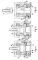
Die in den Figuren 1, 2, 4 - 6 dargestellte Schnellspanneinheit 10 umfasst einen Grundkörper 12, in dem eine Spannaufnahme 14 vorgesehen ist. In die Spannaufnahme 14 ist ein Spannbolzen 16 einführbar, der über zwei einander gegenüberliegende Spannelemente 18, die als Spannschieber ausgebildet sind, in der Schnellspanneinheit 10 verriegelbar ist. Die Figuren 2 und 4 zeigen dabei den Spannbolzen 16 in verriegelter, die Figuren 5 und 6 in entriegelter Stellung.The quick-
Um ein vereinfachtes Einführen des Spannbolzens 16 in die Spannaufnahme 14 zu ermöglichen und zudem ein konzentrisches Spannen des Spannbolzens 16 zu erreichen, ist der die Spannaufnahme 14 bildende Bereich 20 des Grundkörpers 12 leicht konisch ausgebildet.In order to allow a simplified insertion of the clamping
Zur Verriegelung des Spannbolzens 16 sind die beiden Spannelemente 18 in radialer Richtung aufeinander zu in eine Verriegelungslage und voneinander weg in eine Entriegelungslage bewegbar. Hierzu sehen die Spannelemente 18 Schrägführungen 22 vor, die mit entsprechenden, an einem in axialer Richtung gegenüber dem Grundkörper 12 verlagerbaren Zylinderelement 24 vorgesehenen Schrägführungen zusammenwirken. Das Zylinderelement 24 ist dabei auf einem als Hohlkolbenelement 26 ausgebildeten Kolbenelement axial verschieblich angeordnet. Das Hohlkolbenelement 26, das konzentrisch um die Mittellängsachse 28 gegenüber dem Grundkörper 12 feststehend angeordnet ist, weist einen in nach radial außen gewandter Richtung abstehenden, ringbundartigen Kolbenabschnitt 30 auf. Zur Begrenzung eines mit einem Druckmittel, insbesondere mit Druckluft oder mit Hydraulikflüssigkeit, beaufschlagbaren Druckraums 32 zwischen dem Hohlkolbenelement 26 beziehungsweise dessen Kolbenabschnitt 30 und dem Zylinderelement 24 weist das Zylinderelement 24 ein das Hohlkolbenelement 26 ringartig umgebendes Deckelelement 34 auf. Das Deckelelement 34 wird über einen Spannring 35 am Zylinderelement 24 befestigt.For locking the clamping
Aus Figur 2 wird ferner deutlich, dass die der Spannaufnahme 14 zugewandte Seite 27 des Hohlkolbenelements 26 sich in Verlängerung der Spannaufnahme 14 erstreckt und zur Axialführung des in die Spannaufnahme 14 eingreifenden Spannbolzens 16 dient. Das Hohlkolbenelement 26 sieht dabei an seinem oberen Rand Führungsschrägen als Einführhilfe für den,Spannbolzen 16 vor.It is also clear from FIG. 2 that the
Wie insbesondere aus den Figuren 1 und 2 deutlich wird, sind zwischen dem Zylinderelement 24 und dem Kolbenabschnitt 30 des Hohlkolbenelements 26 mehrere koaxial um die Mittellängsachse 28 angeordnete Federelemente 36 vorgesehen, die das Zylinderelement 24 nach axial oben beaufschlagen. Das Zylinderelement 24 ist innerhalb eines grundkörperseitigen Zylinderraums 38 axial bewegbar angeordnet. Der Zylinderraum 38 ist auf seiner axial unteren Seite mit einem Verschlusselement 40 verschlossen, durch welches das Hohlkolbenelement 26 am Grundkörper 12 festgesetzt ist. Die eine Stirnseite des Hohlkolbenelements 26 wirkt dabei gegen den Grundkörper 12 und die andere Stirnseite des Hohlkolbenelements 26 gegen das Verschlusselement 40.As is clear in particular from Figures 1 and 2, 26 a plurality of coaxially disposed about the central
Das Verschlusselement 40 weist im Bereich der Mittellängsachse 28 einen Durchbruch 42 hin zum Innenraum 44 des Hohlkolbenelements 26 auf. Im Innenraum 44 kann, wie in den Figuren 12 - 14 dargestellt ist, beispielsweise eine Verschlusseinheit zum Verschließen der Spannaufnahme 14 vorgesehen sein. Ferner können andere Baugruppen oder Einheiten, beispielsweise eine Überwachungskamera oder Überwachungssensoren, im Innenraum 44 angeordnet werden.In the region of the central
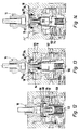
Die in der Figur 3 dargestellte Schnellspanneinheit 50 entspricht im Wesentlichen der Schnellspanneinheit 10 gemäß Figur 1 und 2, wobei entsprechende Bauteile mit entsprechenden Bezugszeichen gekennzeichnet sind. Grundlegender Unterschied ist, dass der Grundkörper 12 keinen Zylinderraum 38 für das Zylinderelement 24 aufweist. Vielmehr ist auf der dem Druckraum 32 abgewandten Seite des Kolbenabschnitts 30 ein zweiter Druckraum 52 vorgesehen, der zur Bewegung des Zylinderelements 24 nach axial oben druckbeaufschlagbar ist. Zur Bewegung des Zylinderelements 24 nach axial unten ist der Druckraum 32 druckbeaufschlagbar. Das Hohlkolbenelement 26 kann dabei an den Grundkörper 12 angeflanscht sein.The quick-clamping
Die Figuren 4 - 6 zeigen verschiedene Betriebszustände der Schnellspanneinheit 10 gemäß Figur 1 und 2. In der Figur 4 ist die Schnellspanneinheit 10 mit in der Spannaufnahme 14 verriegeltem Spannbolzen 16 dargestellt. Die Spannelemente 18 befinden sich dabei in ihrer radial innen liegenden Verriegelungsstellung. Auch ohne Druckbeaufschlagung des Zylinderraums 38 wird aufgrund der Federkraft der Federelemente 36 diese Verriegelungsstellung selbsttätig aufrechterhalten. Wird nun, wie in Figur 5 gezeigt, der Druckraum 32 über eine mit dem Druckraum 32 verbundene Druckleitung 60 druckbeaufschlagt, so bewegt sich das Zylinderelement 24 nach axial unten. Aufgrund der Schrägführungen 22 bewegen sich zeitgleich die Spannelemente 18 nach radial außen in ihre Entriegelungslage. Der Spannbolzen 16 wird dadurch freigegeben und kann, wie in Figur 6 dargestellt, aus der Spannaufnahme 14 entnommen werden.FIGS. 4 to 6 show different operating states of the quick-
Zur Verlagerung der Spannelemente 18 aus der Entriegelungslage in die Verriegelungslage wird der Druckraum 32 druckfrei geschaltet. Zur Unterstützung der durch die Federelemente 36 aufgebrachten Federkraft wird zudem über eine ebenfalls im Grundkörper 12 vorgesehene Druckleitung 62, wie in der Figur 4 und 6 dargestellt, der Zylinderraum 38 mit Druck beaufschlagt. Bei der Schnellspanneinheit 50 gemäß Figur 3 wird, wie bereits erwähnt, im Gegensatz hierzu, zur Bewegung des Zylinderelements nach axial oben der Druckraum 52 druckbeaufschlagt.To displace the
Zur Druckbeaufschlagung des Druckraums 32 bei beliebiger Stellung des Zylinderelements 24 auf dem Hohlkolbenelement 26 weist das Zylinderelement 24 einen auf seiner radial außen gelegenen Seite einen Druckzwischenraum 64 auf, der nach axial oben und axial unten von zwei umlaufenden Ringbünden 66 begrenzt wird. Der Druckzwischenraum 64 ist so angeordnet, dass in jeder Drucklage des Zylinderelements 24 dieser Druckzwischenraum 64 mit der Druckleitung 60 korrespondiert. Im Bereich des Druckzwischenraumes 64 ist ein Durchbruch 68 am Zylinderelement 24 vorgesehen, durch welchen das Druckmittel in den Druckraum 32 gelangt.To pressurize the
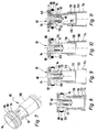
In den Figuren 7 - 11 ist eine Verschlusseinheit 80 zur Anordnung in den Innenraum 44 der Spanneinheit 10 gemäß den Figuren 1, 2 und 4 - 6 dargestellt. Die Verschlusseinheit 80 umfasst dabei ein auf einem Trägerteil 82 axial zwischen einer in den Figuren 8 und 9 dargestellten Einführlage und einer in den Figuren 10 und 11 dargestellten Verschlusslage bewegbares, ringartig ausgebildetes Druckelement 84. Zwischen dem Druckelement 84 und einem in radialer Richtung abstehenden Rand 86 des Trägerteils 82 ist ein balgartig ausgebildetes elastisches Dichtungselement 88 angeordnet. Das Trägerteil selbst kann dabei, wie in den Figuren gezeigt, mehrteilig ausgebildet sein.FIGS. 7-11 show a
In der Einführlage des Druckelements überragt das Dichtungselement 88 das Druckelement 84 beziehungsweise den Rand 86 in radial Richtung nicht oder nur unwesentlich. In der in den Figuren 10 und 11 dargestellten Verschlusslage des Druckelements wird das Dichtungselement 88 nach radial außen gedrückt und überragt in radialer Richtung das Druckelement 84 sowie den Rand 86.In the insertion position of the pressure element, the sealing
Wie aus den Figuren 8 - 11 deutlich wird, ist im Trägerteil 82 ein das Trägerteil 82 durchgreifender, axial unter der Vorspannung einer Feder 90 angeordneter Ventilkörper 92 angeordnet. Der Ventilkörper 92 umfasst eine sich in radialer Richtung erstreckende Ventilplatte 94, die die Oberseite des Trägerteils 82 weitgehend vollständig abdeckt. Ferner umfasst der Ventilkörper 92 eine sich in axialer Richtung erstreckende Ventilstange 96, die im Bereich der Mittellängsachse 98 verläuft und das Trägerteil 82 in axialer Richtung durchgreift. Findet eine Druckerhöhung innerhalb des Trägerteils 82 statt, so hebt im in einer Spanneinheit eingebauten Zustand der Ventilkörper 92 von der Oberseite des Trägerteils 82 ab, wodurch Luft 83 aus dem Inneren des Trägerteils 82 zwischen der Ventilplatte 94 und der Oberseite des Trägerteils 82 in radialer Richtung, wie in Figur 11 angedeutet, ausströmen kann. Hierdurch kann ein Entfernen von Spänen und Verschmutzungen erzielt werden.As is clear from FIGS. 8-11, a
Das Trägerteil 82 samt Ventilkörper 92 und Druckelement 84 ist von einer Ruhelage, die in Figur 8 dargestellt ist, nach axial oben in eine in den Figuren 9 - 11 dargestellte Aktivierungslage überführbar. Zur gezielten Bewegungsführung ist hierfür ein teleskopartig ausgebildetes Zwischenteil 100 vorgesehen, das einerseits mit dem Trägerteil 82 und andererseits bei in die Spanneinheit 10 eingebautem Zustand mit dem Hohlkolbenelement 26, wie in den Figuren 12 - 14 dargestellt, zusammenwirkt.The
In den Figuren 12 - 14 ist die in den Figuren 7 - 11 gezeigte Verschlusseinheit in die in den Figuren 1, 2 und 4 - 6 gezeigte Schnellspanneinheit 10 eingesetzt. Die Verschlusseinheit befindet sich dabei vollständig im Innenraum 44 des Hohlkolbenelements 26. Zur Verlagerung des Zwischenelements 100 und des Trägerteils 82 aus der Ruhelage in die Aktivierungslage ist ein Federelement 102 vorgesehen, das sich einerseits an der Innenseite des Verschlusselements 40 und andererseits an der dem Verschlusselement 40 zugewandten Seite des Trägerteils 82 abstützt. Die Ruhelage des Trägerteils 82 ist dabei in der Figur 12 dargestellt, in der der Spannbolzen 16 in verriegeltem Zustand in der Schnellspanneinheit 10 angeordnet ist. Werden nun die Spannelemente 18 aufgrund einer Druckbeaufschlagung des Druckraums 32 in ihre Entriegelungslage verfahren und wird der Spannbolzen 16 in axialer Richtung aus der Spannaufnahme 14 entnommen, so wird aufgrund des Federelements 102 das Trägerteil 82 in die Aktivierungslage, in der es sich in der Spannaufnahme 14 befindet, entsprechend Figur 13 bewegt. In diesem Zustand befindet sich allerdings noch ein Spalt zwischen dem der Spannaufnahme 14 begrenzenden Bereich 20 des Grundkörpers 12 und dem Dichtungselement 88. Werden nun, wie in Figur 14 dargestellt, die Spannelemente 18 beispielsweise aufgrund der Federkraft der Federelemente 36 und/oder aufgrund einer Druckbeaufschlagung des Zylinderraums 38 in ihre Verriegelungslage überführt, so wird das Druckelement 84 von den Spannelementen 18 nach axial oben in die Verschlusslage bewegt. Hierzu sind an den Spannelementen 18 Führungsschrägen 104 sowie am Druckelement 84 ein mit den Führungsschrägen 104 korrespondierender konusartig umlaufender Führungsabschnitt 106 vorgesehen.In FIGS. 12-14, the closure unit shown in FIGS. 7-11 is inserted into the quick-
Wie aus Figur 14 deutlich wird, wird in der Verschlusslage des Druckelements 84 das Dichtungselement 88 nach radial außen gegen die die Spannaufnahme 14 begrenzende Wandung 20 des Grundkörpers 12 wenigstens weitgehend dicht beaufschlagt. Hierdurch wird unterbunden, dass Späne oder Verschmutzungen über die Spannaufnahme 14 in die Schnellspanneinheit 10 eindringen können.As is clear from FIG. 14, in the closed position of the
Zur axialen Hubbegrenzung des Zwischenteils 100 innerhalb des Hohlkolbenelements 26 weist das Hohlkolbenelement 26 einen umlaufenden Anschlag 112 auf, der in der Aktivierungslage des Trägerteils 82 beziehungsweise des Zwischenelements 100 mit einem zwischenteilseitigen Ringbund 114, wie in Figur 14 dargestellt, zusammenwirkt. Entsprechend weist das Zwischenteil 100 an seinem axialen oberen Ende einen nach innen ragenden Anschlag 116 auf, der in der Aktivierungslage mit einem an der unteren Seite des Zwischenteils 82 angeordneten, einen Gegenanschlag 118 aufweisenden Ringbund 120 zusammenwirkt, wie in den Figuren 9, 10, 11 und 13, 14 gezeigt ist.For the axial stroke limitation of the
Um auf der Oberseite 108 des Grundkörpers 12 auftretende Verschmutzungen oder Späne zu entfernen, kann, wie zur Figur 11 erläutert, der Innenraum 110 des Trägerteils 82 beziehungsweise des Hohlkolbenelements 26 mit Druckluft beaufschlagt werden, wodurch der Ventilkörper 92 entgegen der Federkraft der Feder 90 abhebt und die Druckluft gegebenenfalls auf der Oberseite 108 vorhandene Verschmutzungen oder Späne wegbläst.To remove on the top 108 of the
Claims (19)
Applications Claiming Priority (1)
| Application Number | Priority Date | Filing Date | Title |
|---|---|---|---|
| DE102006037708A DE102006037708A1 (en) | 2006-08-08 | 2006-08-08 | Quick clamping unit, locking unit for this and quick clamping system |
Publications (3)
| Publication Number | Publication Date |
|---|---|
| EP1886751A2 true EP1886751A2 (en) | 2008-02-13 |
| EP1886751A3 EP1886751A3 (en) | 2008-08-06 |
| EP1886751B1 EP1886751B1 (en) | 2009-10-07 |
Family
ID=38564381
Family Applications (1)
| Application Number | Title | Priority Date | Filing Date |
|---|---|---|---|
| EP07015177A Active EP1886751B1 (en) | 2006-08-08 | 2007-08-02 | Quick acting clamping device, closing unit and system for quick clamping |
Country Status (4)
| Country | Link |
|---|---|
| US (1) | US8152174B2 (en) |
| EP (1) | EP1886751B1 (en) |
| AT (1) | ATE444825T1 (en) |
| DE (2) | DE102006037708A1 (en) |
Cited By (10)
| Publication number | Priority date | Publication date | Assignee | Title |
|---|---|---|---|---|
| EP2357058A1 (en) * | 2010-02-12 | 2011-08-17 | Schunk GmbH & Co. KG Spann- und Greiftechnik | Clamping system particularly zero point clamping system |
| DE202013009825U1 (en) | 2013-12-05 | 2014-02-10 | Color Metal Gmbh | Distance and clamping bolts for 5-axis machining with zero point clamping systems |
| EP2777850A1 (en) * | 2013-03-14 | 2014-09-17 | Schunk GmbH & Co. KG Spann- und Greiftechnik | Clamping or gripping device |
| EP2777849A1 (en) * | 2013-03-14 | 2014-09-17 | Schunk GmbH & Co. KG Spann- und Greiftechnik | Clamping or gripping device |
| EP2777848A1 (en) * | 2013-03-14 | 2014-09-17 | Schunk GmbH & Co. KG Spann- und Greiftechnik | Clamping or gripping device |
| EP3081329A3 (en) * | 2015-04-14 | 2017-01-18 | Schunk GmbH & Co. KG Spann- und Greiftechnik | Clamping module and clamping system in particular zero point clamping system |
| CN111958272A (en) * | 2019-05-20 | 2020-11-20 | Smw-奥托布洛克紧固系统有限责任公司 | Zero point clamping device |
| EP3741501A1 (en) | 2019-05-20 | 2020-11-25 | SMW-AUTOBLOK Spannsysteme GmbH | Zero point clamping device |
| EP3778082A1 (en) | 2019-08-14 | 2021-02-17 | SMW-AUTOBLOK Spannsysteme GmbH | Zero point clamping device |
| DE202018006687U1 (en) | 2017-06-26 | 2022-02-17 | Schunk Gmbh & Co. Kg Spann- Und Greiftechnik | Quick-change pallet module and locking device |
Families Citing this family (14)
| Publication number | Priority date | Publication date | Assignee | Title |
|---|---|---|---|---|
| DE102010045018B4 (en) | 2009-11-27 | 2013-05-16 | Schunk Gmbh & Co. Kg Spann- Und Greiftechnik | Clamping and gripping device |
| DE102009057198B3 (en) * | 2009-11-27 | 2011-06-16 | Schunk Gmbh & Co. Kg Spann- Und Greiftechnik | Quick clamping unit for determining whether clamping slide is in clamping position or in release position, has channel in which pressure is applied, and pressure and air in release position comprising values than in clamping position |
| DE102010010898C5 (en) | 2010-03-05 | 2017-04-13 | Schunk Gmbh & Co. Kg | Pallet System |
| DE102011108341B4 (en) | 2011-07-22 | 2016-05-12 | Stark Spannsysteme Gmbh | Clamping device and corresponding retractable nipple |
| DE102011080502B4 (en) * | 2011-08-05 | 2015-03-12 | Schunk Gmbh & Co. Kg Spann- Und Greiftechnik | Clamping device and pallet handling system |
| DE102011080504B4 (en) * | 2011-08-05 | 2020-10-15 | Schunk Gmbh & Co. Kg Spann- Und Greiftechnik | Clamping device and pallet handling system |
| DE102013222952B4 (en) | 2013-11-12 | 2018-11-29 | Schunk Gmbh & Co. Kg Spann- Und Greiftechnik | Clamping module of a clamping system, in particular a zero point system, with an elastic support surface |
| DE102013226412B4 (en) | 2013-12-18 | 2021-11-18 | Schunk Gmbh & Co. Kg Spann- Und Greiftechnik | Clamping module, in particular zero point clamping module and associated clamping system |
| CN111974889B (en) * | 2019-05-21 | 2022-08-26 | 乔升机器股份有限公司 | Pipe fitting end clamping device |
| US11052499B2 (en) * | 2019-06-24 | 2021-07-06 | Chiao Sheng Machinery Co., Ltd. | Pipe end clamping apparatus |
| DE102021121686A1 (en) | 2021-08-20 | 2023-02-23 | Heinz-Dieter Schunk Gmbh & Co. Spanntechnik Kg | Sensor device for detecting the position of a clamping element of a clamping or gripping device and clamping or gripping device |
| DE102021121688A1 (en) | 2021-08-20 | 2023-02-23 | Heinz-Dieter Schunk Gmbh & Co. Spanntechnik Kg | Electronic module, clamping or gripping device with electronic module and construction kit |
| DE102021121687B3 (en) | 2021-08-20 | 2022-11-17 | Heinz-Dieter Schunk Gmbh & Co. Spanntechnik Kg | Space-saving clamping module with electronic component group |
| DE102022113844B3 (en) | 2022-06-01 | 2023-06-01 | Heinz-Dieter Schunk Gmbh & Co. Spanntechnik Kg | Flat clamping device with a detachable guide element containing a guide groove |
Citations (2)
| Publication number | Priority date | Publication date | Assignee | Title |
|---|---|---|---|---|
| DE202004009283U1 (en) | 2004-06-11 | 2004-08-26 | Berg & Co Gmbh | Clamping device to hold components on palettes for moving into processing stations has ring segment-shaped clamping parts moved between clamping and release positions by vertically moving locking piston |
| DE10317336A1 (en) | 2003-04-15 | 2004-11-04 | Ssa System-Spann Ag | High-speed clamping cylinder with exhaust for removing fragments and pollutants from an internal space, has air chambers formed at bottom side of housing and extended across total bottom portion of housing |
Family Cites Families (6)
| Publication number | Priority date | Publication date | Assignee | Title |
|---|---|---|---|---|
| DE8014064U1 (en) * | 1980-05-24 | 1980-08-21 | Roehm, Guenter Horst, 7927 Sontheim | TOOL CLAMP |
| FR2556065B1 (en) * | 1983-12-01 | 1986-09-12 | Alsthom Atlantique | MECHANICAL CONNECTION DEVICE |
| US5522605A (en) * | 1994-08-10 | 1996-06-04 | Kennametal Inc. | Collet chuck having parpallel force loaded bearing |
| JP4146922B2 (en) * | 1996-12-02 | 2008-09-10 | システム・3アル・インテルナショナール・アクチボラグ | Clamp system |
| US6637755B2 (en) * | 2002-03-22 | 2003-10-28 | Tsai-Ching Chen | Chuck device for miniature tool bits |
| US20040026878A1 (en) * | 2002-03-22 | 2004-02-12 | Tsai-Ching Chen | Chuck device for miniature tool bits |
-
2006
- 2006-08-08 DE DE102006037708A patent/DE102006037708A1/en not_active Ceased
-
2007
- 2007-08-02 AT AT07015177T patent/ATE444825T1/en active
- 2007-08-02 EP EP07015177A patent/EP1886751B1/en active Active
- 2007-08-02 DE DE502007001664T patent/DE502007001664D1/en active Active
- 2007-08-06 US US11/882,768 patent/US8152174B2/en active Active
Patent Citations (2)
| Publication number | Priority date | Publication date | Assignee | Title |
|---|---|---|---|---|
| DE10317336A1 (en) | 2003-04-15 | 2004-11-04 | Ssa System-Spann Ag | High-speed clamping cylinder with exhaust for removing fragments and pollutants from an internal space, has air chambers formed at bottom side of housing and extended across total bottom portion of housing |
| DE202004009283U1 (en) | 2004-06-11 | 2004-08-26 | Berg & Co Gmbh | Clamping device to hold components on palettes for moving into processing stations has ring segment-shaped clamping parts moved between clamping and release positions by vertically moving locking piston |
Cited By (16)
| Publication number | Priority date | Publication date | Assignee | Title |
|---|---|---|---|---|
| EP2357058A1 (en) * | 2010-02-12 | 2011-08-17 | Schunk GmbH & Co. KG Spann- und Greiftechnik | Clamping system particularly zero point clamping system |
| EP2777850A1 (en) * | 2013-03-14 | 2014-09-17 | Schunk GmbH & Co. KG Spann- und Greiftechnik | Clamping or gripping device |
| EP2777849A1 (en) * | 2013-03-14 | 2014-09-17 | Schunk GmbH & Co. KG Spann- und Greiftechnik | Clamping or gripping device |
| EP2777848A1 (en) * | 2013-03-14 | 2014-09-17 | Schunk GmbH & Co. KG Spann- und Greiftechnik | Clamping or gripping device |
| DE202013009825U1 (en) | 2013-12-05 | 2014-02-10 | Color Metal Gmbh | Distance and clamping bolts for 5-axis machining with zero point clamping systems |
| EP3081329A3 (en) * | 2015-04-14 | 2017-01-18 | Schunk GmbH & Co. KG Spann- und Greiftechnik | Clamping module and clamping system in particular zero point clamping system |
| DE202018006687U1 (en) | 2017-06-26 | 2022-02-17 | Schunk Gmbh & Co. Kg Spann- Und Greiftechnik | Quick-change pallet module and locking device |
| EP3741502A1 (en) | 2019-05-20 | 2020-11-25 | SMW-AUTOBLOK Spannsysteme GmbH | Zero point clamping device |
| EP3741501A1 (en) | 2019-05-20 | 2020-11-25 | SMW-AUTOBLOK Spannsysteme GmbH | Zero point clamping device |
| US11247306B2 (en) | 2019-05-20 | 2022-02-15 | Smw-Autoblok Spannsysteme Gmbh | Zero-point clamping device |
| CN111958272A (en) * | 2019-05-20 | 2020-11-20 | Smw-奥托布洛克紧固系统有限责任公司 | Zero point clamping device |
| EP3778082A1 (en) | 2019-08-14 | 2021-02-17 | SMW-AUTOBLOK Spannsysteme GmbH | Zero point clamping device |
| US20210046594A1 (en) * | 2019-08-14 | 2021-02-18 | Smw-Autoblok Spannsysteme Gmbh | Zero-point clamping device |
| CN112388348A (en) * | 2019-08-14 | 2021-02-23 | Smw-奥托布洛克紧固系统有限责任公司 | Zero point clamping device |
| US11618115B2 (en) * | 2019-08-14 | 2023-04-04 | Smw-Autoblok Spannsysteme Gmbh | Zero-point clamping device |
| CN112388348B (en) * | 2019-08-14 | 2023-08-04 | Smw-奥托布洛克紧固系统有限责任公司 | Zero clamping device |
Also Published As
| Publication number | Publication date |
|---|---|
| US8152174B2 (en) | 2012-04-10 |
| ATE444825T1 (en) | 2009-10-15 |
| DE502007001664D1 (en) | 2009-11-19 |
| US20080036163A1 (en) | 2008-02-14 |
| DE102006037708A1 (en) | 2008-02-14 |
| EP1886751A3 (en) | 2008-08-06 |
| EP1886751B1 (en) | 2009-10-07 |
Similar Documents
| Publication | Publication Date | Title |
|---|---|---|
| EP1886751B1 (en) | Quick acting clamping device, closing unit and system for quick clamping | |
| EP1707307B1 (en) | Quick clamp system | |
| DE102006061017A1 (en) | Actuator and method for adjusting a maximum displacement of a drive rod of an actuator of the actuator | |
| DE2540722C2 (en) | Double lid for closing two openings that can be connected to one another | |
| EP2713061B1 (en) | Closure and cladding system with same | |
| WO2005085653A1 (en) | Safety unit | |
| EP0855243A2 (en) | Clamping arrangement, particularly for workpieces | |
| DE202010000254U1 (en) | tire valve | |
| EP3482872B1 (en) | Neutral point tensioning module | |
| DE102007015975B4 (en) | Hydraulic clamping device for tightening screws | |
| DE102010005886A1 (en) | Clamping device with a height compensation | |
| DE112009005287T5 (en) | Belt coupling and pressure vessel equipped therewith | |
| EP1577054B1 (en) | Clamp cylinder with cover cap | |
| DE2706884A1 (en) | PNEUMATIC SPRING | |
| EP0446448B1 (en) | Connection device for pipes under pressure or equivalent | |
| DE102007031463A1 (en) | Pressurized medium cylinder e.g. simple-working pressurized medium cylinder, for use in e.g. quick-action clamping cylinder, has locking unit for locking piston in one of end positions or intermediate position between end positions | |
| DE102009033263A1 (en) | Gas or liquid e.g. fuel, filtering device for vehicle, has bypass valve including auxiliary lifter formed as separate component, and valve body that acts upon auxiliary lifter in closed position and closes flow opening | |
| DE102016125269A1 (en) | Clamping or gripping device | |
| DE3510643A1 (en) | Clamping head | |
| DE19817822C2 (en) | Tire heating press | |
| DE2655284A1 (en) | PNEUMATIC OR HYDRAULIC AND SINGLE OR DOUBLE PISTON-CYLINDER DEVICE | |
| DE4215031C2 (en) | Lockable piston actuator for transporting a roll bar for motor vehicles | |
| DE4400357A1 (en) | Disengaging device with hydraulic actuator for engaging a traction clutch | |
| DE3200842A1 (en) | AXIAL COMPENSATOR WITH TENSIONING DEVICE | |
| DE20105949U1 (en) | Piston-cylinder unit actuated by pressure medium, in particular pneumatically |
Legal Events
| Date | Code | Title | Description |
|---|---|---|---|
| PUAI | Public reference made under article 153(3) epc to a published international application that has entered the european phase |
Free format text: ORIGINAL CODE: 0009012 |
|
| AK | Designated contracting states |
Kind code of ref document: A2 Designated state(s): AT BE BG CH CY CZ DE DK EE ES FI FR GB GR HU IE IS IT LI LT LU LV MC MT NL PL PT RO SE SI SK TR |
|
| AX | Request for extension of the european patent |
Extension state: AL BA HR MK YU |
|
| PUAL | Search report despatched |
Free format text: ORIGINAL CODE: 0009013 |
|
| AK | Designated contracting states |
Kind code of ref document: A3 Designated state(s): AT BE BG CH CY CZ DE DK EE ES FI FR GB GR HU IE IS IT LI LT LU LV MC MT NL PL PT RO SE SI SK TR |
|
| AX | Request for extension of the european patent |
Extension state: AL BA HR MK RS |
|
| RIC1 | Information provided on ipc code assigned before grant |
Ipc: B23Q 1/00 20060101ALI20080702BHEP Ipc: B23Q 11/08 20060101ALI20080702BHEP Ipc: B23B 31/16 20060101AFI20071018BHEP |
|
| 17P | Request for examination filed |
Effective date: 20080906 |
|
| 17Q | First examination report despatched |
Effective date: 20081009 |
|
| GRAP | Despatch of communication of intention to grant a patent |
Free format text: ORIGINAL CODE: EPIDOSNIGR1 |
|
| AKX | Designation fees paid |
Designated state(s): AT BE BG CH CY CZ DE DK EE ES FI FR GB GR HU IE IS IT LI LT LU LV MC MT NL PL PT RO SE SI SK TR |
|
| GRAS | Grant fee paid |
Free format text: ORIGINAL CODE: EPIDOSNIGR3 |
|
| GRAA | (expected) grant |
Free format text: ORIGINAL CODE: 0009210 |
|
| AK | Designated contracting states |
Kind code of ref document: B1 Designated state(s): AT BE BG CH CY CZ DE DK EE ES FI FR GB GR HU IE IS IT LI LT LU LV MC MT NL PL PT RO SE SI SK TR |
|
| REG | Reference to a national code |
Ref country code: GB Ref legal event code: FG4D Free format text: NOT ENGLISH |
|
| REG | Reference to a national code |
Ref country code: CH Ref legal event code: EP Ref country code: CH Ref legal event code: NV Representative=s name: MICHELI & CIE SA |
|
| REG | Reference to a national code |
Ref country code: IE Ref legal event code: FG4D |
|
| REF | Corresponds to: |
Ref document number: 502007001664 Country of ref document: DE Date of ref document: 20091119 Kind code of ref document: P |
|
| PG25 | Lapsed in a contracting state [announced via postgrant information from national office to epo] |
Ref country code: SI Free format text: LAPSE BECAUSE OF FAILURE TO SUBMIT A TRANSLATION OF THE DESCRIPTION OR TO PAY THE FEE WITHIN THE PRESCRIBED TIME-LIMIT Effective date: 20091007 |
|
| NLV1 | Nl: lapsed or annulled due to failure to fulfill the requirements of art. 29p and 29m of the patents act | ||
| LTIE | Lt: invalidation of european patent or patent extension |
Effective date: 20091007 |
|
| PG25 | Lapsed in a contracting state [announced via postgrant information from national office to epo] |
Ref country code: SE Free format text: LAPSE BECAUSE OF FAILURE TO SUBMIT A TRANSLATION OF THE DESCRIPTION OR TO PAY THE FEE WITHIN THE PRESCRIBED TIME-LIMIT Effective date: 20091007 Ref country code: PT Free format text: LAPSE BECAUSE OF FAILURE TO SUBMIT A TRANSLATION OF THE DESCRIPTION OR TO PAY THE FEE WITHIN THE PRESCRIBED TIME-LIMIT Effective date: 20100208 Ref country code: LT Free format text: LAPSE BECAUSE OF FAILURE TO SUBMIT A TRANSLATION OF THE DESCRIPTION OR TO PAY THE FEE WITHIN THE PRESCRIBED TIME-LIMIT Effective date: 20091007 Ref country code: IS Free format text: LAPSE BECAUSE OF FAILURE TO SUBMIT A TRANSLATION OF THE DESCRIPTION OR TO PAY THE FEE WITHIN THE PRESCRIBED TIME-LIMIT Effective date: 20100207 Ref country code: FI Free format text: LAPSE BECAUSE OF FAILURE TO SUBMIT A TRANSLATION OF THE DESCRIPTION OR TO PAY THE FEE WITHIN THE PRESCRIBED TIME-LIMIT Effective date: 20091007 Ref country code: ES Free format text: LAPSE BECAUSE OF FAILURE TO SUBMIT A TRANSLATION OF THE DESCRIPTION OR TO PAY THE FEE WITHIN THE PRESCRIBED TIME-LIMIT Effective date: 20100118 |
|
| REG | Reference to a national code |
Ref country code: IE Ref legal event code: FD4D |
|
| PG25 | Lapsed in a contracting state [announced via postgrant information from national office to epo] |
Ref country code: LV Free format text: LAPSE BECAUSE OF FAILURE TO SUBMIT A TRANSLATION OF THE DESCRIPTION OR TO PAY THE FEE WITHIN THE PRESCRIBED TIME-LIMIT Effective date: 20091007 Ref country code: PL Free format text: LAPSE BECAUSE OF FAILURE TO SUBMIT A TRANSLATION OF THE DESCRIPTION OR TO PAY THE FEE WITHIN THE PRESCRIBED TIME-LIMIT Effective date: 20091007 |
|
| PG25 | Lapsed in a contracting state [announced via postgrant information from national office to epo] |
Ref country code: EE Free format text: LAPSE BECAUSE OF FAILURE TO SUBMIT A TRANSLATION OF THE DESCRIPTION OR TO PAY THE FEE WITHIN THE PRESCRIBED TIME-LIMIT Effective date: 20091007 Ref country code: BG Free format text: LAPSE BECAUSE OF FAILURE TO SUBMIT A TRANSLATION OF THE DESCRIPTION OR TO PAY THE FEE WITHIN THE PRESCRIBED TIME-LIMIT Effective date: 20100107 Ref country code: IE Free format text: LAPSE BECAUSE OF FAILURE TO SUBMIT A TRANSLATION OF THE DESCRIPTION OR TO PAY THE FEE WITHIN THE PRESCRIBED TIME-LIMIT Effective date: 20091007 Ref country code: DK Free format text: LAPSE BECAUSE OF FAILURE TO SUBMIT A TRANSLATION OF THE DESCRIPTION OR TO PAY THE FEE WITHIN THE PRESCRIBED TIME-LIMIT Effective date: 20091007 Ref country code: RO Free format text: LAPSE BECAUSE OF FAILURE TO SUBMIT A TRANSLATION OF THE DESCRIPTION OR TO PAY THE FEE WITHIN THE PRESCRIBED TIME-LIMIT Effective date: 20091007 Ref country code: NL Free format text: LAPSE BECAUSE OF FAILURE TO SUBMIT A TRANSLATION OF THE DESCRIPTION OR TO PAY THE FEE WITHIN THE PRESCRIBED TIME-LIMIT Effective date: 20091007 |
|
| PLBE | No opposition filed within time limit |
Free format text: ORIGINAL CODE: 0009261 |
|
| STAA | Information on the status of an ep patent application or granted ep patent |
Free format text: STATUS: NO OPPOSITION FILED WITHIN TIME LIMIT |
|
| PG25 | Lapsed in a contracting state [announced via postgrant information from national office to epo] |
Ref country code: SK Free format text: LAPSE BECAUSE OF FAILURE TO SUBMIT A TRANSLATION OF THE DESCRIPTION OR TO PAY THE FEE WITHIN THE PRESCRIBED TIME-LIMIT Effective date: 20091007 Ref country code: CZ Free format text: LAPSE BECAUSE OF FAILURE TO SUBMIT A TRANSLATION OF THE DESCRIPTION OR TO PAY THE FEE WITHIN THE PRESCRIBED TIME-LIMIT Effective date: 20091007 |
|
| 26N | No opposition filed |
Effective date: 20100708 |
|
| PG25 | Lapsed in a contracting state [announced via postgrant information from national office to epo] |
Ref country code: GR Free format text: LAPSE BECAUSE OF FAILURE TO SUBMIT A TRANSLATION OF THE DESCRIPTION OR TO PAY THE FEE WITHIN THE PRESCRIBED TIME-LIMIT Effective date: 20100108 |
|
| BERE | Be: lapsed |
Owner name: SCHUNK G.M.B.H. & CO. KG SPANN- UND GREIFTECHNIK Effective date: 20100831 |
|
| PG25 | Lapsed in a contracting state [announced via postgrant information from national office to epo] |
Ref country code: MC Free format text: LAPSE BECAUSE OF NON-PAYMENT OF DUE FEES Effective date: 20100831 |
|
| PG25 | Lapsed in a contracting state [announced via postgrant information from national office to epo] |
Ref country code: BE Free format text: LAPSE BECAUSE OF NON-PAYMENT OF DUE FEES Effective date: 20100831 |
|
| PG25 | Lapsed in a contracting state [announced via postgrant information from national office to epo] |
Ref country code: MT Free format text: LAPSE BECAUSE OF FAILURE TO SUBMIT A TRANSLATION OF THE DESCRIPTION OR TO PAY THE FEE WITHIN THE PRESCRIBED TIME-LIMIT Effective date: 20091007 |
|
| GBPC | Gb: european patent ceased through non-payment of renewal fee |
Effective date: 20110802 |
|
| PG25 | Lapsed in a contracting state [announced via postgrant information from national office to epo] |
Ref country code: CY Free format text: LAPSE BECAUSE OF FAILURE TO SUBMIT A TRANSLATION OF THE DESCRIPTION OR TO PAY THE FEE WITHIN THE PRESCRIBED TIME-LIMIT Effective date: 20091007 Ref country code: GB Free format text: LAPSE BECAUSE OF NON-PAYMENT OF DUE FEES Effective date: 20110802 |
|
| PG25 | Lapsed in a contracting state [announced via postgrant information from national office to epo] |
Ref country code: HU Free format text: LAPSE BECAUSE OF FAILURE TO SUBMIT A TRANSLATION OF THE DESCRIPTION OR TO PAY THE FEE WITHIN THE PRESCRIBED TIME-LIMIT Effective date: 20100408 Ref country code: LU Free format text: LAPSE BECAUSE OF NON-PAYMENT OF DUE FEES Effective date: 20100802 |
|
| PG25 | Lapsed in a contracting state [announced via postgrant information from national office to epo] |
Ref country code: TR Free format text: LAPSE BECAUSE OF FAILURE TO SUBMIT A TRANSLATION OF THE DESCRIPTION OR TO PAY THE FEE WITHIN THE PRESCRIBED TIME-LIMIT Effective date: 20091007 |
|
| REG | Reference to a national code |
Ref country code: FR Ref legal event code: PLFP Year of fee payment: 9 |
|
| REG | Reference to a national code |
Ref country code: FR Ref legal event code: PLFP Year of fee payment: 10 |
|
| REG | Reference to a national code |
Ref country code: FR Ref legal event code: PLFP Year of fee payment: 11 |
|
| REG | Reference to a national code |
Ref country code: FR Ref legal event code: PLFP Year of fee payment: 12 |
|
| P01 | Opt-out of the competence of the unified patent court (upc) registered |
Effective date: 20230628 |
|
| PGFP | Annual fee paid to national office [announced via postgrant information from national office to epo] |
Ref country code: IT Payment date: 20230825 Year of fee payment: 17 Ref country code: CH Payment date: 20230902 Year of fee payment: 17 Ref country code: AT Payment date: 20230822 Year of fee payment: 17 |
|
| PGFP | Annual fee paid to national office [announced via postgrant information from national office to epo] |
Ref country code: FR Payment date: 20230823 Year of fee payment: 17 Ref country code: DE Payment date: 20230821 Year of fee payment: 17 |