EP1886372B1 - Systeme de traitement de combustible - Google Patents
Systeme de traitement de combustible Download PDFInfo
- Publication number
- EP1886372B1 EP1886372B1 EP06727078A EP06727078A EP1886372B1 EP 1886372 B1 EP1886372 B1 EP 1886372B1 EP 06727078 A EP06727078 A EP 06727078A EP 06727078 A EP06727078 A EP 06727078A EP 1886372 B1 EP1886372 B1 EP 1886372B1
- Authority
- EP
- European Patent Office
- Prior art keywords
- combustion
- reformer
- plates
- plate
- reaction
- Prior art date
- Legal status (The legal status is an assumption and is not a legal conclusion. Google has not performed a legal analysis and makes no representation as to the accuracy of the status listed.)
- Not-in-force
Links
Images


Classifications
-
- H—ELECTRICITY
- H01—ELECTRIC ELEMENTS
- H01M—PROCESSES OR MEANS, e.g. BATTERIES, FOR THE DIRECT CONVERSION OF CHEMICAL ENERGY INTO ELECTRICAL ENERGY
- H01M8/00—Fuel cells; Manufacture thereof
- H01M8/06—Combination of fuel cells with means for production of reactants or for treatment of residues
- H01M8/0606—Combination of fuel cells with means for production of reactants or for treatment of residues with means for production of gaseous reactants
- H01M8/0612—Combination of fuel cells with means for production of reactants or for treatment of residues with means for production of gaseous reactants from carbon-containing material
- H01M8/0625—Combination of fuel cells with means for production of reactants or for treatment of residues with means for production of gaseous reactants from carbon-containing material in a modular combined reactor/fuel cell structure
- H01M8/0631—Reactor construction specially adapted for combination reactor/fuel cell
-
- C—CHEMISTRY; METALLURGY
- C01—INORGANIC CHEMISTRY
- C01B—NON-METALLIC ELEMENTS; COMPOUNDS THEREOF; METALLOIDS OR COMPOUNDS THEREOF NOT COVERED BY SUBCLASS C01C
- C01B3/00—Hydrogen; Gaseous mixtures containing hydrogen; Separation of hydrogen from mixtures containing it; Purification of hydrogen
- C01B3/02—Production of hydrogen or of gaseous mixtures containing a substantial proportion of hydrogen
- C01B3/32—Production of hydrogen or of gaseous mixtures containing a substantial proportion of hydrogen by reaction of gaseous or liquid organic compounds with gasifying agents, e.g. water, carbon dioxide, air
- C01B3/34—Production of hydrogen or of gaseous mixtures containing a substantial proportion of hydrogen by reaction of gaseous or liquid organic compounds with gasifying agents, e.g. water, carbon dioxide, air by reaction of hydrocarbons with gasifying agents
- C01B3/38—Production of hydrogen or of gaseous mixtures containing a substantial proportion of hydrogen by reaction of gaseous or liquid organic compounds with gasifying agents, e.g. water, carbon dioxide, air by reaction of hydrocarbons with gasifying agents using catalysts
- C01B3/384—Production of hydrogen or of gaseous mixtures containing a substantial proportion of hydrogen by reaction of gaseous or liquid organic compounds with gasifying agents, e.g. water, carbon dioxide, air by reaction of hydrocarbons with gasifying agents using catalysts the catalyst being continuously externally heated
-
- H—ELECTRICITY
- H01—ELECTRIC ELEMENTS
- H01M—PROCESSES OR MEANS, e.g. BATTERIES, FOR THE DIRECT CONVERSION OF CHEMICAL ENERGY INTO ELECTRICAL ENERGY
- H01M8/00—Fuel cells; Manufacture thereof
- H01M8/04—Auxiliary arrangements, e.g. for control of pressure or for circulation of fluids
- H01M8/04007—Auxiliary arrangements, e.g. for control of pressure or for circulation of fluids related to heat exchange
- H01M8/04014—Heat exchange using gaseous fluids; Heat exchange by combustion of reactants
- H01M8/04022—Heating by combustion
-
- H—ELECTRICITY
- H01—ELECTRIC ELEMENTS
- H01M—PROCESSES OR MEANS, e.g. BATTERIES, FOR THE DIRECT CONVERSION OF CHEMICAL ENERGY INTO ELECTRICAL ENERGY
- H01M8/00—Fuel cells; Manufacture thereof
- H01M8/06—Combination of fuel cells with means for production of reactants or for treatment of residues
- H01M8/0606—Combination of fuel cells with means for production of reactants or for treatment of residues with means for production of gaseous reactants
- H01M8/0612—Combination of fuel cells with means for production of reactants or for treatment of residues with means for production of gaseous reactants from carbon-containing material
- H01M8/0618—Reforming processes, e.g. autothermal, partial oxidation or steam reforming
-
- C—CHEMISTRY; METALLURGY
- C01—INORGANIC CHEMISTRY
- C01B—NON-METALLIC ELEMENTS; COMPOUNDS THEREOF; METALLOIDS OR COMPOUNDS THEREOF NOT COVERED BY SUBCLASS C01C
- C01B2203/00—Integrated processes for the production of hydrogen or synthesis gas
- C01B2203/02—Processes for making hydrogen or synthesis gas
- C01B2203/0205—Processes for making hydrogen or synthesis gas containing a reforming step
- C01B2203/0227—Processes for making hydrogen or synthesis gas containing a reforming step containing a catalytic reforming step
- C01B2203/0233—Processes for making hydrogen or synthesis gas containing a reforming step containing a catalytic reforming step the reforming step being a steam reforming step
-
- C—CHEMISTRY; METALLURGY
- C01—INORGANIC CHEMISTRY
- C01B—NON-METALLIC ELEMENTS; COMPOUNDS THEREOF; METALLOIDS OR COMPOUNDS THEREOF NOT COVERED BY SUBCLASS C01C
- C01B2203/00—Integrated processes for the production of hydrogen or synthesis gas
- C01B2203/06—Integration with other chemical processes
- C01B2203/066—Integration with other chemical processes with fuel cells
-
- C—CHEMISTRY; METALLURGY
- C01—INORGANIC CHEMISTRY
- C01B—NON-METALLIC ELEMENTS; COMPOUNDS THEREOF; METALLOIDS OR COMPOUNDS THEREOF NOT COVERED BY SUBCLASS C01C
- C01B2203/00—Integrated processes for the production of hydrogen or synthesis gas
- C01B2203/08—Methods of heating or cooling
- C01B2203/0805—Methods of heating the process for making hydrogen or synthesis gas
- C01B2203/0811—Methods of heating the process for making hydrogen or synthesis gas by combustion of fuel
-
- C—CHEMISTRY; METALLURGY
- C01—INORGANIC CHEMISTRY
- C01B—NON-METALLIC ELEMENTS; COMPOUNDS THEREOF; METALLOIDS OR COMPOUNDS THEREOF NOT COVERED BY SUBCLASS C01C
- C01B2203/00—Integrated processes for the production of hydrogen or synthesis gas
- C01B2203/16—Controlling the process
- C01B2203/1614—Controlling the temperature
-
- H—ELECTRICITY
- H01—ELECTRIC ELEMENTS
- H01M—PROCESSES OR MEANS, e.g. BATTERIES, FOR THE DIRECT CONVERSION OF CHEMICAL ENERGY INTO ELECTRICAL ENERGY
- H01M2250/00—Fuel cells for particular applications; Specific features of fuel cell system
- H01M2250/20—Fuel cells in motive systems, e.g. vehicle, ship, plane
-
- Y—GENERAL TAGGING OF NEW TECHNOLOGICAL DEVELOPMENTS; GENERAL TAGGING OF CROSS-SECTIONAL TECHNOLOGIES SPANNING OVER SEVERAL SECTIONS OF THE IPC; TECHNICAL SUBJECTS COVERED BY FORMER USPC CROSS-REFERENCE ART COLLECTIONS [XRACs] AND DIGESTS
- Y02—TECHNOLOGIES OR APPLICATIONS FOR MITIGATION OR ADAPTATION AGAINST CLIMATE CHANGE
- Y02E—REDUCTION OF GREENHOUSE GAS [GHG] EMISSIONS, RELATED TO ENERGY GENERATION, TRANSMISSION OR DISTRIBUTION
- Y02E60/00—Enabling technologies; Technologies with a potential or indirect contribution to GHG emissions mitigation
- Y02E60/30—Hydrogen technology
- Y02E60/50—Fuel cells
-
- Y—GENERAL TAGGING OF NEW TECHNOLOGICAL DEVELOPMENTS; GENERAL TAGGING OF CROSS-SECTIONAL TECHNOLOGIES SPANNING OVER SEVERAL SECTIONS OF THE IPC; TECHNICAL SUBJECTS COVERED BY FORMER USPC CROSS-REFERENCE ART COLLECTIONS [XRACs] AND DIGESTS
- Y02—TECHNOLOGIES OR APPLICATIONS FOR MITIGATION OR ADAPTATION AGAINST CLIMATE CHANGE
- Y02P—CLIMATE CHANGE MITIGATION TECHNOLOGIES IN THE PRODUCTION OR PROCESSING OF GOODS
- Y02P20/00—Technologies relating to chemical industry
- Y02P20/10—Process efficiency
- Y02P20/129—Energy recovery, e.g. by cogeneration, H2recovery or pressure recovery turbines
-
- Y—GENERAL TAGGING OF NEW TECHNOLOGICAL DEVELOPMENTS; GENERAL TAGGING OF CROSS-SECTIONAL TECHNOLOGIES SPANNING OVER SEVERAL SECTIONS OF THE IPC; TECHNICAL SUBJECTS COVERED BY FORMER USPC CROSS-REFERENCE ART COLLECTIONS [XRACs] AND DIGESTS
- Y02—TECHNOLOGIES OR APPLICATIONS FOR MITIGATION OR ADAPTATION AGAINST CLIMATE CHANGE
- Y02T—CLIMATE CHANGE MITIGATION TECHNOLOGIES RELATED TO TRANSPORTATION
- Y02T90/00—Enabling technologies or technologies with a potential or indirect contribution to GHG emissions mitigation
- Y02T90/40—Application of hydrogen technology to transportation, e.g. using fuel cells
Definitions
- This invention relates to an integrated reformer and combustion apparatus that is suitable for use in fuel cell systems, and methods of reforming a fuel to produce hydrogen using said apparatus.
- Methanol is a preferred source of hydrogen as it can be stored in liquid form. Reformer units that catalytically convert methanol and water to hydrogen for use in fuel cells are known in the art.
- Catalytic reforming reactions are endothermic and therefore require external heating.
- Fuel cell systems comprising integrated reformer and combustion units wherein the reformer unit and combustion unit are in thermal communication are known. In these systems the catalytic combustion of waste gases from the fuel cell provides the heat necessary to maintain the reforming reaction.
- Known systems comprise tubular reformer and combustion units which occupy a large volume. Such known systems do not transfer heat efficiently from the combustion unit to the reformer unit, however.
- US 6447736 over which claim 1 is characterised, discloses a plate-stack modular reactor comprising a main reformer in thermal contact with a catalytic burner. The applicant has realised however that known systems do not permit close control of the temperature of the combustion or reforming reactions. Reforming reactions and combustion reactions are both temperature dependent which means that control of the reaction temperatures is required if complete reforming and combustion is to be achieved. Also, if the reaction temperature is too high, catalyst degradation may occur or pollutants such as nitrogen oxides may be produced.
- the invention provides an integrated reformer and combustion apparatus for use in a fuel cell system, said apparatus comprising a reformer unit at which in use a reforming reaction can take place in thermal communication with a combustion unit at which in use a combustion reaction can take place, characterised in that said apparatus comprises a further fluid circuit in thermal communication with both said reformer unit and said combustion unit so as to allow the temperature of said units to be controlled by the circulation of a fluid having a pre-selected temperature and/or flow rate through the further fluid circuit.
- the additional circuit provides a way of achieving even closer control of the temperature of the system, however, as fluid having a pre-selected temperature can be circulated through the circuit to prevent fluctuations in temperature that may occur in the combustion or reforming reactions due to changes in the flow rates of gases through the apparatus.
- the fluid may be heated or cooled externally before it is circulated through the circuit in order to achieve the desired temperature.
- the temperature of the system can be controlled by varying the flow rate of the fluid through the circuit, or by controlling both the temperature and the flow rate.
- the integrated reformer and combustion apparatus is in the form of at least one reformer plate at which in use a reforming reaction can take place and at least one combustion plate at which in use a combustion reaction can take place said plates being arranged in a stack such that the reformer plates and combustion plates are interspersed wherein the apparatus is arranged such that in use a reforming reaction and a combustion reaction can take place simultaneously, said combustion reaction providing heat for the reforming reaction.
- the heat produced by the combustion reaction taking place at the combustion plates is spread throughout the area in which the reforming reaction is taking place, to provide efficient heat transfer to the reforming reaction.
- the further fluid circuit comprises at least one tube that extends along at least part of the length of at least one plate.
- the further fluid circuit comprises tubes that extend along at least part of the length of at least one combustion plate and at least one reformer plate.
- each plate comprises at least one tube that forms part of the circuit.
- the reformer plates and combustion plates are arranged such that the reformer plates and combustion plates alternate. This means that the combustion plates are spread evenly between the reformer plates, which allows heat produced by the combustion reaction to be provided to each reformer plate to maintain the reforming reaction taking place at each reformer plate.
- the apparatus is adapted to provide a stream of gas through the apparatus and in contact with the reformer plates and a stream of gas through the apparatus and in contact with the combustion plates wherein the streams are in thermal communication but not in fluid communication.
- the apparatus is adapted to allow the gas streams flow in opposite directions through the apparatus such that heat exchange between the combustion reaction and reforming reaction can occur.
- the reformer plates and the combustion plates comprise internal manifolds such that when the plates are assembled in a stack the manifolds are arranged to guide the gases over the plates.
- the combustion plate comprises a ceramic combustion catalyst. Suitable catalysts and are well known to the person skilled in the art.
- the catalyst could be Pt/ ⁇ -Al 2 O 3 , for example, which is a commercially available combustion catalyst, although any other suitable combination catalyst could be used instead.
- the catalyst is provided on one surface of the combustion plate.
- the combustion plate comprises multiple fragments of ceramic catalyst. This allows for improved mixing of the feedstock gases as they come into contact with the combustion catalyst. Large ceramic catalyst structures have also been found to crack during use and this is avoided by using multiple smaller catalyst fragments on each combustion plate.
- the reformer plate preferably comprises a reformer catalyst.
- the catalyst is suitable for catalyzing the reaction of a fuel and water to produce hydrogen.
- the catalyst is provided on one surface of the reformer plate.
- Suitable reformer catalysts and are well-known to the person skilled in the art. Catalysts comprising copper zinc and aluminium, particularly Cu/ZnO/Al 2 O 3 -type catalysts, are suitable for use in the invention, although any other suitable reforming catalyst could be used instead.
- the reformer catalyst and the combustion catalyst are not in fluid communication.
- the further fluid circuit comprises at least one conduit comprising a thermal transfer surface in thermal communication with the inner wall of the conduit such that an increased effective internal surface area is provided.
- said thermal transfer surface comprises a web extending across the interior of the conduit, more preferably it comprises a plurality of webs.
- the surface is in the shape of a cross. It may be made from any suitably thermally conductive material appropriate to the operating temperature of the apparatus e.g. aluminium for lower temperature applications.
- the combustion plates of the invention preferably comprise means for arresting flames located at the gas inlet.
- means for arresting flames are conventional and are well-known to the person skilled in the art.
- the invention also provides a fuel cell system comprising an integrated reformer and combustion apparatus as described before, and a fuel cell.
- the invention provides a complete fuel cell and fuel processing system preferably suitable for use in small vehicles.
- the further fluid circuit is thermally integrated with the fuel cell.
- the further circuit could be integrated with any other form of thermal management unit.
- the invention also extends to use of an integrated reformer and combustion apparatus as described above to prepare hydrogen from a fuel and water.
- the invention provides a method of preparing hydrogen from fuel and water using apparatus as described above, said method comprising: passing a reformer feedstock comprising fuel and water over the reformer plates such that a reforming reaction takes place to produce a reformer product stream comprising hydrogen, and simultaneously passing a combustible feedstock over the combustion plates such that combustion takes place to produce a combustion product stream, such that the combustion reaction provides heat for the reforming reaction.
- the stream of gas comprising the reformer feedstock and the reformer product stream is in thermal communication but not in fluid communication with the stream of gas comprising the combustion feedstock and combustion product stream.
- the streams of gas move through the apparatus in opposite directions such that efficient heat exchange can occur.
- the invention also provides a method of preparing hydrogen from fuel and water using the apparatus of the invention, said method comprising: passing a reformer feedstock comprising fuel and water through the reformer unit such that a reforming reaction takes place to produce a reformer product stream comprising hydrogen, and simultaneously passing a combustible feedstock through the combustion unit such that combustion takes place to produce a combustion product stream, and controlling temperature by circulating a fluid through the additional circuit.
- the invention provides a method of preparing hydrogen from fuel and water using an integrated reformer and combustion apparatus as described above wherein the apparatus comprises at least one reformer plate and at least one combustion plate arranged in a stack such that the reformer plates and combustion plates are interspersed, said fluid circuit being in thermal communication with at least one of said reformer plate and said combustion plate; said method comprising: passing a reformer feedstock comprising fuel and water over the reformer plate such that a reforming reaction takes place to produce a reformer product stream comprising hydrogen, and simultaneously passing a combustible feedstock over the combustion plate such that combustion takes place to produce a combustion product stream wherein the combustion provides heat for the reforming reaction; and circulating a fluid through the additional circuit such that the temperature of the system can be controlled.
- any fuel that is suitable for producing hydrogen via a reforming reaction can be used in accordance with the invention.
- the temperature of the reforming reaction will depend on the nature of the reforming fuel.
- the fuel for the reforming reaction comprises methanol.
- the reforming reaction preferably takes place at a temperature of between 150 °C and 250 °C, more preferably 180-200 °C.
- the combustion reaction would therefore preferably take place at between 150 °C and 300 °C, more preferably 200-250°C.
- the temperature of the system is preferably controlled by circulating a suitable fluid through the additional fluid circuit.
- a suitable fluid When methanol is used as the fuel the temperature of the circulating fluid is preferably between 150 and 250 °C, more preferably 180-200 °C. Oil has been found to be suitable for use in this range.
- the fuel for the reforming reacting comprises at least one of methane, natural gas or diesel.
- the temperature of the reforming reaction is preferably 350 °C to 850 °C, more preferably 500 °C to 700 °C. Consequently, the temperature of the combustion reaction should preferably be 400 °C to 900 °C, more preferably 550 °C to 750 °C.
- the temperature of the circulating fluid would preferably be to 500 °C to 700 °C. Potassium has been found to be suitable for use in this range.
- the nature of the fluid used in the additional fluid circuit will depend on the temperature of the reforming reaction, which will itself depend on the nature of the reforming fuel.
- the reformer product stream comprises hydrogen.
- the reformer product stream is provided to a hydrogen-powered fuel cell.
- the combustion feedstock for the methods of the present invention comprises by-products of a hydrogen-powered fuel cell, preferably at least one of hydrogen, hydrocarbons, methanol and carbon monoxide.
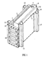
- the apparatus generally comprises a plurality of combustion plates 1 comprising a combustion catalyst, e.g. Pt/ ⁇ -Al 2 O3 , on one surface of the plate, and a plurality of reformer plates 3 comprising a reforming catalyst, e.g. Cu/ZnO/Al 2 O 3 , arranged on one surface of the plate; the plates being arranged in a stack such that the reformer plates and combustion plates alternate.
- a combustion catalyst e.g. Pt/ ⁇ -Al 2 O3
- reformer plates 3 comprising a reforming catalyst, e.g. Cu/ZnO/Al 2 O 3
- the plates may be seen in greater detail in Figs. 2 and 4 .
- the plates are provided with internal manifolds 25,33 which allow passage of gas through the apparatus.
- the apparatus is provided with a number of external manifolds to supply gases to the plates.
- There is an air/combustible fuel mixer 5 provided with an inlet 7 for air and an inlet 9 for combustible fuel e.g. from the outlet of a fuel cell.
- the fuel mixer 5 is connected to a combustible fuel inlet manifold 11 which is in gaseous communication with the internal manifolds 33 of the combustion plates (not shown) and therefore able to provide an air / combustible fuel mixture to the combustion catalyst.
- An exhaust manifold 13 is provided for exhausting the combustion products from the apparatus.
- a reformer inlet manifold 15 is provided on the opposite side of the apparatus to the combustible fuel manifold 11.
- the reformer inlet manifold 15 is in gaseous communication with the internal manifolds 25 of the reformer plates and is able to provide a supply of methanol and water to the reformer catalyst.
- An reformate outlet manifold 17 is also in gaseous communication with the reformer catalyst to allow the reformed gases to exit.
- Two further oil manifolds 19 are provided at opposite sides of the apparatus at the ends of the reformer and combustion plates 1,3.
- the oil manifolds 19 are in fluid communication with tubes 29 running along the length of the plates (see Fig 3 ).
- the oil manifolds 19 and the tubes 29 running along the length of the plates together form a continuous circuit from an oil inlet 21 to an oil outlet 23.
- the apparatus shown could for example be made of aluminium with polymer seals. It will typically be of the order of a few hundred millimetres in size making it suitable for use on an automobile.
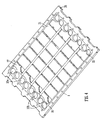
- a reformer plate 3 is shown in Fig. 2 .
- the reformer plate is provided with catalytic material 27 on one plate surface.
- the catalyst is preferably in the form of pellets.
- the reformer plate is provided with rows of internal manifolds 25 along opposite ends of the plate.
- Fig. 3 shows part of the reformer plate in more detail.
- the reformer plate is provided with two different types of internal manifold.
- the first group of manifolds 25a are in gaseous communication with the combustible fuel mixer 5 and the corresponding inlet and exhaust manifolds 11, 13.
- a raised wall 28 on the reformer plate prevents the combustible fuel and air mixture from coming into contact with the surface of the reformer plate on which the reformer catalyst 27 is provided.
- a second group of internal manifolds 25b are in gaseous communication with the reformer external inlet and outlet manifolds 15 and 17.
- the second groups of manifolds 25b do not have a raised wall which means gas flowing between the inlet and outlet manifolds 15, 17 passes over the reformer catalyst 27.
- the reformer plates 3 also have a plurality of oil tubes 29 extending along the length of the plate. When the apparatus is assembled, the oil tubes 29 tubes are connected at both ends to the external oil manifolds 19.
- a combustion plate 1 is shown in Fig. 4 .
- a plurality of combustion catalyst structures 31 are arranged on one surface of the plate.
- the combustion plate is also provided with rows of internal manifolds at each end of the plate arranged into and two different types 33a, 33b.
- the first group of manifolds 33a are in gaseous communication with the combustion inlet/exhaust manifolds 11, 13 which means that the mixed combustible fuel and air passes over the combustion catalyst on the combustion plate 1.
- the gases produced by the combustion reaction can be removed via the exhaust manifold 13.
- the second group of internal manifolds 33b are in gaseous communication with the reformer inlet and outlet manifolds 15, 17.
- a raised wall 35 prevents the flow of reformer feedstock and reformer product stream from coming into contact with the combustion catalyst 31.
- the combustion plate 1 further comprises flame arrests 37 adjacent to the manifolds 33a,b.
- the combustion plate 1 also comprises oil tubes 39 that run along the length of the plate and which are connected to the external oil manifolds 19 when the apparatus is assembled.
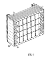
- Fig. 5 shows alternating combustion plates 1 and reformer plates 3 arranged in a stack, with a reformer plate 3 shown outermost.
- the plates 1,3 are stacked such that the catalytic surface of each plate 27, 31 faces the non-catalytic surface of the next plate, which means that the reforming catalyst and the combustion catalyst are not in fluid communication.
- the internal manifolds 25a and 33a align and the internal manifolds 25b and 33b align to provide two separate routes for gas flow through the apparatus.
- One route allows gas to flow from the fuel mixer, through the combustible fuel inlet manifold 11, over the combustion catalyst 31 on the surface of the combustion plates 1 and to exit at the exhaust manifold 13.
- the other, separate, route allows gases for reforming to travel from the inlet manifold 15, over the reformer catalyst 27 on the surface of the reformer plates 3 and to exit at the reformate outlet manifold 17.
- the gases in the two separate routes do not mix.
- the ends of the fluid tubes 29 and 39 can be seen on the end of the stacked assembly in Fig. 5 .
- Fig. 6 shows the general structure of the external gas manifolds 11, 13, 15 and 17. Each manifold is connected to the stack of plates such that holes 43 are in communication with alternate internal manifolds on the plate.
- the external oil manifold 19 is shown in Fig. 7 .
- Oil entering the inlet 45 can travel to holes 47 and vice versa.
- holes 47 are connected to the ends of the oil tubes 29 and 39 such that the oil, manifolds 19 and oil tubes 29 and 39 form a circuit.
- a vaporiser is provided (not shown).
- the vaporiser unit may be in thermal communication with the fluid circuit formed by external manifolds 19 and tubes 29 and 39.
- a mixture of methanol and water is vaporised in the vaporiser unit.
- the integrated apparatus provides the heat necessary to vaporise the fuel and water in this vaporiser unit.
- the vaporised mixture of water and fuel is then provided to manifold 15.
- the reformer product stream comprising hydrogen then exits the stack of plates via the tubes formed by the internal the manifolds 25b and 35b on the opposite side of the reformer plate 3 and exits the apparatus via the external outlet manifold 17. Hydrogen produced by the reforming reaction and exiting the apparatus via the external manifold 17 may be fed into a hydrogen powered fuel cell.
- combustible hydrogen-rich fuel from the outlet of a fuel cell (not shown) is introduced to the mixer inlet 9 whilst air is drawn in via the inlet 7.
- the fuel and air is mixed in the fuel mixer 5 and directed to the external combustible fuel manifold 11.
- the fuel and air mixture flows through the tubes formed by the alignment of internal manifolds 25a and 33a.
- the gas then flows over the surface of the combustion plates 1 and thus the combustion catalyst 31, where combustion takes place.
- the gas flows over all of the combustion plates 1 in parallel.
- the combustion product stream flows out of the apparatus via the tube formed by the internal manifolds 25a and 33a on the opposite side of the plates 1 to the inlet, and then out via the exhaust manifold 13.
- oil is circulated through the oil circuit formed by external manifolds 19 and the tubes 29 and 39.
- the temperature of the oil is chosen such that the reaction temperatures can be controlled.
- Close control of the reaction temperatures can be achieved either by maintaining the fluid at a constant temperature and varying the flow rate of the fluid through the circuit, or by maintaining a constant flow rate through the circuit and varying the fluid temperature.
- the apparatus of the invention can also be used for reforming reactions using alternative fuels such as methane, natural gas or diesel.
- alternative fuels such as methane, natural gas or diesel.
- the temperature of the reforming reaction is higher than the temperature of the methanol reforming reaction.
- the apparatus shown could therefore be made of steel, for example, or any other material that is suitable for use at higher temperature.
- a fluid suitable for use in the additional circuit would be potassium, but any other fluid suitable for use at higher temperatures could be used instead.
Landscapes
- Chemical & Material Sciences (AREA)
- Engineering & Computer Science (AREA)
- Chemical Kinetics & Catalysis (AREA)
- General Chemical & Material Sciences (AREA)
- Sustainable Energy (AREA)
- Sustainable Development (AREA)
- Manufacturing & Machinery (AREA)
- Electrochemistry (AREA)
- Life Sciences & Earth Sciences (AREA)
- Combustion & Propulsion (AREA)
- Organic Chemistry (AREA)
- General Health & Medical Sciences (AREA)
- Inorganic Chemistry (AREA)
- Health & Medical Sciences (AREA)
- Hydrogen, Water And Hydrids (AREA)
- Fuel Cell (AREA)
- Electrical Discharge Machining, Electrochemical Machining, And Combined Machining (AREA)
- Organic Low-Molecular-Weight Compounds And Preparation Thereof (AREA)
Claims (40)
- Dispositif intégré de reformage et de combustion pour une utilisation dans un système de pile à combustible, ledit dispositif comportant une unité de reformage au niveau de laquelle, en utilisation, une réaction de reformage peut avoir lieu en communication thermique avec une unité de combustion au niveau de laquelle, en utilisation, une réaction de combustion peut avoir lieu, caractérisé en ce que ledit dispositif comporte un circuit de fluide supplémentaire (19, 29, 39) en communication thermique à la fois avec ladite unité de reformage et ladite unité de combustion de manière à permettre une commande de la température desdites unités par la circulation d'un fluide ayant une température et/ou un débit présélectionné à travers le circuit de fluide supplémentaire.
- Dispositif tel que revendiqué dans la revendication 1, comportant au moins une plaque de reformage (3) sur laquelle, en utilisation, une réaction de reformage peut avoir lieu, et au moins une plaque de combustion (1) sur laquelle, en utilisation, une réaction de combustion peut avoir lieu, lesdites plaques étant agencées dans une pile de telle sorte que les plaques de reformage (3) et les plaques de combustion (1) sont intercalées, dans lequel le dispositif est agencé de telle sorte que, en utilisation, une réaction de reformage et une réaction de combustion peuvent avoir lieu simultanément, ladite réaction de combustion fournissant de la chaleur pour la réaction de reformage.
- Dispositif tel que revendiqué dans la revendication 2, dans lequel le circuit de fluide supplémentaire (19, 29, 39) comporte au moins un tube (29, 39) qui s'étend le long d'au moins une partie de la longueur d'au moins une plaque (3, 1).
- Dispositif tel que revendiqué dans la revendication 3, dans lequel le circuit de fluide supplémentaire (19, 29, 39) comporte des tubes (29, 39) qui s'étendent le long d'au moins une partie de la longueur d'au moins une plaque de combustion (1) et d'au moins une plaque de reformage (3).
- Dispositif tel que revendiqué dans la revendication 4, dans lequel chaque plaque (3, 1) comporte au moins un tube (29, 39) qui forme une partie du circuit de fluide supplémentaire (19, 29, 39).
- Dispositif tel que revendiqué dans l'une quelconque des revendications 1 à 5, dans lequel le circuit de fluide supplémentaire (19, 29, 39) comporte au moins un conduit comportant une surface de transfert thermique en communication thermique avec la paroi intérieure du conduit.
- Dispositif tel que revendiqué dans la revendication 6, dans lequel ladite surface de transfert thermique comporte une ou plusieurs nervures s'étendant à travers l'intérieur du conduit.
- Dispositif tel que revendiqué dans l'une quelconque des revendications 1 à 7, comportant en outre une unité de gestion thermique intégrée dans ledit circuit de fluide supplémentaire (19, 29, 39).
- Dispositif tel que revendiqué dans l'une quelconque des revendications 2 à 8, dans lequel les plaques de reformage (3) et les plaques de combustion (1) sont alternées.
- Dispositif tel que revendiqué dans l'une quelconque des revendications 2 à 9, adapté pour délivrer un flux de gaz à travers le dispositif et en contact avec les plaques de reformage (3), et un flux de gaz à travers le dispositif et en contact avec les plaques de combustion (1), dans lequel les flux sont en communication thermique mais pas en communication fluidique.
- Dispositif tel que revendiqué dans la revendication 10, dans lequel le dispositif est adapté pour permettre aux flux de gaz de s'écouler dans des directions opposées à travers le dispositif de telle sorte qu'un échange de chaleur entre la réaction de combustion et la réaction de reformage peut se produire.
- Dispositif tel que revendiqué dans la revendication 10 ou 11, dans lequel les plaques de reformage (3) et les plaques de combustion (1) comportent des collecteurs internes (25, 33) de telle sorte que lorsque les plaques sont assemblées dans une pile, les collecteurs sont agencés de manière à guider les gaz au-dessus des plaques.
- Dispositif tel que revendiqué dans l'une quelconque des revendications 2 à 12, dans lequel la plaque de combustion (1) comporte un catalyseur de combustion en céramique (31).
- Dispositif tel que revendiqué dans la revendication 13, dans lequel le catalyseur de combustion (31) est agencé sur une surface de la plaque de combustion (1).
- Dispositif tel que revendiqué dans la revendication 13 ou 14, dans lequel la plaque de combustion (1) comporte de multiples fragments de catalyseur en céramique.
- Dispositif tel que revendiqué dans l'une quelconque des revendications 2 à 15, dans lequel la plaque de reformage (3) comporte un catalyseur de reformage (27).
- Dispositif tel que revendiqué dans la revendication 16, dans lequel ledit catalyseur de reformage (27) est adapté pour catalyser la réaction d'un combustible et d'eau pour produire de l'hydrogène.
- Dispositif tel que revendiqué dans la revendication 16 ou 17, dans lequel le catalyseur de reformage (27) est agencé sur une surface de la plaque de reformage (3).
- Dispositif tel que revendiqué dans l'une quelconque des revendications 2 à 18, comportant un catalyseur de combustion (31) et un catalyseur de reformage (27), lesdits catalyseurs n'étant pas en communication fluidique.
- Dispositif tel que revendiqué dans l'une quelconque des revendications 2 à 19, dans lequel les plaques de combustion (1) comportent des moyens (37) d'arrêt de flammes situés au niveau de l'entrée de gaz (33a, 33b).
- Système de pile à combustible comportant un dispositif intégré de reformage et de combustion tel que revendiqué dans l'une quelconque des revendications 1 à 20 et une pile à combustible.
- Système de pile à combustible tel que revendiqué dans la revendication 21, dans lequel ledit circuit de fluide supplémentaire (19, 29, 39) est thermiquement intégré dans ladite pile à combustible.
- Procédé pour préparer de l'hydrogène à partir de combustible et d'eau en utilisant le dispositif tel que revendiqué dans l'une quelconque des revendications 1 à 20, ledit procédé comportant les étapes consistant à : faire passer une charge de reformage comportant un combustible et de l'eau à travers l'unité de reformage de telle sorte qu'une réaction de reformage ait lieu pour produire un flux de produit de reformage comportant de l'hydrogène, et faire passer simultanément une charge de combustible à travers l'unité de combustion de telle sorte qu'une combustion ait lieu pour produire un flux de produit de combustion, de telle sorte que la réaction de combustion produise de la chaleur pour la réaction de reformage.
- Procédé tel que revendiqué dans la revendication 23, dans lequel le flux de gaz comportant la charge de reformage et le flux de produit de reformage sont en communication thermique mais pas en communication fluidique avec le flux de gaz comportant la charge de combustion et le flux de produit de combustion.
- Procédé tel que revendiqué dans la revendication 23 ou 24, comportant en outre l'étape consistant à commander la température en faisant circuler un fluide à travers ledit circuit de fluide supplémentaire (19, 29, 39).
- Procédé tel que revendiqué dans l'une quelconque des revendications 23 à 25, dans lequel le dispositif comporte au moins une plaque de reformage (3) et au moins une plaque de combustion (1) agencées dans une pile de telle sorte que les plaques de reformage (3) et les plaques de combustion (1) sont intercalées, ledit circuit de fluide supplémentaire (19, 29, 39) étant en communication thermique avec au moins une parmi ladite plaque de reformage et ladite plaque de combustion ; ledit procédé comportant en outre l'étape consistant à faire circuler un fluide à travers ledit circuit de fluide supplémentaire (19, 29, 39) de manière à pouvoir commander la température du système.
- Procédé tel que revendiqué dans l'une quelconque des revendications 23 à 26, dans lequel lesdits flux de gaz se déplacent à travers le dispositif dans des directions opposées.
- Procédé tel que revendiqué dans l'une quelconque des revendications 23 à 27, dans lequel le combustible pour la réaction de reformage comporte du méthanol.
- Procédé tel que revendiqué dans la revendication 28, dans lequel la réaction de reformage a lieu à une température entre 150 °C et 250 °C, de manière plus préférée de 180 à 200 °C.
- Procédé tel que revendiqué dans la revendication 29, dans lequel la réaction de combustion a lieu entre 150 °C et 300 °C, de manière plus préférée de 200 à 250 °C.
- Procédé tel que revendiqué dans la revendication 28, dans lequel le fluide ayant circulé à travers ledit circuit de fluide supplémentaire (19, 29, 39) a une température entre 150 et 250 °C, de manière plus préférée de 180 à 200 °C.
- Procédé tel que revendiqué dans la revendication 31, dans lequel ledit fluide comporte de l'huile.
- Procédé tel que revendiqué dans l'une quelconque des revendications 23 à 27, dans lequel le combustible pour la réaction de reformage comporte au moins un élément parmi du méthane, du gaz naturel ou du gazole.
- Procédé tel que revendiqué dans la revendication 33, dans lequel la température de la réaction de reformage se situe entre 350 °C et 850 °C, de manière plus préférée de 500 °C à 700 °C.
- Procédé tel que revendiqué dans la revendication 34, dans lequel la température de la réaction de combustion se situe entre 400 °C et 900 °C, de manière plus préférée de 550 °C à 750 °C.
- Procédé tel que revendiqué dans l'une quelconque des revendications 33 à 35, dans lequel le fluide ayant circulé à travers ledit circuit de fluide supplémentaire (19, 29, 39) a une température entre 500 °C et 700 °C.
- Procédé tel que revendiqué dans la revendication 36, dans lequel ledit fluide comporte du potassium.
- Procédé tel que revendiqué dans l'une quelconque des revendications 23 à 37, comportant l'étape consistant à fournir le flux de produit de reformage à une pile à combustible à hydrogène.
- Procédé tel que revendiqué dans l'une quelconque des revendications 23 à 38, comportant l'étape consistant à fournir la charge de combustion à partir du sous-produit d'une pile à combustible à hydrogène.
- Procédé tel que revendiqué dans la revendication 39, dans lequel ledit sous-produit comporte au moins un élément parmi l'hydrogène, des hydrocarbures, le méthanol et le monoxyde de carbone.
Applications Claiming Priority (2)
| Application Number | Priority Date | Filing Date | Title |
|---|---|---|---|
| GBGB0509670.6A GB0509670D0 (en) | 2005-05-11 | 2005-05-11 | Fuel processing system |
| PCT/GB2006/001727 WO2006120450A1 (fr) | 2005-05-11 | 2006-05-11 | Systeme de traitement de combustible |
Publications (2)
| Publication Number | Publication Date |
|---|---|
| EP1886372A1 EP1886372A1 (fr) | 2008-02-13 |
| EP1886372B1 true EP1886372B1 (fr) | 2011-01-26 |
Family
ID=34685480
Family Applications (1)
| Application Number | Title | Priority Date | Filing Date |
|---|---|---|---|
| EP06727078A Not-in-force EP1886372B1 (fr) | 2005-05-11 | 2006-05-11 | Systeme de traitement de combustible |
Country Status (8)
| Country | Link |
|---|---|
| US (1) | US8992642B2 (fr) |
| EP (1) | EP1886372B1 (fr) |
| AT (1) | ATE497265T1 (fr) |
| DE (1) | DE602006019857D1 (fr) |
| DK (1) | DK1886372T3 (fr) |
| ES (1) | ES2358214T3 (fr) |
| GB (1) | GB0509670D0 (fr) |
| WO (1) | WO2006120450A1 (fr) |
Families Citing this family (5)
| Publication number | Priority date | Publication date | Assignee | Title |
|---|---|---|---|---|
| CN103047645B (zh) * | 2012-12-25 | 2017-02-08 | 管理 | 一种Mg催化水基助燃煤、气、油低碳硫硝排放的锅窑炉 |
| EA039539B1 (ru) | 2016-11-09 | 2022-02-08 | 8 Риверз Кэпитл, Ллк | Способ выработки энергии с интегрированным производством водорода |
| CN111526935A (zh) | 2017-11-09 | 2020-08-11 | 八河流资产有限责任公司 | 用于生产和分离氢气和二氧化碳的系统和方法 |
| US11859517B2 (en) | 2019-06-13 | 2024-01-02 | 8 Rivers Capital, Llc | Power production with cogeneration of further products |
| KR20240101705A (ko) | 2021-11-18 | 2024-07-02 | 8 리버스 캐피탈, 엘엘씨 | 수소 생산 방법 |
Family Cites Families (17)
| Publication number | Priority date | Publication date | Assignee | Title |
|---|---|---|---|---|
| US4902484A (en) * | 1985-07-18 | 1990-02-20 | John Zink Company | Oxygen injector means for secondary reformer |
| JPH085644B2 (ja) * | 1989-11-27 | 1996-01-24 | 石川島播磨重工業株式会社 | プレート型改質器 |
| EP0687648B1 (fr) * | 1994-06-15 | 1998-09-16 | dbb fuel cell engines GmbH | Réformage de méthanol en deux étapes |
| JPH0812303A (ja) * | 1994-07-05 | 1996-01-16 | Ishikawajima Harima Heavy Ind Co Ltd | プレートリフォーマ |
| US5858314A (en) * | 1996-04-12 | 1999-01-12 | Ztek Corporation | Thermally enhanced compact reformer |
| DE19639150C2 (de) * | 1996-09-24 | 1998-07-02 | Daimler Benz Ag | Zentrale Heizvorrichtung für ein Gaserzeugungssystem |
| JP3129670B2 (ja) * | 1997-02-28 | 2001-01-31 | 三菱電機株式会社 | 燃料改質装置 |
| JPH10265202A (ja) * | 1997-03-25 | 1998-10-06 | Ishikawajima Harima Heavy Ind Co Ltd | 水素製造装置 |
| DE19754012C2 (de) * | 1997-12-05 | 1999-11-11 | Dbb Fuel Cell Engines Gmbh | Anlage zur Wasserdampfreformierung eines Kohlenwasserstoffs |
| DE19926608B4 (de) * | 1999-06-11 | 2004-10-14 | Ballard Power Systems Ag | Chemischer Reaktor für ein Brennstoffzellensystem |
| DE10007764A1 (de) * | 2000-02-20 | 2001-08-23 | Gen Motors Corp | Brennerelement |
| US20020071797A1 (en) * | 2000-10-06 | 2002-06-13 | Loffler Daniel G. | Catalytic separator plate reactor and method of catalytic reforming of fuel to hydrogen |
| US7179313B2 (en) * | 2002-08-02 | 2007-02-20 | Catacel Corp. | Regenerative autothermal catalytic steam reformer |
| US7678346B2 (en) * | 2003-01-30 | 2010-03-16 | Gm Global Technology Operations, Inc. | Dual function CO clean-up/sorber unit |
| US20050186455A1 (en) * | 2003-06-27 | 2005-08-25 | Ultracell Corporation, A California Corporation | Micro fuel cell system start up and shut down systems and methods |
| EP1517389B1 (fr) * | 2003-09-15 | 2006-08-02 | Balcke-Dürr GmbH | Unité de reformage pour batterie de piles à combustible transformant un gaz de hydrocarbure d'alimentation en un gaz combustible contenant de l'hydrogène |
| US20070000173A1 (en) * | 2005-06-28 | 2007-01-04 | Michael Boe | Compact reforming reactor |
-
2005
- 2005-05-11 GB GBGB0509670.6A patent/GB0509670D0/en not_active Ceased
-
2006
- 2006-05-11 DK DK06727078.5T patent/DK1886372T3/da active
- 2006-05-11 WO PCT/GB2006/001727 patent/WO2006120450A1/fr active Application Filing
- 2006-05-11 ES ES06727078T patent/ES2358214T3/es active Active
- 2006-05-11 DE DE602006019857T patent/DE602006019857D1/de active Active
- 2006-05-11 AT AT06727078T patent/ATE497265T1/de not_active IP Right Cessation
- 2006-05-11 US US11/920,138 patent/US8992642B2/en not_active Expired - Fee Related
- 2006-05-11 EP EP06727078A patent/EP1886372B1/fr not_active Not-in-force
Also Published As
| Publication number | Publication date |
|---|---|
| EP1886372A1 (fr) | 2008-02-13 |
| ES2358214T3 (es) | 2011-05-06 |
| GB0509670D0 (en) | 2005-06-15 |
| US8992642B2 (en) | 2015-03-31 |
| DE602006019857D1 (de) | 2011-03-10 |
| ATE497265T1 (de) | 2011-02-15 |
| DK1886372T3 (da) | 2011-04-18 |
| US20090104483A1 (en) | 2009-04-23 |
| WO2006120450A1 (fr) | 2006-11-16 |
Similar Documents
| Publication | Publication Date | Title |
|---|---|---|
| EP1345679B1 (fr) | Module de reacteur s'utilisant dans un dispositif compact de traitement de combustible | |
| US6245303B1 (en) | Reactor for producing hydrogen from hydrocarbon fuels | |
| JP3129670B2 (ja) | 燃料改質装置 | |
| US6096286A (en) | System for steam reformation of a hydrocarbon and operating method therefor | |
| JP5015590B2 (ja) | 燃料改質反応物の迅速加熱用の方法および装置 | |
| US20010018140A1 (en) | Catalytic burner element inside a fuel cell with structured catalytic coated surfaces | |
| US20100133474A1 (en) | Thermally coupled monolith reactor | |
| AU2002236584A1 (en) | Reactor module for use in a compact fuel processor | |
| CN104528644A (zh) | 转化器装置和方法 | |
| CA2862538A1 (fr) | Processeur de combustible chauffe catalytiquement a supports structures remplacables portant un catalyseur pour pile a combustible | |
| EP1886372B1 (fr) | Systeme de traitement de combustible | |
| WO2007122497A3 (fr) | Unite de reformage d'un echangeur de chaleur et systeme de reformage | |
| US20020131919A1 (en) | Modular fuel processing system for plate reforming type units | |
| US7497881B2 (en) | Heat exchanger mechanization to transfer reformate energy to steam and air | |
| CN112151831B (zh) | 重整器及其燃料电池发电系统 | |
| JP5163147B2 (ja) | 熱交換器及び複合型燃料反応器 | |
| US8263027B2 (en) | Apparatus, systems and methods for the production of hydrogen | |
| US6896986B2 (en) | Multi-stage rapid vaporization apparatus and method | |
| EP2719447B1 (fr) | Appareil combiné d'échange de chaleur et de mélange de fluides | |
| US20020106596A1 (en) | Catalytic burner element inside a fuel cell with structured catalytic coated surfaces | |
| KR20000005383A (ko) | 열 강화된 소형 개질기 | |
| JP2000159502A (ja) | 改質装置及びその改質装置を用いた燃料電池発電装置 | |
| KR20150102835A (ko) | 스텍 연료의 전후 처리 및 열교환을 위한 통합 장치 및 그 운전 방법 | |
| KR100979572B1 (ko) | 연료 개질 시스템 | |
| WO2012105922A2 (fr) | Reformeur autothermique hybride à mousse/basse pression |
Legal Events
| Date | Code | Title | Description |
|---|---|---|---|
| PUAI | Public reference made under article 153(3) epc to a published international application that has entered the european phase |
Free format text: ORIGINAL CODE: 0009012 |
|
| 17P | Request for examination filed |
Effective date: 20071211 |
|
| AK | Designated contracting states |
Kind code of ref document: A1 Designated state(s): AT BE BG CH CY CZ DE DK EE ES FI FR GB GR HU IE IS IT LI LT LU LV MC NL PL PT RO SE SI SK TR |
|
| 17Q | First examination report despatched |
Effective date: 20080519 |
|
| DAX | Request for extension of the european patent (deleted) | ||
| GRAP | Despatch of communication of intention to grant a patent |
Free format text: ORIGINAL CODE: EPIDOSNIGR1 |
|
| GRAS | Grant fee paid |
Free format text: ORIGINAL CODE: EPIDOSNIGR3 |
|
| GRAA | (expected) grant |
Free format text: ORIGINAL CODE: 0009210 |
|
| AK | Designated contracting states |
Kind code of ref document: B1 Designated state(s): AT BE BG CH CY CZ DE DK EE ES FI FR GB GR HU IE IS IT LI LT LU LV MC NL PL PT RO SE SI SK TR |
|
| REG | Reference to a national code |
Ref country code: GB Ref legal event code: FG4D |
|
| REG | Reference to a national code |
Ref country code: CH Ref legal event code: EP |
|
| REG | Reference to a national code |
Ref country code: IE Ref legal event code: FG4D |
|
| REF | Corresponds to: |
Ref document number: 602006019857 Country of ref document: DE Date of ref document: 20110310 Kind code of ref document: P |
|
| REG | Reference to a national code |
Ref country code: DE Ref legal event code: R096 Ref document number: 602006019857 Country of ref document: DE Effective date: 20110310 |
|
| REG | Reference to a national code |
Ref country code: DK Ref legal event code: T3 |
|
| REG | Reference to a national code |
Ref country code: NL Ref legal event code: T3 |
|
| REG | Reference to a national code |
Ref country code: ES Ref legal event code: FG2A Ref document number: 2358214 Country of ref document: ES Kind code of ref document: T3 Effective date: 20110425 |
|
| REG | Reference to a national code |
Ref country code: SE Ref legal event code: TRGR |
|
| LTIE | Lt: invalidation of european patent or patent extension |
Effective date: 20110126 |
|
| PG25 | Lapsed in a contracting state [announced via postgrant information from national office to epo] |
Ref country code: IS Free format text: LAPSE BECAUSE OF FAILURE TO SUBMIT A TRANSLATION OF THE DESCRIPTION OR TO PAY THE FEE WITHIN THE PRESCRIBED TIME-LIMIT Effective date: 20110526 Ref country code: GR Free format text: LAPSE BECAUSE OF FAILURE TO SUBMIT A TRANSLATION OF THE DESCRIPTION OR TO PAY THE FEE WITHIN THE PRESCRIBED TIME-LIMIT Effective date: 20110427 Ref country code: PT Free format text: LAPSE BECAUSE OF FAILURE TO SUBMIT A TRANSLATION OF THE DESCRIPTION OR TO PAY THE FEE WITHIN THE PRESCRIBED TIME-LIMIT Effective date: 20110526 Ref country code: LV Free format text: LAPSE BECAUSE OF FAILURE TO SUBMIT A TRANSLATION OF THE DESCRIPTION OR TO PAY THE FEE WITHIN THE PRESCRIBED TIME-LIMIT Effective date: 20110126 Ref country code: LT Free format text: LAPSE BECAUSE OF FAILURE TO SUBMIT A TRANSLATION OF THE DESCRIPTION OR TO PAY THE FEE WITHIN THE PRESCRIBED TIME-LIMIT Effective date: 20110126 |
|
| PG25 | Lapsed in a contracting state [announced via postgrant information from national office to epo] |
Ref country code: SI Free format text: LAPSE BECAUSE OF FAILURE TO SUBMIT A TRANSLATION OF THE DESCRIPTION OR TO PAY THE FEE WITHIN THE PRESCRIBED TIME-LIMIT Effective date: 20110126 Ref country code: AT Free format text: LAPSE BECAUSE OF FAILURE TO SUBMIT A TRANSLATION OF THE DESCRIPTION OR TO PAY THE FEE WITHIN THE PRESCRIBED TIME-LIMIT Effective date: 20110126 Ref country code: BE Free format text: LAPSE BECAUSE OF FAILURE TO SUBMIT A TRANSLATION OF THE DESCRIPTION OR TO PAY THE FEE WITHIN THE PRESCRIBED TIME-LIMIT Effective date: 20110126 Ref country code: CY Free format text: LAPSE BECAUSE OF FAILURE TO SUBMIT A TRANSLATION OF THE DESCRIPTION OR TO PAY THE FEE WITHIN THE PRESCRIBED TIME-LIMIT Effective date: 20110126 Ref country code: BG Free format text: LAPSE BECAUSE OF FAILURE TO SUBMIT A TRANSLATION OF THE DESCRIPTION OR TO PAY THE FEE WITHIN THE PRESCRIBED TIME-LIMIT Effective date: 20110426 Ref country code: FI Free format text: LAPSE BECAUSE OF FAILURE TO SUBMIT A TRANSLATION OF THE DESCRIPTION OR TO PAY THE FEE WITHIN THE PRESCRIBED TIME-LIMIT Effective date: 20110126 Ref country code: PL Free format text: LAPSE BECAUSE OF FAILURE TO SUBMIT A TRANSLATION OF THE DESCRIPTION OR TO PAY THE FEE WITHIN THE PRESCRIBED TIME-LIMIT Effective date: 20110126 |
|
| PG25 | Lapsed in a contracting state [announced via postgrant information from national office to epo] |
Ref country code: EE Free format text: LAPSE BECAUSE OF FAILURE TO SUBMIT A TRANSLATION OF THE DESCRIPTION OR TO PAY THE FEE WITHIN THE PRESCRIBED TIME-LIMIT Effective date: 20110126 |
|
| PG25 | Lapsed in a contracting state [announced via postgrant information from national office to epo] |
Ref country code: CZ Free format text: LAPSE BECAUSE OF FAILURE TO SUBMIT A TRANSLATION OF THE DESCRIPTION OR TO PAY THE FEE WITHIN THE PRESCRIBED TIME-LIMIT Effective date: 20110126 Ref country code: RO Free format text: LAPSE BECAUSE OF FAILURE TO SUBMIT A TRANSLATION OF THE DESCRIPTION OR TO PAY THE FEE WITHIN THE PRESCRIBED TIME-LIMIT Effective date: 20110126 Ref country code: SK Free format text: LAPSE BECAUSE OF FAILURE TO SUBMIT A TRANSLATION OF THE DESCRIPTION OR TO PAY THE FEE WITHIN THE PRESCRIBED TIME-LIMIT Effective date: 20110126 |
|
| PLBE | No opposition filed within time limit |
Free format text: ORIGINAL CODE: 0009261 |
|
| STAA | Information on the status of an ep patent application or granted ep patent |
Free format text: STATUS: NO OPPOSITION FILED WITHIN TIME LIMIT |
|
| PG25 | Lapsed in a contracting state [announced via postgrant information from national office to epo] |
Ref country code: MC Free format text: LAPSE BECAUSE OF NON-PAYMENT OF DUE FEES Effective date: 20110531 |
|
| REG | Reference to a national code |
Ref country code: CH Ref legal event code: PL |
|
| 26N | No opposition filed |
Effective date: 20111027 |
|
| PG25 | Lapsed in a contracting state [announced via postgrant information from national office to epo] |
Ref country code: LI Free format text: LAPSE BECAUSE OF NON-PAYMENT OF DUE FEES Effective date: 20110531 Ref country code: CH Free format text: LAPSE BECAUSE OF NON-PAYMENT OF DUE FEES Effective date: 20110531 |
|
| REG | Reference to a national code |
Ref country code: DE Ref legal event code: R097 Ref document number: 602006019857 Country of ref document: DE Effective date: 20111027 |
|
| REG | Reference to a national code |
Ref country code: IE Ref legal event code: MM4A |
|
| PG25 | Lapsed in a contracting state [announced via postgrant information from national office to epo] |
Ref country code: IE Free format text: LAPSE BECAUSE OF NON-PAYMENT OF DUE FEES Effective date: 20110511 |
|
| PG25 | Lapsed in a contracting state [announced via postgrant information from national office to epo] |
Ref country code: LU Free format text: LAPSE BECAUSE OF NON-PAYMENT OF DUE FEES Effective date: 20110511 |
|
| PG25 | Lapsed in a contracting state [announced via postgrant information from national office to epo] |
Ref country code: TR Free format text: LAPSE BECAUSE OF FAILURE TO SUBMIT A TRANSLATION OF THE DESCRIPTION OR TO PAY THE FEE WITHIN THE PRESCRIBED TIME-LIMIT Effective date: 20110126 |
|
| PG25 | Lapsed in a contracting state [announced via postgrant information from national office to epo] |
Ref country code: HU Free format text: LAPSE BECAUSE OF FAILURE TO SUBMIT A TRANSLATION OF THE DESCRIPTION OR TO PAY THE FEE WITHIN THE PRESCRIBED TIME-LIMIT Effective date: 20110126 |
|
| REG | Reference to a national code |
Ref country code: FR Ref legal event code: PLFP Year of fee payment: 11 |
|
| REG | Reference to a national code |
Ref country code: FR Ref legal event code: PLFP Year of fee payment: 12 |
|
| REG | Reference to a national code |
Ref country code: DE Ref legal event code: R082 Ref document number: 602006019857 Country of ref document: DE Representative=s name: DEHNSGERMANY PARTNERSCHAFT VON PATENTANWAELTEN, DE |
|
| PGFP | Annual fee paid to national office [announced via postgrant information from national office to epo] |
Ref country code: NL Payment date: 20210820 Year of fee payment: 16 |
|
| PGFP | Annual fee paid to national office [announced via postgrant information from national office to epo] |
Ref country code: IT Payment date: 20210730 Year of fee payment: 16 Ref country code: FR Payment date: 20210730 Year of fee payment: 16 |
|
| PGFP | Annual fee paid to national office [announced via postgrant information from national office to epo] |
Ref country code: DE Payment date: 20210802 Year of fee payment: 16 Ref country code: ES Payment date: 20210810 Year of fee payment: 16 Ref country code: DK Payment date: 20210730 Year of fee payment: 16 Ref country code: GB Payment date: 20210729 Year of fee payment: 16 Ref country code: SE Payment date: 20210730 Year of fee payment: 16 |
|
| REG | Reference to a national code |
Ref country code: DE Ref legal event code: R119 Ref document number: 602006019857 Country of ref document: DE |
|
| REG | Reference to a national code |
Ref country code: DK Ref legal event code: EBP Effective date: 20220531 |
|
| REG | Reference to a national code |
Ref country code: SE Ref legal event code: EUG |
|
| REG | Reference to a national code |
Ref country code: NL Ref legal event code: MM Effective date: 20220601 |
|
| GBPC | Gb: european patent ceased through non-payment of renewal fee |
Effective date: 20220511 |
|
| PG25 | Lapsed in a contracting state [announced via postgrant information from national office to epo] |
Ref country code: SE Free format text: LAPSE BECAUSE OF NON-PAYMENT OF DUE FEES Effective date: 20220512 |
|
| PG25 | Lapsed in a contracting state [announced via postgrant information from national office to epo] |
Ref country code: FR Free format text: LAPSE BECAUSE OF NON-PAYMENT OF DUE FEES Effective date: 20220531 Ref country code: DK Free format text: LAPSE BECAUSE OF NON-PAYMENT OF DUE FEES Effective date: 20220531 |
|
| PG25 | Lapsed in a contracting state [announced via postgrant information from national office to epo] |
Ref country code: GB Free format text: LAPSE BECAUSE OF NON-PAYMENT OF DUE FEES Effective date: 20220511 Ref country code: DE Free format text: LAPSE BECAUSE OF NON-PAYMENT OF DUE FEES Effective date: 20221201 |
|
| REG | Reference to a national code |
Ref country code: ES Ref legal event code: FD2A Effective date: 20230627 |
|
| PG25 | Lapsed in a contracting state [announced via postgrant information from national office to epo] |
Ref country code: NL Free format text: LAPSE BECAUSE OF NON-PAYMENT OF DUE FEES Effective date: 20220601 |
|
| PG25 | Lapsed in a contracting state [announced via postgrant information from national office to epo] |
Ref country code: IT Free format text: LAPSE BECAUSE OF NON-PAYMENT OF DUE FEES Effective date: 20220511 Ref country code: ES Free format text: LAPSE BECAUSE OF NON-PAYMENT OF DUE FEES Effective date: 20220512 |