EP1886130B1 - Verfahren und vorrichtung zum überwachen einer strömenden flüssigkeit auf das vorhandensein von luft - Google Patents
Verfahren und vorrichtung zum überwachen einer strömenden flüssigkeit auf das vorhandensein von luft Download PDFInfo
- Publication number
- EP1886130B1 EP1886130B1 EP06724358.4A EP06724358A EP1886130B1 EP 1886130 B1 EP1886130 B1 EP 1886130B1 EP 06724358 A EP06724358 A EP 06724358A EP 1886130 B1 EP1886130 B1 EP 1886130B1
- Authority
- EP
- European Patent Office
- Prior art keywords
- signal
- characteristic
- pattern
- sequence
- air
- Prior art date
- Legal status (The legal status is an assumption and is not a legal conclusion. Google has not performed a legal analysis and makes no representation as to the accuracy of the status listed.)
- Expired - Lifetime
Links
Images


Classifications
-
- G—PHYSICS
- G01—MEASURING; TESTING
- G01N—INVESTIGATING OR ANALYSING MATERIALS BY DETERMINING THEIR CHEMICAL OR PHYSICAL PROPERTIES
- G01N29/00—Investigating or analysing materials by the use of ultrasonic, sonic or infrasonic waves; Visualisation of the interior of objects by transmitting ultrasonic or sonic waves through the object
- G01N29/02—Analysing fluids
- G01N29/032—Analysing fluids by measuring attenuation of acoustic waves
-
- A—HUMAN NECESSITIES
- A61—MEDICAL OR VETERINARY SCIENCE; HYGIENE
- A61M—DEVICES FOR INTRODUCING MEDIA INTO, OR ONTO, THE BODY; DEVICES FOR TRANSDUCING BODY MEDIA OR FOR TAKING MEDIA FROM THE BODY; DEVICES FOR PRODUCING OR ENDING SLEEP OR STUPOR
- A61M1/00—Suction or pumping devices for medical purposes; Devices for carrying-off, for treatment of, or for carrying-over, body-liquids; Drainage systems
- A61M1/36—Other treatment of blood in a by-pass of the natural circulatory system, e.g. temperature adaptation, irradiation ; Extra-corporeal blood circuits
- A61M1/3621—Extra-corporeal blood circuits
- A61M1/3626—Gas bubble detectors
-
- G—PHYSICS
- G01—MEASURING; TESTING
- G01N—INVESTIGATING OR ANALYSING MATERIALS BY DETERMINING THEIR CHEMICAL OR PHYSICAL PROPERTIES
- G01N2291/00—Indexing codes associated with group G01N29/00
- G01N2291/02—Indexing codes associated with the analysed material
- G01N2291/024—Mixtures
- G01N2291/02433—Gases in liquids, e.g. bubbles, foams
-
- G—PHYSICS
- G01—MEASURING; TESTING
- G01N—INVESTIGATING OR ANALYSING MATERIALS BY DETERMINING THEIR CHEMICAL OR PHYSICAL PROPERTIES
- G01N2291/00—Indexing codes associated with group G01N29/00
- G01N2291/02—Indexing codes associated with the analysed material
- G01N2291/024—Mixtures
- G01N2291/02466—Biological material, e.g. blood
-
- G—PHYSICS
- G01—MEASURING; TESTING
- G01N—INVESTIGATING OR ANALYSING MATERIALS BY DETERMINING THEIR CHEMICAL OR PHYSICAL PROPERTIES
- G01N2291/00—Indexing codes associated with group G01N29/00
- G01N2291/02—Indexing codes associated with the analysed material
- G01N2291/028—Material parameters
- G01N2291/02854—Length, thickness
Definitions
- the invention relates to a method for monitoring a flowing liquid for the presence of air, in particular the blood flowing in an extracorporeal blood circuit of an extracorporeal blood treatment device, and a method for extracorporeal blood treatment with an extracorporeal blood circulation, wherein the presence of air in the extracorporeal blood circulation is monitored.
- the invention relates to a device for monitoring a flowing liquid, in particular of the blood flowing in an extracorporeal circuit, to the presence of air, and to an apparatus for extracorporeal blood treatment with a device for monitoring the blood flowing in the extracorporeal circuit of the blood treatment device on the Presence of air.
- extracorporeal blood treatment in which the patient's blood flows through a blood treatment unit in an extracorporeal bloodstream.
- One of the major complications of extracorporeal blood treatment, such as hemodialysis or hemofiltration, is the possibility of air entering the extracorporeal blood circulation. The same risk exists not only with extracorporeal blood treatments but also with infusion solutions.
- the known drip chambers For separating entrained air bubbles from blood or infusion solutions serve the known drip chambers, which are arranged in the venous branch of the extracorporeal blood circulation or in the infusion line.
- the known drip chambers catch the bubbles with high security. Nevertheless, there is a general danger that air bubbles will be infused intravenously to the patient.
- DIN / EN 60601-2-16 requires further increasing the safety of air detectors, whose functional reliability requires very high standards.
- the known air detectors are based on the different absorption of ultrasound in liquid and gaseous media and the scattering of ultrasound at interfaces. In addition to the ultrasonic sensors, air detectors are known which are based on the different dielectric constants and the different conductivities of liquid and gaseous media. For the detection of air signal pulses are coupled into the flowing liquid, while the emerging from the flowing liquid signal pulses are received. In this case, the presence of air is then concluded when the received signal falls below one or more fixed reference levels.
- a device for detecting air bubbles in flowing liquids which is based on an ultrasonic measurement with a compensation of environmental influences, is for example from EP 1 182 452 A2 known.
- microbubbles In addition to the relatively large individual bubbles, for example in dialysis treatments, even very small air bubbles, so-called microbubbles, can occur. They typically arise when air can enter the arterial branch of the extracorporeal bloodstream due to leaks.
- the initially relatively large individual bubbles are initially through the blood pump crushed.
- the air bubbles are further comminuted, the larger air bubbles can be deposited in the venous bladder due to their buoyancy, while the microbubbles, in general have a diameter of about 0.2 mm and a volume of about 4nl, can be transported with the blood stream from the bladder and the patient can get.
- the patient's bloodstream then contains microbubbles with a continuous distribution of the diameter of the diameter of about 0.3 mm.
- the extracorporeal blood circulation is usually rinsed with an isotonic saline solution. There is a risk that not flushed air bubbles dissolve during treatment and then can be infused into the patient unrecognized in a "cloud" of microbubbles.
- the US 5,824,881 describes a method for monitoring a flowing medium for the presence of air, in which a series of signal pulses are coupled into the flowing medium and a series of signal pulses are coupled out of the flowing medium. From the decoupled signal a detection signature is determined, which is compared for reasons of redundancy with two reference signatures.
- the reference signature is intended to describe a condition in which air bubbles are not contained in the line. In the event of a deviation from the detection signature and the reference signature, the presence of air bubbles is inferred.
- the invention is therefore based on the object of specifying a method for monitoring a flowing liquid for the presence of air, which also allows the detection of relatively small air bubbles, in particular micro-bubbles for the detection of different incidents with high security.
- Another object of the invention is to provide a method for extracorporeal blood treatment Specify an extracorporeal blood circulation, which can be detected with high certainty and relatively small air bubbles, especially micro-bubbles in the extracorporeal circuit.
- the operating principle of the method and the device according to the invention is based on that a sequence of signal pulses or a continuous signal is coupled into the flowing liquid and the emerging from the flowing liquid signal pulses or the continuous signal are received, wherein from the received signal pulses or the received continuous signal is extracted, a signal pattern that is characteristic of the timing of the received signal pulses or the continuous signal in a predetermined time interval.
- This characteristic signal pattern is compared with a characteristic reference pattern that is characteristic of an air-free liquid, wherein the presence of air is concluded when the characteristic signal pattern deviates from the characteristic reference pattern by a predetermined amount.
- the signal pulses are ultrasonic pulses and the continuous signal is an ultrasonic signal.
- the signals can also be electric fields or electromagnetic radiation. The only decisive factor is that the signals are changed by the presence of air in the flowing liquid.
- the measuring path ⁇ N passes through microbubbles which have a continuous volume distribution.
- the presence of microbubbles results in a temporal change of the received signal, which can be expressed as a continuous signal x (t) or as a continuous sequence of discrete values x; (II) may be present.
- the temporal signal curve of the received signal represents the characteristic signal pattern E mess, ⁇ N .
- the receive signal will show a distinctive signal pattern that is significantly different from the characteristic signal pattern of the receive signal when microbubbles are present.
- the characteristic signal pattern is determined only by the changes in the environmental influences, which include, for example, disturbances in the transmitter or receiver or fluctuations in the density of the flowing liquid.
- the characteristic signal pattern generally represents a noisy signal. As the rate of air infusion increases, the number of microbubbles ⁇ N increases, with the distribution of microbubbles typically changing to larger volumes. This leads to more frequent signal changes with sometimes higher changes in the signal amplitudes.
- the received pattern changes from an air-free pattern E mess, 0 (characteristic signal pattern) to an air-charged pattern E mess, ⁇ N (characteristic signal pattern).
- the characteristic signal pattern E mess, 0 is defined as a characteristic reference pattern E ref, O, preferably as a type pattern. It is also possible to cyclically re-determine the characteristic reference pattern during operation, if it can be ensured that there are no air bubbles in the measuring section.
- an alarm condition may be generated. As a result, the greatest possible sensitivity for the detection of microbubbles can be realized. If, due to the system, a sufficient selectivity is given between the air-free state and a state endangering the patient is, only after reaching a predetermined limit, an alarm condition can be triggered.
- a characteristic reference pattern E ref, 0 As a characteristic reference pattern E ref, 0 , further reference patterns E ref, ⁇ N with defined air entries can be used to differentiate between different events.
- a reference pattern characteristic of a single microbubble or a reference pattern characteristic of the superposition of n microbubbles may be used. This makes it possible to determine the volume of trapped air as an absolute value. It is also possible to use a reference pattern that defines an air entry at which the limit value for a hazard is reached.
- the predetermined time interval in which the time profile of the received signal pulses or of the continuous signal is evaluated, can be chosen so small that the relatively slow changes due to the environmental influences can be regarded as quasi-constant. If this is the case, compensation for the changes due to the environmental influences can basically be dispensed with.
- time interval .DELTA.t is adapted to the order of magnitude of the transit time of the microbubbles through the measuring path. It is advantageous if the time interval .DELTA.t is predetermined as a function of the blood flow.
- the temporal course of signal and reference patterns is not directly compared with each other. In general, it is sufficient to determine from the signal pattern and the reference pattern one or more statistical parameters that are representative of the time course. These statistical characteristics can then be compared with each other. For the characteristic reference pattern, one or more defined parameters are generally sufficient.
- the characteristic signal pattern can be understood as the result of a stochastic process and evaluated with the algorithms of statistical analysis of time sequences advantageously with relatively little effort.
- the assessment may be based on a frequency distribution in the time domain or on the basis of spectral analysis of stochastic processes.
- the received signal is regarded as a one-dimensional random variable X, wherein its implementations x may comprise a discrete or continuous value range.
- the statistical properties of the random variable are described completely by their distribution function F (x) or by the continuous distribution density function f (x) or by the discrete probabilities w i .
- a further advantageous simplification is when the mean value E (X) in the following equations is not calculated from the data of the current time interval ⁇ t but that from previous intervals is used. This usually causes additional errors of acceptable size if the time interval ⁇ t is chosen to be so small that the typical change over time of the mean value is negligible.
- the variance has proven to be particularly advantageous as a statistical parameter (standard deviation, scattered mass).
- the variance is a measure of how the individual data are distributed around the mean, d. H. how much the data spreads around the mean. Since the variance is a mean-sized quantity, the environmental influences are eliminated since the change of the absolute signal level, for example, the signal average, in the time interval ⁇ t is not evaluated as a change of the pattern.
- characteristic signal patterns are continuously determined in a sequence of time intervals and in each case compared with one or more reference patterns.
- An alarm can already be given if one of the characteristic signal patterns deviates from the characteristic reference pattern by a predetermined amount.
- the number of events where a deviation is detected is counted during the blood treatment.
- the number of events is a measure of the volume of the total trapped air in the air.
- a further preferred embodiment provides for a sequence of signal pulses instead of a continuous signal to be coupled into the flowing liquid, the characteristic signal pattern being used to determine the maximum signal amplitudes of the received signal pulses in a predetermined period of time. Instead of the maximum signal amplitude, however, it is also possible to determine all variables which correlate with the signal amplitude.
- FIG. 1 shows the essential components of the blood treatment device together with the monitoring device.
- the blood treatment device for example a hemodialysis device, has a dialyzer 1, which is separated by a semipermeable membrane 2 into a blood chamber 3 and a dialysis fluid chamber 4.
- the inlet of the blood chamber is connected to one end of the blood supply line 5, while the outlet of the blood chamber 3 is connected to the one end of a blood discharge line 7 into which a drip chamber 8 is connected.
- the other ends of the blood supply and discharge line 5, 7 are connected to an arterial or venous needle 6, 6 '.
- an electromagnetically actuated venous hose clamp 17 is arranged on the blood discharge line 7.
- the blood supply and removal line 5, 7 together with the blood chamber 3 of the dialyzer 1, the extracorporeal blood circulation I of the hemodialysis device.
- the dialysis fluid system II of the dialysis apparatus comprises a device 9 for the treatment of the dialysis fluid, from which a dialysis fluid supply line 10 discharges, which leads to the dialysis fluid chamber 4 of the dialyzer 1. From the dialysis fluid chamber 4, a dialysis fluid discharge line 11 leaves, which leads to an outlet 12.
- a blood pump 13 is arranged in the blood supply line 5, while a dialysis fluid pump 14 is arranged in the dialysis fluid discharge line 11. Blood pump 13 and dialysis fluid pump 14 deliver during the blood treatment blood in the extracorporeal blood circulation I or dialysis fluid in the dialysis fluid II.
- the hemodialysis apparatus comprises a central control unit 15, which is connected via control lines 16, 16 ', 16 "to the blood pump 13 or dialysis fluid pump 14 or hose clamp 17.
- the hemodialysis apparatus has a device for monitoring the blood flowing in extracorporeal blood circulation I for the presence of air.
- This monitoring device is in the described device part of the hemodialysis device, but it can also form a separate assembly.
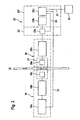
- FIG. 1 the monitoring device 18 is shown only schematically.
- the individual components of the monitoring device shows FIG. 2 ,
- the monitoring device 18 has an ultrasonic transmitter 19 and an ultrasonic receiver 20.
- the ultrasonic transmitter 19 has a pulse generator 19a and a power stage 19b and an ultrasonic transducer 19c, while the ultrasonic receiver comprises an ultrasonic transducer 20a and a signal amplifier 20b.
- the ultrasonic transducer 19c of the transmitter 19 and the ultrasonic transducer 20a of the receiver 20 are arranged on a sensor carrier 21 parallel to each other on both sides of the blood discharge line 7 downstream of the drip chamber 8 and upstream of the tube clamp 17 such that the blood flowing in the blood discharge line 7 is orthogonal Ultrasound is irradiated.
- the two ultrasonic transducers 19c and 20a may be piezoelectric ceramic discs. The gap between the two ultrasonic transducers forms an acoustic measuring section.
- the ultrasonic transmitter 19 operates in pulsed mode.
- the pulse generator 19a is controlled cyclically via a microcontroller 23c which is responsible for the sequence control and signal analysis and which is connected to the pulse generator 19a via a signal line 25.
- the pulse generator 19a then generates electrical signals which are supplied to the ultrasonic transducer 19c via the power stage 19b.
- the ultrasonic transducer 19c of the receiver 20 converts the ultrasonic signals back into electrical signals which are supplied to the signal amplifier 20b.
- the signal amplifier 20b filters and prepares the electrical signal so that it can be fed to an evaluation unit 23.
- the evaluation unit 23 has means 23 'for extracting a signal pattern that is characteristic of the time profile of the received ultrasonic pulses and means 23 "for comparing the characteristic signal pattern with a reference pattern.
- the signal pattern extracting means 23 comprises a peak detector 23a which determines the maximum signal amplitude of the pulses as a measure of the levels of ultrasonic pulses received by the ultrasonic transducer 20a, while the reference pattern comparison means 23 "determines an A / D Converter 23b and the microcontroller 23c.
- the analog voltage value supplied by the peak detector 23a is converted to a digital value by the A / D converter 23b for further signal processing.
- the peak detector 23a Prior to each delivery of an ultrasonic pulse via the ultrasonic transducer 19c, the peak detector 23a is reset by the microcontroller 23c, which is connected to the peak detector via a signal line 24.
- the microcontroller 23c Prior to each delivery of an ultrasonic pulse via the ultrasonic transducer 19c, the peak detector 23a is reset by the microcontroller 23c, which is connected to the peak detector via a signal line 24.
- the acoustic properties of the measuring section change when undissolved air, for example in the form of individual tiny air bubbles, d. H. Microbubbles in which blood flowing through the blood discharge line 7 is present.
- the microbubbles in the acoustic measuring section lead to a damping of the ultrasonic pulses and thus to a collapse of the maximum signal amplitude.
- the measurable over the course of the maximum amplitude amplitude thus undergoes a modulation corresponding to the currently effective attenuation of the acoustic measuring section.
- FIG. 3 shows such a signal pattern, which is used as a characteristic reference pattern. Only tiny signal changes (noise) can be seen, which have a relatively high frequency.
- FIGS. 4a and 4b show a signal pattern that is characteristic of the presence of a variety of microbubbles. Significantly, the burglaries of the signal amplitude can be seen.
- This in FIG. 4a shown signal pattern comprises a plurality of successive time intervals .DELTA.t.
- the time course of the signal pattern for one of the time intervals ⁇ t is in FIG. 4b shown enlarged. Typical are the relatively large changes in the signal, but have a relatively low frequency.
- FIGS. 5a and 5b show signal patterns that are characteristic of the presence of a few microbubbles.
- the comparison of the signal patterns of Figure 4a, 4b and 5a and 5b shows that in the signal pattern of Figure 5a, 5b Significantly fewer dips in the signal amplitude can be detected.
- a characteristic statistical characteristic is determined from the signal pattern for each of the successive time intervals.
- the characteristic statistical characteristic in the exemplary embodiment is the variance ⁇ 2 of the signal pattern. Since the variance is a feature where the measurements are by definition are adjusted from the mean, a suppression of the influence of the ambient conditions is achieved.
- Equation 1.1b The variance is calculated according to Equations 1.1b and 1.3.
- the mean value E (x) is not calculated in the equations from the data of the time interval .DELTA.t in which the evaluation is currently taking place, but uses the mean value determined in one or more of the preceding time intervals. However, this presupposes that the selected time interval ⁇ t is so small that changes in the mean value are negligible.
- the variance ⁇ 2 of the characteristic signal pattern is compared with the predetermined limit value. If the variance ⁇ 2 is greater than the limit, it is concluded that there are microbubbles in the predetermined time interval ⁇ t.
- a multiple threshold comparison allows the distinction between the presence of a few or many microbubbles.
- the evaluation unit 23 In the event that a dangerous for the patient volume of microbubbles in a predetermined time interval is detected, the evaluation unit 23 generates an alarm signal, which receives an alarm unit 26 which is connected via a control line 27 to the evaluation unit 23. The alarm unit 26 then generates an audible and / or visual alarm. At the same time, the alarm unit 26 generates a control signal, which via a signal line, not shown on the Control unit 15 of the dialysis device is applied. When this control signal is generated, the control unit 15 stops the dialysis treatment by stopping the blood pump 13 and operates the tube clamp 17 for clamping the blood discharge line 7.
- An alternative embodiment provides that alarm is given only if micro bubbles are detected in a plurality of time intervals.
- the evaluation unit 23 In the event that the evaluation unit 23 detects microbubbles in one of the time intervals .DELTA.t, the evaluation unit 23 generates a count signal. During the blood treatment or during a continuous or discontinuous sequence of time periods of the dialysis treatment, the number of counting signals generated by the evaluation unit 23 are counted in the successive measurements. The number of count signals is continuously compared during the dialysis treatment with another predetermined limit. When the count reaches the limit, the evaluation unit 23 again generates an alarm signal, so that the alarm unit 26 gives an audible and / or visual alarm and the control unit 15 interrupts the blood treatment. In this case, it is assumed that the total volume of air trapped in the blood poses a risk to the patient.
Landscapes
- Health & Medical Sciences (AREA)
- Life Sciences & Earth Sciences (AREA)
- Physics & Mathematics (AREA)
- Vascular Medicine (AREA)
- Heart & Thoracic Surgery (AREA)
- General Health & Medical Sciences (AREA)
- Anesthesiology (AREA)
- Chemical & Material Sciences (AREA)
- Biomedical Technology (AREA)
- Animal Behavior & Ethology (AREA)
- Engineering & Computer Science (AREA)
- Public Health (AREA)
- Veterinary Medicine (AREA)
- Cardiology (AREA)
- Acoustics & Sound (AREA)
- Hematology (AREA)
- Analytical Chemistry (AREA)
- Biochemistry (AREA)
- General Physics & Mathematics (AREA)
- Immunology (AREA)
- Pathology (AREA)
- External Artificial Organs (AREA)
- Infusion, Injection, And Reservoir Apparatuses (AREA)
Description
- Die Erfindung bezieht sich auf ein Verfahren zum Überwachen einer strömenden Flüssigkeit auf das Vorhandensein von Luft, insbesondere des in einem extrakorporalen Blutkreislauf einer extrakorporalen Blutbehandlungsvorrichtung strömenden Blutes, sowie ein Verfahren zur extrakorporalen Blutbehandlung mit einem extrakorporalen Blutkreislauf, wobei das Vorhandensein von Luft in dem extrakorporalen Blutkreislauf überwacht wird. Darüber hinaus betrifft die Erfindung eine Vorrichtung zum Überwachen einer strömenden Flüssigkeit, insbesondere des in einem extrakorporalen Kreislauf strömenden Blutes, auf das Vorhandensein von Luft, sowie eine Vorrichtung zur extrakorporalen Blutbehandlung mit einer Vorrichtung zur Überwachung des in dem extrakorporalen Kreislauf der Blutbehandlungsvorrichtung strömenden Blutes auf das Vorhandensein von Luft.
- Es sind verschiedene Verfahren zur extrakorporalen Blutbehandlung bekannt, bei denen das Blut des Patienten in einem extrakorporalen Blutkreislauf durch eine Blutbehandlungseinheit strömt. Eine der wesentlichen Komplikationen bei der extrakorporalen Blutbehandlung, beispielsweise Hämodialyse oder Hämofiltration, stellt die Möglichkeit des Eindringens von Luft in den extrakorporalen Blutkreislauf dar. Das gleiche Risiko besteht nicht nur bei extrakorporalen Blutbehandlungen, sondern auch bei Infusionen mit Infusionslösungen.
- Zum Abscheiden mitgeführter Luftblasen aus Blut oder Infusionslösungen dienen die bekannten Tropfkammern, die im venösen Zweig des extrakorporalen Blutkreislaufs bzw. in der Infusionsleitung angeordnet werden. Die bekannten Tropfkammern fangen die Luftblasen mit hoher Sicherheit ab. Dennoch besteht grundsätzlich die Gefahr, dass Luftblasen dem Patienten intravenös infundiert werden. Für Blutbehandlungsvorrichtungen schreibt daher die DIN/EN 60601-2-16 zur weiteren Erhöhung der Sicherheit Luftdetektoren vor, an deren Funktionssicherheit sehr hohe Anforderungen gestellt werden. Die bekannten Luftdetektoren beruhen auf der unterschiedlichen Absorption von Ultraschall in flüssigen und gasförmigen Medien sowie der Streuung von Ultraschall an Grenzflächen. Neben den Ultraschallsensoren sind Luftdetektoren bekannt, die auf den unterschiedlichen Dielektrizitätskonstanten und den unterschiedlichen Leitfähigkeiten von flüssigen und gasförmigen Medien basieren. Zur Detektion von Luft werden Signalimpulse in die strömende Flüssigkeit eingekoppelt, während die aus der strömenden Flüssigkeit austretenden Signalimpulse empfangen werden. Dabei wird auf das Vorhandensein von Luft dann geschlossen, wenn das Empfangssignal einen oder mehrere feste Referenzpegel unterschreitet.
- Um das Messergebnis nicht zu verfälschen, müssen Änderungen der Umgebungsbedingungen, die Einfluss auf das Empfangssignal haben, kompensiert werden. Hierfür finden verschiedene Kompensationsverfahren Verwendung. Eine Vorrichtung zur Erkennung von Luftblasen in strömenden Flüssigkeiten, die auf einer Ultraschallmessung mit einer Kompensation der Umgebungseinflüsse beruht, ist beispielsweise aus der
EP 1 182 452 A2 bekannt. - Die bekannten Verfahren zum Überwachen von strömenden Flüssigkeiten auf das Vorhandensein von Luft haben sich in der Praxis zur Detektion von relativ großen Luftblasen bewährt. Denn die relativ großen Luftblasen, die als Einzelblasen ein Volumen von ca. 1µl und als Bolus von ca. 50µl überschreiten, verursachen relativ kurze und große Signalveränderungen. Daher können die Einflüsse der sich dazu relativ langsam ändernde Umgebungseinflüsse leicht erkannt werden. So erfolgt die Ausregelung der Umgebungseinflüsse in einer wesentlich größeren Zeitdauer, als die Dauer der auf die Luftblasen zurückzuführenden Signaländerungen.
- Neben den relativ großen Einzelblasen können beispielsweise bei Dialysebehandlungen auch sehr kleine Luftbläschen, sogenannte Mikroblasen, auftreten. Sie entstehen typischerweise, wenn Luft aufgrund von Undichtigkeiten in den arteriellen Zweig des extrakorporalen Blutkreislaufs eindringen kann. Die in der Regel am Anfang noch relativ großen Einzelblasen werden zunächst durch die Blutpumpe zerkleinert. Beim anschließenden Durchgang durch die Kapillaren des Dialysators, die im Allgemeinen einen Innendurchmesser von ca. 0,2 mm haben, werden die Luftbläschen noch weiter zerkleinert, Die größeren Luftbläschen können im venösen Blasenfänger aufgrund ihrer Auftriebskraft abgeschieden werden, während die Mikroblasen, die im Allgemeinen einen Durchmesser von ca. 0,2 mm und ein Volumen von ca. 4nl haben, mit dem Blutstrom aus dem Blasenfänger transportiert werden und zum Patienten gelangen können. Im Blutstrom des Patienten befinden sich dann Mikroblasen mit einer kontinuierlichen Durehmesserverteiltung mit einem maximalen Durchmesser von ca. 0,3 mm.
- Vor einer Dialysebehandlung wird der extrakorporale Blutkreislauf in der Regel mit einer isotonischen Kochsalzlösung gespült. Dabei besteht die Gefahr, dass nicht freigespülte Luftblasen sich während der Behandlung lösen und dann in einer "Wolke" aus Mikroblasen in den Patienten unerkannt infundiert werden können.
- In der Literatur (Droste DW, Kühne K, Schaefer RM, Ringelstein EB. Detection of microemboli in the subclavian vein of patients undergoing haemodialysis an haemodiafiltration using pulsed Doppler ultrasound. Nephrol Dial Transplant 2002; 17:462-466) gibt es Hinweise, dass in Dialysebehandlungen typischerweise Mikroembolien auftreten, deren Ursache in dem Vorhandensein von Mikroblasen vermutet wird. Der menschliche Körper toleriert zwar relativ große Luftmengen, wenn sie intravenös verabreicht werden, da die Luft in der Lunge abgeatmet oder im Blut gelöst werden kann, In der Praxis wird eine kontinuierliche Luftinfusionsrate bis 1,5 ml/min bei einem Körpergewicht von 50 kg und einem maximalen Blutfluss von 600 ml/min akzeptiert. Sollten diese Grenzwerte jedoch überschritten werden, kann es zu ernsthaften Komplikationen während der Blutbehandlung kommen.
- Die
US 5,824,881 beschreibt ein Verfahren zum Überwachen eines strömenden Mediums auf das Vorhandensein von Luft, bei dem eine Folge von Signalimpulsen in das strömende Medium eingekoppelt und eine Folge von Signalimpulsen aus dem strömenden Medium ausgekoppelt werden. Aus dem ausgekoppelten Signal wird eine Detektion-Signatur ermittelt, die aus Gründen der Redundanz mit zwei Referenzsignaturen verglichen wird. Die Referenz-Signatur soll ein Zustand beschreiben, bei dem Luftblasen in der Leitung nicht enthalten sind. Bei einer Abweichung von Detektion-Signatur und Referenz-Signatur wird auf das Vorhandensein von Luftblasen geschlossen. - Der Erfindung liegt daher die Aufgabe zugrunde, ein Verfahren zum Überwachen einer strömenden Flüssigkeit auf das Vorhandensein von Luft anzugeben, das auch die Erkennung von relativ kleinen Luftblasen, insbesondere Mikroblasen zur Detektion unterschiedlicher Störfälle mit hoher Sicherheit erlaubt. Eine weitere Aufgabe der Erfindung ist, ein Verfahren zur extrakorporalen Blutbehandlung mit einem extrakorporalen Blutkreislauf anzugeben, mit dem sich mit hoher Sicherheit auch relativ kleine Luftblasen, insbesondere Mikroblasen im extrakorporalen Kreislauf erkennen lassen. Die Lösung dieser Aufgabe erfolgt erfindungsgemäß mit den Merkmalen der Patentansprüche 1 und 7.
- Darüber hinaus liegt der Erfindung die Aufgabe zugrunde, eine Vorrichtung zum Überwachen einer strömenden Flüssigkeit auf das Vorhandensein von relativ kleinen Luftblasen, insbesondere Mikroblasen, und eine extrakorporale Blutbehandlungsvorrichtung mit einer derartigen Überwachungsvorrichtung bereitzustellen. Die Lösung dieser Aufgaben erfolgt mit den Merkmalen der Ansprüche 8 und 14.
- Das Funktionsprinzip des erfindungsgemäßen Verfahrens und der erfindungsgemäßen Vorrichtung beruht darauf, dass eine Folge von Signalimpulsen oder ein kontinuierliches Signal in die strömende Flüssigkeit eingekoppelt und die aus der strömenden Flüssigkeit austretenden Signalimpulse bzw. das kontinuierliche Signal empfangen werden, wobei aus den empfangenen Signalimpulsen oder dem empfangenen kontinuierlichen Signal ein Signalmuster extrahiert wird, das für den zeitlichen Verlauf der empfangenen Signalimpulse oder des kontinuierlichen Signals in einem vorgegebenen Zeitintervall charakteristisch ist. Dieses charakteristische Signalmuster wird mit einem charakteristischen Referenzmuster verglichen, das für eine luftfreie Flüssigkeit charakteristisch ist, wobei auf das Vorhandensein von Luft dann geschlossen wird, wenn das charakteristische Signalmuster von dem charakteristischen Referenzmuster um ein vorgegebenes Maß abweicht. Grundsätzlich ist es möglich, alle aus der Mustererkennung bekannten Verfahren für die Auswertung des Empfangssignals heranzuziehen.
- Für den Vergleich von Signalmuster und Referenzmuster ist unerheblich, wie die Signalimpulse oder das kontinuierliche Signal physikalisch realisiert werden. Vorzugsweise sind die Signalimpulse Ultraschall-Impulse bzw. das kontinuierliche Signal ein Ultraschallsignal. Die Signale können aber auch elektrische Felder oder elektromagnetische Strahlung sein. Allein entscheidend ist, dass die Signale durch das Vorhandensein von Luft in der strömenden Flüssigkeit verändert werden.
- In einem definierten Zeitintervall Δt durchlaufen die Messstrecke ΔN Mikroblasen, die eine kontinuierliche Volumenverteilung aufweisen. Das Vorhandensein von Mikroblasen führt zu einer zeitlichen Veränderung des Empfangssignals, das als kontinuierliches Signal x(t) oder als kontinuierliche Folge von diskreten Werten x; (ll) vorliegen kann. Der zeitliche Signalverlauf des Empfangssignals stellt das charakteristische Signalmuster Emess,ΔN dar.
- Wenn keine Mikroblasen vorhanden sind, zeigt das Empfangssignal ein charakteristisches Signalmuster, das sich deutlich von dem charakteristischen Signalmuster des Empfangssignals unterscheidet, wenn Mikroblasen vorhanden sind. Das charakteristische Signalmuster wird nur von den Änderungen der Umgebungseinflüsse bestimmt, zu denen beispielsweise Störungen im Sender oder Empfänger oder Fluktuationen in der Dichte der strömenden Flüssigkeit zählen.
- Das charakteristische Signalmuster stellt im Allgemeinen ein verrauschtes Signal dar. Mit zunehmender Luftinfusionsrate steigt die Anzahl ΔN der Mikroblasen, wobei sich die Verteilung der Mikroblasen in der Regel zu größeren Volumina verändert. Dies führt zu häufigeren Signaländerungen mit zum Teil höheren Änderungen der Signalamplituden. Das empfangene Muster ändert sich von einem luftfreien Muster Emess,0 (charakteristisches Signalmuster) zu einem luftbeladenen Muster Emess,ΔN (charakteristisches Signalmuster).
- Das charakteristische Signalmuster Emess,0 wird als charakteristisches Referenzmuster Eref,O, vorzugsweise als Typmuster, festgelegt. Es ist auch möglich, das charakteristische Referenzmuster im Betrieb zyklisch neu zu bestimmen, wenn sichergestellt werden kann, dass sich keine Luftblasen in der Messstrecke befinden.
- Wenn sich das charakteristische Signalmuster von dem charakteristischen Referenzmuster signifikant unterscheidet, kann ein Alarmzustand erzeugt werden. Dadurch kann die größtmögliche Empfindlichkeit für die Erkennung von Mikroblasen realisiert werden. Wenn systembedingt eine genügende Trennschärfe zwischen dem luftfreien Zustand und einem den Patienten gefährdenden Zustand gegegeben ist, kann auch erst ab Erreichen eines vorgegebenen Grenzwertes ein Alarmzustand ausgelöst werden.
- Neben dem luftfreien charakteristischen Signalmuster Emess,0 als charakteristisches Referenzmuster Eref,0 können noch weitere Referenzmuster Eref, ΔN mit definierten Lufteinträgen verwendet werden, um zwischen verschiedenen Ereignissen unterscheiden zu können. Zum Beispiel kann ein Referenzmuster verwendet werden, das für eine einzelne Mikroblase charakteristisch ist, oder ein für die Überlagerung von n Mikroblasen charakteristisches Referenzmuster. Dadurch besteht die Möglichkeit, das Volumen der eingeschlossenen Luft als absolute Größe zu bestimmen. Auch kann ein Referenzmuster verwendet werden, das einen Lufteintrag definiert, bei dem der Grenzwert für eine Gefährdung erreicht wird.
- Das vorgegebene Zeitintervall, in dem der zeitliche Verlauf der empfangenen Signalimpulse oder des kontinuierlichen Signals bewertet wird, kann so klein gewählt werden dass die relativ langsamen Änderungen aufgrund der Umgebungseinflüsse als quasi konstant betrachtet werden können. Wenn dies der Fall ist, kann auf eine Kompensation der Änderungen aufgrund der Umgebungseinflüsse grundsätzlich verzichtet werden.
- Es ist von Vorteil, wenn das Zeitintervall Δt an die Größenordnung der Laufzeit der Mikroblasen durch die Messstrecke angepasst wird. Vorteilhaft ist, wenn das Zeitintervall Δt in Abhängigkeit von dem Blutfluss vorgegeben wird.
- Bei dem erfindungsgemäßen Verfahren oder der Vorrichtung wird der zeitliche Verlauf von Signal- und Referenzmuster nicht direkt miteinander verglichen. Im Allgemeinen ist es ausreichend, aus dem Signalmuster und dem Referenzmuster ein oder mehrere statistische Kenngrößen zu ermitteln, die für den zeitlichen Verlauf repräsentativ sind. Diese statistischen Kenngrößen können dann miteinander verglichen werden. Für das charakteristische Referenzmuster genügt im Allgemeinen ein oder mehrere definierte Kenngrößen.
- Aufgrund der Natur eines Mikroblasenstromes kann selbst bei einem konstanten Lufteintrag nicht exakt vorhergesagt werden, wie viele Mikroblasen ΔN die Messstrecke im Zeitintervall Δt passieren werden und welche Häufigkeitsverteilung die Volumina dieser ΔN Mikroblasen haben werden. Das charakteristische Signalmuster kann aber als das Ergebnis eines stochastischen Prozesses aufgefasst und mit den Algorithmen der statistischen Analyse von Zeitfolgen in vorteilhafter Weise mit verhältnismäßig geringem Aufwand bewertet werden. Die Bewertung kann auf der Grundlage einer Häufigkeitsverteilung im Zeitbereich oder auf der Grundlage einer Spektralanalyse stochastischer Prozesse erfolgen.
- Bei der Bewertung der Häufigkeitsverteilung im Zeitbereich wird das Empfangssignal als eindimensionale Zufallsgröße X aufgefasst, wobei ihre Realisierungen x einen diskreten oder stetigen Wertebereich umfassen können. Die statistischen Eigenschaften der Zufallsgröße werden vollständig durch ihre Verteilungsfunktion F(x) bzw. durch die kontinuierliche Verteilungsdichtefunktion f(x) oder durch die diskreten Wahrscheinlichkeiten wi beschrieben.
- Um den Aufwand zu reduzieren, ist es vorteilhaft, nicht die vollständigen Verteilungsfunktionen F(x) zu bestimmen und mit einander zu vergleichen, sondern sich auf ein oder mehrere charakteristische Merkmale zu beschränken. Die Definition dieser aussagekräftigen Kennwerte erfolgt in der Regel als Erwartungswerte einer Funktion g(x) gemäß:


- Bei einer stetigen Zufallsgröße X gilt Gl. (1.1a) und bei einer diskreten Zufallsgröße X gilt Gl. (1.1b), wobei wi die Wahrscheinlichkeit der Realisierung von xi ist.
- Eine weitere vorteilhafte Vereinfachung ist es, wenn der Mittelwert E(X) in den folgenden Gleichungen nicht aus den Daten des aktuellen Zeitintervalls Δt berechnet wird, sondern der von vorherigen Intervallen verwendet wird. Dies verursacht in der Regel zusätzliche Fehler von akzeptabler Größe, wenn das Zeitintervall Δt so klein gewählt wird, dass die typische zeitliche Änderung des Mittelwertes vernachlässigbar ist.
- Vorteilhafte Erwartungswerte sind:
- 1. Mittelwert:

- 2. Streuung oder Varianz σ2 bzw. Standardabweichung σ:

- 3. Momente k-ter Ordnung

- 4. Absolute Momente k-ter Ordnung

- 5. Momente k-ter Ordnung bezüglich c

- 6. Zentrierte Momente k-ter Ordnung

- 7. Absolute zentrierte Momente k-ter Ordnung

- 8. Schiefe der Verteilung von X
- 9. Exzess der Verteilung von X
- 10. Autokorrelationsfunktion
Der Korrelationsmittelwert bezieht sich auf einen zufälligen Prozess X.
Für zweidimensionale Zufallsgrößen sind die folgenden Kennwerte von Bedeutung. Ein Referenz-Muster Eref,ΔN kann z. B. als Realisierung der Zufallsgröße X1 und ein aktuell gemessenes Muster Emess kann als Realisierung der Zufallsgröße X2 aufgefasst werden. - 11. Kovarianz

- 12. Korrelationskoeffizient

- 13. Kreuzkorrelationsfunktion
Der Korrelationsmittelwert bezieht sich auf zwei verschiedene zufällige Prozesse X1, X2.
Neben der Bewertung der Häufigkeitsverteilung im Zeitbereich kann auch die Spektralanalyse zur Ermittlung von einer oder mehreren Kenngrößen aus den Signalmustern herangezogen werden. Das Ziel der Spektralanalyse (Fourier-Analyse) besteht darin, eine komplexe Zeitfolge mit zyklischen Komponenten in wenige zugrundeliegende harmonische Funktionen mit bestimmter Frequenz zu zerlegen, wobei diese Zeitfolge als Realisierung einer eindimensionalen Zufallsgröße X aufgefasst werden kann. Bei der Auswertung des Empfangssignals sind im Spektrum nur die Frequenzbereiche relevant, die durch Mikroblasen verändert werden. Dabei können die relativ hoch-frequenten Signalanteile aufgrund von empfangen Störungen oder durch elektronisches Rauschen durch Filterfunktionen eliminiert werden. Die relativ nieder-frequenten Signalanteile aufgrund der Änderung von Umgebungseinflüssen können ebenso ausgeblendet werden.
Vorteilhafte Kenngrößen sind:- 1. Periodogramm (Summe der Amplitudenquadrate bestimmter Frequenzen im Sinne eines Linienspektrums)
- 2. Spektraldichtefunktion (Energiedichtespektrum oder Leistungsdichtespektrum für bestimmte Frequenzen)
- 3. Anwendung von Filtern (Glättung innerhalb von Spektralfenstern)
- Bei dem Vergleich der Signalmuster kann es von Vorteil sein, mehrere Kenngrößen miteinander zu kombinieren, um die Trennschärfe für die Detektion von Mikroblasen zu erhöhen. Beispielsweise ist es möglich, auf einen Störfall dann zu schließen, wenn zwei Kenngrößen eine bestimmte Veränderung erfahren haben und eine dritte Kenngröße sich statistisch nicht signifikant verändert hat
- Als besonders vorteilhaft hat sich als statistische Kenngröße die Varianz erwiesen (Standardabweichung, Streumaß). Die Varianz ist ein Maß dafür, wie die einzelnen Daten um den Mittelwert verteilt sind, d. h. wie stark die Daten um den Mittelwert streuen. Da die Varianz eine vom Mittelwert bereinigte Größe ist, werden die Umgebungseinflüsse eliminiert, da die Änderung der absoluten Signalhöhe, beispielsweise des Signalmittelwertes, im Zeitintervall Δt nicht als eine Änderung des Musters bewertet wird.
- Bei einem weiteren bevorzugten Ausführungsbeispiel des erfindungsgemäßen Verfahrens und der Vorrichtung werden charakteristische Signalmuster in einer Folge von Zeitintervallen fortlaufend ermittelt und jeweils mit einem oder mehreren Referenzmustern verglichen. Ein Alarm kann schon dann gegeben werden, wenn eines der charakteristischen Signalmuster von dem charakteristischen Referenzmuster um ein vorgegebenes Maß abweicht Es ist aber auch möglich Alarm erst dann zu geben, wenn in einer bestimmten Anzahl von Zeitintervallen eine Abweichung um ein vorgegebenes Maß festgestellt wird. Die Anzahl der Ereignisse, bei der eine Abweichung festgestellt wird, wird während der Blutbehandlung gezählt. Die Anzahl der Ereignisse ist dabei ein Maß für das Volumen der insgesamt in der Flüssigkeit eingeschlossenen Luft.
- Eine weitere bevorzugte Ausführungsform sieht vor, eine Folge von Signalimpulsen anstelle eines kontinuierlichen Signals in die strömende Flüssigkeit einzukoppeln, wobei als charakteristisches Signalmuster die maximalen Signalamplituden der empfangenen Signalimpulse in einem vorgegebenen Zeitraum ermittelt werden. Anstelle der maximalen Signalamplitude können aber auch alle mit der Signalamplitude korrelierenden Größen bestimmt werden.
- Im Folgenden wird ein Ausführungsbeispiel der Erfindung unter Bezugnahme auf die Zeichnungen näher erläutert.
- Es zeigen:
- Figur 1
- die wesentlichen Komponenten einer Blutbehandlungsvorrichtung mit einem extrakorporalen Blutkreislauf in stark vereinfachter schematischer Darstellung zusammen mit einer Vorrichtung zum Überwachen des im Blutkreislauf strömenden Blutes auf das Vorhandensein von Luft,
- Figur 2
- die wesentlichen Komponenten eines Ausführungsbeispiels der Vorrichtung zum Überwachen des Blutes auf das Vorhandensein von Luft in schematischer Darstellung,
- Figur 3
- den zeitlichen Verlauf des charakteristischen Referenzmusters, wenn keine Luftblasen in der strömenden Flüssigkeit vorhanden sind,
- Figur 4a
- den zeitlichen Verlauf des charakteristischen Signalmusters, wenn viele Mikroblasen in der Flüssigkeit vorhanden sind,
- Figur 4b
- einen Ausschnitt des Signalmusters von
Figur 4a in vergrößerter Darstellung, - Figur 5a
- den zeitlichen Verlauf des charakteristischen Signalmusters, wenn wenige Mikroblasen in der Flüssigkeit vorhanden sind und
- Figur 5b
- einen Ausschnitt des Signalmusters von
Figur 5a in vergrößerter Darstellung. -
Figur 1 zeigt die wesentlichen Komponenten der Blutbehandlungsvorrichtung zusammen mit der Überwachungsvorrichtung. Die Blutbehandlungsvorrichtung, beispielsweise eine Hämodialysevorrichtung, weist einen Dialysator 1 auf, der durch eine semipermeable Membran 2 in eine Blutkammer 3 und eine Dialysierflüssigkeitskammer 4 getrennt ist. Der Einlass der Blutkammer ist mit einem Ende der Blutzuführleitung 5 verbunden, während der Auslass der Blutkammer 3 mit dem einen Ende einer Blutabführleitung 7 verbunden ist, in die eine Tropfkammer 8 geschaltet ist. Die anderen Enden der Blutzuführ- und -abführleitung 5, 7 sind mit einer arteriellen bzw. venösen Nadel 6, 6' verbunden. Zwischen Tropfkammer 8 und venöser Nadel 6' ist eine elektromagnetisch betätigbare venöse Schlauchklemme 17 an der Blutabführleitung 7 angeordnet. Die Blutzuführ- und -abführleitung 5, 7 stellen zusammen mit der Blutkammer 3 des Dialysators 1 den extrakorporalen Blutkreislauf I der Hämodialysevorrichtung dar. - Das Dialysierflüssigkeitssystem II der Dialysevorrichtung umfasst eine Einrichtung 9 zur Aufbereitung der Dialysierflüssigkeit, von der eine Dialysierflüssigkeitszuführleitung 10 abgeht, die zu der Dialysierflüssigkeitskammer 4 des Dialysators 1 führt. Von der Dialysierflüssigkeitskammer 4 geht eine Dialysierflüssigkeitsabführleitung 11 ab, die zu einem Auslass 12 führt.
- In der Blutzuführleitung 5 ist eine Blutpumpe 13 angeordnet, während in der Dialysierflüssigkeitsabführleitung 11 eine Dialysierflüssigkeitspumpe 14 angeordnet ist. Blutpumpe 13 und Dialysierflüssigkeitspumpe 14 fördern während der Blutbehandlung Blut im extrakorporalen Blutkreislauf I bzw. Dialysierflüssigkeit im Dialysierflüssigkeitssystem II.
- Die Hämodialysevorrichtung umfasst eine zentrale Steuereinheit 15, die über Steuerleitungen 16, 16', 16" mit der Blutpumpe 13 bzw. Dialysierflüssigkeitspumpe 14 bzw. Schlauchklemme 17 verbunden ist.
- Darüber hinaus verfügt die Hämodialysevorrichtung über eine Vorrichtung zum Überwachen des im extrakorporalen Blutkreislaufs I strömenden Blutes auf das Vorhandensein von Luft. Diese Überwachungsvorrichtung ist bei der beschriebenen Vorrichtung Bestandteil der Hämodialysevorrichtung, sie kann aber auch eine separate Baugruppe bilden.
- In
Figur 1 ist die Überwachungsvorrichtung 18 nur schematisch dargestellt. Die einzelnen Komponenten der Überwachungsvorrichtung zeigtFigur 2 . - Die Überwachungsvorrichtung 18 verfügt über einen Ultraschall-Sender 19 und einen Ultraschall-Empfänger 20. Der Ultraschallsender 19 weist einen Impulsgenerator 19a und eine Leistungsstufe 19b sowie einen Ultraschallwandler 19c auf, während der Ultraschall-Empfänger ein Ultraschall-Wandler 20a und einen Signalverstärker 20b aufweist. Der Ultraschallwandler 19c des Senders 19 und der Ultraschall-Wandler 20a des Empfängers 20 sind auf einem Sensorträger 21 parallel zueinander zu beiden Seiten der Blutabführleitung 7 stromab der Tropfkammer 8 und stromauf der Schlauchklemme 17 derart angeordnet, dass das in der Blutabführleitung 7 strömende Blut orthogonal mit Ultraschall durchstrahlt wird. Die beiden Ultraschall-Wandler 19c und 20a können piezoelektrische Keramikscheiben sein. Der Zwischenraum zwischen den beiden Ultraschallwandlern bildet eine akustische Messstrecke.
- Der Ultraschall-Sender 19 arbeitet im Impulsbetrieb. Dazu wird der Impulsgenerator 19a über einen für die Ablaufsteuerung und Signalanalyse verantwortlichen Mikrocontroller 23c, der mit dem Impulsgenerator 19a über eine Signaleitung 25 verbunden ist, zyklisch angesteuert. Der Impulsgenerator 19a erzeugt daraufhin elektrische Signale, die über die Leistungsstufe 19b dem Ultraschall-Wandler 19c zugeführt werden.
- Der Ultraschall-Wandler 19c des Empfängers 20 wandelt die Ultraschallsignale wieder in elektrische Signale um, die dem Signalverstärker 20b zugeführt werden. Der Signalverstärker 20b filtert und bereitet das elektrische Signal so auf, das es einer Auswerteinheit 23 zugeführt werden kann.
- Die Auswerteinheit 23 verfügt über Mittel 23' zum Extrahieren eines Signalmusters, das für den zeitlichen Verlauf der empfangenen Ultraschallimpulse charakteristisch ist und Mittel 23" zum Vergleichen des charakteristischen Signalmusters mit einem Referenzmuster.
- Die Mittel 23' zum Extrahieren des Signalmusters weisen einen Peakdetektor 23a auf, der als Maß für die Pegel der vom Ultraschallwandler 20a empfangenen Ultraschallimpulse die maximale Signalamplitude der Impulse bestimmt, während die Mittel 23" zum Vergleichen des charakteristischen Signalmusters mit einer Referenzmuster einen A/D-Wandler 23b und den Mikrokontroller 23c aufweisen.
- Der vom Peakdetektor 23a gelieferte analoge Spannungswert wird von dem A/D-Wandler 23b in einen digitalen Wert zur weiteren Signalverarbeitung überführt. Vor jeder Abgabe eines Ultraschallimpulses über den Ultraschallwandler 19c wird der Peakdetektor 23a von dem Mikrocontroller 23c zurückgesetzt, der über eine Signalleitung 24 mit dem Peakdetektor verbunden ist. Am Ausgang des Peakdetektors 23a liegt also ein Signalmuster an, das für den zeitlichen Verlauf der empfangenen Ultraschallimpulse in einem vorgegebenen Zeitintervall Δt charakteristisch ist. Das vorgegebene Zeitintervall Δt umfasst bei dem Ausführungsbeispiel insgesamt m = 128 Werte, wobei jeder Wert die maximale Amplitude des empfangenen Ultraschallimpulses darstellt.
- Aufgrund der konstanten Erregung des Ultraschallwandlers 19c des Senders 19 zeigen sich Veränderungen der akustischen Eigenschaften der Messstrecke in der Größe der maximalen Amplitude des vom Peakdetektor 23a gelieferten Analogsignals bzw. der Größe des am A/D-Wandler anliegenden Digitalsignals.
- Die akustischen Eigenschaften der Messstrecke ändern sich dann, wenn ungelöste Luft beispielsweise in Form von einzelnen winzigen Luftblasen, d. h. Mikroblasen, in dem durch die Blutabführleitung 7 strömenden Blut vorhanden sind. Die Mikroblasen in der akustischen Messstrecke führen zu einer Dämpfung der Ultraschallimpulse und somit zu einem Einbruch der maximalen Signalamplitude. Der über die Zeit messbare Verlauf der maximalen Amplitude erfährt also eine Modulation entsprechend der gerade wirksamen Dämpfung der akustischen Messstrecke.
- Wenn keine Mikroblasen in dem Blut vorhanden sind, können signifikante Einbrüche der Signalamplitude nicht beobachtet werden.
Figur 3 zeigt ein derartiges Signalmuster, das als charakteristisches Referenzmuster herangezogen wird. Es sind nur winzige Signaländerungen (Rauschen) zu erkennen, die eine relativ hohe Frequenz haben. - Die
Figuren 4a und 4b zeigen ein Signalmuster, das für das Vorhandensein von einer Vielzahl von Mikroblasen charakteristisch ist. Deutlich sind die Einbrüche der Signalamplitude zu erkennen. Das inFigur 4a gezeigte Signalmuster umfasst eine Vielzahl von aufeinanderfolgenden Zeitintervallen Δt. Der zeitliche Verlauf des Signalmusters für eines der Zeitintervalle Δt ist inFigur 4b vergrößert dargestellt. Typisch sind die relativ großen Änderungen des Signals, die aber eine relativ niedrige Frequenz haben. Das Zeitintervall Δt umfasst m=128 Werte. - Die
Figuren 5a und 5b zeigen Signalmuster, die für das Vorhandensein von wenigen Mikroblasen charakteristisch sind. Der Vergleich der Signalmuster vonFigur 4a, 4b und Figur 5a und 5b zeigt, dass in dem Signalmuster vonFigur 5a, 5b deutlich weniger Einbrüche der Signalamplitude zu erkennen sind. - Um das charakteristische Signalmuster mit dem Referenzmuster vergleichen zu können, wird in der Auswerteinheit 23, deren Bestandteil der Mikrokontroller 23c ist, eine charakteristische statistische Kenngröße aus dem Signalmuster für jedes der aufeinanderfolgenden Zeitintervalle bestimmt. Die charakteristische statistische Kenngröße ist bei dem Ausführungsbeispiel die Varianz σ2 des Signalmusters. Da die Varianz ein Merkmal ist, bei dem die Messwerte definitionsgemäß vom Mittelwert bereinigt sind, wird eine Unterdrückung des Einflusses der Umgebungsbedingungen erreicht.
- Die Berechnung der Varianz erfolgt nach den Gleichungen 1.1b und 1.3. Für die Wahrscheinlichkeiten wi in Gleichung 1.1b wird ein konstanter Wert eingesetzt. Da die Datenbasis eine Stichprobe und keine Grundgesamtheit ist, ergibt sich aus der Normierungsbedingung und der Forderung der Erwartungstreue dieser Wert zu wi=1/(m-1), wobei das Muster m=128 Werte umfasst.
- Der Mittelwert E(x) wird dabei in den Gleichungen nicht aus den Daten des Zeitintervalls Δt berechnet, in dem gerade die Auswertung erfolgt, sondern der in einem oder mehreren der vorausgegangenen Zeitintervalle ermittelte Mittelwert verwendet. Dies setzt aber voraus, dass das gewählte Zeitintervalls Δt so klein ist, dass Änderungen des Mittelwertes zu vernachlässigen sind.
- Bei dem Ausführungsbeispiel wird darauf verzichtet, auch aus dem charakteristischen Referenzmuster von
Figur 3 die Varianz zu berechnen. Es genügt, als Varianz für das Referenzmuster einen Grenzwert vorzugeben, bei dem angenommen wird, dass bei dessen Überschreiten eine Gefährdung für den Patienten gegeben ist. - In der Auswerteinheit 23 wird nun die Varianz σ2 des charakteristischen Signalmusters mit dem vorgegebenen Grenzwert verglichen. Wenn die Varianz σ2 größer als der Grenzwert ist, wird darauf geschlossen, dass in dem vorgegebenen Zeitintervall Δt Mikroblasen vorhanden sind. Ein Vergleich mit mehreren Grenzwerten erlaubt die Unterscheidung zwischen dem Vorliegen von wenigen oder vielen Mikroblasen.
- Für den Fall, dass ein für den Patienten gefährliches Volumen an Mikroblasen in einem vorgegebenen Zeitintervall detektiert wird, erzeugt die Auswerteinheit 23 ein Alarmsignal, das eine Alarmeinheit 26 empfängt, die über eine Steuerleitung 27 mit der Auswerteinheit 23 verbunden ist. Die Alarmeinheit 26 erzeugt dann einen akustischen und/oder optischen Alarm. Gleichzeitig erzeugt die Alarmeinheit 26 ein Steuersignal, das über eine nicht dargestellte Signalleitung an der Steuereinheit 15 der Dialysevorrichtung anliegt. Wenn dieses Steuersignal erzeugt wird, unterbricht die Steuereinheit 15 die Dialysebehandlung, indem sie die Blutpumpe 13 anhält und die Schlauchklemme 17 zum Abklemmen der Blutabführleitung 7 betätigt.
- Eine alternative Ausführungsform sieht vor, dass nur dann Alarm gegeben wird, wenn in einer Mehrzahl von Zeitintervallen Mikroblasen erkannt werden.
- Für den Fall, dass die Auswerteinheit 23 Mikroblasen in einem der Zeitintervalle Δt erkennt, erzeugt die Auswerteinheit 23 ein Zählsignal. Während der Blutbehandlung oder während einer kontinuierlichen oder diskontinuierlichen Folge von Zeitabschnitten der Dialysebehandlung werden in den aufeinanderfolgenden Messungen die Anzahl der von der Auswerteinheit 23 erzeugten Zählsignale gezählt. Die Anzahl der Zählsignale wird während der Dialysebehandlung fortlaufend mit einem weiteren vorgegebenen Grenzwert verglichen. Wenn der Zählstand den Grenzwert erreicht, erzeugt die Auswerteinheit 23 wieder ein Alarmsignal, so dass die Alarmeinheit 26 einen akustischen und/oder optischen Alarm gibt und die Steuereinheit 15 die Blutbehandlung unterbricht. In diesem Fall wird davon ausgegangen, dass das Gesamtvolumen der im Blut eingeschlossenen Luft eine Gefahr für den Patienten darstellt.
Claims (14)
- Verfahren zum Überwachen eines strömenden Mediums auf das Vorhandensein von Luft mit folgenden Verfahrensschritten:Einkoppeln einer Folge von Signalimpulsen oder eines kontinuierlichen Signals in das strömende Medium,Empfangen der aus dem strömenden Medium austretenden Signalimpulse oder des kontinuierlichen Signals,Extrahieren eines Signalmusters, das für den zeitlichen Verlauf der empfangenden Signalimpulse oder des kontinuierlichen Signals in einem vorgegebenen Zeitintervall charakteristisch ist undVergleichen des charakteristischen Signalmusters mit einem oder mehreren charakteristischen Referenzmustern, wobei auf das Vorhandensein von Luft geschlossen wird, wenn das charakteristische Signalmuster von mindestens einem charakteristischen Referenzmuster um ein vorgegebenes Maß abweicht,dadurch gekennzeichnet, dasszum Vergleichen des charakteristischen Signalmusters mit einem oder mehreren charakteristischen Referenzmustern aus dem charakteristischen Signalmuster ein oder mehrere statistische Kenngrößen ermittelt werden, die mit einer oder mehreren statistischen Referenzgrößen verglichen werden.
- Verfahren nach Anspruch 1, dadurch gekennzeichnet, dass charakteristische Signalmuster in einer Folge von Zeitintervallen fortlaufend ermittelt und jeweils mit einem oder mehreren Referenzmustern verglichen werden.
- Verfahren nach Anspruch 1 oder 2, dadurch gekennzeichnet, dass die statistische Kenngröße die Varianz ist.
- Verfahren nach einem der Ansprüche 1 bis 3, dadurch gekennzeichnet, dass charakteristische Signalmuster in einer Folge von Zeitintervallen fortlaufend ermittelt und jeweils mit einem oder mehreren Referenzmustern verglichen werden, wobei zur Berechnung der Varianz als statistische Kenngröße der in einem oder mehreren der vorausgehenden Zeitintervalle berechnete Mittelwert herangezogen wird.
- Verfahren nach einem der Ansprüche 1 bis 4, dadurch gekennzeichnet, dass die maximalen Signalamplituden der empfangenen Signalimpulse ermittelt werden, wobei das charakteristische Signalmuster die in einem vorgegebenen Zeitintervall auftretende Folge der maximalen Amplituden der Signalimpulse ist.
- Verfahren nach einem Ansprüche 1 bis 5, dadurch gekennzeichnet, dass die Folge von Signalimpulsen oder das kontinuierliche Signal eine Folge von Ultraschallimpulsen bzw. ein kontinuierliches Ultraschallsignal ist.
- Verfahren zur extrakorporalen Blutbehandlung mit einem extrakorporalen Blutkreislauf, wobei das Vorhandensein von Luft im extrakorporalen Blutkreislauf mit einem Verfahren nach einem der Ansprüche 1 bis 6 überwacht wird.
- Vorrichtung zum Überwachen eines strömenden Mediums auf das Vorhandensein von Luft mit
Mitteln (19) zum Einkoppeln einer Folge von Signalimpulsen und eines kontinuierlichen Signals in das strömende Medium,
Mitteln (20) zum Empfangen der aus der strömenden Flüssigkeit austretenden Signalimpulse oder des kontinuierlichen Signals und
einer Auswerteinheit (23), die aufweist:Mittel (23') zum Extrahieren eines Signalmusters, das für den zeitlichen Verlauf der empfangenen Signalimpulse oder des kontinuierlichen Signals in einem vorgegebenen Zeitintervall charakteristisch ist undMittel (23") zum Vergleichen des charakteristischen Signalmusters mit einem oder mehreren charakteristischen Referenzmustern, wobei auf das Vorhandensein von Luft geschlossen wird, wenn das charakteristische Signalmuster von mindestens einem charakteristischen Referenzmuster um ein vorgegebenes Maß abweicht,dadurch gekennzeichnet, dass die Mittel (23") zum Vergleichen des charakteristischen Signalmusters mit einem oder mehreren charakteristischen Referenzmustern derart ausgebildet sind, dass aus dem charakteristischen Signalmuster ein oder mehrere statistische Kenngrößen ermittelt werden, die mit einer oder mehreren statistischen Referenzgrößen verglichen werden. - Vorrichtung nach Anspruch 8, dadurch gekennzeichnet, dass die Mittel (23') zum Extrahieren eines Signalmusters derart ausgebildet sind, dass charakteristische Signalmuster in einer Folge von Zeitintervallen fortlaufend ermittelt und jeweils mit einem oder mehreren Referenzmustern verglichen werden.
- Vorrichtung nach Anspruch 8 oder 9, dadurch gekennzeichnet, dass die Mittel (23 ") zum Vergleichen des charakteristischen Signalmuster mit einem oder mehreren charakteristischen Referenzmustern derart ausgebildet sind, dass als statistische Kenngröße die Varianz berechnet wird.
- Vorrichtung nach einem der Ansprüche 8 bis 10, dadurch gekennzeichnet, dass die Mittel (23") zum Vergleichen des charakteristischen Signalmuster mit einem oder mehreren charakteristischen Referenzmustern derart ausgebildet sind, dass charakteristische Signalmuster in einer Folge von Zeitintervallen fortlaufend ermittelt und jeweils mit einem oder mehreren Referenzmustern verglichen werden, wobei zur Berechnung der Varianz als statistische Kenngröße der in einem oder mehreren der vorausgehenden Zeitintervalle berechnete Mittelwert herangezogen wird.
- Vorrichtung nach einem der Ansprüche 8 bis 11, dadurch gekennzeichnet, dass die Mittel (23') zum Extrahieren eines Signalmusters derart ausgebildet sind, dass als charakteristisches Signalmuster die in einem vorgegebenem Zeitintervall auftretende Folge der maximalen Amplituden der Signalimpulse extrahiert wird.
- Vorrichtung nach einem der Ansprüche 8 bis 12, dadurch gekennzeichnet, dass die Mittel zum Senden der Folge von Signalimpulsen oder des kontinuierlichen Signals ein Ultraschall-Sender (19), und die Mittel zum Empfangen der Ultraschallimpulse ein Ultraschall-Empfänger (20) sind.
- Vorrichtung zur extrakorporalen Blutbehandlung mit einem extrakorporalen Blutkreislauf und einer Vorrichtung nach einem der Ansprüche 8 bis 13, wobei das Vorhandensein von Luft im extrakorporalen Blutkreislauf überwacht wird.
Priority Applications (1)
| Application Number | Priority Date | Filing Date | Title |
|---|---|---|---|
| PL06724358T PL1886130T3 (pl) | 2005-06-03 | 2006-04-15 | Sposób i urządzenie do nadzorowania przepływającego płynu pod względem obecności powietrza |
Applications Claiming Priority (2)
| Application Number | Priority Date | Filing Date | Title |
|---|---|---|---|
| DE102005025515A DE102005025515A1 (de) | 2005-06-03 | 2005-06-03 | Verfahren und Vorrichtung zum Überwachen einer strömenden Flüssigkeit auf das Vorhandensein von Luft |
| PCT/EP2006/003484 WO2006128520A1 (de) | 2005-06-03 | 2006-04-15 | Verfahren und vorrichtung zum überwachen einer strömenden flüssigkeit auf das vorhandensein von luft |
Publications (2)
| Publication Number | Publication Date |
|---|---|
| EP1886130A1 EP1886130A1 (de) | 2008-02-13 |
| EP1886130B1 true EP1886130B1 (de) | 2013-09-18 |
Family
ID=36942641
Family Applications (1)
| Application Number | Title | Priority Date | Filing Date |
|---|---|---|---|
| EP06724358.4A Expired - Lifetime EP1886130B1 (de) | 2005-06-03 | 2006-04-15 | Verfahren und vorrichtung zum überwachen einer strömenden flüssigkeit auf das vorhandensein von luft |
Country Status (8)
| Country | Link |
|---|---|
| US (1) | US8104348B2 (de) |
| EP (1) | EP1886130B1 (de) |
| JP (1) | JP4711454B2 (de) |
| CN (1) | CN101189510B (de) |
| DE (1) | DE102005025515A1 (de) |
| ES (1) | ES2433291T3 (de) |
| PL (1) | PL1886130T3 (de) |
| WO (1) | WO2006128520A1 (de) |
Families Citing this family (43)
| Publication number | Priority date | Publication date | Assignee | Title |
|---|---|---|---|---|
| US9026370B2 (en) | 2007-12-18 | 2015-05-05 | Hospira, Inc. | User interface improvements for medical devices |
| US20110082373A1 (en) * | 2009-06-04 | 2011-04-07 | Gurley John C | Methods and apparatus for the detection of cardiopulmonary defects |
| US8394087B2 (en) * | 2009-09-24 | 2013-03-12 | Vivant Medical, Inc. | Optical detection of interrupted fluid flow to ablation probe |
| US9518958B2 (en) | 2012-12-18 | 2016-12-13 | Deka Products Limited Partnership | System, method, and apparatus for detecting air in a fluid line using active rectification |
| DE102010035498B4 (de) * | 2010-08-25 | 2012-08-02 | Fresenius Medical Care Deutschland Gmbh | Verfahren zum Detektieren von Leckagen, System und medizintechnische Behandlungsvorrichtung |
| US9907908B2 (en) | 2011-03-08 | 2018-03-06 | Baxter International Inc. | Non-invasive radio frequency medical fluid level and volume detection system and method |
| EP2744533B1 (de) | 2011-08-19 | 2019-12-11 | ICU Medical, Inc. | Mustererkennungssystem und verfahren zum nachweis von blockierten flüssigkeitstropfen in einer flüssigkeitszufuhrleitung eines infusionssystems |
| WO2013028497A1 (en) | 2011-08-19 | 2013-02-28 | Hospira, Inc. | Systems and methods for a graphical interface including a graphical representation of medical data |
| US10022498B2 (en) | 2011-12-16 | 2018-07-17 | Icu Medical, Inc. | System for monitoring and delivering medication to a patient and method of using the same to minimize the risks associated with automated therapy |
| EP2830687B1 (de) | 2012-03-30 | 2019-07-24 | ICU Medical, Inc. | Luftdetektionssystem und verfahren zum nachweis von luft in einer pumpe eines infusionssystems |
| DE102012009192A1 (de) | 2012-05-10 | 2013-11-14 | Fresenius Medical Care Deutschland Gmbh | Vorrichtung zur extrakorporalen Blutbehandlung und Verfahren zum Ermitteln einer Blutflussrate für eine extrakorporale Blutbehandlungsvorrichtung |
| CA3089257C (en) | 2012-07-31 | 2023-07-25 | Icu Medical, Inc. | Patient care system for critical medications |
| DE102012024341B3 (de) * | 2012-12-13 | 2014-02-13 | Fresenius Medical Care Deutschland Gmbh | Vorrichtung und Verfahren zum Überwachen eines extrakorporalen Blutkreislaufs zur Erkennung von Luftblasen |
| CA2913421C (en) | 2013-05-24 | 2022-02-15 | Hospira, Inc. | Multi-sensor infusion system for detecting air or an occlusion in the infusion system |
| ES2838450T3 (es) | 2013-05-29 | 2021-07-02 | Icu Medical Inc | Sistema de infusión que utiliza uno o más sensores e información adicional para hacer una determinación de aire en relación con el sistema de infusión |
| AU2014274122A1 (en) | 2013-05-29 | 2016-01-21 | Icu Medical, Inc. | Infusion system and method of use which prevents over-saturation of an analog-to-digital converter |
| DE102013224389A1 (de) * | 2013-11-28 | 2015-05-28 | GAMPT mbH, Gesellschaft für angewandte medizinische Physik und Technik | Verfahren zur Ermittlung und/oder Überwachung des Zustandes eines extrakorporalen Fluides oder Fluidstroms mittels Ultraschall |
| EP3110474B1 (de) | 2014-02-28 | 2019-12-18 | ICU Medical, Inc. | Infusionssystem und verfahren mit verwendung von optischer luftblasenerkennung mit zwei wellenlängen |
| US9248221B2 (en) | 2014-04-08 | 2016-02-02 | Incuvate, Llc | Aspiration monitoring system and method |
| JP2017517302A (ja) | 2014-05-29 | 2017-06-29 | ホスピーラ インコーポレイテッド | 構成可能閉ループ送達速度キャッチアップを有する注入システムおよびポンプ |
| US11344668B2 (en) | 2014-12-19 | 2022-05-31 | Icu Medical, Inc. | Infusion system with concurrent TPN/insulin infusion |
| US10850024B2 (en) | 2015-03-02 | 2020-12-01 | Icu Medical, Inc. | Infusion system, device, and method having advanced infusion features |
| DE102015103938B4 (de) * | 2015-03-17 | 2025-07-03 | B.Braun Avitum Ag | Gasblasen- und/oder Festkörperdetektor auf Ultraschallbasis, Dialysegerät und Verfahren für einen derartigen Detektor |
| CN104931580A (zh) * | 2015-06-01 | 2015-09-23 | 北京哈特凯尔医疗科技有限公司 | 一种液体媒介中空气检测系统 |
| US10702292B2 (en) | 2015-08-28 | 2020-07-07 | Incuvate, Llc | Aspiration monitoring system and method |
| US10226263B2 (en) | 2015-12-23 | 2019-03-12 | Incuvate, Llc | Aspiration monitoring system and method |
| EP3454922B1 (de) | 2016-05-13 | 2022-04-06 | ICU Medical, Inc. | Infusionspumpensystem mit gemeinsamer leitung zur automatischen spülung |
| AU2017277804B2 (en) | 2016-06-10 | 2022-05-26 | Icu Medical, Inc. | Acoustic flow sensor for continuous medication flow measurements and feedback control of infusion |
| US10575816B2 (en) * | 2017-01-25 | 2020-03-03 | Insightec, Ltd. | Cavitation localization |
| US10576196B2 (en) | 2017-04-10 | 2020-03-03 | Fresenius Medical Care Holdings, Inc. | Optical detection of air bubbles in either saline or blood or a mixture of both |
| US10089055B1 (en) | 2017-12-27 | 2018-10-02 | Icu Medical, Inc. | Synchronized display of screen content on networked devices |
| EP3683575A1 (de) * | 2019-01-18 | 2020-07-22 | TE Connectivity Norge AS | System und verfahren zur detektion des vorhandenseins von blasen in wässrigen lösungen |
| DE102019202824B4 (de) * | 2019-03-01 | 2021-02-11 | Fraunhofer-Gesellschaft zur Förderung der angewandten Forschung e.V. | Messsystem zur Überwachung der Inhaltsstoffe, physikalischer Parameter und/oder Homogenität von durch einen Kanal gefördertem Blut |
| US11278671B2 (en) | 2019-12-04 | 2022-03-22 | Icu Medical, Inc. | Infusion pump with safety sequence keypad |
| WO2022020184A1 (en) | 2020-07-21 | 2022-01-27 | Icu Medical, Inc. | Fluid transfer devices and methods of use |
| EP3991764B1 (de) | 2020-10-27 | 2024-03-06 | Bellco S.r.l. | Durchflussmesser zum dosieren von wasser in einem dialysesystem |
| US12318528B2 (en) | 2020-10-30 | 2025-06-03 | Mozarc Medical Us Llc | Variable orifice fistula graft |
| EP3991770B1 (de) | 2020-10-30 | 2024-10-30 | Bellco S.r.l. | Dialysekassette mit pumpfunktionen |
| EP4008376A1 (de) | 2020-12-03 | 2022-06-08 | Medtronic, Inc. | Flexibles rohr-routing-zubehör für peritoneal dialysis system |
| US11135360B1 (en) | 2020-12-07 | 2021-10-05 | Icu Medical, Inc. | Concurrent infusion with common line auto flush |
| US12599716B2 (en) | 2021-10-12 | 2026-04-14 | Icu Medical, Inc. | Intravenous infusion pump with cassette insertion and pump control user interface |
| USD1091564S1 (en) | 2021-10-13 | 2025-09-02 | Icu Medical, Inc. | Display screen or portion thereof with graphical user interface for a medical device |
| AU2022407460A1 (en) | 2021-12-10 | 2024-06-27 | Icu Medical, Inc. | Medical fluid compounding systems with coordinated flow control |
Family Cites Families (9)
| Publication number | Priority date | Publication date | Assignee | Title |
|---|---|---|---|---|
| JPS5846963A (ja) * | 1981-09-16 | 1983-03-18 | 横河電機株式会社 | 血液透析用超音波検出装置 |
| US4651555A (en) | 1984-09-11 | 1987-03-24 | Introtek Corporation | Apparatus for detecting discontinuities in a fluid stream |
| DE4013402C2 (de) * | 1990-04-26 | 1994-03-24 | Infurex Ag Cham | Verfahren und Vorrichtung zur Erkennung von Gasblasen in einer mit Flüssigkeit gefüllten Leitung, insbesondere einer flexiblen, schlauchförmigen Leitung oder einem Container |
| US5394732A (en) | 1993-09-10 | 1995-03-07 | Cobe Laboratories, Inc. | Method and apparatus for ultrasonic detection of air bubbles |
| US5824881A (en) * | 1996-09-13 | 1998-10-20 | Cobe Laboratories | Gas/fluid detector for contained fluid systems |
| JPH10216227A (ja) * | 1997-02-03 | 1998-08-18 | Terumo Corp | 輸液ポンプ |
| US6489896B1 (en) * | 2000-11-03 | 2002-12-03 | Baxter International Inc. | Air in-line sensor for ambulatory drug infusion pump |
| JP3840379B2 (ja) * | 2001-01-29 | 2006-11-01 | 株式会社日立製作所 | 内燃機関の吸気量計測装置 |
| US6622542B2 (en) * | 2001-03-20 | 2003-09-23 | Therox, Inc. | Bubble detector and method of use thereof |
-
2005
- 2005-06-03 DE DE102005025515A patent/DE102005025515A1/de not_active Ceased
-
2006
- 2006-04-15 JP JP2008513949A patent/JP4711454B2/ja not_active Expired - Lifetime
- 2006-04-15 US US11/921,624 patent/US8104348B2/en active Active
- 2006-04-15 EP EP06724358.4A patent/EP1886130B1/de not_active Expired - Lifetime
- 2006-04-15 WO PCT/EP2006/003484 patent/WO2006128520A1/de not_active Ceased
- 2006-04-15 PL PL06724358T patent/PL1886130T3/pl unknown
- 2006-04-15 CN CN2006800196932A patent/CN101189510B/zh not_active Expired - Lifetime
- 2006-04-15 ES ES06724358T patent/ES2433291T3/es not_active Expired - Lifetime
Also Published As
| Publication number | Publication date |
|---|---|
| DE102005025515A1 (de) | 2006-12-07 |
| CN101189510B (zh) | 2011-02-02 |
| US8104348B2 (en) | 2012-01-31 |
| US20090205426A1 (en) | 2009-08-20 |
| ES2433291T3 (es) | 2013-12-10 |
| EP1886130A1 (de) | 2008-02-13 |
| JP4711454B2 (ja) | 2011-06-29 |
| CN101189510A (zh) | 2008-05-28 |
| JP2008541897A (ja) | 2008-11-27 |
| PL1886130T3 (pl) | 2014-03-31 |
| WO2006128520A1 (de) | 2006-12-07 |
Similar Documents
| Publication | Publication Date | Title |
|---|---|---|
| EP1886130A1 (de) | Verfahren und vorrichtung zum überwachen einer strömenden flüssigkeit auf das vorhandensein von luft | |
| DE102005025500B3 (de) | Verfahren und Vorrichtung zum Überwachen einer strömenden Flüssigkeit auf das Vorhandensein von Luft | |
| EP1584339B1 (de) | Verfahren und Vorrichtung zur Überwachung eines Gefäßzugangs | |
| EP1327457B1 (de) | Vorrichtung zur Detektion einer Leckage in einem Flüssigkeitssystem einer Blutbehandlungsvorrichtung | |
| EP2068973B1 (de) | Verfahren und vorrichtung zur erkennung von luft in einem flüssigkeitssystem, insbesondere in einem extrakorporalen blutkreislauf einer blutbehandlungsvorrichtung | |
| EP1245242B1 (de) | Verfahren und Vorrichtung zum Erkennen von Stenosen in einem Schlauchleitungssystem | |
| EP2150292B1 (de) | Vorrichtung zur überwachung einer blutbehandelungseinheit einer extrakorporalen blutbehandlungsvorrichtung | |
| EP2259812B1 (de) | Verfahren und vorrichtung zur überwachung eines gefässzugangs sowie extrakorporale blutbehandlungsvorrichtung mit einer vorrichtung zur überwachung eines gefässzugangs | |
| DE102004023080B4 (de) | Verfahren und Vorrichtung zur Überwachung der Zufuhr von Substitutionsflüssigkeit während einer extrakorporalen Blutbehandlung | |
| EP1491222B1 (de) | Vorrichtung zur extrakorporalen Blutbehandlung mit einer Einrichtung zur Überprüfung eines Sterilfilters und Verfahren zum Überprüfen eines Sterilfilters einer extrakorporalen Blutbehandlungsvorrichtung | |
| EP2913071B1 (de) | Vorrichtung zur Erkennung eines Fehlers im extrakorporalen Blutkreislauf | |
| DE3720664A1 (de) | Vorrichtung zur behandlung von blut durch dialyse und/oder filtration | |
| EP3074060B1 (de) | Verfahren zur ermittlung und/oder überwachung des zustands eines extrakorporalen fluides oder fluidstroms mittels ultraschall | |
| EP2605811A1 (de) | Vorrichtung zur ermittlung und/oder überwachung von fremdstrukturen in einem fluid oder einem fluidstrom sowie verfahren hierzu | |
| EP2349394B1 (de) | Verfahren und vorrichtung zur erkennung einer paravasalen blutung | |
| EP1668352A1 (de) | Akustisches verfahren zum messen einer signallaufzeit in einer medizinischen flüssigkeit und vorrichtung zur anwendung des verfahrens | |
| DE10033192B4 (de) | Verfahren zur Detektion arterieller Einlaufprobleme während einer extrakorporalen Blutbehandlung und extrakorporale Blutbehandlungsvorrichtung | |
| EP3365044B1 (de) | Vorrichtung, system und verfahren zur druckbasierten erkennung eines gerinnsels | |
| DE3720667A1 (de) | Haemodialyse- und haemofiltrationsvorrichtung | |
| EP2783716B1 (de) | Verfahren und Vorrichtung zur Erkennung einer Rezirkulation in einem Shunt | |
| DE102015120099B4 (de) | Ultraschallsonde zur Detektion von Fremdstrukturen in Fluiden |
Legal Events
| Date | Code | Title | Description |
|---|---|---|---|
| PUAI | Public reference made under article 153(3) epc to a published international application that has entered the european phase |
Free format text: ORIGINAL CODE: 0009012 |
|
| 17P | Request for examination filed |
Effective date: 20071102 |
|
| AK | Designated contracting states |
Kind code of ref document: A1 Designated state(s): AT BE BG CH CY CZ DE DK EE ES FI FR GB GR HU IE IS IT LI LT LU LV MC NL PL PT RO SE SI SK TR |
|
| RIN1 | Information on inventor provided before grant (corrected) |
Inventor name: FRITSCHE, TOBIAS Inventor name: SCHNEIDER, JOCHEN Inventor name: GAGEL, ALFRED Inventor name: BALSCHAT, KLAUS Inventor name: NICHOLAS, OLAF Inventor name: MUENCH, HANS-JOACHIM Inventor name: SPICKERMANN, RAINER Inventor name: KIRCHNER, STEFFEN Inventor name: ZUR HOST-MEYER, SANTER |
|
| DAX | Request for extension of the european patent (deleted) | ||
| 17Q | First examination report despatched |
Effective date: 20091118 |
|
| GRAP | Despatch of communication of intention to grant a patent |
Free format text: ORIGINAL CODE: EPIDOSNIGR1 |
|
| INTG | Intention to grant announced |
Effective date: 20130404 |
|
| GRAS | Grant fee paid |
Free format text: ORIGINAL CODE: EPIDOSNIGR3 |
|
| GRAA | (expected) grant |
Free format text: ORIGINAL CODE: 0009210 |
|
| AK | Designated contracting states |
Kind code of ref document: B1 Designated state(s): AT BE BG CH CY CZ DE DK EE ES FI FR GB GR HU IE IS IT LI LT LU LV MC NL PL PT RO SE SI SK TR |
|
| REG | Reference to a national code |
Ref country code: GB Ref legal event code: FG4D Free format text: NOT ENGLISH |
|
| REG | Reference to a national code |
Ref country code: CH Ref legal event code: EP |
|
| REG | Reference to a national code |
Ref country code: IE Ref legal event code: FG4D Free format text: LANGUAGE OF EP DOCUMENT: GERMAN |
|
| REG | Reference to a national code |
Ref country code: AT Ref legal event code: REF Ref document number: 633031 Country of ref document: AT Kind code of ref document: T Effective date: 20131015 |
|
| REG | Reference to a national code |
Ref country code: DE Ref legal event code: R096 Ref document number: 502006013211 Country of ref document: DE Effective date: 20131114 |
|
| REG | Reference to a national code |
Ref country code: ES Ref legal event code: FG2A Ref document number: 2433291 Country of ref document: ES Kind code of ref document: T3 Effective date: 20131210 |
|
| REG | Reference to a national code |
Ref country code: SE Ref legal event code: TRGR |
|
| PG25 | Lapsed in a contracting state [announced via postgrant information from national office to epo] |
Ref country code: CY Free format text: LAPSE BECAUSE OF FAILURE TO SUBMIT A TRANSLATION OF THE DESCRIPTION OR TO PAY THE FEE WITHIN THE PRESCRIBED TIME-LIMIT Effective date: 20130703 Ref country code: LT Free format text: LAPSE BECAUSE OF FAILURE TO SUBMIT A TRANSLATION OF THE DESCRIPTION OR TO PAY THE FEE WITHIN THE PRESCRIBED TIME-LIMIT Effective date: 20130918 |
|
| REG | Reference to a national code |
Ref country code: NL Ref legal event code: VDEP Effective date: 20130918 |
|
| REG | Reference to a national code |
Ref country code: LT Ref legal event code: MG4D |
|
| PG25 | Lapsed in a contracting state [announced via postgrant information from national office to epo] |
Ref country code: SI Free format text: LAPSE BECAUSE OF FAILURE TO SUBMIT A TRANSLATION OF THE DESCRIPTION OR TO PAY THE FEE WITHIN THE PRESCRIBED TIME-LIMIT Effective date: 20130918 Ref country code: GR Free format text: LAPSE BECAUSE OF FAILURE TO SUBMIT A TRANSLATION OF THE DESCRIPTION OR TO PAY THE FEE WITHIN THE PRESCRIBED TIME-LIMIT Effective date: 20131219 Ref country code: FI Free format text: LAPSE BECAUSE OF FAILURE TO SUBMIT A TRANSLATION OF THE DESCRIPTION OR TO PAY THE FEE WITHIN THE PRESCRIBED TIME-LIMIT Effective date: 20130918 Ref country code: LV Free format text: LAPSE BECAUSE OF FAILURE TO SUBMIT A TRANSLATION OF THE DESCRIPTION OR TO PAY THE FEE WITHIN THE PRESCRIBED TIME-LIMIT Effective date: 20130918 |
|
| PG25 | Lapsed in a contracting state [announced via postgrant information from national office to epo] |
Ref country code: CY Free format text: LAPSE BECAUSE OF FAILURE TO SUBMIT A TRANSLATION OF THE DESCRIPTION OR TO PAY THE FEE WITHIN THE PRESCRIBED TIME-LIMIT Effective date: 20130918 |
|
| PG25 | Lapsed in a contracting state [announced via postgrant information from national office to epo] |
Ref country code: SK Free format text: LAPSE BECAUSE OF FAILURE TO SUBMIT A TRANSLATION OF THE DESCRIPTION OR TO PAY THE FEE WITHIN THE PRESCRIBED TIME-LIMIT Effective date: 20130918 Ref country code: IS Free format text: LAPSE BECAUSE OF FAILURE TO SUBMIT A TRANSLATION OF THE DESCRIPTION OR TO PAY THE FEE WITHIN THE PRESCRIBED TIME-LIMIT Effective date: 20140118 Ref country code: CZ Free format text: LAPSE BECAUSE OF FAILURE TO SUBMIT A TRANSLATION OF THE DESCRIPTION OR TO PAY THE FEE WITHIN THE PRESCRIBED TIME-LIMIT Effective date: 20130918 Ref country code: EE Free format text: LAPSE BECAUSE OF FAILURE TO SUBMIT A TRANSLATION OF THE DESCRIPTION OR TO PAY THE FEE WITHIN THE PRESCRIBED TIME-LIMIT Effective date: 20130918 Ref country code: RO Free format text: LAPSE BECAUSE OF FAILURE TO SUBMIT A TRANSLATION OF THE DESCRIPTION OR TO PAY THE FEE WITHIN THE PRESCRIBED TIME-LIMIT Effective date: 20130918 Ref country code: NL Free format text: LAPSE BECAUSE OF FAILURE TO SUBMIT A TRANSLATION OF THE DESCRIPTION OR TO PAY THE FEE WITHIN THE PRESCRIBED TIME-LIMIT Effective date: 20130918 |
|
| REG | Reference to a national code |
Ref country code: DE Ref legal event code: R097 Ref document number: 502006013211 Country of ref document: DE |
|
| PG25 | Lapsed in a contracting state [announced via postgrant information from national office to epo] |
Ref country code: PT Free format text: LAPSE BECAUSE OF FAILURE TO SUBMIT A TRANSLATION OF THE DESCRIPTION OR TO PAY THE FEE WITHIN THE PRESCRIBED TIME-LIMIT Effective date: 20140120 |
|
| PLBE | No opposition filed within time limit |
Free format text: ORIGINAL CODE: 0009261 |
|
| STAA | Information on the status of an ep patent application or granted ep patent |
Free format text: STATUS: NO OPPOSITION FILED WITHIN TIME LIMIT |
|
| 26N | No opposition filed |
Effective date: 20140619 |
|
| PG25 | Lapsed in a contracting state [announced via postgrant information from national office to epo] |
Ref country code: DK Free format text: LAPSE BECAUSE OF FAILURE TO SUBMIT A TRANSLATION OF THE DESCRIPTION OR TO PAY THE FEE WITHIN THE PRESCRIBED TIME-LIMIT Effective date: 20130918 |
|
| REG | Reference to a national code |
Ref country code: DE Ref legal event code: R097 Ref document number: 502006013211 Country of ref document: DE Effective date: 20140619 |
|
| PG25 | Lapsed in a contracting state [announced via postgrant information from national office to epo] |
Ref country code: LU Free format text: LAPSE BECAUSE OF FAILURE TO SUBMIT A TRANSLATION OF THE DESCRIPTION OR TO PAY THE FEE WITHIN THE PRESCRIBED TIME-LIMIT Effective date: 20140415 Ref country code: MC Free format text: LAPSE BECAUSE OF FAILURE TO SUBMIT A TRANSLATION OF THE DESCRIPTION OR TO PAY THE FEE WITHIN THE PRESCRIBED TIME-LIMIT Effective date: 20130918 |
|
| REG | Reference to a national code |
Ref country code: CH Ref legal event code: PL |
|
| REG | Reference to a national code |
Ref country code: IE Ref legal event code: MM4A |
|
| PG25 | Lapsed in a contracting state [announced via postgrant information from national office to epo] |
Ref country code: LI Free format text: LAPSE BECAUSE OF NON-PAYMENT OF DUE FEES Effective date: 20140430 Ref country code: CH Free format text: LAPSE BECAUSE OF NON-PAYMENT OF DUE FEES Effective date: 20140430 |
|
| REG | Reference to a national code |
Ref country code: FR Ref legal event code: PLFP Year of fee payment: 10 |
|
| PG25 | Lapsed in a contracting state [announced via postgrant information from national office to epo] |
Ref country code: IE Free format text: LAPSE BECAUSE OF NON-PAYMENT OF DUE FEES Effective date: 20140415 |
|
| REG | Reference to a national code |
Ref country code: AT Ref legal event code: MM01 Ref document number: 633031 Country of ref document: AT Kind code of ref document: T Effective date: 20140415 |
|
| PG25 | Lapsed in a contracting state [announced via postgrant information from national office to epo] |
Ref country code: AT Free format text: LAPSE BECAUSE OF NON-PAYMENT OF DUE FEES Effective date: 20140415 |
|
| REG | Reference to a national code |
Ref country code: FR Ref legal event code: PLFP Year of fee payment: 11 |
|
| PG25 | Lapsed in a contracting state [announced via postgrant information from national office to epo] |
Ref country code: BG Free format text: LAPSE BECAUSE OF FAILURE TO SUBMIT A TRANSLATION OF THE DESCRIPTION OR TO PAY THE FEE WITHIN THE PRESCRIBED TIME-LIMIT Effective date: 20130918 |
|
| PG25 | Lapsed in a contracting state [announced via postgrant information from national office to epo] |
Ref country code: HU Free format text: LAPSE BECAUSE OF FAILURE TO SUBMIT A TRANSLATION OF THE DESCRIPTION OR TO PAY THE FEE WITHIN THE PRESCRIBED TIME-LIMIT; INVALID AB INITIO Effective date: 20060415 Ref country code: BE Free format text: LAPSE BECAUSE OF FAILURE TO SUBMIT A TRANSLATION OF THE DESCRIPTION OR TO PAY THE FEE WITHIN THE PRESCRIBED TIME-LIMIT Effective date: 20140430 |
|
| REG | Reference to a national code |
Ref country code: FR Ref legal event code: PLFP Year of fee payment: 12 |
|
| REG | Reference to a national code |
Ref country code: FR Ref legal event code: PLFP Year of fee payment: 13 |
|
| PGFP | Annual fee paid to national office [announced via postgrant information from national office to epo] |
Ref country code: SE Payment date: 20200320 Year of fee payment: 15 Ref country code: PL Payment date: 20200318 Year of fee payment: 15 |
|
| PGFP | Annual fee paid to national office [announced via postgrant information from national office to epo] |
Ref country code: TR Payment date: 20200325 Year of fee payment: 15 |
|
| REG | Reference to a national code |
Ref country code: SE Ref legal event code: EUG |
|
| PG25 | Lapsed in a contracting state [announced via postgrant information from national office to epo] |
Ref country code: SE Free format text: LAPSE BECAUSE OF NON-PAYMENT OF DUE FEES Effective date: 20210416 |
|
| PG25 | Lapsed in a contracting state [announced via postgrant information from national office to epo] |
Ref country code: PL Free format text: LAPSE BECAUSE OF NON-PAYMENT OF DUE FEES Effective date: 20210415 |
|
| P01 | Opt-out of the competence of the unified patent court (upc) registered |
Effective date: 20230602 |
|
| PG25 | Lapsed in a contracting state [announced via postgrant information from national office to epo] |
Ref country code: TR Free format text: LAPSE BECAUSE OF NON-PAYMENT OF DUE FEES Effective date: 20210415 |
|
| PGFP | Annual fee paid to national office [announced via postgrant information from national office to epo] |
Ref country code: FR Payment date: 20250319 Year of fee payment: 20 |
|
| PGFP | Annual fee paid to national office [announced via postgrant information from national office to epo] |
Ref country code: IT Payment date: 20250319 Year of fee payment: 20 Ref country code: GB Payment date: 20250319 Year of fee payment: 20 |
|
| PGFP | Annual fee paid to national office [announced via postgrant information from national office to epo] |
Ref country code: DE Payment date: 20250319 Year of fee payment: 20 |
|
| PGFP | Annual fee paid to national office [announced via postgrant information from national office to epo] |
Ref country code: ES Payment date: 20250502 Year of fee payment: 20 |
|
| REG | Reference to a national code |
Ref country code: DE Ref legal event code: R071 Ref document number: 502006013211 Country of ref document: DE |
|
| REG | Reference to a national code |
Ref country code: GB Ref legal event code: PE20 Expiry date: 20260414 |