EP1884623A2 - Hollow CMC airfoil with internal stitch - Google Patents
Hollow CMC airfoil with internal stitch Download PDFInfo
- Publication number
- EP1884623A2 EP1884623A2 EP07004422A EP07004422A EP1884623A2 EP 1884623 A2 EP1884623 A2 EP 1884623A2 EP 07004422 A EP07004422 A EP 07004422A EP 07004422 A EP07004422 A EP 07004422A EP 1884623 A2 EP1884623 A2 EP 1884623A2
- Authority
- EP
- European Patent Office
- Prior art keywords
- cmc
- stitch
- airfoil
- ceramic fibers
- wall
- Prior art date
- Legal status (The legal status is an assumption and is not a legal conclusion. Google has not performed a legal analysis and makes no representation as to the accuracy of the status listed.)
- Granted
Links
Images


Classifications
-
- F—MECHANICAL ENGINEERING; LIGHTING; HEATING; WEAPONS; BLASTING
- F01—MACHINES OR ENGINES IN GENERAL; ENGINE PLANTS IN GENERAL; STEAM ENGINES
- F01D—NON-POSITIVE DISPLACEMENT MACHINES OR ENGINES, e.g. STEAM TURBINES
- F01D5/00—Blades; Blade-carrying members; Heating, heat-insulating, cooling or antivibration means on the blades or the members
- F01D5/12—Blades
- F01D5/28—Selecting particular materials; Particular measures relating thereto; Measures against erosion or corrosion
- F01D5/282—Selecting composite materials, e.g. blades with reinforcing filaments
-
- F—MECHANICAL ENGINEERING; LIGHTING; HEATING; WEAPONS; BLASTING
- F01—MACHINES OR ENGINES IN GENERAL; ENGINE PLANTS IN GENERAL; STEAM ENGINES
- F01D—NON-POSITIVE DISPLACEMENT MACHINES OR ENGINES, e.g. STEAM TURBINES
- F01D5/00—Blades; Blade-carrying members; Heating, heat-insulating, cooling or antivibration means on the blades or the members
- F01D5/12—Blades
- F01D5/14—Form or construction
- F01D5/147—Construction, i.e. structural features, e.g. of weight-saving hollow blades
-
- F—MECHANICAL ENGINEERING; LIGHTING; HEATING; WEAPONS; BLASTING
- F01—MACHINES OR ENGINES IN GENERAL; ENGINE PLANTS IN GENERAL; STEAM ENGINES
- F01D—NON-POSITIVE DISPLACEMENT MACHINES OR ENGINES, e.g. STEAM TURBINES
- F01D5/00—Blades; Blade-carrying members; Heating, heat-insulating, cooling or antivibration means on the blades or the members
- F01D5/12—Blades
- F01D5/14—Form or construction
- F01D5/18—Hollow blades, i.e. blades with cooling or heating channels or cavities; Heating, heat-insulating or cooling means on blades
- F01D5/187—Convection cooling
-
- F—MECHANICAL ENGINEERING; LIGHTING; HEATING; WEAPONS; BLASTING
- F01—MACHINES OR ENGINES IN GENERAL; ENGINE PLANTS IN GENERAL; STEAM ENGINES
- F01D—NON-POSITIVE DISPLACEMENT MACHINES OR ENGINES, e.g. STEAM TURBINES
- F01D5/00—Blades; Blade-carrying members; Heating, heat-insulating, cooling or antivibration means on the blades or the members
- F01D5/12—Blades
- F01D5/28—Selecting particular materials; Particular measures relating thereto; Measures against erosion or corrosion
- F01D5/284—Selection of ceramic materials
-
- F—MECHANICAL ENGINEERING; LIGHTING; HEATING; WEAPONS; BLASTING
- F05—INDEXING SCHEMES RELATING TO ENGINES OR PUMPS IN VARIOUS SUBCLASSES OF CLASSES F01-F04
- F05D—INDEXING SCHEME FOR ASPECTS RELATING TO NON-POSITIVE-DISPLACEMENT MACHINES OR ENGINES, GAS-TURBINES OR JET-PROPULSION PLANTS
- F05D2300/00—Materials; Properties thereof
- F05D2300/20—Oxide or non-oxide ceramics
- F05D2300/21—Oxide ceramics
-
- F—MECHANICAL ENGINEERING; LIGHTING; HEATING; WEAPONS; BLASTING
- F05—INDEXING SCHEMES RELATING TO ENGINES OR PUMPS IN VARIOUS SUBCLASSES OF CLASSES F01-F04
- F05D—INDEXING SCHEME FOR ASPECTS RELATING TO NON-POSITIVE-DISPLACEMENT MACHINES OR ENGINES, GAS-TURBINES OR JET-PROPULSION PLANTS
- F05D2300/00—Materials; Properties thereof
- F05D2300/60—Properties or characteristics given to material by treatment or manufacturing
- F05D2300/603—Composites; e.g. fibre-reinforced
Definitions
- the invention relates to ceramic matrix composite (CMC) fabrication technology for airfoils that are internally cooled with compressed air, such as turbine blades and vanes in gas turbine engines.
- CMC ceramic matrix composite
- Design requirements for internally cooled airfoils necessitate a positive pressure differential between the internal cooling air and the external hot gas environment to prevent hot gas intrusion into the airfoil in the event of an airfoil wall breach.
- CMC airfoils with hollow cores in gas turbines are particularly susceptible to wall bending loads associated with such pressure differentials due to the anisotropic strength behavior of CMC material.
- the through-thickness direction has about 5% of the strength of the in-plane or fiber-direction strengths.
- Internal cooling air pressure causes high interlaminar tensile stresses in a hollow CMC airfoil, with maximum stress concentrations typically occurring at the inner radius of the trailing edge region. The inner radius of the leading edge region is also subject to stress concentrations.
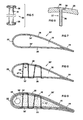
- FIG 1 shows a sectional view of a prior art hollow CMC airfoil formed with walls made of a ceramic fabric infused with a ceramic matrix.
- the airfoil has a leading edge 22, a trailing edge 24, a pressure wall 26, a suction wall 28, and an interior space 30. It may also have an insulative outer layer 42.
- High-temperature insulation for ceramic matrix composites has been described in U.S. patent 6,197,424 , incorporated by reference herein, which issued on March 6, 2001, and is commonly assigned with the present invention.
- FIG 2 shows a CMC airfoil 20 with holes 32 and 34 formed in the pressure and suction walls 26, 28.
- the holes 32, 34 may be formed by any known technique, for example laser drilling, after drying or partially to fully curing the CMC walls 26, 28.
- FIG 3 shows a bundle of ceramic fibers 36 passing through the holes 32 and 34.
- FIG 4 shows the bundle of ceramic fibers 36 flared 38 at both ends against outer surfaces of the walls 26, 28. The bundle of ceramic fibers 36 is now interconnected between the opposed walls 26 and 28 forming a stitch 37 that resists the walls 26, 28 from being flexed outward under pressure from cooling air in the interior space 30.
- the bundle of ceramic fibers may have a cross section with an aspect ratio of less than 6:1, or less than 4:1, or less than 2:1, such as a generally circular cross section, in order to provide sufficient strength to avoid structural failure while still avoiding excessive thermal expansion stress as may be experienced with prior art spars.
- the bundle of fibers may include ceramic fibers that are oriented generally along a longitudinal axis of the bundle (i.e. along an axis between the opposed walls), and/or the fibers may be woven in any desired pattern.
- An insulating outer layer 42 may be applied on the airfoil 20 after stitching.
- FIG 5 shows an enlarged view of a bundle of ceramic fibers 36 in the form of a tube 44 with flairs 38.
- Commercially available braided tubes of ceramic fiber may be cut to length, infused with a fluid ceramic matrix, inserted through holes 32, 34 formed in the airfoil walls 26, 28, flared 38 on each end, dried, and fired.
- FIG 6 shows an enlarged partial section of a suction wall 28 with a bundle of ceramic fibers 36 flared 38 in a countersunk area 39 in the outer surface of the suction wall 28.
- the flare 38 may be smoothed flush with the outer surface of the suction wall 28.
- a corresponding countersink may be provided in the pressure wall 26 at the other end of the bundle of ceramic fibers 36.
- FIG 7 shows an embodiment of an airfoil 20' according to the invention with a plurality of holes 32', 34' formed in opposed walls 26, 28.
- FIG 8 shows a bundle of ceramic fibers 36' continuously threaded through the holes 32', 34' to form a plurality of stitches 37.
- FIG 9 shows a ceramic core 46 that may be poured or injected into the interior space 30, either before or after stitching. If the core 46 is applied after stitching, it flows around and encases the stitches 37 as shown. If the core 46 is applied before stitching, it is dried, and may be partially to fully cured. Then it may be laser drilled along with each pair of holes 32', 34' creating tunnels (not shown) through the core 46 for the stitches 37. A fugitive material (not shown) may be applied in a pattern in the interior space 30 before pouring or injecting the core 46 to create cooling air channels 48 in the core. Examples of this type of core are shown in U.S.
- Tributary channels may branch from the main channel 48, pass along the inside surface of the walls 22 - 28 between the stitches 37, and have exit holes on at least one of the walls 22, 26, 28.
- a fugitive material may be used to create channels through the core 46 for subsequently receiving a stitching element 37.
- An insulating outer layer 42 may be applied on the airfoil 20' after stitching.
- FIG 10 shows an embodiment of an airfoil 20" with bi-directional stitching with a bundle of ceramic fibers 36" to provide a plurality of crossing stitches 37.
- the stitch holes 32", 34" may be offset along the length dimension of the airfoil (not shown), so that the stitches 37 do not touch each other.
- the airfoil may be formed and only dried, or it may be partially or fully cured prior to inserting the stitching element(s). Then ceramic fiber bundles 36 or tubes 44 may be stitched into the airfoil 20 prior to or after ceramic matrix infusion.
- the ceramic matrix bundles 36 or tubes 44 may be infused and/or cured along with the airfoil or they may be processed separately or only partially together.
- Possible firing sequences may include firing the CMC airfoil 20 prior to stitching to preshrink the walls 22-28.
- the stitching 37 may be applied and fired. This results in a pre-tensioning of the cured stitching 37 that preloads the walls 22-28 in compression, further increasing its resistance to internal pressure.
- drying and firing sequences for the airfoil walls 22, 26, 28, the stitches 37 and the internal core 46 may be selected to facilitate manufacturing and/or to control relative shrinkage and pre-loading among these elements.
- the invention may be applied to both oxide and non-oxide materials, and the material used to form the stitch may be the same as or different than the material used to form the airfoil walls.
- the stitch material may be selected considering its coefficient of thermal expansion, among other properties, in order to affect the relative amount of thermal expansion between the stitch and the airfoil walls during various phases of operation of the article.
- the stitch may be formed of a CMC material or a metallic material, such as tungsten or other refractory metal or a superalloy material including oxide dispersion strengthened alloys, in various embodiments.
- This invention may be applied to hollow articles other than airfoils where resistance to a ballooning force and additional stiffness are desired.
- the stitches may be distributed evenly across an airfoil chord, or they may be placed strategically in locations that provide the most advantageous reduction in critical stresses or that reduce or eliminate mechanical interference for other internal structures.
- a stitch is located just forward of a critically stressed trailing edge of an airfoil, or proximate an unbonded region between an airfoil wall 26, 28 and an internal core 46 in order to reinforce an edge of a bonded region. Accordingly, it is intended that the invention be limited only by the appended claims.
Landscapes
- Engineering & Computer Science (AREA)
- Chemical & Material Sciences (AREA)
- Mechanical Engineering (AREA)
- General Engineering & Computer Science (AREA)
- Materials Engineering (AREA)
- Ceramic Engineering (AREA)
- Composite Materials (AREA)
- Architecture (AREA)
- Turbine Rotor Nozzle Sealing (AREA)
Abstract
Description
- The invention relates to ceramic matrix composite (CMC) fabrication technology for airfoils that are internally cooled with compressed air, such as turbine blades and vanes in gas turbine engines.
- Design requirements for internally cooled airfoils necessitate a positive pressure differential between the internal cooling air and the external hot gas environment to prevent hot gas intrusion into the airfoil in the event of an airfoil wall breach. CMC airfoils with hollow cores in gas turbines are particularly susceptible to wall bending loads associated with such pressure differentials due to the anisotropic strength behavior of CMC material. For laminate CMC constructions, the through-thickness direction has about 5% of the strength of the in-plane or fiber-direction strengths. Internal cooling air pressure causes high interlaminar tensile stresses in a hollow CMC airfoil, with maximum stress concentrations typically occurring at the inner radius of the trailing edge region. The inner radius of the leading edge region is also subject to stress concentrations.
- This problem is accentuated in large airfoils with long chord length, such as those used in large land-based gas turbines. A longer internal chamber size results in increased bending moments on the walls of the airfoil, resulting in higher stresses for a given inner/outer pressure differential.
- The most common method of reducing these stresses in metal turbine vanes is to provide internal metal spars that run the full or partial radial length of the airfoil. However this is not fully satisfactory for CMC airfoils, due to manufacturing constraints and also due to thermal radial expansion stress that builds between the hot airfoil skin and the cooler spars. Therefore, the present inventors have recognized that better methods are needed for reducing bending stresses in hot CMC airfoil walls resulting from internal cooling pressurization.
- The invention is explained in following description in view of the drawings that show:
- FIG. 1 is a sectional view of a prior art CMC airfoil with a hollow interior and an insulating outer layer.
- FIG. 2 is a sectional view of a CMC airfoil according to one embodiment of the invention after forming walls and drilling holes to receive a CMC stitch.
- FIG. 3 is a view as in FIG 2 after passing a bundle of ceramic fibers through holes in opposed walls of the airfoil.
- FIG. 4 is a view as in FIG 3 after flaring the bundle of ceramic fibers at both ends for anchoring, and then adding an insulating outer layer on the airfoil walls, thus forming a hidden stitch.
- FIG. 5 is an enlarged perspective view of a CMC tube with flared ends.
- FIG. 6 is an enlarged partial sectional view of an end of a bundle of ceramic fibers flared within a countersunk area in an outer surface of an airfoil wall for flush anchoring of the stitch.
- FIG. 7 illustrates a preparation step as in FIG 2 in an embodiment with a plurality of holes in the walls for multiple stitches with a continuous bundle of ceramic fibers.
- FIG. 8 is a view as in FIG 7 after stitching.
- FIG. 9 is a view as in FIG 8 after adding an internal core material and an insulating outer layer on the airfoil walls, covering the stitches.
- FIG. 10 illustrates an embodiment with bi-directional stitching.
- FIG 1 shows a sectional view of a prior art hollow CMC airfoil formed with walls made of a ceramic fabric infused with a ceramic matrix. The airfoil has a leading
edge 22, atrailing edge 24, apressure wall 26, asuction wall 28, and aninterior space 30. It may also have an insulativeouter layer 42. High-temperature insulation for ceramic matrix composites has been described inU.S. patent 6,197,424 , incorporated by reference herein, which issued on March 6, 2001, and is commonly assigned with the present invention. - FIG 2 shows a
CMC airfoil 20 withholes suction walls holes CMC walls ceramic fibers 36 passing through theholes ceramic fibers 36 flared 38 at both ends against outer surfaces of thewalls ceramic fibers 36 is now interconnected between theopposed walls stitch 37 that resists thewalls interior space 30. The bundle of ceramic fibers may have a cross section with an aspect ratio of less than 6:1, or less than 4:1, or less than 2:1, such as a generally circular cross section, in order to provide sufficient strength to avoid structural failure while still avoiding excessive thermal expansion stress as may be experienced with prior art spars. The bundle of fibers may include ceramic fibers that are oriented generally along a longitudinal axis of the bundle (i.e. along an axis between the opposed walls), and/or the fibers may be woven in any desired pattern. An insulatingouter layer 42 may be applied on theairfoil 20 after stitching. - FIG 5 shows an enlarged view of a bundle of
ceramic fibers 36 in the form of atube 44 withflairs 38. Commercially available braided tubes of ceramic fiber may be cut to length, infused with a fluid ceramic matrix, inserted throughholes airfoil walls - FIG 6 shows an enlarged partial section of a
suction wall 28 with a bundle ofceramic fibers 36 flared 38 in acountersunk area 39 in the outer surface of thesuction wall 28. Theflare 38 may be smoothed flush with the outer surface of thesuction wall 28. A corresponding countersink may be provided in thepressure wall 26 at the other end of the bundle ofceramic fibers 36. - FIG 7 shows an embodiment of an airfoil 20' according to the invention with a plurality of holes 32', 34' formed in
opposed walls stitches 37. - FIG 9 shows a
ceramic core 46 that may be poured or injected into theinterior space 30, either before or after stitching. If thecore 46 is applied after stitching, it flows around and encases thestitches 37 as shown. If thecore 46 is applied before stitching, it is dried, and may be partially to fully cured. Then it may be laser drilled along with each pair of holes 32', 34' creating tunnels (not shown) through thecore 46 for thestitches 37. A fugitive material (not shown) may be applied in a pattern in theinterior space 30 before pouring or injecting thecore 46 to createcooling air channels 48 in the core. Examples of this type of core are shown inU.S. patent 6,709,230 , incorporated by reference herein, which issued on March 23, 2004, and is commonly assigned with the present invention. Only amain cooling channel 48 is shown here. Tributary channels (not shown) may branch from themain channel 48, pass along the inside surface of the walls 22 - 28 between thestitches 37, and have exit holes on at least one of thewalls core 46 for subsequently receiving astitching element 37. An insulatingouter layer 42 may be applied on the airfoil 20' after stitching. - FIG 10 shows an embodiment of an
airfoil 20" with bi-directional stitching with a bundle ofceramic fibers 36" to provide a plurality ofcrossing stitches 37. Thestitch holes 32", 34" may be offset along the length dimension of the airfoil (not shown), so that thestitches 37 do not touch each other. - Variations on the processing steps are possible. For example, the airfoil may be formed and only dried, or it may be partially or fully cured prior to inserting the stitching element(s). Then
ceramic fiber bundles 36 ortubes 44 may be stitched into theairfoil 20 prior to or after ceramic matrix infusion. Theceramic matrix bundles 36 ortubes 44 may be infused and/or cured along with the airfoil or they may be processed separately or only partially together. Possible firing sequences may include firing theCMC airfoil 20 prior to stitching to preshrink the walls 22-28. Then thestitching 37 may be applied and fired. This results in a pre-tensioning of the curedstitching 37 that preloads the walls 22-28 in compression, further increasing its resistance to internal pressure. Similarly, drying and firing sequences for theairfoil walls stitches 37 and theinternal core 46 may be selected to facilitate manufacturing and/or to control relative shrinkage and pre-loading among these elements. - While various embodiments of the present invention have been shown and described herein, it will be obvious that such embodiments are provided by way of example only. Numerous variations, changes and substitutions may be made without departing from the invention herein. For example, the invention may be applied to both oxide and non-oxide materials, and the material used to form the stitch may be the same as or different than the material used to form the airfoil walls. The stitch material may be selected considering its coefficient of thermal expansion, among other properties, in order to affect the relative amount of thermal expansion between the stitch and the airfoil walls during various phases of operation of the article. The stitch may be formed of a CMC material or a metallic material, such as tungsten or other refractory metal or a superalloy material including oxide dispersion strengthened alloys, in various embodiments. This invention may be applied to hollow articles other than airfoils where resistance to a ballooning force and additional stiffness are desired. The stitches may be distributed evenly across an airfoil chord, or they may be placed strategically in locations that provide the most advantageous reduction in critical stresses or that reduce or eliminate mechanical interference for other internal structures. In one embodiment a stitch is located just forward of a critically stressed trailing edge of an airfoil, or proximate an unbonded region between an
airfoil wall internal core 46 in order to reinforce an edge of a bonded region. Accordingly, it is intended that the invention be limited only by the appended claims.
Claims (27)
- A method of forming a CMC airfoil, comprising:forming with a CMC material a leading edge, a trailing edge, a pressure wall between the leading and trailing edges, and a suction wall between the leading and trailing edges; andinterconnecting a CMC stitch between the pressure and suction walls.
- A method as in claim 1 wherein the interconnecting step comprises:forming a hole in the pressure wall and forming a generally opposed hole in the suction wall; andpassing a bundle of ceramic fibers through the holes to form a stitch of ceramic fibers between the pressure and suction walls.
- A method as in claim 1, further comprising forming the CMC stitch with a material different than the CMC material used to form the leading and trailing edges and the pressure and suction walls.
- A method as in claim 2, wherein the forming step comprises impregnating CMC fabric with a first ceramic matrix, shaping the impregnated fabric to form the leading and trailing edges and the pressure and suction walls, and drying the impregnated fabric prior to the hole forming step; wherein the passing step further comprises infusing the ceramic fibers with a second ceramic matrix; and further comprising curing the stitched walls and the stitch together after the passing step.
- A method as in claim 4, further comprising at least partially curing the impregnated fabric prior to curing the stitched walls and the stitch together in order to generate a preload in the stitch due to differential curing shrinkage.
- A method as in claim 2, wherein a plurality of holes are formed in the pressure and suction walls, and the bundle of ceramic fibers is continuously woven through the plurality of holes to form a plurality of stitches of ceramic fibers between the pressure and suction walls.
- A method as in claim 2, further comprising after the passing step:filling an interior space between the pressure and suction walls with a flowable ceramic core material; andcuring the airfoil, the stitch, and the core material together.
- A method as in claim 2, further comprising;impregnating the bundle of ceramic fibers with a ceramic matrix;anchoring the stitch of ceramic fibers to the pressure and suction walls at each of the holes; andcuring the stitch of impregnated ceramic fibers to form a reinforcement between the pressure and suction walls to restrain outward flexing of the pressure and suction walls.
- A method as in claim 8, wherein the CMC airfoil is at least partly cured before the anchoring step, and the stitch of impregnated ceramic fibers is cured after the anchoring step, such that a curing shrinkage of the CMC stitch results in a pre-tensioning of the CMC stitch between the pressure and suction walls of the airfoil.
- A method as in claim 8, wherein the bundle of ceramic fibers comprises ceramic fibers oriented generally along a longitudinal axis of the bundle of ceramic fibers.
- A method as in claim 8, wherein the bundle of ceramic fibers comprises a tube of ceramic fibers comprising first and second ends, and wherein the anchoring step comprises flaring each respective end of the tube of ceramic fibers against a respective outer surface of the pressure and suction walls proximate each of the respective holes.
- A method as in claim 8, further comprising forming a countersunk area around each of the holes on an outer surface of the pressure and suction walls prior to the passing step, and wherein the anchoring step comprises flaring each respective end of the bundle of ceramic fibers against the respective countersunk areas.
- A method as in claim 8, wherein the cured stitch of ceramic fibers has a cross sectional aspect ratio of less than 2:1.
- A method as in claim 8, wherein the cured stitch has a generally circular cross sectional shape.
- A CMC airfoil with an internal stitch formed by the method of claim 2.
- A CMC airfoil comprising:a first CMC wall and a second CMC wall spaced apart from each other to define an interior space; anda stitch interconnected between the first CMC wall and the second CMC wall.
- A CMC airfoil as in claim 16, wherein the stitch comprises a bundle of ceramic fibers oriented generally along a longitudinal axis of the stitch, wherein the bundle of ceramic fibers is impregnated with a ceramic matrix and has a cross sectional aspect ratio of less than 2:1.
- A CMC airfoil as in claim 16, wherein the stitch comprises a braided tube of ceramic fibers impregnated with a ceramic matrix, and wherein the braided tube is flared at each end against a surface of the respective wall.
- A CMC airfoil as in claim 18, further comprising a countersunk area formed in each respective wall, and the braided tube being flared at each respective end against the respective countersunk area.
- A CMC airfoil as in claim 16, wherein the stitch is pre-stressed in tension between the walls.
- A CMC airfoil as in claim 16, wherein the stitch is passed through a first hole in the first wall and a second hole in the second wall.
- A CMC airfoil as in claim 16, further comprising a plurality of stitches formed by passing a bundle of ceramic fibers continuously and alternately through a first and a second plurality of holes in the first and second walls respectively.
- A CMC airfoil as in claim 16, further comprising a ceramic core disposed in the interior space and encasing the stitch.
- A CMC airfoil as in claim 16, further comprising a flare at each opposed end of the stitch disposed against a respective surface of the respective wall; and
a layer of ceramic insulating material disposed over each respective wall and its respective flare. - A CMC airfoil as in claim 16, wherein the stitch comprises a CMC material.
- A CMC airfoil as in claim 16, wherein the stitch comprises a metallic material.
- A CMC member comprising:a first CMC wall and a second CMC wall spaced apart from each other to define an interior space subjected to a ballooning force; anda CMC stitch interconnected between the first CMC wall and the second CMC wall.
Applications Claiming Priority (1)
| Application Number | Priority Date | Filing Date | Title |
|---|---|---|---|
| US11/494,176 US7600978B2 (en) | 2006-07-27 | 2006-07-27 | Hollow CMC airfoil with internal stitch |
Publications (3)
| Publication Number | Publication Date |
|---|---|
| EP1884623A2 true EP1884623A2 (en) | 2008-02-06 |
| EP1884623A3 EP1884623A3 (en) | 2011-06-01 |
| EP1884623B1 EP1884623B1 (en) | 2016-12-14 |
Family
ID=38645654
Family Applications (1)
| Application Number | Title | Priority Date | Filing Date |
|---|---|---|---|
| EP07004422.7A Ceased EP1884623B1 (en) | 2006-07-27 | 2007-03-03 | Hollow CMC airfoil with internal stitch |
Country Status (2)
| Country | Link |
|---|---|
| US (1) | US7600978B2 (en) |
| EP (1) | EP1884623B1 (en) |
Cited By (7)
| Publication number | Priority date | Publication date | Assignee | Title |
|---|---|---|---|---|
| GB2510218A (en) * | 2012-10-22 | 2014-07-30 | Snecma | Turbine blade formed by bending a sheet of CMC |
| WO2016184475A1 (en) * | 2015-05-20 | 2016-11-24 | Bladena Aps | A wind turbine and a wind turbine blade |
| CN107034444A (en) * | 2015-10-29 | 2017-08-11 | 通用电气公司 | The technique of ceramic matrix composite component and manufacture ceramic matrix composite component |
| WO2017196298A1 (en) * | 2016-05-10 | 2017-11-16 | Siemens Aktiengesellschaft | Ceramic component for combustion turbine engines |
| CN107577874A (en) * | 2017-09-06 | 2018-01-12 | 厦门大学 | A Method for Determining Design Shrinkage Rate of Precision Casting Mold for Hollow Turbine Blades |
| US10018054B2 (en) | 2015-10-23 | 2018-07-10 | General Electric Company | Fabrication of gas turbine engine components using multiple processing steps |
| FR3082877A1 (en) * | 2018-06-21 | 2019-12-27 | Safran Aircraft Engines | BLADE WITH HYBRID STRUCTURE FOR TURBOMACHINE |
Families Citing this family (50)
| Publication number | Priority date | Publication date | Assignee | Title |
|---|---|---|---|---|
| US8137611B2 (en) * | 2005-03-17 | 2012-03-20 | Siemens Energy, Inc. | Processing method for solid core ceramic matrix composite airfoil |
| US7785076B2 (en) * | 2005-08-30 | 2010-08-31 | Siemens Energy, Inc. | Refractory component with ceramic matrix composite skeleton |
| GB2450935B (en) * | 2007-07-13 | 2009-06-03 | Rolls Royce Plc | Component with internal damping |
| GB2450934B (en) * | 2007-07-13 | 2009-10-07 | Rolls Royce Plc | A Component with a damping filler |
| EP2304228B1 (en) * | 2008-06-24 | 2012-02-22 | Danmarks Tekniske Universitet | A reinforced wind turbine blade |
| US8357323B2 (en) * | 2008-07-16 | 2013-01-22 | Siemens Energy, Inc. | Ceramic matrix composite wall with post laminate stitching |
| GB2462102B (en) * | 2008-07-24 | 2010-06-16 | Rolls Royce Plc | An aerofoil sub-assembly, an aerofoil and a method of making an aerofoil |
| US8033790B2 (en) * | 2008-09-26 | 2011-10-11 | Siemens Energy, Inc. | Multiple piece turbine engine airfoil with a structural spar |
| US8382436B2 (en) * | 2009-01-06 | 2013-02-26 | General Electric Company | Non-integral turbine blade platforms and systems |
| GB0901235D0 (en) * | 2009-01-27 | 2009-03-11 | Rolls Royce Plc | An article with a filler |
| US8262345B2 (en) | 2009-02-06 | 2012-09-11 | General Electric Company | Ceramic matrix composite turbine engine |
| GB0907004D0 (en) * | 2009-04-24 | 2009-06-03 | Rolls Royce Plc | A method of manufacturing a component comprising an internal structure |
| GB0911416D0 (en) * | 2009-07-02 | 2009-08-12 | Rolls Royce Plc | A method of forming an internal structure within a hollow component |
| GB0916687D0 (en) * | 2009-09-23 | 2009-11-04 | Rolls Royce Plc | An aerofoil structure |
| US20110206522A1 (en) * | 2010-02-24 | 2011-08-25 | Ioannis Alvanos | Rotating airfoil fabrication utilizing cmc |
| GB201009216D0 (en) | 2010-06-02 | 2010-07-21 | Rolls Royce Plc | Rotationally balancing a rotating part |
| FR2963949A1 (en) * | 2010-08-18 | 2012-02-24 | Aircelle Sa | BEAM PARTICULARLY FOR THRUST INVERTER WITH GRILLS |
| US8347636B2 (en) | 2010-09-24 | 2013-01-08 | General Electric Company | Turbomachine including a ceramic matrix composite (CMC) bridge |
| GB2485831B (en) | 2010-11-26 | 2012-11-21 | Rolls Royce Plc | A method of manufacturing a component |
| FR2984848B1 (en) * | 2011-12-23 | 2016-01-15 | Ratier Figeac Soc | PROPELLER BLADE WITH HOUSINGS AND REINFORCING LENGTHS AND PROPELLER COMPRISING AT LEAST ONE SUCH BLADE |
| US9664052B2 (en) * | 2012-10-03 | 2017-05-30 | General Electric Company | Turbine component, turbine blade, and turbine component fabrication process |
| US9435209B2 (en) | 2012-10-25 | 2016-09-06 | General Electric Company | Turbomachine blade reinforcement |
| US10487675B2 (en) | 2013-02-18 | 2019-11-26 | United Technologies Corporation | Stress mitigation feature for composite airfoil leading edge |
| EP2946078B1 (en) | 2013-03-03 | 2019-02-20 | Rolls-Royce North American Technologies, Inc. | Gas turbine engine component having foam core and composite skin with cooling slot |
| EP2971584B1 (en) | 2013-03-11 | 2019-08-28 | Rolls-Royce Corporation | Compliant intermediate component of a gas turbine engine and method of assembling this component |
| FR3012064B1 (en) * | 2013-10-23 | 2016-07-29 | Snecma | FIBROUS PREFORMS FOR TURBOMACHINE HOLLOW DREAM |
| US10563522B2 (en) * | 2014-09-22 | 2020-02-18 | Rolls-Royce North American Technologies Inc. | Composite airfoil for a gas turbine engine |
| EP3048254B1 (en) | 2015-01-22 | 2017-12-27 | Rolls-Royce Corporation | Vane assembly for a gas turbine engine |
| EP3059390B1 (en) * | 2015-02-18 | 2020-03-04 | Rolls-Royce Corporation | Vane assembly for a gas turbine engine, airfoil and method of making |
| US10309257B2 (en) | 2015-03-02 | 2019-06-04 | Rolls-Royce North American Technologies Inc. | Turbine assembly with load pads |
| US10408084B2 (en) | 2015-03-02 | 2019-09-10 | Rolls-Royce North American Technologies Inc. | Vane assembly for a gas turbine engine |
| US9840184B2 (en) * | 2015-04-13 | 2017-12-12 | Charles Herbert Chadwell, IV | Strap retaining apparatus |
| FR3041684B1 (en) * | 2015-09-28 | 2021-12-10 | Snecma | DAWN INCLUDING AN ATTACK EDGE SHIELD AND PROCESS FOR MANUFACTURING THE DAWN |
| US10207471B2 (en) * | 2016-05-04 | 2019-02-19 | General Electric Company | Perforated ceramic matrix composite ply, ceramic matrix composite article, and method for forming ceramic matrix composite article |
| EP3318484B1 (en) | 2016-11-08 | 2020-07-08 | Ratier-Figeac SAS | Reinforced propeller blade and spar |
| EP3318483B1 (en) | 2016-11-08 | 2020-12-30 | Ratier-Figeac SAS | Reinforced propeller blade |
| EP3321178B1 (en) | 2016-11-10 | 2020-02-26 | Ratier-Figeac SAS | Reinforced propeller blade and spar |
| US10731495B2 (en) * | 2016-11-17 | 2020-08-04 | Raytheon Technologies Corporation | Airfoil with panel having perimeter seal |
| US10443410B2 (en) * | 2017-06-16 | 2019-10-15 | General Electric Company | Ceramic matrix composite (CMC) hollow blade and method of forming CMC hollow blade |
| US10487672B2 (en) * | 2017-11-20 | 2019-11-26 | Rolls-Royce Corporation | Airfoil for a gas turbine engine having insulating materials |
| US10774005B2 (en) | 2018-01-05 | 2020-09-15 | Raytheon Technologies Corporation | Needled ceramic matrix composite cooling passages |
| US11125087B2 (en) | 2018-01-05 | 2021-09-21 | Raytheon Technologies Corporation | Needled ceramic matrix composite cooling passages |
| US11261741B2 (en) * | 2019-11-08 | 2022-03-01 | Raytheon Technologies Corporation | Ceramic airfoil trailing end configuration |
| US11773723B2 (en) * | 2019-11-15 | 2023-10-03 | Rtx Corporation | Airfoil rib with thermal conductance element |
| US20210188717A1 (en) * | 2019-12-20 | 2021-06-24 | United Technologies Corporation | Reinforced ceramic matrix composite and method of manufacture |
| CN113929482B (en) * | 2021-11-19 | 2022-07-19 | 西北工业大学 | Ceramic matrix composite turbine guide vane and preparation method thereof |
| US12196095B2 (en) * | 2022-11-29 | 2025-01-14 | Rtx Corporation | Gas turbine engine component having an airfoil with internal cross-ribs |
| US11920495B1 (en) | 2023-01-20 | 2024-03-05 | Rtx Corporation | Airfoil with thick wishbone fiber structure |
| US12565033B2 (en) * | 2023-05-12 | 2026-03-03 | Rtx Corporation | Ceramic matrix composite sandwich structure reinforced with z-tows |
| US12535008B2 (en) * | 2023-10-03 | 2026-01-27 | General Electric Company | Airfoil assembly having a composite core |
Family Cites Families (16)
| Publication number | Priority date | Publication date | Assignee | Title |
|---|---|---|---|---|
| GB1320539A (en) * | 1970-12-10 | 1973-06-13 | Secr Defence | Aerofoil-shaped blade for a fluid flow machine |
| GB1500776A (en) * | 1976-04-08 | 1978-02-08 | Rolls Royce | Fibre reinforced composite structures |
| GB2230258B (en) * | 1989-04-14 | 1993-10-20 | Gen Electric | Consolidated member and method and preform for making |
| CA2042218A1 (en) * | 1990-07-20 | 1992-01-21 | Jan C. Schilling | Composite airfoil with increased shear capability |
| FR2684719B1 (en) * | 1991-12-04 | 1994-02-11 | Snecma | BLADE OF TURBOMACHINE COMPRISING PLASTS OF COMPOSITE MATERIAL. |
| GB2270310B (en) * | 1992-09-02 | 1995-11-08 | Rolls Royce Plc | A method of manufacturing a hollow silicon carbide fibre reinforced silicon carbide matrix component |
| DE4411679C1 (en) * | 1994-04-05 | 1994-12-01 | Mtu Muenchen Gmbh | Blade of fibre-composite construction having a protective profile |
| US5630700A (en) * | 1996-04-26 | 1997-05-20 | General Electric Company | Floating vane turbine nozzle |
| US6431837B1 (en) * | 1999-06-01 | 2002-08-13 | Alexander Velicki | Stitched composite fan blade |
| US6398501B1 (en) * | 1999-09-17 | 2002-06-04 | General Electric Company | Apparatus for reducing thermal stress in turbine airfoils |
| US6451416B1 (en) * | 1999-11-19 | 2002-09-17 | United Technologies Corporation | Hybrid monolithic ceramic and ceramic matrix composite airfoil and method for making the same |
| US6325593B1 (en) * | 2000-02-18 | 2001-12-04 | General Electric Company | Ceramic turbine airfoils with cooled trailing edge blocks |
| US6514046B1 (en) * | 2000-09-29 | 2003-02-04 | Siemens Westinghouse Power Corporation | Ceramic composite vane with metallic substructure |
| US6709230B2 (en) * | 2002-05-31 | 2004-03-23 | Siemens Westinghouse Power Corporation | Ceramic matrix composite gas turbine vane |
| US7093359B2 (en) * | 2002-09-17 | 2006-08-22 | Siemens Westinghouse Power Corporation | Composite structure formed by CMC-on-insulation process |
| US7247003B2 (en) * | 2004-12-02 | 2007-07-24 | Siemens Power Generation, Inc. | Stacked lamellate assembly |
-
2006
- 2006-07-27 US US11/494,176 patent/US7600978B2/en not_active Expired - Fee Related
-
2007
- 2007-03-03 EP EP07004422.7A patent/EP1884623B1/en not_active Ceased
Cited By (15)
| Publication number | Priority date | Publication date | Assignee | Title |
|---|---|---|---|---|
| GB2510218B (en) * | 2012-10-22 | 2019-09-11 | Snecma | High-pressure turbine blades made of ceramic matrix composites |
| US9482104B2 (en) | 2012-10-22 | 2016-11-01 | Snecma | High-pressure turbine blades made of ceramic matrix composites |
| GB2510218A (en) * | 2012-10-22 | 2014-07-30 | Snecma | Turbine blade formed by bending a sheet of CMC |
| WO2016184475A1 (en) * | 2015-05-20 | 2016-11-24 | Bladena Aps | A wind turbine and a wind turbine blade |
| CN107873070B (en) * | 2015-05-20 | 2020-11-03 | 布拉德纳公司 | Wind turbine and wind turbine blade |
| US10590910B2 (en) | 2015-05-20 | 2020-03-17 | Bladena Aps | Wind turbine and a wind turbine blade |
| CN107873070A (en) * | 2015-05-20 | 2018-04-03 | 布拉德纳公司 | Wind turbines and wind turbine blades |
| US10018054B2 (en) | 2015-10-23 | 2018-07-10 | General Electric Company | Fabrication of gas turbine engine components using multiple processing steps |
| CN107034444A (en) * | 2015-10-29 | 2017-08-11 | 通用电气公司 | The technique of ceramic matrix composite component and manufacture ceramic matrix composite component |
| CN107034444B (en) * | 2015-10-29 | 2021-07-13 | 通用电气公司 | Ceramic matrix composite components and process for making ceramic matrix composite components |
| CN109154196A (en) * | 2016-05-10 | 2019-01-04 | 西门子股份公司 | Ceramic components for combustion turbine engines |
| WO2017196298A1 (en) * | 2016-05-10 | 2017-11-16 | Siemens Aktiengesellschaft | Ceramic component for combustion turbine engines |
| CN107577874B (en) * | 2017-09-06 | 2019-07-19 | 厦门大学 | A Method for Determining Design Shrinkage Rate of Precision Casting Die for Hollow Turbine Blades |
| CN107577874A (en) * | 2017-09-06 | 2018-01-12 | 厦门大学 | A Method for Determining Design Shrinkage Rate of Precision Casting Mold for Hollow Turbine Blades |
| FR3082877A1 (en) * | 2018-06-21 | 2019-12-27 | Safran Aircraft Engines | BLADE WITH HYBRID STRUCTURE FOR TURBOMACHINE |
Also Published As
| Publication number | Publication date |
|---|---|
| US7600978B2 (en) | 2009-10-13 |
| US20080025846A1 (en) | 2008-01-31 |
| EP1884623A3 (en) | 2011-06-01 |
| EP1884623B1 (en) | 2016-12-14 |
Similar Documents
| Publication | Publication Date | Title |
|---|---|---|
| US7600978B2 (en) | Hollow CMC airfoil with internal stitch | |
| US10850456B2 (en) | Method of fabricating an airfoil element out of composite material and having metal reinforcement fastened by riveting | |
| EP1768893B1 (en) | Ceramic matrix composite airfoil trailing edge arrangement | |
| US6746755B2 (en) | Ceramic matrix composite structure having integral cooling passages and method of manufacture | |
| JP6557223B2 (en) | Composite propeller blade for aircraft | |
| US9664053B2 (en) | Integral textile structure for 3-D CMC turbine airfoils | |
| CN106687662B (en) | Method of manufacturing turbine engine blades made of composite material, resulting blades, and turbine engines comprising same | |
| US10584603B2 (en) | Composite material vane with integrated aerodynamic covering element and manufacturing method thereof | |
| CN107075958B (en) | Assembly of two parts assembled by mechanical anchoring elements, one part made of composite material | |
| US10480108B2 (en) | Ceramic matrix composite components reinforced for managing multi-axial stresses and methods for fabricating the same | |
| EP3075531A1 (en) | Sandwich arrangement with ceramic panels and ceramic felts | |
| US9550340B2 (en) | Composite material part comprising fixing means | |
| US20190145269A1 (en) | Ceramic component for combustion turbine engines | |
| CN112739530A (en) | Composite shell with integrated reinforcement | |
| JP2011527400A (en) | Stator blade for 3D composite blower | |
| US11753948B2 (en) | Woven fibrous preform for producing a composite part, especially a turbomachine blade | |
| CN108474148B (en) | Preform with integral gap filler | |
| JP2019500533A (en) | Method of manufacturing a composite part having a body integral with one or more platforms | |
| US9382647B2 (en) | Fibrous structure for a part made of a composite material and having a complex shape | |
| EP3415717B1 (en) | Ceramic matrix composite (cmc) hollow blade and method of forming such blade | |
| EP2543506B1 (en) | Layered composite component | |
| CN113601916A (en) | Multi-layer woven product | |
| CN115867521B (en) | Method for manufacturing nozzle blades from ceramic matrix composite materials | |
| CN116249827A (en) | Method for producing a composite material part with a lattice structure and corresponding part | |
| Marshall et al. | Integral textile structure for 3-D CMC turbine airfoils |
Legal Events
| Date | Code | Title | Description |
|---|---|---|---|
| PUAI | Public reference made under article 153(3) epc to a published international application that has entered the european phase |
Free format text: ORIGINAL CODE: 0009012 |
|
| AK | Designated contracting states |
Kind code of ref document: A2 Designated state(s): AT BE BG CH CY CZ DE DK EE ES FI FR GB GR HU IE IS IT LI LT LU LV MC MT NL PL PT RO SE SI SK TR |
|
| AX | Request for extension of the european patent |
Extension state: AL BA HR MK YU |
|
| PUAL | Search report despatched |
Free format text: ORIGINAL CODE: 0009013 |
|
| RAP1 | Party data changed (applicant data changed or rights of an application transferred) |
Owner name: SIEMENS ENERGY, INC. |
|
| AK | Designated contracting states |
Kind code of ref document: A3 Designated state(s): AT BE BG CH CY CZ DE DK EE ES FI FR GB GR HU IE IS IT LI LT LU LV MC MT NL PL PT RO SE SI SK TR |
|
| AX | Request for extension of the european patent |
Extension state: AL BA HR MK RS |
|
| 17P | Request for examination filed |
Effective date: 20111012 |
|
| AKX | Designation fees paid |
Designated state(s): DE FR GB IT |
|
| 17Q | First examination report despatched |
Effective date: 20150904 |
|
| GRAP | Despatch of communication of intention to grant a patent |
Free format text: ORIGINAL CODE: EPIDOSNIGR1 |
|
| INTG | Intention to grant announced |
Effective date: 20160714 |
|
| GRAS | Grant fee paid |
Free format text: ORIGINAL CODE: EPIDOSNIGR3 |
|
| STAA | Information on the status of an ep patent application or granted ep patent |
Free format text: STATUS: GRANT OF PATENT IS INTENDED |
|
| GRAA | (expected) grant |
Free format text: ORIGINAL CODE: 0009210 |
|
| STAA | Information on the status of an ep patent application or granted ep patent |
Free format text: STATUS: THE PATENT HAS BEEN GRANTED |
|
| AK | Designated contracting states |
Kind code of ref document: B1 Designated state(s): DE FR GB IT |
|
| REG | Reference to a national code |
Ref country code: GB Ref legal event code: FG4D |
|
| REG | Reference to a national code |
Ref country code: DE Ref legal event code: R096 Ref document number: 602007049103 Country of ref document: DE |
|
| REG | Reference to a national code |
Ref country code: FR Ref legal event code: PLFP Year of fee payment: 11 |
|
| PG25 | Lapsed in a contracting state [announced via postgrant information from national office to epo] |
Ref country code: IT Free format text: LAPSE BECAUSE OF FAILURE TO SUBMIT A TRANSLATION OF THE DESCRIPTION OR TO PAY THE FEE WITHIN THE PRESCRIBED TIME-LIMIT Effective date: 20161214 |
|
| REG | Reference to a national code |
Ref country code: DE Ref legal event code: R097 Ref document number: 602007049103 Country of ref document: DE |
|
| PLBE | No opposition filed within time limit |
Free format text: ORIGINAL CODE: 0009261 |
|
| STAA | Information on the status of an ep patent application or granted ep patent |
Free format text: STATUS: NO OPPOSITION FILED WITHIN TIME LIMIT |
|
| 26N | No opposition filed |
Effective date: 20170915 |
|
| REG | Reference to a national code |
Ref country code: FR Ref legal event code: PLFP Year of fee payment: 12 |
|
| PGFP | Annual fee paid to national office [announced via postgrant information from national office to epo] |
Ref country code: FR Payment date: 20190322 Year of fee payment: 13 Ref country code: GB Payment date: 20190313 Year of fee payment: 13 |
|
| PGFP | Annual fee paid to national office [announced via postgrant information from national office to epo] |
Ref country code: DE Payment date: 20190517 Year of fee payment: 13 |
|
| REG | Reference to a national code |
Ref country code: DE Ref legal event code: R119 Ref document number: 602007049103 Country of ref document: DE |
|
| PG25 | Lapsed in a contracting state [announced via postgrant information from national office to epo] |
Ref country code: FR Free format text: LAPSE BECAUSE OF NON-PAYMENT OF DUE FEES Effective date: 20200331 Ref country code: DE Free format text: LAPSE BECAUSE OF NON-PAYMENT OF DUE FEES Effective date: 20201001 |
|
| GBPC | Gb: european patent ceased through non-payment of renewal fee |
Effective date: 20200303 |
|
| PG25 | Lapsed in a contracting state [announced via postgrant information from national office to epo] |
Ref country code: GB Free format text: LAPSE BECAUSE OF NON-PAYMENT OF DUE FEES Effective date: 20200303 |