EP1884293B1 - Maskierungssystem zur Maskierung einer Zylinderbohrung - Google Patents
Maskierungssystem zur Maskierung einer Zylinderbohrung Download PDFInfo
- Publication number
- EP1884293B1 EP1884293B1 EP07109434A EP07109434A EP1884293B1 EP 1884293 B1 EP1884293 B1 EP 1884293B1 EP 07109434 A EP07109434 A EP 07109434A EP 07109434 A EP07109434 A EP 07109434A EP 1884293 B1 EP1884293 B1 EP 1884293B1
- Authority
- EP
- European Patent Office
- Prior art keywords
- masking
- cylinder
- accordance
- masking system
- previous
- Prior art date
- Legal status (The legal status is an assumption and is not a legal conclusion. Google has not performed a legal analysis and makes no representation as to the accuracy of the status listed.)
- Not-in-force
Links
- 230000000873 masking effect Effects 0.000 title claims description 91
- 238000000576 coating method Methods 0.000 claims description 46
- 239000011248 coating agent Substances 0.000 claims description 31
- 239000012530 fluid Substances 0.000 claims description 26
- 238000000034 method Methods 0.000 claims description 15
- 238000002485 combustion reaction Methods 0.000 claims description 13
- 238000011109 contamination Methods 0.000 claims description 7
- 238000001816 cooling Methods 0.000 claims description 6
- 238000010285 flame spraying Methods 0.000 claims description 4
- 238000005507 spraying Methods 0.000 claims description 3
- 238000007751 thermal spraying Methods 0.000 claims description 3
- 239000000203 mixture Substances 0.000 claims description 2
- 238000007750 plasma spraying Methods 0.000 claims description 2
- 229910052751 metal Inorganic materials 0.000 description 12
- 239000002184 metal Substances 0.000 description 12
- 239000000463 material Substances 0.000 description 10
- 239000007921 spray Substances 0.000 description 8
- 239000000758 substrate Substances 0.000 description 7
- 238000010276 construction Methods 0.000 description 5
- 239000007789 gas Substances 0.000 description 5
- 230000008021 deposition Effects 0.000 description 3
- 230000001105 regulatory effect Effects 0.000 description 3
- 239000007787 solid Substances 0.000 description 3
- XKRFYHLGVUSROY-UHFFFAOYSA-N Argon Chemical compound [Ar] XKRFYHLGVUSROY-UHFFFAOYSA-N 0.000 description 2
- IJGRMHOSHXDMSA-UHFFFAOYSA-N Atomic nitrogen Chemical compound N#N IJGRMHOSHXDMSA-UHFFFAOYSA-N 0.000 description 2
- XEEYBQQBJWHFJM-UHFFFAOYSA-N Iron Chemical compound [Fe] XEEYBQQBJWHFJM-UHFFFAOYSA-N 0.000 description 2
- 229910052782 aluminium Inorganic materials 0.000 description 2
- 230000032798 delamination Effects 0.000 description 2
- 230000000694 effects Effects 0.000 description 2
- 230000009931 harmful effect Effects 0.000 description 2
- 238000010438 heat treatment Methods 0.000 description 2
- 229910052749 magnesium Inorganic materials 0.000 description 2
- 239000011777 magnesium Substances 0.000 description 2
- 229910001092 metal group alloy Inorganic materials 0.000 description 2
- 238000013021 overheating Methods 0.000 description 2
- 230000002265 prevention Effects 0.000 description 2
- 229910001018 Cast iron Inorganic materials 0.000 description 1
- FYYHWMGAXLPEAU-UHFFFAOYSA-N Magnesium Chemical compound [Mg] FYYHWMGAXLPEAU-UHFFFAOYSA-N 0.000 description 1
- 238000009825 accumulation Methods 0.000 description 1
- 238000001994 activation Methods 0.000 description 1
- 229910045601 alloy Inorganic materials 0.000 description 1
- 239000000956 alloy Substances 0.000 description 1
- XAGFODPZIPBFFR-UHFFFAOYSA-N aluminium Chemical compound [Al] XAGFODPZIPBFFR-UHFFFAOYSA-N 0.000 description 1
- 229910052786 argon Inorganic materials 0.000 description 1
- 238000005422 blasting Methods 0.000 description 1
- 229910052593 corundum Inorganic materials 0.000 description 1
- 239000010431 corundum Substances 0.000 description 1
- 230000001419 dependent effect Effects 0.000 description 1
- 239000000428 dust Substances 0.000 description 1
- 239000001307 helium Substances 0.000 description 1
- 229910052734 helium Inorganic materials 0.000 description 1
- SWQJXJOGLNCZEY-UHFFFAOYSA-N helium atom Chemical compound [He] SWQJXJOGLNCZEY-UHFFFAOYSA-N 0.000 description 1
- 229910052742 iron Inorganic materials 0.000 description 1
- 238000004519 manufacturing process Methods 0.000 description 1
- 229910052757 nitrogen Inorganic materials 0.000 description 1
- 229910052756 noble gas Inorganic materials 0.000 description 1
- 239000002245 particle Substances 0.000 description 1
- 239000000843 powder Substances 0.000 description 1
- XLYOFNOQVPJJNP-UHFFFAOYSA-N water Substances O XLYOFNOQVPJJNP-UHFFFAOYSA-N 0.000 description 1
Images

Classifications
-
- C—CHEMISTRY; METALLURGY
- C23—COATING METALLIC MATERIAL; COATING MATERIAL WITH METALLIC MATERIAL; CHEMICAL SURFACE TREATMENT; DIFFUSION TREATMENT OF METALLIC MATERIAL; COATING BY VACUUM EVAPORATION, BY SPUTTERING, BY ION IMPLANTATION OR BY CHEMICAL VAPOUR DEPOSITION, IN GENERAL; INHIBITING CORROSION OF METALLIC MATERIAL OR INCRUSTATION IN GENERAL
- C23C—COATING METALLIC MATERIAL; COATING MATERIAL WITH METALLIC MATERIAL; SURFACE TREATMENT OF METALLIC MATERIAL BY DIFFUSION INTO THE SURFACE, BY CHEMICAL CONVERSION OR SUBSTITUTION; COATING BY VACUUM EVAPORATION, BY SPUTTERING, BY ION IMPLANTATION OR BY CHEMICAL VAPOUR DEPOSITION, IN GENERAL
- C23C4/00—Coating by spraying the coating material in the molten state, e.g. by flame, plasma or electric discharge
- C23C4/01—Selective coating, e.g. pattern coating, without pre-treatment of the material to be coated
-
- B—PERFORMING OPERATIONS; TRANSPORTING
- B05—SPRAYING OR ATOMISING IN GENERAL; APPLYING FLUENT MATERIALS TO SURFACES, IN GENERAL
- B05B—SPRAYING APPARATUS; ATOMISING APPARATUS; NOZZLES
- B05B12/00—Arrangements for controlling delivery; Arrangements for controlling the spray area
- B05B12/16—Arrangements for controlling delivery; Arrangements for controlling the spray area for controlling the spray area
- B05B12/18—Arrangements for controlling delivery; Arrangements for controlling the spray area for controlling the spray area using fluids, e.g. gas streams
-
- B—PERFORMING OPERATIONS; TRANSPORTING
- B05—SPRAYING OR ATOMISING IN GENERAL; APPLYING FLUENT MATERIALS TO SURFACES, IN GENERAL
- B05B—SPRAYING APPARATUS; ATOMISING APPARATUS; NOZZLES
- B05B12/00—Arrangements for controlling delivery; Arrangements for controlling the spray area
- B05B12/16—Arrangements for controlling delivery; Arrangements for controlling the spray area for controlling the spray area
- B05B12/20—Masking elements, i.e. elements defining uncoated areas on an object to be coated
-
- B—PERFORMING OPERATIONS; TRANSPORTING
- B05—SPRAYING OR ATOMISING IN GENERAL; APPLYING FLUENT MATERIALS TO SURFACES, IN GENERAL
- B05B—SPRAYING APPARATUS; ATOMISING APPARATUS; NOZZLES
- B05B12/00—Arrangements for controlling delivery; Arrangements for controlling the spray area
- B05B12/16—Arrangements for controlling delivery; Arrangements for controlling the spray area for controlling the spray area
- B05B12/20—Masking elements, i.e. elements defining uncoated areas on an object to be coated
- B05B12/26—Masking elements, i.e. elements defining uncoated areas on an object to be coated for masking cavities
-
- B—PERFORMING OPERATIONS; TRANSPORTING
- B05—SPRAYING OR ATOMISING IN GENERAL; APPLYING FLUENT MATERIALS TO SURFACES, IN GENERAL
- B05B—SPRAYING APPARATUS; ATOMISING APPARATUS; NOZZLES
- B05B7/00—Spraying apparatus for discharge of liquids or other fluent materials from two or more sources, e.g. of liquid and air, of powder and gas
- B05B7/16—Spraying apparatus for discharge of liquids or other fluent materials from two or more sources, e.g. of liquid and air, of powder and gas incorporating means for heating or cooling the material to be sprayed
- B05B7/20—Spraying apparatus for discharge of liquids or other fluent materials from two or more sources, e.g. of liquid and air, of powder and gas incorporating means for heating or cooling the material to be sprayed by flame or combustion
-
- B—PERFORMING OPERATIONS; TRANSPORTING
- B05—SPRAYING OR ATOMISING IN GENERAL; APPLYING FLUENT MATERIALS TO SURFACES, IN GENERAL
- B05B—SPRAYING APPARATUS; ATOMISING APPARATUS; NOZZLES
- B05B7/00—Spraying apparatus for discharge of liquids or other fluent materials from two or more sources, e.g. of liquid and air, of powder and gas
- B05B7/16—Spraying apparatus for discharge of liquids or other fluent materials from two or more sources, e.g. of liquid and air, of powder and gas incorporating means for heating or cooling the material to be sprayed
- B05B7/22—Spraying apparatus for discharge of liquids or other fluent materials from two or more sources, e.g. of liquid and air, of powder and gas incorporating means for heating or cooling the material to be sprayed electrically, magnetically or electromagnetically, e.g. by arc
Definitions
- the invention relates to a masking system for masking a cylinder bore of an internal combustion engine during a thermal coating process, as well as the use of a marking system according to the invention according to the preamble of the independent claim of the respective category.
- thermal coating of cylinder surfaces of internal combustion engines by various thermal spraying methods is state of the art nowadays and is widely used, in particular, but not only, in engines for motor vehicles of all kinds.
- the corresponding cylinder treads are activated by various methods prior to thermal coating, e.g. by corundum blasting, chilled cast iron, high pressure water jets or by other known activation processes.
- Substrates made of light metal alloys based on Al or Mg are most commonly used.
- V-type engines that is, engines having two parallel rows of cylinders, wherein the two longitudinal axes of two adjacent cylinder liners, each belonging to one of the two rows of cylinders, are inclined by a certain angle to each other, whereby the characteristic V-shape of the engine block of a V-shaped engine is formed.
- thermal coating involves the risk that, during coating of a cylinder wall of a cylinder bore of a first cylinder bank, on the cylinder wall of an adjacent cylinder of the second bank of cylinders, vapors, e.g. Metal vapors of the coating material, which are never completely avoided during thermal coating, are deposited. Due to the deposition of the metal vapors on the relatively cold walls on the cylinder wall of the cylinder of the second row of cylinders, this cylinder wall is contaminated in the second row of cylinders by the metal vapors, which, inter alia, has a negative effect on the adhesion of a later also applied to this cylinder coating , In addition, contamination by unmelted particles and overspray is to be feared.
- vapors e.g. Metal vapors of the coating material
- Another problem is the heating of the engine block by the thermal coating process. Since the difference in thermal expansion coefficient between the thermal spray layer and the substrate may be relatively high, a temperature of the substrate above 120 ° C, which is essentially a kind of mean engine block temperature, has a negative effect on the residual stress level of the layers and above 150 ° C, there is even the danger that the made of a light metal alloy component, so the engine block, a distortion of the material suffers and thus unusable.
- typical expansion coefficients of thermal spray coatings of iron-based alloys are, for example, about 11 ⁇ 10 -6 / ° C, while typical thermal expansion coefficients of aluminum-based substrates at about 23 ⁇ 10 -6 / ° C and magnesium-based substrates typically at 27x10 -6 / ° C.
- typical coefficients of thermal expansion of the substrates that is to say of the material from which the engine blocks are made, are more than twice the size of the thermal expansion coefficients of the sprayed-on thermal sprayed coatings on the order of magnitude.
- the EP 1 685 910 A1 discloses a device for applying a coating to an engine block, with which during the coating of a first cylinder bank to protect a second cylinder bank, a nozzle for sucking gas from the second cylinder bank is provided. However, here too, especially the cooling of the cylinder block is not sufficiently guaranteed.
- the object of the invention is therefore to provide a device with which the problems known from the prior art, in particular the thermal problems and the problems with the contamination by metal vapors, are avoided in the thermal coating of cylinder bores of internal combustion engines At the same time a high degree of automation can be achieved easily and inexpensively.
- the invention thus relates to a masking system for masking a cylinder bore of an internal combustion engine during a thermal coating process, comprising a masking body, which can be placed during the thermal coating process of a first cylinder of the internal combustion engine to cover a cylinder wall of a second cylinder in the cylinder bore of the second cylinder.
- the masking body is configured such that a flow gap of predeterminable width can be set to produce a flow of a fluid between the masking body and the cylinder wall of the second cylinder.
- the masking system comprises a masking body, which on the one hand substantially completely covers a cylinder wall of a cylinder bore which is not to be coated during the coating of another cylinder wall and which therefore covers it before the direct application of metal vapors originating from a coating jet which the other cylinder is coated protects. So prevents the cylinder wall not to be coated from being exposed directly or indirectly to the coating jet.
- the masking body is configured in such a way that a flow gap remains free between the masking body and the cylinder wall which is currently not to be coated, so that an air flow can be generated therein on the one hand causes cooling of the engine block in the covered cylinder bore and on the other hand prevents indirectly metal dust that spread in the interior of the engine block, reflected on the currently not to be coated cylinder wall.
- a closed pipe with a controlled flow gap between pipe and cylinder surface is introduced.
- a flow of air or other fluids is achieved, which cools the cylinder surface and at the same time prevents the deposition of metal vapors on this cylinder surface, since the flows or turbulence of the metal vapors can be effectively suppressed.
- a row of cylinders is preferably coated in each case.
- the cylinder row opposite it is protected by a masking system according to the invention such that, for example, a plasma jet of a rotating plasma spray device, which is guided in the axial direction during coating through the cylinder bore, which plasma jet at a lower reversal point in the region of the crankcase of the engine block to the opposite hole can reach, the cylinder walls not to be coated cylinder row reached.
- the masking body is a hollow masking body or a solid masking body, preferably a hollow masking cylinder or a solid masking cylinder.
- the masking body is preferably designed such that the flow gap has a width of 0.1 mm to 10 mm, preferably a width between 0.2 mm and 5 mm, in particular a width between 0.4 mm and 3 mm. This ensures at the same time that the flow gap is narrow enough so that a direct contamination of the cylinder wall of the cylinder protected by the masking body can be prevented and at the same time a sufficiently strong flow in the flow gap can be maintained, so that sufficient cooling can be achieved.
- a masking system comprises at least two masking bodies, so that at least two cylinders, preferably two adjacent cylinders, can be masked simultaneously, wherein in a particularly important practical embodiment the masking system comprises a predeterminable number of masking bodies and is designed such that a complete cylinder row of an internal combustion engine in V-construction is simultaneously maskable.
- the masking body preferably comprises a masking cover and the masking cover comprises in particular a channel which can be connected to the flow gap, in particular an outlet channel and / or an inlet channel for conveying the fluid.
- the channel may have openings, one or more of which may be provided in the masking cover over which the fluid, e.g. Air or another gas, for example by a suction device, which may be provided on the crankcase, is sucked, so that thereby the flow in the flow gap between masking body and cylinder wall can be produced.
- air or other gas may also be provided via the openings, several of which, for example, may be provided in the masking cover and e.g. may be arranged in the vicinity of an edge of the masking cover can be introduced under a predetermined pressure in the flow gap or sucked through the openings, wherein the flow direction of the fluid, depending on whether the fluid is injected under pressure into the openings or sucked out of these is directed either into the crankcase or out of this.
- the shape of the openings may vary depending on the requirement, e.g. circular openings, slot-shaped openings or openings of other suitable shape can be provided.
- a gas or a gas mixture in particular air and / or nitrogen and / or a noble gas, in particular argon and / or helium for generating the flow in the flow gap is particularly well suited.
- a suction means may be provided on the crankshaft space of the motor housing to be coated, so that the flow of the fluid through the flow gap through the crankshaft space of the internal combustion engine can be sucked off.
- a feed means for feeding the fluid into the flow gap may be provided, so that the flow of the fluid through the flow gap can be generated under a predetermined feed pressure.
- a flow velocity of the fluid in the flow gap is preferably greater than 1 m / s, in particular greater than 10 m / s, and in particular between 1 m / s and 150 m / s, preferably between 10 m / s and 80 m / s. This on the one hand sufficient cooling of the engine block is achieved and on the other hand generates a sufficiently strong flow in the flow gap, so that no metal vapor on a non-coated cylinder surface, which is protected by a masking system according to the invention, can settle.
- a manipulator in particular a program-controlled robot system, can be provided for positioning the masking body so that the masking body can be automatically placed in the cylinder bore according to a predefinable program startup pattern.
- a supply unit for providing the fluid can advantageously be provided, which is preferably programmably controllable and / or regulatable, so that e.g. the flow rate and / or the pressure and / or the flow rate of the fluid flow in the flow gap can be controlled and / or regulated, and e.g. depending on the time, the type of engine block to be coated or depending on certain coating parameters, such as temperature, type of coating device used, type of coating material, type of coating method, etc. controllable and / or regulated.
- the invention further relates to the use of a masking system according to the invention, as described in detail in this application, wherein the thermal coating process is a plasma spraying process, preferably a plasma APS process, a flame spraying process, In particular, a high-speed flame spraying method and / or another thermal spraying method such as, for example, an arc wire spraying method.
- the thermal coating process is a plasma spraying process, preferably a plasma APS process, a flame spraying process, In particular, a high-speed flame spraying method and / or another thermal spraying method such as, for example, an arc wire spraying method.
- an inventive masking system is used in particular as protection against contamination of a cylinder bore and / or for cooling during the thermal coating process.
- Fig. 1 shows in a representation in section a simple embodiment of a masking system according to the invention during the coating of a cylinder bore of a motor in V-construction, on which the operation of a masking system according to the invention, which is hereinafter referred to in its entirety by the reference numeral 1, is explained schematically.
- Fig. 1 is a section through an engine block of a motor shown in V-construction, whose two rows of cylinders are arranged in a conventional manner parallel to each other, at an inclination angle ⁇ .
- the plasma spray gun rotates during the coating process in the cylinder 5 about a longitudinal axis, as the arrow 1002 indicates and is guided under rotation in the axial direction through the cylinder bore during the coating process.
- a plasma jet 1003 with coating material 1004 exits from a spray opening 1001, with which coating material 1004 the cylinder wall of the cylinder 5 is coated.
- the plasma spray gun 1000 is just near its lower reversal point, that is, the plasma jet 1003 with coating material 1004 not only applies to the cylinder wall to be coated of the cylinder 5, but extends into the crankcase of the V-engine 3 and even into the not to be coated second cylinder 7 inside.
- the cylinder wall 6 of the second cylinder 7 would be contaminated with coating material 1004 and moreover heated excessively by the plasma jet 1003.
- a masking body 4 is provided in the cylinder bore 2 of the second cylinder 7, which in the present example of the Fig. 1 is designed as a hollow cylinder 4 and additionally comprises a masking cover 41.
- the masking cover 41 which forms a cover on the second cylinder 7 or on the marking body 4, comprises a channel 42 connected to the flow gap 10, which is formed between the masking cylinder 4 and the cylinder wall 6, with openings 421, which in the example of FIG Fig. 1 is formed as an inlet channel 42 for conveying the fluid 9 in the flow gap 10.
- the flow 8 of the fluid 9 in the flow gap 10 is characterized by an in Fig. 1 not explicitly shown suction generated in a manner known to those skilled in the art in the crankcase a predetermined negative pressure, so that air is sucked through the openings 421 in the masking cover 41, which then flows through the opening 421 connected to the flow gap 10, so that the cylinder 7 and thus the complete engine block of the internal combustion engine 3 on the one hand is cooled and on the other hand, a deposition of metal vapors on the cylinder wall 6 of the second cylinder 7 is prevented.
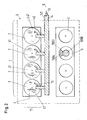
- FIG. 2 schematically an eight-cylinder V-engine with a robot-assisted masking system is shown.
- Fig. 2 shows an eight-cylinder V-engine 3 with a lower cylinder row according to the illustration, in which just the cylinder 5 is coated by means of a plasma spray gun 1000 by a plasma jet with coating material 1004.
- the upper row of cylinders 11 of the internal combustion engine 3 according to the illustration are simultaneously completely masked by a masking system 1 according to the invention and therefore protected from the dangerous overspray from the coating jet 1003 with which the cylinder 5 of the lower row is coated and at the same time cooled by the fluid 9 ,
- the particularly important for practice special embodiment of an inventive masking system 1 of Fig. 2 comprises four masking cylinders 4 each having a masking cover 41 which Masking cylinder 4 are placed in the cylinder bores 2 of the second cylinder 7.
- one or more of the masking cylinders is hollow and one or more of the other masking cylinders are solid.
- the four masking cylinders 4 are supported via the 4 masking covers 41 on a support arm 141 of a robot system 14, so that all second cylinder bores 7 can be masked or demasked at the same time by the robot system 14, by means of an in Fig. 2 not explicitly shown drive the support arm 141 is moved so that the masking cylinder can be sunk or pulled out into the second cylinder 7.
- a feed means 13 in the form of a feed line 13 is provided, through which the fluid 9 can be supplied to the flow gaps via the masking covers 41.
- all masking cylinders 4 can be simultaneously pulled out of the upper row of cylinders by means of the robot system 14 and subsequently placed in the lower row of cylinders to protect the cylinder walls of the lower row of cylinders.
- the engine block of the engine 3 may be e.g. be arranged on a strip line, so that automatically successively the cylinder bores of several engine blocks can be coated.
- the motor blocks are additionally mounted on a manipulator or on a movable robot, so that e.g. in order to place the masking system 1 according to the invention, the motor 3 can be pivoted, rotated or aligned in any other suitable way.
Landscapes
- Chemical & Material Sciences (AREA)
- Engineering & Computer Science (AREA)
- Physics & Mathematics (AREA)
- Plasma & Fusion (AREA)
- Chemical Kinetics & Catalysis (AREA)
- Materials Engineering (AREA)
- Mechanical Engineering (AREA)
- Metallurgy (AREA)
- Organic Chemistry (AREA)
- Cylinder Crankcases Of Internal Combustion Engines (AREA)
- Coating By Spraying Or Casting (AREA)
Description
- Die Erfindung betrifft ein Maskierungssystem zur Maskierung einer Zylinderbohrung einer Brennkraftmaschine während eines thermischen Beschichtungsvorgangs, sowie die Verwendung eines erfindungsgemässen Markierungssystems gemäss dem Oberbegriff des unabhängigen Anspruchs der jeweiligen Kategorie.
- Das thermische Beschichten von Zylinderlaufflächen von Verbrennungsmotoren durch verschiedene thermische Spritzverfahren ist heutzutage Stand der Technik und findet insbesondere bei Motoren für Kraftfahrzeuge aller Art, aber nicht nur hier, breite Anwendung. Dabei werden gewöhnlich die entsprechenden Zylinderlaufflächen durch verschiedene Verfahren vor dem thermischen Beschichten aktiviert, z.B. durch Korundstrahlen, Hartgussstrahlen, Hochdruckwasserstrahlen oder durch andere an sich bekannte Aktivierungsverfahren. Am häufigsten werden dabei Substrate aus leichtmetallischen Legierungen auf Al oder Mg Basis beschichtet.
- Ein weit verbreiteter Typ von Motoren sind Motoren in V-Bauweise, also Motoren, die zwei zueinander parallel verlaufende Zylinderreihen aufweisen, wobei die zwei Längsachsen von zwei benachbarten Zylinderbuchsen, die jeweils zu einer der beiden Zylinderreihen gehören, um einen bestimmten Winkel gegeneinander geneigt sind, wodurch die charakteristische V-Form des Motorblocks eines Motors in V-Bauweise entsteht.
- Bei solchen V-Motoren besteht beim thermischen Beschichten die Gefahr, dass, während der Beschichtung einer Zylinderwand einer Zylinderbohrung einer ersten Zylinderreihe, auf der Zylinderwand eines benachbarten Zylinders der zweiten Zylinderreihe Dämpfe, z.B. Metalldämpfe des Beschichtungsmaterials, die beim thermischen Beschichten nie ganz zu vermeiden sind, abgeschieden werden. Durch die Abscheidung der Metalldämpfe an den relativ kalten Wänden auf der Zylinderwand des Zylinders der zweiten Zylinderreihe, wird diese Zylinderwand in der zweiten Zylinderreihe durch die Metalldämpfe kontaminiert, was unter anderem eine negative Wirkung auf die Haftung einer später auf diesen Zylinder ebenfalls noch aufzubringenden Beschichtung hat. Zudem ist eine Kontamination durch ungeschmolzene Partikel und Overspray zu befürchten.
- Ein weiteres Problem ist die Erwärmung des Motorblocks durch den thermischen Beschichtungsvorgang. Da der Unterschied im Wärmeausdehnungskoeffizient zwischen thermischer Spritzschicht und Substrat relativ hoch sein kann, hat eine Temperatur des Substrats oberhalb von 120°C, worunter im wesentlichen eine Art mittlere Temperatur des Motorblocks zu verstehen ist, eine negative Wirkung auf das Eigenspannungsniveau der Schichten und oberhalb von 150°C besteht gar die Gefahr, dass das aus einer Leichtmetalllegierung gefertigte Bauteil, also der Motorblock, einen Verzug des Materials erleidet und damit unbrauchbar wird.
- Diese Problematik wird besonders deutlich, wenn man die thermischen Ausdehnungskoeffizienten typischer verwendeter Materialien betrachtet: typische Ausdehnungskoeffizienten thermischer Spritzschichten aus Eisenbasis-Legierungen liegen z.B. bei ca. 11×10-6/°C, während typische thermische Ausdehnungskoeffizienten von Aluminium basierten Substraten bei ca. 23×10-6/°C und bei Magnesium basierten Substraten typischerweise bei 27x10-6/°C liegen können. Das heisst, typische thermische Ausdehnungskoeffizienten der Substrate, also des Materials aus dem die Motorblöcke gefertigt sind, sind grössenordnungsmässig mehr als doppelt so gross wie die thermischen Ausdehnungskoeffizienten der aufgespritzten thermischen Spritzschichten.
- Im Stand der Technik sind verschiedene Vorrichtungen bekannt, die insbesondere das Problem der Kontamination von Zylinderlaufflächen mit den zuvor erwähnten Metalldämpfen zu lösen versuchen.
- So sind Vorrichtungen bekannt, bei welchen Zylinderbohrungen, die nicht beschichtet werden, mit einer Art aufblasbarem Ballon versiegelt werden, wie z.B. in der
US 2001/0029886 A beschrieben, was jedoch zu Wärmestaus führen kann und die oben erwähnten Probleme mit den thermischen Ausdehnungskoeffizienten noch verschärft. Es sind andere Systeme, z.B. gemässEP 1 136 583 A1 in Gebrauch, bei welchen durch das Kurbelwellengehäuse Abdeckungen zum Schutz der nicht zu beschichtenden Zylinderbohrungen eingeführt werden. Auch hier sind letztlich die thermischen Probleme nicht vollständig gelöst und, was mindestens ebenso wichtig ist, die Verwendung aller bekannten Systeme ist nur sehr schwer oder gar nicht zu automatisieren, insbesondere im Fall von Motoren der V-Bauweise, so dass der Beschichtungsprozess letztlich sehr teuer wird, weil viel Handarbeit bei der Beschichtung einer grossen Zahl von Motorblöcken notwendig ist. - Die
EP 1 685 910 A1 offenbart eine Vorrichtung zum Aufbringen einer Beschichtung auf einen Motorblock, mit welcher während der Beschichtung einer ersten Zylinderbank zum Schutz einer zweiten Zylinderbank eine Düse zum Absaugen von Gas aus der zweiten Zylinderbank vorgesehen ist. Allerdings ist auch hier vor allem die Kühlung des Zylinderblocks nicht ausreichend gewährleistet. - Die Aufgabe der Erfindung ist es daher, eine Vorrichtung zur Verfügung zu stellen, mit welcher die aus dem Stand der Technik bekannten Probleme, insbesondere die thermischen Probleme und die Probleme mit der Kontamination durch Metalldämpfe, beim thermischen Beschichten von Zylinderbohrungen von Brennkraftmaschinen vermieden werden, wobei gleichzeitig einfach und kostengünstig ein hoher Automatisierungsgrad erreichbar ist.
- Die diese Aufgaben lösenden Gegenstände der Erfindung sind durch die Merkmale des unabhängigen Anspruchs der jeweiligen Kategorie gekennzeichnet.
- Die jeweiligen abhängigen Ansprüche beziehen sich auf besonders vorteilhafte Ausführungsformen der Erfindung.
- Die Erfindung betrifft somit ein Maskierungssystem zur Maskierung einer Zylinderbohrung einer Brennkraftmaschine während eines thermischen Beschichtungsvorgangs, umfassend einen Maskierungskörper, der während des thermischen Beschichtungsvorgangs eines ersten Zylinders der Brennkraftmaschine zur Abdeckung einer Zylinderwand eines zweiten Zylinders in der Zylinderbohrung des zweiten Zylinders platzierbar ist. Dabei ist der Maskierungskörper derart ausgestaltet, dass zur Erzeugung einer Strömung eines Fluids zwischen dem Maskierungskörper und der Zylinderwand des zweiten Zylinders ein Strömungsspalt von vorgebbarer Breite einstellbar ist.
- Wesentlich für die Erfindung ist, dass das erfindungsgemässe Maskierungssystem einen Maskierungskörper umfasst, der einerseits eine nicht zu beschichtende Zylinderwand einer Zylinderbohrung während des Beschichtens einer anderen Zylinderwand im wesentlichen vollständig abdeckt und diese damit vor dem direkten Aufbringen von Metalldämpfen, die aus einem Beschichtungsstrahl stammen, mit dem der andere Zylinder beschichtet wird, schützt. Also verhindert, dass die nicht zu beschichtende Zylinderwand mittelbar oder unmittelbar dem Beschichtungsstrahl ausgesetzt wird.
- Anderseits ist der Maskierungskörper derart ausgestaltet, dass zwischen dem Maskierungskörper und der aktuell nicht zu beschichtenden Zylinderwand ein Strömungsspalt frei bleibt, so dass darin eine Luftströmung erzeugbar ist, die einerseits eine Kühlung des Motorblocks in der abgedeckten Zylinderbohrung bewirkt und anderseits verhindert, dass indirekt Metallstäube, die sich im Inneren des Motorblocks verteilen, sich auf der aktuell nicht zu beschichtenden Zylinderwand niederschlagen.
- Betrachtet man ein spezielles Ausführungsbeispiel der Erfindung, so wird z.B. auf einem gegenüberliegenden Zylinder während der Beschichtung ein geschlossenes Rohr mit einem kontrollierten Strömungsspalt zwischen Rohr und Zylinderlauffläche eingeführt. Durch entsprechende Öffnungen und einer angemessenen Absaugung wird eine Strömung von Luft bzw. anderer Fluide erreicht, die die Zylinderlauffläche kühlt und gleichzeitig die Abscheidung von Metalldämpfen auf dieser Zylinderlauffläche verhindert, da die Strömungen bzw. Turbulenzen der Metalldämpfe wirksam zurückgedrängt werden können.
- Bei der Beschichtung von Zylinderkurbelgehäusen in V-Bauweise wird jeweils bevorzugt eine Zylinderreihe beschichtet. Die ihr gegenüberliegende Zylinderreihe wird dabei durch ein erfindungsgemässes Maskierungssystem derart geschützt, dass z.B. ein Plasmastrahl einer rotierenden Plasmaspritzvorrichtung, die in axialer Richtung beim Beschichten durch die Zylinderbohrung geführt wird, welcher Plasmastrahl in einem unteren Umkehrpunkt im Bereich des Kurbelwellengehäuses des Motorblocks bis in die gegenüberliegende Bohrung reichen kann, die Zylinderwände der nicht zu beschichtenden Zylinderreihe nicht erreicht. Das heisst es kommt nicht zu dem gefürchteten "Overspraying", also der Kontamination einer nicht zu beschichtenden Zylinderwand durch Übersprühen aus einer Zylinderbohrung, die aktuell beschichtet wird. Dadurch wird verhindert, dass es zu Schichtablösungen kommt, wie sie aus dem Stand der Technik bekannt sind, was auftritt, wenn eine zuvor mit Metalldämpfen kontaminierte Zylinderwand später beschichtet wird.
- Ausserdem wird, wie bereits erwähnt, eine während des Beschichtungsvorgangs zwangsläufig stattfindende Erwärmung des Zylinderblocks durch den Wärmeübergang von geschmolzenem Pulver zum Substrat deutlich reduziert. Eine Überhitzung ist insbesondere bei dünnwandigen Bauteilen unbedingt zu vermeiden, weil dies zur Überhitzung des Zylinderblocks führen kann, was ebenfalls schädliche Schichtablösungen zur Folge haben kann. Auch diese schädlichen Wirkungen werden durch den Einsatz eines erfindungsgemässen Maskierungssystems vermieden, weil durch die Regulierung der Strömung des Fluids durch den Strömungsspalt das Maskierungssystem der vorliegenden Erfindung ein intelligentes Temperaturmanagement während des Beschichtungsprozesses gewährleistet.
- In einem speziellen Ausführungsbeispiel ist der Maskierungskörper ein hohler Maskierungskörper oder ein massiver Maskierungskörper, bevorzugt ein hohler Maskierungszylinder oder ein massiver Maskierungszylinder.
- Dabei ist der Maskierungskörper bevorzugt so ausgestaltet, dass der Strömungsspalt eine Breite von 0.1 mm bis 10 mm, bevorzugt eine Breite zwischen 0.2 mm und 5 mm, im speziellen eine Breite zwischen 0.4 mm und 3 mm hat. Dadurch ist gleichzeitig gewährleistet, dass der Strömungsspalt schmal genug ist, so dass eine direkte Kontamination der Zylinderwand des durch den Maskierungskörper geschützten Zylinders verhinderbar ist und gleichzeitig eine ausreichend starke Strömung im Strömungsspalt aufrecht erhalten werden kann, so dass eine ausreichende Kühlung erreichbar ist.
- In einem speziellen Ausführungsbeispiel umfasst ein erfindungsgemässes Maskierungssystem mindestens zwei Maskierungskörper, so dass mindestens zwei Zylinder, bevorzugt zwei benachbarte Zylinder gleichzeitig maskierbar sind, wobei in einem für die Praxis besonders wichtigen Ausführungsbeispiel das Maskierungssystem eine vorgebbare Anzahl von Maskierungskörpern umfasst und derart ausgestaltet ist, dass eine komplette Zylinderreihe einer Brennkraftmaschine in V-Bauweise gleichzeitig maskierbar ist.
- Bevorzugt umfasst der Maskierungskörper eine Maskierungsabdeckung und die Maskierungsabdeckung umfasst insbesondere einen mit dem Strömungsspalt verbindbaren Kanal, insbesondere einen Auslasskanal und / oder einen Einlasskanal zur Förderung des Fluids. Der Kanal kann dabei Öffnungen haben, von denen eine oder mehrere in der Maskierungsabdeckung vorgesehen sein können, über die das Fluid, z.B. Luft oder ein anderes Gas, beispielsweise durch eine Absaugvorrichtung, die am Kurbelgehäuse vorgesehen sein kann, absaugbar ist, so dass dadurch die Strömung im Strömungsspalt zwischen Maskierungskörper und Zylinderwand herstellbar ist.
- Es versteht sich, dass in einem anderen Ausführungsbeispiel auch Luft oder ein anderes Gas über die Öffnungen, von denen zum Beispiel mehrere in der Maskierungsabdeckung vorgesehen sein können und z.B. kreisförmig in der Nähe eines Rands der Maskierungsabdeckung angeordnet sein können, unter einem vorgebbaren Druck in den Strömungsspalt einbringbar ist oder über die Öffnungen absaugbar ist, wobei die Strömungsrichtung des Fluids, je nach dem ob das Fluid unter Druck in die Öffnungen eingeblasen oder aus diesen abgesaugt wird, entweder in das Kurbelgehäuse hinein oder aus diesem heraus gerichtet ist. Der Fachmann versteht, dass je nach Anforderung die Form der Öffnungen verschieden sein kann, z.B. kreisförmige Öffnungen, schlitzförmige Öffnungen oder Öffnungen von anderer geeigneter Form vorgesehen sein können.
- Als Fluid ist insbesondere ein Gas oder ein Gasgemisch, im speziellen Luft und / oder Stickstoff und / oder ein Edelgas, insbesondere Argon und / oder Helium zur Erzeugung der Strömung im Strömungsspalt besonders gut geeignet.
- Wie bereits erwähnt, kann am Kurbelwellenraum des zu beschichtenden Motorgehäuses ein Absaugmittel vorgesehen sein, so dass die Strömung des Fluids durch den Strömungsspalt durch den Kurbelwellenraum der Brennkraftmaschine absaugbar ist.
- Oder es kann auch, wie ebenfalls für ein spezielles Beispiel zuvor bereits erläutert, ein Einspeisemittel zur Einspeisung des Fluids in den Strömungsspalt vorgesehen sein, so dass die Strömung des Fluids durch den Strömungsspalt unter einem vorgebbaren Einspeisedruck erzeugbar ist.
- Eine Strömungsgeschwindigkeit des Fluids im Strömungsspalt ist bevorzugt grösser als 1 m/s, insbesondere grösser als 10 m/s, und liegt im Speziellen zwischen 1 m/s und 150 m/s, bevorzugt zwischen 10 m/s und 80 m/s. Dadurch wird einerseits eine ausreichende Kühlung des Motorblocks erreicht und andererseits eine genügend Starke Strömung im Strömungsspalt erzeugt, so dass sich kein Metalldampf auf einer nicht zu beschichtenden Zylinderlauffläche, die durch ein erfindungsgemässes Maskierungssystem geschützt ist, absetzten kann.
- Insbesondere um den Beschichtungsvorgang von Zylinderlaufflächen von Motorblöcken für die industrielle Massenproduktion vorteilhaft zu automatisieren, kann zur Positionierung des Maskierungskörpers ein Manipulator, insbesondere ein programmgesteuertes Robotersystem vorgesehen sein, so dass der Maskierungskörper automatisch nach einem vorgebbaren Programmanlaufschema in der Zylinderbohrung platzierbar ist.
- Vorteilhaft kann darüber hinaus eine Versorgungseinheit zur Bereitstellung des Fluids vorgesehen sein, die bevorzugt programmgesteuert steuer- und / oder regelbar ist, so dass z.B. die Durchflussmenge und / oder der Druck und / oder die Durchflussgeschwindigkeit des Fluidstromes im Strömungsspalt steuer- und / oder regelbar ist und z.B. in Abhängigkeit von der Zeit, der Art des zu beschichtenden Motorblocks oder in Abhängigkeit von bestimmten Beschichtungsparametern, wie Temperatur, Art der verwendeten Beschichtungsvorrichtung, Art des Beschichtungsmaterials, Art des Beschichtungsverfahrens usw. steuer- und / oder regelbar ist.
- Die Erfindung betrifft weiter die Verwendung eines erfindungsgemässen Maskierungssystems, wie in dieser Anmeldung ausführlich beschrieben, wobei der thermische Beschichtungsvorgang ein Plasmaspritzverfahren, bevorzugt ein Plasma APS Verfahren, ein Flammspritzverfahren, insbesondere ein Hochgeschwindigkeits Flammspritzverfahren und / oder ein anderes thermisches Spritzverfahren wie zum Beispiel ein Lichtbogen Drahtspritzverfahren umfasst.
- Dabei wird ein erfindungsgemässes Maskierungssystem insbesondere als Schutz gegen Kontamination einer Zylinderbohrung und / oder zur Kühlung während des thermischen Beschichtungsvorgangs verwendet.
- Es versteht sich, dass sich die Verwendung dabei sowohl auf die Verhinderung von Overspray eine bereits beschichtete Zylinderbohrung eines ersten Zylinders, aber selbstverständlich auch auf die Verhinderung von Overspray einer noch unbeschichteten Zylinderbohrung beziehen kann.
- Im Folgenden wird die Erfindung an Hand der Zeichnung näher erläutert. Es zeigen in schematischer Darstellung:
-
Fig. 1 einen Schnitt durch einen Zylinderblock eines Motors in V-Bauweise mit einem erfindungsgemässen Maskierungssystem; -
Fig. 2 einen acht Zylinder V-Motor mit einem Roboter unterstützten Maskierungssystem. -
Fig. 1 zeigt in einer Darstellung im Schnitt eine einfache Ausführungsvariante eines erfindungsgemässen Maskierungssystems während des Beschichtens einer Zylinderbohrung eines Motors in V-Bauweise, an welcher die Funktionsweise eines erfindungsgemässen Maskierungssystems, das im folgenden gesamthaft mit dem Bezugszeichen 1 bezeichnet ist, schematisch erläutert wird. - In
Fig. 1 ist ein Schnitt durch einen Motorblock eines Motors in V-Bauweise dargestellt, dessen zwei Zylinderreihen in an sich bekannter Weise parallel zueinander, unter einem Neigungswinkel α angeordnet sind. - Ein erster Zylinder 5, der darstellungsgemäss rechte Zylinder, wird gerade mit einer an sich bekannten rotierenden Plasmaspritzpistole 1000 beschichtet. Die Plasmaspritzpistole rotiert während des Beschichtungsvorgans im Zylinder 5 um eine Längsachse, wie der Pfeil 1002 andeutet und wird unter Rotation in axialer Richtung durch die Zylinderbohrung während des Beschichtungsvorgangs geführt. An einem unteren Ende der Plasmaspritzpistole 1000 tritt aus einer Spritzöffnung 1001 ein Plasmastrahl 1003 mit Beschichtungsmaterial 1004 aus, mit welchem Beschichtungsmaterial 1004 die Zylinderwand des Zylinders 5 beschichtet wird.
- Wie
Fig. 1 zeigt, befindet sich die Plasmaspritzpistole 1000 gerade in der Nähe ihres unteren Umkehrpunktes, dass heisst der Plasmastrahl 1003 mit Beschichtungsmaterial 1004 trifft nicht nur auf die zu beschichtende Zylinderwand des Zylinders 5, sondern reicht in das Kurbelgehäuse des V-Motors 3 und sogar bis in den nicht zu beschichtenden zweiten Zylinders 7 hinein. - Das heisst, ohne die Verwendung eines erfindungsgemässen Maskierungssystems 1 würde die Zylinderwand 6 des zweiten Zylinders 7 mit Beschichtungsmaterial 1004 kontaminiert und darüber hinaus durch den Plasmastrahl 1003 über Gebühr erwärmt.
- Um dies zu verhindern, ist in der Zylinderbohrung 2 des zweiten Zylinders 7 ein Maskierungskörper 4 gemäss der vorliegenden Erfindung vorgesehen, der im vorliegenden Beispiel der
Fig. 1 als Hohlzylinder 4 ausgestaltet ist und zusätzlich eine Maskierungsabdeckung 41 umfasst. Die Maskierungsabdeckung 41, die einen Deckel auf dem zweiten Zylinder 7 bzw. auf dem Markierungskörper 4 bildet, umfasst einen mit dem Strömungsspalt 10, der zwischen dem Maskierungszylinder 4 und der Zylinderwand 6 ausgebildet ist, verbundenen Kanal 42 mit Öffnungen 421, der im Beispiel derFig. 1 als Einlasskanal 42 zur Förderung des Fluids 9 in den Strömungsspalt 10 ausgebildet ist. - Die Strömung 8 des Fluids 9 im Strömungsspalt 10 wird dabei durch ein in
Fig. 1 nicht explizit dargestelltes Absaugmittel erzeugt, das in einer dem Fachmann an sich bekannten Weise im Kurbelgehäuse einen vorgebbaren Unterdruck erzeugt, so dass durch die Öffnungen 421 in der Maskierungsabdeckung 41 Luft angesaugt wird, die dann durch den mit der Öffnung 421 verbundenen Strömungsspalt 10 strömt, so dass der Zylinder 7 und damit der komplette Motorblock der Brennkraftmaschine 3 einerseits gekühlt wird und andererseits eine Abscheidung von Metalldämpfen auf der Zylinderwand 6 des zweiten Zylinders 7 verhindert wird. - In
Fig 2 ist schematisch ein acht Zylinder V-Motor mit einem Roboter unterstützten Maskierungssystem dargestellt. -
Fig. 2 zeigt einen acht Zylinder V-Motor 3 mit einer darstellungsgemäss unteren Zylinderreihe, in der gerade der Zylinder 5 mittels einer Plasmaspritzpistole 1000 durch einen Plasmastrahl mit Beschichtungsmaterial 1004 beschichtet wird. - Die darstellungsgemäss obere Zylinderreihe 11 der Brennkraftmaschine 3 ist dabei gleichzeitig komplett durch ein erfindungsgemässes Maskierungssystem 1 maskiert und damit vor dem gefährlichen Overspray aus dem Beschichtungsstrahl 1003, mit dem gerade der Zylinder 5 der unteren Reihe beschichtet wird, geschützt und wird gleichzeitig durch das Fluid 9 gekühlt.
- Das für die Praxis besonders wichtige spezielle Ausführungsbeispiel eines erfindungsgemässen Maskierungssystems 1 der
Fig. 2 umfasst vier Maskierungszylinder 4 mit jeweils einer Maskierungsabdeckung 41, welche Maskierungszylinder 4 in den Zylinderbohrungen 2 der zweiten Zylinder 7 platziert sind. - Wenn mehr als ein Maskierungszylinder 4 in ein und demselben Maskierungssystem gleichzeitig vorgesehen ist, ist es selbst verständlich, dass zum Beispiel einer oder mehrere der Maskierungszylinder hohl ist, und einer oder mehrer der anderen Maskierungszylinder massiv sind.
- Die vier Maskierungszylinder 4 sind über die 4 Maskierungsabdeckungen 41 an einem Trägerarm 141 eines Robotersystems 14 gehaltert, so dass durch das Robotersystem 14 alle zweiten Zylinderbohrungen 7 gleichzeitig maskiert bzw. demaskiert werden können, indem durch einen in
Fig. 2 nicht explizit dargestellten Antrieb der Trägerarm 141 so bewegt wird, dass die Maskierungszylinder in die zweiten Zylinder 7 versenkt bzw. herausgezogen werden können. - Im bzw. am Trägerarm 141 ist ein Einspeisemittel 13 in Form einer Zuleitung 13 vorgesehen, durch die das Fluid 9 über die Maskierungsabdeckungen 41 den Strömungsspalten zuführbar ist.
- Wenn nach dem Beschichten der darstellunggemäss unteren Zylinderreihe anschliessend die obere Zylinderreihe beschichtet werden soll, können alle Maskierungszylinder 4 gleichzeitig mittels des Robotersystems 14 aus der oberen Zylinderreihe herausgezogen werden und anschliessend in der unteren Zylinderreihe zum Schutz der Zylinderwände der unteren Zylinderreihe platziert werden. Dabei kann der Motorblock des Motors 3 z.B. auf einer Bandstrasse angeordnet sein, so dass automatisch nacheinander die Zylinderbohrungen von mehreren Motorblöcken beschichtet werden können. Es dabei möglich, dass auch die Motorblöcke zusätzlich auf einem Manipulator bzw. an einem bewegbaren Roboter montiert sind, so dass z.B. zum Platzieren des erfindunsggemässen Maskierungssystems 1 der Motor 3 geschwenkt, gedreht oder in anderer geeigneter Weise ausgerichtet werden kann.
Claims (14)
- Maskierungssystem zur Maskierung einer Zylinderbohrung (2) einer Brennkraftmaschine (3) während eines thermischen Beschichtungsvorgangs, umfassend einen Maskierungskörper (4), der während des thermischen Beschichtungsvorgangs eines ersten Zylinders (5) der Brennkraftmaschine (3) zur Abdeckung einer Zylinderwand (6) eines zweiten Zylinders (7) in der Zylinderbohrung (2) des zweiten Zylinders (7) platzierbar ist, dadurch gekennzeichnet, dass der Maskierungskörper (4) derart ausgestaltet ist, dass zur Erzeugung einer Strömung (8) eines Fluids (9) zwischen dem Maskierungskörper (4) und der Zylinderwand (6) des zweiten Zylinders (7) ein Strömungsspalt (10) von vorgebbarer Breite einstellbar ist.
- Maskierungssystem nach Anspruch 1, wobei der Strömungsspalt (10) eine Breite von 0.1 mm bis 10 mm hat.
- Maskierungssystem nach einem der vorangehenden Ansprüche, wobei das Maskierungssystem mindestens zwei Maskierungskörper (4) umfasst, so dass mindestens zwei Zylinder (7) gleichzeitig maskierbar sind.
- Maskierungssystem nach einem der vorangehenden Ansprüche, wobei das Maskierungssystem eine vorgebbare Anzahl von Maskierungskörpern (4) umfasst und derart ausgestaltet ist, dass eine komplette Zylinderreihe (11) einer Brennkraftmaschine (3) in V-Bauweise gleichzeitig maskierbar ist.
- Maskierungssystem nach einem der vorangehenden Ansprüche, wobei der Maskierungskörper (4) eine Maskierungsabdeckung (41) umfasst.
- Maskierungssystem nach Anspruch 5, wobei die Maskierungsabdeckung (41) einen mit dem Strömungsspalt (10) verbundenen Kanal (42) zur Förderung des Fluids (9) umfasst.
- Maskierungssystem nach einem der vorangehenden Ansprüche, wobei das Fluid (9) ein Gas oder ein Gasgemisch ist.
- Maskierungssystem nach einem der vorangehenden Ansprüche, wobei ein Absaugmittel vorgesehen ist, so dass die Strömung des Fluids (9) durch den Strömungsspalt (10) durch einen Kurbelwellenraum (12) der Brennkraftmaschine (3) absaugbar ist.
- Maskierungssystem nach einem der vorangehenden Ansprüche, wobei ein Einspeisemittel (13) zur Einspeisung des Fluids (9) in den Strömungsspalt (10) vorgesehen ist, so dass die Strömung (8) des Fluids (9) durch den Strömungsspalt (10) unter einem vorgebbaren Einspeisedruck erzeugbar ist.
- Maskierungssystem nach einem der vorangehenden Ansprüche, wobei eine Strömungsgeschwindigkeit des Fluids (9) im Strömungsspalt (10) grösser als 1 m/s ist.
- Maskierungssystem nach einem der vorangehenden Ansprüche, wobei ein Manipulator (14) vorgesehen ist, so dass der Maskierungskörper automatisch nach einem vorgebbaren Programmanlaufschema in der Zylinderbohrung (2) platzierbar ist.
- Maskierungssystem nach einem der vorangehenden Ansprüche, wobei eine programmgesteuerte Versorgungseinheit zur Bereitstellung des Fluids (9) vorgesehen ist.
- Verwendung eines Maskierungssystems (1) nach einem der Ansprüche 1 bis 12, wobei der thermische Beschichtungsvorgang ein Plasmaspritzverfahren, ein Plasma APS Verfahren, ein Flammspritzverfahren, ein Hochgeschwindigkeits Flammspritzverfahren oder ein anderes thermisches Spritzverfahren, wie zum Beispiel ein Lichtbogen Drahtspritzverfahren umfasst.
- Verwendung nach Anspruch 13, wobei das Maskierungssystem (1) als Schutz gegen Kontamination einer Zylinderbohrung (2) oder zur Kühlung während des thermischen Beschichtungsvorgangs verwendet wird.
Priority Applications (1)
| Application Number | Priority Date | Filing Date | Title |
|---|---|---|---|
| EP07109434A EP1884293B1 (de) | 2006-07-24 | 2007-06-01 | Maskierungssystem zur Maskierung einer Zylinderbohrung |
Applications Claiming Priority (2)
| Application Number | Priority Date | Filing Date | Title |
|---|---|---|---|
| EP06117756 | 2006-07-24 | ||
| EP07109434A EP1884293B1 (de) | 2006-07-24 | 2007-06-01 | Maskierungssystem zur Maskierung einer Zylinderbohrung |
Publications (2)
| Publication Number | Publication Date |
|---|---|
| EP1884293A1 EP1884293A1 (de) | 2008-02-06 |
| EP1884293B1 true EP1884293B1 (de) | 2009-08-12 |
Family
ID=38884590
Family Applications (1)
| Application Number | Title | Priority Date | Filing Date |
|---|---|---|---|
| EP07109434A Not-in-force EP1884293B1 (de) | 2006-07-24 | 2007-06-01 | Maskierungssystem zur Maskierung einer Zylinderbohrung |
Country Status (1)
| Country | Link |
|---|---|
| EP (1) | EP1884293B1 (de) |
Families Citing this family (4)
| Publication number | Priority date | Publication date | Assignee | Title |
|---|---|---|---|---|
| DE102008028959A1 (de) | 2008-06-18 | 2009-01-02 | Daimler Ag | Maske zum thermischen Beschichten einer Zylinderbohrung und Verfahren zum thermischen Beschichten der Zylinderbohrung |
| DE102012112488B4 (de) * | 2012-12-18 | 2017-07-13 | Gebr. Heller Maschinenfabrik Gmbh | Lichtbogen-Drahtspritz-Beschichtungsverfahren für Zylinderbohrungen von Verbrennungsmotoren |
| DE102016116815A1 (de) | 2016-09-08 | 2018-03-08 | Dr. Ing. H.C. F. Porsche Aktiengesellschaft | Verfahren zur Beschichtung eines Zylinders einer Verbrennungskraftmaschine und Zylinder für eine Verbrennungskraftmaschine |
| DE102018206707A1 (de) * | 2018-05-02 | 2019-11-07 | MTU Aero Engines AG | Verfahren zum beschichten eines bauteils einer strömungsmaschine |
Family Cites Families (5)
| Publication number | Priority date | Publication date | Assignee | Title |
|---|---|---|---|---|
| US5573814A (en) * | 1995-10-30 | 1996-11-12 | Ford Motor Company | Masking cylinder bore extremities from internal thermal spraying |
| US6395090B1 (en) * | 1999-08-16 | 2002-05-28 | Ford Global Technologies, Inc. | Masking for engine blocks for thermally sprayed coatings |
| TR200401050T4 (tr) * | 2000-03-20 | 2004-07-21 | Sulzer Metco Ag | İçten yanmalı motorlarda silindir duvarlarının termik kaplaması için yöntem ve tertibat. |
| DE50102898D1 (de) * | 2000-05-03 | 2004-08-26 | Sulzer Metco Ag Wohlen | Anordnung zum Schutz von Zylinderwandungen von Motorblöcken |
| JP4497086B2 (ja) * | 2005-01-28 | 2010-07-07 | 日産自動車株式会社 | シリンダブロックの溶射マスキング方法および同マスキング装置ならびに気体噴出ノズル |
-
2007
- 2007-06-01 EP EP07109434A patent/EP1884293B1/de not_active Not-in-force
Also Published As
| Publication number | Publication date |
|---|---|
| EP1884293A1 (de) | 2008-02-06 |
Similar Documents
| Publication | Publication Date | Title |
|---|---|---|
| EP2075074B1 (de) | Maskierungssystem zur Maskierung eines Kurbelraums einer Brennkraftmaschine | |
| DE10262198B4 (de) | Verfahren zur Herstellung eines Produkts | |
| DE69020507T2 (de) | Ablösung von plasmagespritzten oder gesinterten Beschichtungen mittels eines Wasserstrahls. | |
| DE10230847B3 (de) | Verfahren und Vorrichtung zur Innenbeschichtung von Hohlräumen durch thermisches Spritzen | |
| EP2741862B1 (de) | Vorrichtung zum erzeugen eines pulsierenden mit druck beaufschlagten fluidstrahls | |
| DE69504944T2 (de) | Verfahren zur Herstellung von Motorblöcken mit beschichteten Zylinderbohrungen | |
| DE69619769T2 (de) | Maskierung von Zylinderbohrungenenden beim internen thermischen Spritzen | |
| DE69311626T2 (de) | Vorrichtung und Methode zur Druckstrahlreinigung von metallischen Oberflächen | |
| DD259586A5 (de) | Verfahren zur herstellung von gespruehten abreibbaren beschichtungen und nach dem verfahren hergestellte beschichtung | |
| US8500907B2 (en) | Masking system for the masking of a cylinder bore | |
| EP2455510A2 (de) | Vorrichtung für das thermische Beschichten von Zylinderinnenflächen bei Kurbelgehäusen | |
| EP1685910B1 (de) | Abdeckung eines Motorblocks während des Beschichtens | |
| WO2012175407A1 (de) | Vorrichtung zum behandeln von werkstücken | |
| DE102015115289A1 (de) | Turbinenkomponenten mit gestuften Öffnungen | |
| EP1884293A1 (de) | Maskierungssystem zur Maskierung einer Zylinderbohrung | |
| DE102015121648B4 (de) | Turbinenkomponenten-Oberflächenbehandlungsverfahren | |
| DE68927035T2 (de) | Verfahren und Vorrichtung zur Reinigung eines elektrostatischen Sprühkopfes | |
| DE102017213359B4 (de) | Prozessbox zum thermischen Beschichten einer metallischen Innenraum-Oberfläche,Beschichtungsanlage zum thermischen Beschichten eines Zylinderkurbelgehäuses für eine Verbrennungskraftmaschine und Verfahren zum thermischen Beschichten einer metallischen Innenraum-Oberfläche eines Objekts | |
| EP1136583B1 (de) | Verfahren sowie Vorrichtung zum thermischen Beschichten von Zylinderwandungen von Verbrennungsmotoren | |
| EP2533911B1 (de) | Verfahren zum abtragen von overspray thermischer spritzschichten | |
| DE102004038177B4 (de) | Verfahren zum thermischen Beschichten einer gegossenen Zylinderbohrung | |
| DE19810382C1 (de) | Flammspritzverfahren zur Vorbehandlung und Beschichtung von Oberflächen und Anwendung des Verfahrens | |
| DE102004038173B4 (de) | Verfahren zum thermischen Spritzen von Zylinderlaufflächen bei mehrreihigen Motoren | |
| WO2013083672A1 (de) | Plasmaspritzgerät, sowie beschichtungsverfahren | |
| DE69411219T2 (de) | Befestigung und Verfahren zum Kühlen Rohrsubstrats bein thermischen Spritzen |
Legal Events
| Date | Code | Title | Description |
|---|---|---|---|
| PUAI | Public reference made under article 153(3) epc to a published international application that has entered the european phase |
Free format text: ORIGINAL CODE: 0009012 |
|
| AK | Designated contracting states |
Kind code of ref document: A1 Designated state(s): AT BE BG CH CY CZ DE DK EE ES FI FR GB GR HU IE IS IT LI LT LU LV MC MT NL PL PT RO SE SI SK TR |
|
| AX | Request for extension of the european patent |
Extension state: AL BA HR MK YU |
|
| 17P | Request for examination filed |
Effective date: 20080331 |
|
| 17Q | First examination report despatched |
Effective date: 20080505 |
|
| AKX | Designation fees paid |
Designated state(s): AT BE BG CH CY CZ DE DK EE ES FI FR GB GR HU IE IS IT LI LT LU LV MC MT NL PL PT RO SE SI SK TR |
|
| RTI1 | Title (correction) |
Free format text: MASKING SYSTEM FOR MASKING A CYLINDER HOLE |
|
| GRAP | Despatch of communication of intention to grant a patent |
Free format text: ORIGINAL CODE: EPIDOSNIGR1 |
|
| GRAC | Information related to communication of intention to grant a patent modified |
Free format text: ORIGINAL CODE: EPIDOSCIGR1 |
|
| GRAS | Grant fee paid |
Free format text: ORIGINAL CODE: EPIDOSNIGR3 |
|
| GRAA | (expected) grant |
Free format text: ORIGINAL CODE: 0009210 |
|
| AK | Designated contracting states |
Kind code of ref document: B1 Designated state(s): AT BE BG CH CY CZ DE DK EE ES FI FR GB GR HU IE IS IT LI LT LU LV MC MT NL PL PT RO SE SI SK TR |
|
| REG | Reference to a national code |
Ref country code: GB Ref legal event code: FG4D Free format text: NOT ENGLISH |
|
| REG | Reference to a national code |
Ref country code: CH Ref legal event code: NV Representative=s name: SULZER MANAGEMENT AG PATENTABTEILUNG/0067 Ref country code: CH Ref legal event code: EP |
|
| REG | Reference to a national code |
Ref country code: IE Ref legal event code: FG4D |
|
| REF | Corresponds to: |
Ref document number: 502007001277 Country of ref document: DE Date of ref document: 20090924 Kind code of ref document: P |
|
| LTIE | Lt: invalidation of european patent or patent extension |
Effective date: 20090812 |
|
| PG25 | Lapsed in a contracting state [announced via postgrant information from national office to epo] |
Ref country code: IS Free format text: LAPSE BECAUSE OF FAILURE TO SUBMIT A TRANSLATION OF THE DESCRIPTION OR TO PAY THE FEE WITHIN THE PRESCRIBED TIME-LIMIT Effective date: 20091212 Ref country code: LT Free format text: LAPSE BECAUSE OF FAILURE TO SUBMIT A TRANSLATION OF THE DESCRIPTION OR TO PAY THE FEE WITHIN THE PRESCRIBED TIME-LIMIT Effective date: 20090812 Ref country code: FI Free format text: LAPSE BECAUSE OF FAILURE TO SUBMIT A TRANSLATION OF THE DESCRIPTION OR TO PAY THE FEE WITHIN THE PRESCRIBED TIME-LIMIT Effective date: 20090812 Ref country code: SE Free format text: LAPSE BECAUSE OF FAILURE TO SUBMIT A TRANSLATION OF THE DESCRIPTION OR TO PAY THE FEE WITHIN THE PRESCRIBED TIME-LIMIT Effective date: 20090812 Ref country code: ES Free format text: LAPSE BECAUSE OF FAILURE TO SUBMIT A TRANSLATION OF THE DESCRIPTION OR TO PAY THE FEE WITHIN THE PRESCRIBED TIME-LIMIT Effective date: 20091123 |
|
| NLV1 | Nl: lapsed or annulled due to failure to fulfill the requirements of art. 29p and 29m of the patents act | ||
| PG25 | Lapsed in a contracting state [announced via postgrant information from national office to epo] |
Ref country code: PL Free format text: LAPSE BECAUSE OF FAILURE TO SUBMIT A TRANSLATION OF THE DESCRIPTION OR TO PAY THE FEE WITHIN THE PRESCRIBED TIME-LIMIT Effective date: 20090812 Ref country code: NL Free format text: LAPSE BECAUSE OF FAILURE TO SUBMIT A TRANSLATION OF THE DESCRIPTION OR TO PAY THE FEE WITHIN THE PRESCRIBED TIME-LIMIT Effective date: 20090812 Ref country code: SI Free format text: LAPSE BECAUSE OF FAILURE TO SUBMIT A TRANSLATION OF THE DESCRIPTION OR TO PAY THE FEE WITHIN THE PRESCRIBED TIME-LIMIT Effective date: 20090812 Ref country code: LV Free format text: LAPSE BECAUSE OF FAILURE TO SUBMIT A TRANSLATION OF THE DESCRIPTION OR TO PAY THE FEE WITHIN THE PRESCRIBED TIME-LIMIT Effective date: 20090812 |
|
| REG | Reference to a national code |
Ref country code: IE Ref legal event code: FD4D |
|
| PG25 | Lapsed in a contracting state [announced via postgrant information from national office to epo] |
Ref country code: BG Free format text: LAPSE BECAUSE OF FAILURE TO SUBMIT A TRANSLATION OF THE DESCRIPTION OR TO PAY THE FEE WITHIN THE PRESCRIBED TIME-LIMIT Effective date: 20091112 Ref country code: PT Free format text: LAPSE BECAUSE OF FAILURE TO SUBMIT A TRANSLATION OF THE DESCRIPTION OR TO PAY THE FEE WITHIN THE PRESCRIBED TIME-LIMIT Effective date: 20091212 |
|
| PG25 | Lapsed in a contracting state [announced via postgrant information from national office to epo] |
Ref country code: RO Free format text: LAPSE BECAUSE OF FAILURE TO SUBMIT A TRANSLATION OF THE DESCRIPTION OR TO PAY THE FEE WITHIN THE PRESCRIBED TIME-LIMIT Effective date: 20090812 Ref country code: DK Free format text: LAPSE BECAUSE OF FAILURE TO SUBMIT A TRANSLATION OF THE DESCRIPTION OR TO PAY THE FEE WITHIN THE PRESCRIBED TIME-LIMIT Effective date: 20090812 Ref country code: CZ Free format text: LAPSE BECAUSE OF FAILURE TO SUBMIT A TRANSLATION OF THE DESCRIPTION OR TO PAY THE FEE WITHIN THE PRESCRIBED TIME-LIMIT Effective date: 20090812 Ref country code: EE Free format text: LAPSE BECAUSE OF FAILURE TO SUBMIT A TRANSLATION OF THE DESCRIPTION OR TO PAY THE FEE WITHIN THE PRESCRIBED TIME-LIMIT Effective date: 20090812 Ref country code: IE Free format text: LAPSE BECAUSE OF FAILURE TO SUBMIT A TRANSLATION OF THE DESCRIPTION OR TO PAY THE FEE WITHIN THE PRESCRIBED TIME-LIMIT Effective date: 20090812 |
|
| PG25 | Lapsed in a contracting state [announced via postgrant information from national office to epo] |
Ref country code: SK Free format text: LAPSE BECAUSE OF FAILURE TO SUBMIT A TRANSLATION OF THE DESCRIPTION OR TO PAY THE FEE WITHIN THE PRESCRIBED TIME-LIMIT Effective date: 20090812 |
|
| PLBE | No opposition filed within time limit |
Free format text: ORIGINAL CODE: 0009261 |
|
| STAA | Information on the status of an ep patent application or granted ep patent |
Free format text: STATUS: NO OPPOSITION FILED WITHIN TIME LIMIT |
|
| 26N | No opposition filed |
Effective date: 20100517 |
|
| PG25 | Lapsed in a contracting state [announced via postgrant information from national office to epo] |
Ref country code: GR Free format text: LAPSE BECAUSE OF FAILURE TO SUBMIT A TRANSLATION OF THE DESCRIPTION OR TO PAY THE FEE WITHIN THE PRESCRIBED TIME-LIMIT Effective date: 20091113 |
|
| BERE | Be: lapsed |
Owner name: SULZER METCO A.G. Effective date: 20100630 |
|
| PG25 | Lapsed in a contracting state [announced via postgrant information from national office to epo] |
Ref country code: MC Free format text: LAPSE BECAUSE OF NON-PAYMENT OF DUE FEES Effective date: 20100630 |
|
| PG25 | Lapsed in a contracting state [announced via postgrant information from national office to epo] |
Ref country code: IT Free format text: LAPSE BECAUSE OF FAILURE TO SUBMIT A TRANSLATION OF THE DESCRIPTION OR TO PAY THE FEE WITHIN THE PRESCRIBED TIME-LIMIT Effective date: 20090812 |
|
| PG25 | Lapsed in a contracting state [announced via postgrant information from national office to epo] |
Ref country code: MT Free format text: LAPSE BECAUSE OF FAILURE TO SUBMIT A TRANSLATION OF THE DESCRIPTION OR TO PAY THE FEE WITHIN THE PRESCRIBED TIME-LIMIT Effective date: 20090812 |
|
| PG25 | Lapsed in a contracting state [announced via postgrant information from national office to epo] |
Ref country code: BE Free format text: LAPSE BECAUSE OF NON-PAYMENT OF DUE FEES Effective date: 20100630 |
|
| PGFP | Annual fee paid to national office [announced via postgrant information from national office to epo] |
Ref country code: GB Payment date: 20110729 Year of fee payment: 5 |
|
| PG25 | Lapsed in a contracting state [announced via postgrant information from national office to epo] |
Ref country code: CY Free format text: LAPSE BECAUSE OF FAILURE TO SUBMIT A TRANSLATION OF THE DESCRIPTION OR TO PAY THE FEE WITHIN THE PRESCRIBED TIME-LIMIT Effective date: 20090812 |
|
| PG25 | Lapsed in a contracting state [announced via postgrant information from national office to epo] |
Ref country code: LU Free format text: LAPSE BECAUSE OF NON-PAYMENT OF DUE FEES Effective date: 20100601 Ref country code: HU Free format text: LAPSE BECAUSE OF FAILURE TO SUBMIT A TRANSLATION OF THE DESCRIPTION OR TO PAY THE FEE WITHIN THE PRESCRIBED TIME-LIMIT Effective date: 20100213 |
|
| PG25 | Lapsed in a contracting state [announced via postgrant information from national office to epo] |
Ref country code: TR Free format text: LAPSE BECAUSE OF FAILURE TO SUBMIT A TRANSLATION OF THE DESCRIPTION OR TO PAY THE FEE WITHIN THE PRESCRIBED TIME-LIMIT Effective date: 20090812 |
|
| GBPC | Gb: european patent ceased through non-payment of renewal fee |
Effective date: 20120601 |
|
| PG25 | Lapsed in a contracting state [announced via postgrant information from national office to epo] |
Ref country code: GB Free format text: LAPSE BECAUSE OF NON-PAYMENT OF DUE FEES Effective date: 20120601 |
|
| REG | Reference to a national code |
Ref country code: AT Ref legal event code: MM01 Ref document number: 439192 Country of ref document: AT Kind code of ref document: T Effective date: 20120601 |
|
| PG25 | Lapsed in a contracting state [announced via postgrant information from national office to epo] |
Ref country code: AT Free format text: LAPSE BECAUSE OF NON-PAYMENT OF DUE FEES Effective date: 20120601 |
|
| REG | Reference to a national code |
Ref country code: CH Ref legal event code: NV Representative=s name: INTELLECTUAL PROPERTY SERVICES GMBH, CH |
|
| PGFP | Annual fee paid to national office [announced via postgrant information from national office to epo] |
Ref country code: DE Payment date: 20140619 Year of fee payment: 8 Ref country code: CH Payment date: 20140618 Year of fee payment: 8 |
|
| PGFP | Annual fee paid to national office [announced via postgrant information from national office to epo] |
Ref country code: FR Payment date: 20140619 Year of fee payment: 8 |
|
| REG | Reference to a national code |
Ref country code: DE Ref legal event code: R119 Ref document number: 502007001277 Country of ref document: DE |
|
| REG | Reference to a national code |
Ref country code: CH Ref legal event code: PL |
|
| REG | Reference to a national code |
Ref country code: FR Ref legal event code: ST Effective date: 20160229 |
|
| PG25 | Lapsed in a contracting state [announced via postgrant information from national office to epo] |
Ref country code: DE Free format text: LAPSE BECAUSE OF NON-PAYMENT OF DUE FEES Effective date: 20160101 Ref country code: CH Free format text: LAPSE BECAUSE OF NON-PAYMENT OF DUE FEES Effective date: 20150630 Ref country code: LI Free format text: LAPSE BECAUSE OF NON-PAYMENT OF DUE FEES Effective date: 20150630 |
|
| PG25 | Lapsed in a contracting state [announced via postgrant information from national office to epo] |
Ref country code: FR Free format text: LAPSE BECAUSE OF NON-PAYMENT OF DUE FEES Effective date: 20150630 |