EP1884290A1 - Closable dispensing pump for fluid substances - Google Patents
Closable dispensing pump for fluid substances Download PDFInfo
- Publication number
- EP1884290A1 EP1884290A1 EP07112457A EP07112457A EP1884290A1 EP 1884290 A1 EP1884290 A1 EP 1884290A1 EP 07112457 A EP07112457 A EP 07112457A EP 07112457 A EP07112457 A EP 07112457A EP 1884290 A1 EP1884290 A1 EP 1884290A1
- Authority
- EP
- European Patent Office
- Prior art keywords
- stem
- pushbutton
- pump
- dispensing
- aperture
- Prior art date
- Legal status (The legal status is an assumption and is not a legal conclusion. Google has not performed a legal analysis and makes no representation as to the accuracy of the status listed.)
- Granted
Links
Images


Classifications
-
- B—PERFORMING OPERATIONS; TRANSPORTING
- B05—SPRAYING OR ATOMISING IN GENERAL; APPLYING FLUENT MATERIALS TO SURFACES, IN GENERAL
- B05B—SPRAYING APPARATUS; ATOMISING APPARATUS; NOZZLES
- B05B11/00—Single-unit hand-held apparatus in which flow of contents is produced by the muscular force of the operator at the moment of use
- B05B11/0005—Components or details
- B05B11/0027—Means for neutralising the actuation of the sprayer ; Means for preventing access to the sprayer actuation means
- B05B11/0029—Valves not actuated by pressure
-
- B—PERFORMING OPERATIONS; TRANSPORTING
- B05—SPRAYING OR ATOMISING IN GENERAL; APPLYING FLUENT MATERIALS TO SURFACES, IN GENERAL
- B05B—SPRAYING APPARATUS; ATOMISING APPARATUS; NOZZLES
- B05B11/00—Single-unit hand-held apparatus in which flow of contents is produced by the muscular force of the operator at the moment of use
- B05B11/01—Single-unit hand-held apparatus in which flow of contents is produced by the muscular force of the operator at the moment of use characterised by the means producing the flow
- B05B11/10—Pump arrangements for transferring the contents from the container to a pump chamber by a sucking effect and forcing the contents out through the dispensing nozzle
- B05B11/1001—Piston pumps
-
- B—PERFORMING OPERATIONS; TRANSPORTING
- B05—SPRAYING OR ATOMISING IN GENERAL; APPLYING FLUENT MATERIALS TO SURFACES, IN GENERAL
- B05B—SPRAYING APPARATUS; ATOMISING APPARATUS; NOZZLES
- B05B11/00—Single-unit hand-held apparatus in which flow of contents is produced by the muscular force of the operator at the moment of use
- B05B11/01—Single-unit hand-held apparatus in which flow of contents is produced by the muscular force of the operator at the moment of use characterised by the means producing the flow
- B05B11/10—Pump arrangements for transferring the contents from the container to a pump chamber by a sucking effect and forcing the contents out through the dispensing nozzle
- B05B11/1042—Components or details
- B05B11/1059—Means for locking a pump or its actuation means in a fixed position
-
- B—PERFORMING OPERATIONS; TRANSPORTING
- B05—SPRAYING OR ATOMISING IN GENERAL; APPLYING FLUENT MATERIALS TO SURFACES, IN GENERAL
- B05B—SPRAYING APPARATUS; ATOMISING APPARATUS; NOZZLES
- B05B11/00—Single-unit hand-held apparatus in which flow of contents is produced by the muscular force of the operator at the moment of use
- B05B11/01—Single-unit hand-held apparatus in which flow of contents is produced by the muscular force of the operator at the moment of use characterised by the means producing the flow
- B05B11/10—Pump arrangements for transferring the contents from the container to a pump chamber by a sucking effect and forcing the contents out through the dispensing nozzle
- B05B11/1042—Components or details
- B05B11/1073—Springs
- B05B11/1074—Springs located outside pump chambers
Definitions
- the present invention relates to a closable dispensing pump for fluid substances withdrawable from a container in accordance with the introduction to the main claim.
- the invention relates in particular to a dispensing pump for creams or the like.
- Closable dispensing pumps are known.
- One such pump is described in US 3,216,625 .
- the pump in question has a stem integral with a dispensing pushbutton.
- the stem is movable within a pump endpiece, the endpiece being fixed to the pump body.
- a thread is provided on the stem, with a corresponding counter-thread provided in the endpiece.
- US 4,368,830 shows a pump with a stem on which an operating and dispensing pushbutton is mounted.
- the stem is slidable through an endpiece, the pushbutton presenting an elastic tooth which when the pushbutton is pressed into its end of stroke position snaps against an abutment provided in the endpiece, to act as a stop for maintaining the pushbutton in that position. Pushbutton movement is therefore prevented and the pump is closed.
- the known art presents the drawback that, when the pump is in its closed position, the entire length of the dispensing conduit (i.e. from the dispensing aperture to the dispensing valve) remains in contact with the outside. Consequently the product inside this conduit, which is in contact with the outside atmosphere, can dry and obstruct the conduit.
- this conduit obstruction can cause pump blockage.
- the product to be dispensed is alcohol based, it can evaporate completely, with considerable product wastage.
- An object of the present invention is therefore to provide a closable dispensing pump for substances withdrawable from a container, by which the technical problems of the known art are solved and in particular in which when the pump is closed the entire product inside the dispensing conduit is prevented from contact with the outside.
- a further object of the present invention is to provide a closable pump which minimizes the risk of malfunction due to obstruction of the dispensing conduit.
- Another object of the present invention is to provide a pump by which dispensing product wastage is prevented.
- a further object of the invention is to prevent the entire product inside the dispensing conduit from being able to be contaminated by atmospheric air.
- Known pumps comprise a cup-shaped body 5 defining an intake, containing and compression chamber 6 in which a known piston 7 is sealedly slidable, driven by a stem 2.
- the cup-shaped body presents at least one intake hole 8 closed by at least one first valve 9 of known type and communicating via a dip tube 10 with the interior of the container on which the pump 1 is mounted.
- the stem is internally hollow, its cavity communicating via at least one second valve 12, also of known type, with the compression chamber 6.
- the stem 2 is slidably mounted through an endpiece 13 which closes said cup-shaped body 5. More precisely, the stem 2 is guided through the endpiece 13 by a cylindrical guide surface 13a thereof. This surface presents a projection 13b which engages in a groove 2a present in the stem outer surface to make the stem 2 and endpiece 13 torsionally rigid. In this respect, the stem 2 can slide through the endpiece 13 to drive the piston 7, but cannot rotate about the endpiece, this rotation being prevented by said projection 13a.
- a dispensing pushbutton 4 Mounted on the stem 2 there is a dispensing pushbutton 4 presenting a second passage 14 for dispensing the fluid substance and opening towards the outside of said dispensing pushbutton.
- the stem 2 presents a flat first surface 2b of circular contact section which cooperates by contact with a second contacting surface 4a of said dispensing pushbutton 4, which is also flat and of circular section (and consequently of complementary shape to the first).
- the first contacting surface 2b and the second contacting surface 4a cooperate frontally and rest against each other when the stem is inserted into the pushbutton.
- the stem cylindrical surface also presents an undercut 2c which locks the stem in a cylindrical hole 4b provided in the pushbutton; slight interference is present between the stem and said cylindrical hole 4b.
- a first passage 3 is provided presenting a first aperture 3a and connecting said first aperture 3a to the cavity in the stem 2.
- the passage 3 is substantially an axial hole provided in a position offset from the stem axis A, the aperture 3a also consequently being offset from this latter.
- the second passage 14 presents a substantially linear first portion 14a connected to a second portion 14 when the pushbutton is mounted on the stem, has its axis substantially parallel to the stem axis A.
- This second portion 14b presents an aperture 14c at the pushbutton second surface 4a.
- the second aperture 14c is offset from the axis A, and when the pushbutton is in a first open position the second aperture 14c faces and is substantially coaxial with the first aperture 3a of the stem 2, so that these apertures communicate and the fluid product can be dispensed by operating the pushbutton.
- first aperture 3a and second aperture 14c have identical dimensions and shape.
- the first aperture 3a and the second aperture 14c do not face each other but each of them contact and faces the second contacting surface 4a and the first contacting surface 2a respectively.
- the first aperture 3a is hence closed substantially tightly and the fluid product in the stem cavity and in the first passage 3 is isolated from the outside atmosphere.
- the dispensing pushbutton 4 presents a cylindrical ring 20 which is integral with the pushbutton 4 and from which a pair of first abutments 21 a, 21 b extend radially in mutual alignment.
- the endpiece presents a pair of cylindrical second abutments 22a, 22b, these being separated from each other by a pair of slots 23a, 23b.
- each of the first abutments 21 a, 21 b is aligned with one of the slots 23a, 23b.
- each of the slots 23a, 23b receives the relative first abutment 21 a, 21 b, hence enabling the pushbutton to move and dispense the product.
- each of the first abutments 21 a, 21 b faces one of the second abutments 22a, 22b of the endpiece, so preventing pushbutton movement.
- conventional stops are provided on the second abutments 22a, 22b to cooperate with said first abutments 21 a, 21 b, to limit pushbutton rotation to between its open position and its closed position.
- Figures 5-9 show a preferred embodiment of the present pump. These figures show only a part of the stem and pushbutton, the pump connected to the stem being of any type.
- the stem 70 is sealedly inserted in a cavity 71 suitably provided in the dispensing pushbutton 72, and is locked in its seat by a snap-acting undercut 73.
- the undercut enables the pushbutton to rotate about the stem axis.
- the seal is provided by the contact between the stem outer surface 70b and that surface 71 A defining the cavity.
- the top 70A of the stem 70 is open, at its open top there being laterally provided a U-shaped groove 74 facing an aperture 74A in the lateral outer surface of the stem and also in the upper edge of the stem 70.
- This groove 74 is functionally similar to the first passage 3 of the preceding embodiment.
- a groove of this type is easily moulded without the aid of carriers in the plastic moulds, given that it is provided at the top of the piece. It will be noted that top of the stem, although open, sealedly rests against the pushbutton 72.
- the dispensing pushbutton comprises a fluid dispensing passage 76, functionally similar to the second passage 14.
- This fluid dispensing passage 76 is a hole which opens at 76A directly onto the lateral surface defining the cavity in which the stem 70 is inserted.
- This passage is also easily obtainable by moulding, this time by means of a carrier.
- a circular arc shaped cut-out 77 is provided, on the stem surface there being provided a rib 78 which becomes inserted into said cut-out when the stem and pushbutton are coupled.
- a first limit stop Figure 8, Figure 9
- the limit stop abuts against the other wall of the cut-out the pump is closed ( Figure 7).
- the aforedescribed embodiment enables a large distance to be created between the apertures, to achieve a more effective closure.
- the stem which is of plastic material as is the pushbutton, is extremely easy given that no carrier is required in the mould.
- abutments can be provided between the endpiece and pushbutton, to limit their movement when the pump is in the closed position.
- Means can also be provided between the endpiece and stem to make these latter torsionally rigid.
Abstract
Description
- The present invention relates to a closable dispensing pump for fluid substances withdrawable from a container in accordance with the introduction to the main claim. The invention relates in particular to a dispensing pump for creams or the like.
- Closable dispensing pumps are known. One such pump is described in
US 3,216,625 . The pump in question has a stem integral with a dispensing pushbutton. The stem is movable within a pump endpiece, the endpiece being fixed to the pump body. A thread is provided on the stem, with a corresponding counter-thread provided in the endpiece. When the pump is to be closed, the pushbutton is pressed to its limit, such that the stem thread engages that in the endpiece. The stem is then rotated to hence screw it into the endpiece. Further pressing on the pushbutton results in no further travel of the stem, the pump then being in its closed position, dispensing being prevented. -
US 4,368,830 shows a pump with a stem on which an operating and dispensing pushbutton is mounted. The stem is slidable through an endpiece, the pushbutton presenting an elastic tooth which when the pushbutton is pressed into its end of stroke position snaps against an abutment provided in the endpiece, to act as a stop for maintaining the pushbutton in that position. Pushbutton movement is therefore prevented and the pump is closed. - The known art presents the drawback that, when the pump is in its closed position, the entire length of the dispensing conduit (i.e. from the dispensing aperture to the dispensing valve) remains in contact with the outside. Consequently the product inside this conduit, which is in contact with the outside atmosphere, can dry and obstruct the conduit.
- In some cases this conduit obstruction can cause pump blockage.
- If the product to be dispensed is alcohol based, it can evaporate completely, with considerable product wastage.
- Moreover the product inside the conduit, being in contact with air, can undergo contamination and lose its properties.
- An object of the present invention is therefore to provide a closable dispensing pump for substances withdrawable from a container, by which the technical problems of the known art are solved and in particular in which when the pump is closed the entire product inside the dispensing conduit is prevented from contact with the outside.
- A further object of the present invention is to provide a closable pump which minimizes the risk of malfunction due to obstruction of the dispensing conduit.
- Another object of the present invention is to provide a pump by which dispensing product wastage is prevented.
- A further object of the invention is to prevent the entire product inside the dispensing conduit from being able to be contaminated by atmospheric air.
- These and other objects are attained by a closable dispensing pump for fluid substances withdrawable from a container, formed in accordance with the technical teachings of the accompanying claims.
- Further characteristics and advantages of the invention will be evident from the description of a preferred but non-exclusive embodiment of the closable dispensing pump for fluid substances withdrawable from a container, illustrated by way of non-limiting example in the accompanying drawings, in which:
- Figure 1 is a section through a pump according to the present invention, when in an open position;
- Figure 2 is a section through the pump of Figure 1, when in a closed position;
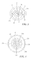
- Figure 3 is a section on the line 3-3 of Figure 1;
- Figure 4 is a section on the line 4-4 of Figure 1;
- Figure 5 is a side view of an alternative embodiment of the pump of the present invention shown in its open position;
- Figure 6 is a front view of Figure 5;
- Figure 7 is a section on the line 8-8 of Figure 5;
- Figure 8 is a section on the line 9-9 of Figure 6; and
- Figure 9 shows the same section as Figure 7, but with the pump in its closed position.
- With reference to said figures, these show, indicated overall by 1, a closable pump for fluid substances withdrawable from a container.
- Known pumps comprise a cup-
shaped body 5 defining an intake, containing andcompression chamber 6 in which a knownpiston 7 is sealedly slidable, driven by astem 2. The cup-shaped body presents at least oneintake hole 8 closed by at least onefirst valve 9 of known type and communicating via a dip tube 10 with the interior of the container on which the pump 1 is mounted. The stem is internally hollow, its cavity communicating via at least onesecond valve 12, also of known type, with thecompression chamber 6. - The
stem 2 is slidably mounted through anendpiece 13 which closes said cup-shaped body 5. More precisely, thestem 2 is guided through theendpiece 13 by acylindrical guide surface 13a thereof. This surface presents aprojection 13b which engages in agroove 2a present in the stem outer surface to make thestem 2 and endpiece 13 torsionally rigid. In this respect, thestem 2 can slide through theendpiece 13 to drive thepiston 7, but cannot rotate about the endpiece, this rotation being prevented by saidprojection 13a. - Mounted on the
stem 2 there is a dispensing pushbutton 4 presenting asecond passage 14 for dispensing the fluid substance and opening towards the outside of said dispensing pushbutton. - Specifically, the
stem 2 presents a flatfirst surface 2b of circular contact section which cooperates by contact with a second contactingsurface 4a of said dispensing pushbutton 4, which is also flat and of circular section (and consequently of complementary shape to the first). The first contactingsurface 2b and the second contactingsurface 4a cooperate frontally and rest against each other when the stem is inserted into the pushbutton. The stem cylindrical surface also presents an undercut 2c which locks the stem in acylindrical hole 4b provided in the pushbutton; slight interference is present between the stem and saidcylindrical hole 4b. - Consequently if a torque is applied to the pushbutton 4, it can rotate relative to the
stem 2 about a longitudinal axis A of thestem 2, coinciding with that of the pushbutton. - In the
stem 2 afirst passage 3 is provided presenting afirst aperture 3a and connecting saidfirst aperture 3a to the cavity in thestem 2. Thepassage 3 is substantially an axial hole provided in a position offset from the stem axis A, theaperture 3a also consequently being offset from this latter. - The
second passage 14 presents a substantially linearfirst portion 14a connected to asecond portion 14 when the pushbutton is mounted on the stem, has its axis substantially parallel to the stem axis A. This second portion 14b presents anaperture 14c at the pushbuttonsecond surface 4a. Thesecond aperture 14c is offset from the axis A, and when the pushbutton is in a first open position thesecond aperture 14c faces and is substantially coaxial with thefirst aperture 3a of thestem 2, so that these apertures communicate and the fluid product can be dispensed by operating the pushbutton. - Advantageously the
first aperture 3a andsecond aperture 14c have identical dimensions and shape. - When the pushbutton is rotated, for example through 90° into a closed position as in Figure 2, the
first aperture 3a and thesecond aperture 14c do not face each other but each of them contact and faces the second contactingsurface 4a and the first contactingsurface 2a respectively. Thefirst aperture 3a is hence closed substantially tightly and the fluid product in the stem cavity and in thefirst passage 3 is isolated from the outside atmosphere. - In that portion coupled to the
stem 2, the dispensing pushbutton 4 presents acylindrical ring 20 which is integral with the pushbutton 4 and from which a pair offirst abutments - The endpiece presents a pair of cylindrical
second abutments slots - When the dispensing pushbutton 4 is in its open position (Figure 1) each of the
first abutments slots slots first abutment - When the pushbutton is in its closed position, each of the
first abutments second abutments - Advantageously, conventional stops (not shown) are provided on the
second abutments first abutments - Figures 5-9 show a preferred embodiment of the present pump. These figures show only a part of the stem and pushbutton, the pump connected to the stem being of any type. The
stem 70 is sealedly inserted in acavity 71 suitably provided in the dispensingpushbutton 72, and is locked in its seat by a snap-actingundercut 73. The undercut enables the pushbutton to rotate about the stem axis. The seal is provided by the contact between the stem outer surface 70b and thatsurface 71 A defining the cavity. The top 70A of thestem 70 is open, at its open top there being laterally provided aU-shaped groove 74 facing anaperture 74A in the lateral outer surface of the stem and also in the upper edge of thestem 70. Thisgroove 74 is functionally similar to thefirst passage 3 of the preceding embodiment. In particular, a groove of this type is easily moulded without the aid of carriers in the plastic moulds, given that it is provided at the top of the piece. It will be noted that top of the stem, although open, sealedly rests against thepushbutton 72. - The dispensing pushbutton comprises a
fluid dispensing passage 76, functionally similar to thesecond passage 14. Thisfluid dispensing passage 76 is a hole which opens at 76A directly onto the lateral surface defining the cavity in which thestem 70 is inserted. - This passage is also easily obtainable by moulding, this time by means of a carrier.
- The operation of this embodiment is entirely similar to the preceding. In this respect, when the stem and pushbutton are in the open position such that the
aperture 74A of the stem groove faces the aperture of the pushbutton passage 76 (Figures 5-7), dispensing is possible. In contrast, when these apertures do not face each other and thestem aperture 74A faces the surface defining the stem cavity while thepassage aperture 76A faces the stem outer surface, dispensing is not possible (Figure 8). - To facilitate alignment between the first and second aperture when the pump is in the open position, in the surface defining the pushbutton cavity a circular arc shaped cut-out 77 is provided, on the stem surface there being provided a
rib 78 which becomes inserted into said cut-out when the stem and pushbutton are coupled. When the pump is open the rib abuts against a first limit stop (Figure 8, Figure 9) defined by a wall of the cut-out, while when the limit stop abuts against the other wall of the cut-out the pump is closed (Figure 7). This solution can also be applied in a totally similar manner to the previously described embodiment. - Advantageously, by means of only a small rotation the aforedescribed embodiment enables a large distance to be created between the apertures, to achieve a more effective closure. Moreover as already stated moulding the stem, which is of plastic material as is the pushbutton, is extremely easy given that no carrier is required in the mould.
- As in the preceding embodiment and in a totally similar manner, abutments can be provided between the endpiece and pushbutton, to limit their movement when the pump is in the closed position. Means can also be provided between the endpiece and stem to make these latter torsionally rigid.
Claims (14)
- A closable dispensing pump (1) for fluid substances withdrawable from a container, comprising a cup-shaped body (5) defining a chamber (6) in which a piston (7) is slidable, drivable by a stem (2), the cup-shaped body presents at least one intake hole (8) closed by at least one first valve (9) and communicating via a dip tube with the interior of the container, said stem (2, 70) presenting in its interior at least one first passage (3, 74) communicating, via at least one second valve (12) with said chamber and being slidably mounted through an endpiece (13) which closes said cup-shaped body (5), and a dispensing pushbutton (4, 72) presenting, for dispensing the fluid substance, a second passage (14, 76) opening towards the outside of said dispensing pushbutton (4), said stem (70) presenting a first contacting surface (2b, 70B) cooperating substantially sealedly and by contact with a second contacting surface (4a, 71A) of said dispensing pushbutton, characterised in that said first passage (3, 74) presents a first aperture (3a, 74A) which opens onto said first contacting surface (2b, 70B), said second passage (14, 76) presenting a second aperture (14c, 76A) which opens onto said second contacting surface (4a, 71A), said pushbutton and said stem being mutually rotatable about a longitudinal axis (A) between at least one open position in which said first and second aperture face each other and are in mutual communication, and a closed position in which they are mutually isolated and displaced.
- A pump as claimed in claim 1, characterised in that said first surface (2a) and second surface (4a) are frontal surfaces of said pushbutton and said stem.
- A pump as claimed in claim 2, characterised in that said first aperture is in a position offset from an axis (A) of said stem (2).
- A pump as claimed in claim 2, characterised in that said second aperture is provided in a position offset from an axis (A) of said dispensing pushbutton (4).
- A pump as claimed in claim 1, characterised in that said first passage (3) is an axial hole provided in a position offset from said stem axis (A).
- A pump as claimed in claim 1, characterised in that said first surface (70B) and second surface (71A) are lateral surfaces of said pushbutton (72) and said stem (70).
- A pump as claimed in claim 6, characterised in that said first passage (74) is a lateral groove provided at the top of the stem, and faces both the upper edge of the stem and, with an aperture (74A), the lateral outer surface (70B) of the stem.
- A pump as claimed in claim 7, characterised in that said top of the stem is open.
- A pump as claimed in claim 6, characterised in that said second passage (76) is a hole which opens directly onto the lateral surface (71A) defining the cavity housing the stem.
- A pump as claimed in claim 1, characterised in that said stem (2, 70) and said endpiece (13) are torsionally rigid.
- A pump as claimed in claim 8, characterised in that said endpiece (13) presents, at a stem guide surface thereof, a projection (13b) cooperating with a grove (2a) provided in the stem.
- A pump as claimed in claim 1, characterised in that said dispensing pushbutton and said endpiece each present at least one abutment (21 a, 21 b, 22a, 22b) which, when the pushbutton is in its closed position, mutually cooperate to block the stroke of said pushbutton and hence of the stem.
- A pump as claimed in claim 2, characterised in that the pushbutton presents a pair of abutments (21 a, 22a) radially projecting from the body of the pushbutton, the endpiece presenting a pair of cylindrical abutments (22a, 22b), each being separated by a pair of grooves (23a, 23b), each of which receives an abutment (21 a, 21 b) of the pushbutton during the pushbutton stroke when the pushbutton is in its open position.
- A pump as claimed in claim 1, characterised in that a cut-out (77) is provided in that surface defining the pushbutton cavity, on the stem surface a rib (78) being provided which becomes inserted into said cut-out when the stem and pushbutton are connected together, said cut-out and said rib cooperating to facilitate alignment between the first and second aperture when the pump is in its open position, and to limit rotation between the pushbutton and stem.
Applications Claiming Priority (1)
| Application Number | Priority Date | Filing Date | Title |
|---|---|---|---|
| IT001561A ITMI20061561A1 (en) | 2006-08-03 | 2006-08-03 | CLOSING DELIVERY PUMP FOR FLUID SUBSTANCES PRELEVABLE BY A CONTAINER |
Publications (2)
| Publication Number | Publication Date |
|---|---|
| EP1884290A1 true EP1884290A1 (en) | 2008-02-06 |
| EP1884290B1 EP1884290B1 (en) | 2009-02-18 |
Family
ID=38582029
Family Applications (1)
| Application Number | Title | Priority Date | Filing Date |
|---|---|---|---|
| EP07112457A Active EP1884290B1 (en) | 2006-08-03 | 2007-07-13 | Closable dispensing pump for fluid substances |
Country Status (6)
| Country | Link |
|---|---|
| US (1) | US20080029550A1 (en) |
| EP (1) | EP1884290B1 (en) |
| AT (1) | ATE422968T1 (en) |
| DE (1) | DE602007000560D1 (en) |
| ES (1) | ES2321344T3 (en) |
| IT (1) | ITMI20061561A1 (en) |
Cited By (2)
| Publication number | Priority date | Publication date | Assignee | Title |
|---|---|---|---|---|
| CN105307948A (en) * | 2013-05-12 | 2016-02-03 | 佳尼雍株式会社 | Push-type dispenser |
| WO2017050834A1 (en) * | 2015-09-23 | 2017-03-30 | Rpc Bramlage Gmbh | Dispenser for liquid to pasty substances |
Families Citing this family (2)
| Publication number | Priority date | Publication date | Assignee | Title |
|---|---|---|---|---|
| WO2015176057A1 (en) * | 2014-05-16 | 2015-11-19 | Renerge, Inc. | Fluid flow induced oscillating energy harvester with variable damping based upon oscillation amplitude |
| CN116078574A (en) | 2018-04-06 | 2023-05-09 | 9421-7213魁北克股份有限公司 | Dispensing pump and method of manufacturing the same |
Citations (5)
| Publication number | Priority date | Publication date | Assignee | Title |
|---|---|---|---|---|
| US2853210A (en) * | 1956-11-13 | 1958-09-23 | Drackett Co | Self-sealing internally vented dispenser pump |
| US4318498A (en) * | 1980-05-12 | 1982-03-09 | Realex Corporation | Uplocking dispensing pump |
| US5492252A (en) * | 1993-10-22 | 1996-02-20 | L'oreal | Dispensing assembly due to control air uptake in contact with fluid product |
| US5617976A (en) * | 1995-03-21 | 1997-04-08 | L'oreal | Dispenser of liquid or pasty product which can be used especially in cosmetics |
| WO2001091911A1 (en) * | 2000-05-26 | 2001-12-06 | Taplast Spa | Bellows pump for delivery of liquids |
Family Cites Families (4)
| Publication number | Priority date | Publication date | Assignee | Title |
|---|---|---|---|---|
| ATE132454T1 (en) * | 1989-07-25 | 1996-01-15 | Oreal | DISPENSING DEVICE FOR AT LEAST ONE LIQUID PRODUCT, IN PARTICULAR OF A COSMETIC OR PHARMACEUTICAL TYPE |
| FR2816375B1 (en) * | 2000-11-07 | 2003-04-11 | Oreal | PUMP FOR DISPENSING A PRODUCT, ESPECIALLY A COSMETIC OR CARE PRODUCT |
| FR2823845B1 (en) * | 2001-04-20 | 2003-10-31 | Rexam Sofab | DEVICE FOR DOSING LIQUID OR GEL PRODUCTS |
| US6695171B2 (en) * | 2002-02-12 | 2004-02-24 | Seaquistperfect Dispensing Foreign, Inc. | Pump dispenser |
-
2006
- 2006-08-03 IT IT001561A patent/ITMI20061561A1/en unknown
-
2007
- 2007-07-13 DE DE602007000560T patent/DE602007000560D1/en active Active
- 2007-07-13 ES ES07112457T patent/ES2321344T3/en active Active
- 2007-07-13 AT AT07112457T patent/ATE422968T1/en not_active IP Right Cessation
- 2007-07-13 EP EP07112457A patent/EP1884290B1/en active Active
- 2007-07-17 US US11/778,985 patent/US20080029550A1/en not_active Abandoned
Patent Citations (5)
| Publication number | Priority date | Publication date | Assignee | Title |
|---|---|---|---|---|
| US2853210A (en) * | 1956-11-13 | 1958-09-23 | Drackett Co | Self-sealing internally vented dispenser pump |
| US4318498A (en) * | 1980-05-12 | 1982-03-09 | Realex Corporation | Uplocking dispensing pump |
| US5492252A (en) * | 1993-10-22 | 1996-02-20 | L'oreal | Dispensing assembly due to control air uptake in contact with fluid product |
| US5617976A (en) * | 1995-03-21 | 1997-04-08 | L'oreal | Dispenser of liquid or pasty product which can be used especially in cosmetics |
| WO2001091911A1 (en) * | 2000-05-26 | 2001-12-06 | Taplast Spa | Bellows pump for delivery of liquids |
Cited By (7)
| Publication number | Priority date | Publication date | Assignee | Title |
|---|---|---|---|---|
| CN105307948A (en) * | 2013-05-12 | 2016-02-03 | 佳尼雍株式会社 | Push-type dispenser |
| CN105307948B (en) * | 2013-05-12 | 2017-10-20 | 佳尼雍株式会社 | Push type dispenser |
| WO2017050834A1 (en) * | 2015-09-23 | 2017-03-30 | Rpc Bramlage Gmbh | Dispenser for liquid to pasty substances |
| CN108025323A (en) * | 2015-09-23 | 2018-05-11 | Rpc布兰姆拉格股份有限公司 | Feeder for liquid to pasta material |
| US10464089B2 (en) | 2015-09-23 | 2019-11-05 | Rpc Bramlage Gmbh | Dispenser for liquid to pasty substances |
| RU2710560C2 (en) * | 2015-09-23 | 2019-12-27 | Рпк Брамлаге Гмбх | Dispenser for masses from liquid to pastelike |
| CN108025323B (en) * | 2015-09-23 | 2021-10-08 | Rpc布兰姆拉格股份有限公司 | Feeder for liquid to pasty materials |
Also Published As
| Publication number | Publication date |
|---|---|
| ITMI20061561A1 (en) | 2008-02-04 |
| DE602007000560D1 (en) | 2009-04-02 |
| US20080029550A1 (en) | 2008-02-07 |
| ES2321344T3 (en) | 2009-06-04 |
| EP1884290B1 (en) | 2009-02-18 |
| ATE422968T1 (en) | 2009-03-15 |
Similar Documents
| Publication | Publication Date | Title |
|---|---|---|
| US5096098A (en) | Pushbutton for actuating a dispenser for semi-liquid substances | |
| US10150126B2 (en) | Cosmetic container capable of storing and discharging two kinds of contents | |
| EP1982929B1 (en) | Airless dispensing pump container with an airtight push down type nozzle head | |
| US4696415A (en) | Apparatus for dispensing products from a self-sealing dispenser | |
| EP1872859B1 (en) | Simplified pump for dispensing fluid substances withdrawn from a container | |
| US6168050B1 (en) | Hand-operated pump with a trigger, for dispensing liquids | |
| PL200833B1 (en) | Dosing device comprising a medium reservoir and corresponding pump device | |
| US20080169312A1 (en) | Dispenser with Sealed Dispensing Valve Unit | |
| US20090302064A1 (en) | Elastomeric dispensing pump that can be made with as few as two components | |
| PL191140B1 (en) | Pump-type dispenser | |
| EP1884290B1 (en) | Closable dispensing pump for fluid substances | |
| RU2248926C2 (en) | Product sample packing and distribution device | |
| US9486056B2 (en) | Cosmetic container capable of storing and discharging two kinds of contents | |
| EP0307127A1 (en) | Collapsible chamber metering valve | |
| US20060065675A1 (en) | Product dispenser comprising a tappet-activated pump | |
| US10821456B2 (en) | Device for dispensing a product with improved triggering | |
| KR20150043362A (en) | Applicator Head for a Dispenser, as well as a Dispenser Comprising such an Applicator Head | |
| US20060231577A1 (en) | Viscous liquid dispensing pump | |
| JP2019506214A (en) | Packaging dispenser for two contents | |
| JP4825678B2 (en) | Fluid product dosing pump | |
| KR102445849B1 (en) | Pump head and metering device | |
| EP0998355B1 (en) | Push-button comprising a movable nozzle for dispensing pressurized fluids | |
| KR20140117832A (en) | Nozzle structure of operation button for liquid cosmetic container of pump type | |
| EP1135310B1 (en) | Multi-piston, ratcheted dispensing device | |
| JP2007505256A (en) | Fluid dispenser pump |
Legal Events
| Date | Code | Title | Description |
|---|---|---|---|
| PUAI | Public reference made under article 153(3) epc to a published international application that has entered the european phase |
Free format text: ORIGINAL CODE: 0009012 |
|
| AK | Designated contracting states |
Kind code of ref document: A1 Designated state(s): AT BE BG CH CY CZ DE DK EE ES FI FR GB GR HU IE IS IT LI LT LU LV MC MT NL PL PT RO SE SI SK TR |
|
| AX | Request for extension of the european patent |
Extension state: AL BA HR MK YU |
|
| RAP1 | Party data changed (applicant data changed or rights of an application transferred) |
Owner name: MEADWESTVACO CALMAR S.R.L. |
|
| 17P | Request for examination filed |
Effective date: 20080616 |
|
| GRAP | Despatch of communication of intention to grant a patent |
Free format text: ORIGINAL CODE: EPIDOSNIGR1 |
|
| AKX | Designation fees paid |
Designated state(s): AT BE BG CH CY CZ DE DK EE ES FI FR GB GR HU IE IS IT LI LT LU LV MC MT NL PL PT RO SE SI SK TR |
|
| GRAS | Grant fee paid |
Free format text: ORIGINAL CODE: EPIDOSNIGR3 |
|
| GRAA | (expected) grant |
Free format text: ORIGINAL CODE: 0009210 |
|
| AK | Designated contracting states |
Kind code of ref document: B1 Designated state(s): AT BE BG CH CY CZ DE DK EE ES FI FR GB GR HU IE IS IT LI LT LU LV MC MT NL PL PT RO SE SI SK TR |
|
| REG | Reference to a national code |
Ref country code: GB Ref legal event code: FG4D |
|
| REG | Reference to a national code |
Ref country code: CH Ref legal event code: EP |
|
| REG | Reference to a national code |
Ref country code: IE Ref legal event code: FG4D |
|
| REF | Corresponds to: |
Ref document number: 602007000560 Country of ref document: DE Date of ref document: 20090402 Kind code of ref document: P |
|
| REG | Reference to a national code |
Ref country code: ES Ref legal event code: FG2A Ref document number: 2321344 Country of ref document: ES Kind code of ref document: T3 |
|
| PG25 | Lapsed in a contracting state [announced via postgrant information from national office to epo] |
Ref country code: FI Free format text: LAPSE BECAUSE OF FAILURE TO SUBMIT A TRANSLATION OF THE DESCRIPTION OR TO PAY THE FEE WITHIN THE PRESCRIBED TIME-LIMIT Effective date: 20090218 Ref country code: SI Free format text: LAPSE BECAUSE OF FAILURE TO SUBMIT A TRANSLATION OF THE DESCRIPTION OR TO PAY THE FEE WITHIN THE PRESCRIBED TIME-LIMIT Effective date: 20090218 Ref country code: LT Free format text: LAPSE BECAUSE OF FAILURE TO SUBMIT A TRANSLATION OF THE DESCRIPTION OR TO PAY THE FEE WITHIN THE PRESCRIBED TIME-LIMIT Effective date: 20090218 Ref country code: NL Free format text: LAPSE BECAUSE OF FAILURE TO SUBMIT A TRANSLATION OF THE DESCRIPTION OR TO PAY THE FEE WITHIN THE PRESCRIBED TIME-LIMIT Effective date: 20090218 |
|
| NLV1 | Nl: lapsed or annulled due to failure to fulfill the requirements of art. 29p and 29m of the patents act | ||
| PG25 | Lapsed in a contracting state [announced via postgrant information from national office to epo] |
Ref country code: PL Free format text: LAPSE BECAUSE OF FAILURE TO SUBMIT A TRANSLATION OF THE DESCRIPTION OR TO PAY THE FEE WITHIN THE PRESCRIBED TIME-LIMIT Effective date: 20090218 Ref country code: SE Free format text: LAPSE BECAUSE OF FAILURE TO SUBMIT A TRANSLATION OF THE DESCRIPTION OR TO PAY THE FEE WITHIN THE PRESCRIBED TIME-LIMIT Effective date: 20090518 Ref country code: AT Free format text: LAPSE BECAUSE OF FAILURE TO SUBMIT A TRANSLATION OF THE DESCRIPTION OR TO PAY THE FEE WITHIN THE PRESCRIBED TIME-LIMIT Effective date: 20090218 Ref country code: IS Free format text: LAPSE BECAUSE OF FAILURE TO SUBMIT A TRANSLATION OF THE DESCRIPTION OR TO PAY THE FEE WITHIN THE PRESCRIBED TIME-LIMIT Effective date: 20090618 Ref country code: LV Free format text: LAPSE BECAUSE OF FAILURE TO SUBMIT A TRANSLATION OF THE DESCRIPTION OR TO PAY THE FEE WITHIN THE PRESCRIBED TIME-LIMIT Effective date: 20090218 |
|
| PG25 | Lapsed in a contracting state [announced via postgrant information from national office to epo] |
Ref country code: BE Free format text: LAPSE BECAUSE OF FAILURE TO SUBMIT A TRANSLATION OF THE DESCRIPTION OR TO PAY THE FEE WITHIN THE PRESCRIBED TIME-LIMIT Effective date: 20090218 |
|
| PG25 | Lapsed in a contracting state [announced via postgrant information from national office to epo] |
Ref country code: PT Free format text: LAPSE BECAUSE OF FAILURE TO SUBMIT A TRANSLATION OF THE DESCRIPTION OR TO PAY THE FEE WITHIN THE PRESCRIBED TIME-LIMIT Effective date: 20090727 Ref country code: EE Free format text: LAPSE BECAUSE OF FAILURE TO SUBMIT A TRANSLATION OF THE DESCRIPTION OR TO PAY THE FEE WITHIN THE PRESCRIBED TIME-LIMIT Effective date: 20090218 Ref country code: DK Free format text: LAPSE BECAUSE OF FAILURE TO SUBMIT A TRANSLATION OF THE DESCRIPTION OR TO PAY THE FEE WITHIN THE PRESCRIBED TIME-LIMIT Effective date: 20090218 Ref country code: CZ Free format text: LAPSE BECAUSE OF FAILURE TO SUBMIT A TRANSLATION OF THE DESCRIPTION OR TO PAY THE FEE WITHIN THE PRESCRIBED TIME-LIMIT Effective date: 20090218 |
|
| PG25 | Lapsed in a contracting state [announced via postgrant information from national office to epo] |
Ref country code: SK Free format text: LAPSE BECAUSE OF FAILURE TO SUBMIT A TRANSLATION OF THE DESCRIPTION OR TO PAY THE FEE WITHIN THE PRESCRIBED TIME-LIMIT Effective date: 20090218 Ref country code: RO Free format text: LAPSE BECAUSE OF FAILURE TO SUBMIT A TRANSLATION OF THE DESCRIPTION OR TO PAY THE FEE WITHIN THE PRESCRIBED TIME-LIMIT Effective date: 20090218 |
|
| PLBE | No opposition filed within time limit |
Free format text: ORIGINAL CODE: 0009261 |
|
| STAA | Information on the status of an ep patent application or granted ep patent |
Free format text: STATUS: NO OPPOSITION FILED WITHIN TIME LIMIT |
|
| 26N | No opposition filed |
Effective date: 20091119 |
|
| PG25 | Lapsed in a contracting state [announced via postgrant information from national office to epo] |
Ref country code: BG Free format text: LAPSE BECAUSE OF FAILURE TO SUBMIT A TRANSLATION OF THE DESCRIPTION OR TO PAY THE FEE WITHIN THE PRESCRIBED TIME-LIMIT Effective date: 20090518 |
|
| PG25 | Lapsed in a contracting state [announced via postgrant information from national office to epo] |
Ref country code: MC Free format text: LAPSE BECAUSE OF NON-PAYMENT OF DUE FEES Effective date: 20090731 |
|
| PG25 | Lapsed in a contracting state [announced via postgrant information from national office to epo] |
Ref country code: IE Free format text: LAPSE BECAUSE OF NON-PAYMENT OF DUE FEES Effective date: 20090713 |
|
| PG25 | Lapsed in a contracting state [announced via postgrant information from national office to epo] |
Ref country code: GR Free format text: LAPSE BECAUSE OF FAILURE TO SUBMIT A TRANSLATION OF THE DESCRIPTION OR TO PAY THE FEE WITHIN THE PRESCRIBED TIME-LIMIT Effective date: 20090519 |
|
| PG25 | Lapsed in a contracting state [announced via postgrant information from national office to epo] |
Ref country code: LU Free format text: LAPSE BECAUSE OF NON-PAYMENT OF DUE FEES Effective date: 20090713 |
|
| PG25 | Lapsed in a contracting state [announced via postgrant information from national office to epo] |
Ref country code: HU Free format text: LAPSE BECAUSE OF FAILURE TO SUBMIT A TRANSLATION OF THE DESCRIPTION OR TO PAY THE FEE WITHIN THE PRESCRIBED TIME-LIMIT Effective date: 20090819 |
|
| PG25 | Lapsed in a contracting state [announced via postgrant information from national office to epo] |
Ref country code: TR Free format text: LAPSE BECAUSE OF FAILURE TO SUBMIT A TRANSLATION OF THE DESCRIPTION OR TO PAY THE FEE WITHIN THE PRESCRIBED TIME-LIMIT Effective date: 20090218 |
|
| PG25 | Lapsed in a contracting state [announced via postgrant information from national office to epo] |
Ref country code: CY Free format text: LAPSE BECAUSE OF FAILURE TO SUBMIT A TRANSLATION OF THE DESCRIPTION OR TO PAY THE FEE WITHIN THE PRESCRIBED TIME-LIMIT Effective date: 20090218 |
|
| REG | Reference to a national code |
Ref country code: CH Ref legal event code: PL |
|
| PG25 | Lapsed in a contracting state [announced via postgrant information from national office to epo] |
Ref country code: LI Free format text: LAPSE BECAUSE OF NON-PAYMENT OF DUE FEES Effective date: 20110731 Ref country code: CH Free format text: LAPSE BECAUSE OF NON-PAYMENT OF DUE FEES Effective date: 20110731 |
|
| PGFP | Annual fee paid to national office [announced via postgrant information from national office to epo] |
Ref country code: ES Payment date: 20120706 Year of fee payment: 6 |
|
| PGFP | Annual fee paid to national office [announced via postgrant information from national office to epo] |
Ref country code: DE Payment date: 20130723 Year of fee payment: 7 |
|
| PGFP | Annual fee paid to national office [announced via postgrant information from national office to epo] |
Ref country code: FR Payment date: 20130726 Year of fee payment: 7 |
|
| REG | Reference to a national code |
Ref country code: DE Ref legal event code: R119 Ref document number: 602007000560 Country of ref document: DE |
|
| REG | Reference to a national code |
Ref country code: FR Ref legal event code: ST Effective date: 20150331 |
|
| PG25 | Lapsed in a contracting state [announced via postgrant information from national office to epo] |
Ref country code: DE Free format text: LAPSE BECAUSE OF NON-PAYMENT OF DUE FEES Effective date: 20150203 |
|
| REG | Reference to a national code |
Ref country code: DE Ref legal event code: R119 Ref document number: 602007000560 Country of ref document: DE Effective date: 20150203 |
|
| PG25 | Lapsed in a contracting state [announced via postgrant information from national office to epo] |
Ref country code: FR Free format text: LAPSE BECAUSE OF NON-PAYMENT OF DUE FEES Effective date: 20140731 |
|
| REG | Reference to a national code |
Ref country code: ES Ref legal event code: FD2A Effective date: 20160226 |
|
| PG25 | Lapsed in a contracting state [announced via postgrant information from national office to epo] |
Ref country code: ES Free format text: LAPSE BECAUSE OF NON-PAYMENT OF DUE FEES Effective date: 20140714 |
|
| PGFP | Annual fee paid to national office [announced via postgrant information from national office to epo] |
Ref country code: IT Payment date: 20210721 Year of fee payment: 15 |
|
| PGFP | Annual fee paid to national office [announced via postgrant information from national office to epo] |
Ref country code: GB Payment date: 20210727 Year of fee payment: 15 |
|
| GBPC | Gb: european patent ceased through non-payment of renewal fee |
Effective date: 20220713 |
|
| PG25 | Lapsed in a contracting state [announced via postgrant information from national office to epo] |
Ref country code: GB Free format text: LAPSE BECAUSE OF NON-PAYMENT OF DUE FEES Effective date: 20220713 |