EP1884269A2 - Swing device and control method for a swing device - Google Patents
Swing device and control method for a swing device Download PDFInfo
- Publication number
- EP1884269A2 EP1884269A2 EP07014103A EP07014103A EP1884269A2 EP 1884269 A2 EP1884269 A2 EP 1884269A2 EP 07014103 A EP07014103 A EP 07014103A EP 07014103 A EP07014103 A EP 07014103A EP 1884269 A2 EP1884269 A2 EP 1884269A2
- Authority
- EP
- European Patent Office
- Prior art keywords
- swing member
- swing
- driving
- user
- fulcrum
- Prior art date
- Legal status (The legal status is an assumption and is not a legal conclusion. Google has not performed a legal analysis and makes no representation as to the accuracy of the status listed.)
- Withdrawn
Links
Images







Classifications
-
- A—HUMAN NECESSITIES
- A63—SPORTS; GAMES; AMUSEMENTS
- A63G—MERRY-GO-ROUNDS; SWINGS; ROCKING-HORSES; CHUTES; SWITCHBACKS; SIMILAR DEVICES FOR PUBLIC AMUSEMENT
- A63G19/00—Toy animals for riding
- A63G19/20—Toy animals for riding motor-driven
-
- A—HUMAN NECESSITIES
- A63—SPORTS; GAMES; AMUSEMENTS
- A63F—CARD, BOARD, OR ROULETTE GAMES; INDOOR GAMES USING SMALL MOVING PLAYING BODIES; VIDEO GAMES; GAMES NOT OTHERWISE PROVIDED FOR
- A63F13/00—Video games, i.e. games using an electronically generated display having two or more dimensions
- A63F13/25—Output arrangements for video game devices
- A63F13/28—Output arrangements for video game devices responding to control signals received from the game device for affecting ambient conditions, e.g. for vibrating players' seats, activating scent dispensers or affecting temperature or light
-
- A—HUMAN NECESSITIES
- A63—SPORTS; GAMES; AMUSEMENTS
- A63F—CARD, BOARD, OR ROULETTE GAMES; INDOOR GAMES USING SMALL MOVING PLAYING BODIES; VIDEO GAMES; GAMES NOT OTHERWISE PROVIDED FOR
- A63F13/00—Video games, i.e. games using an electronically generated display having two or more dimensions
- A63F13/80—Special adaptations for executing a specific game genre or game mode
- A63F13/803—Driving vehicles or craft, e.g. cars, airplanes, ships, robots or tanks
-
- A—HUMAN NECESSITIES
- A63—SPORTS; GAMES; AMUSEMENTS
- A63G—MERRY-GO-ROUNDS; SWINGS; ROCKING-HORSES; CHUTES; SWITCHBACKS; SIMILAR DEVICES FOR PUBLIC AMUSEMENT
- A63G31/00—Amusement arrangements
- A63G31/16—Amusement arrangements creating illusions of travel
-
- G—PHYSICS
- G09—EDUCATION; CRYPTOGRAPHY; DISPLAY; ADVERTISING; SEALS
- G09B—EDUCATIONAL OR DEMONSTRATION APPLIANCES; APPLIANCES FOR TEACHING, OR COMMUNICATING WITH, THE BLIND, DEAF OR MUTE; MODELS; PLANETARIA; GLOBES; MAPS; DIAGRAMS
- G09B9/00—Simulators for teaching or training purposes
- G09B9/02—Simulators for teaching or training purposes for teaching control of vehicles or other craft
-
- G—PHYSICS
- G09—EDUCATION; CRYPTOGRAPHY; DISPLAY; ADVERTISING; SEALS
- G09B—EDUCATIONAL OR DEMONSTRATION APPLIANCES; APPLIANCES FOR TEACHING, OR COMMUNICATING WITH, THE BLIND, DEAF OR MUTE; MODELS; PLANETARIA; GLOBES; MAPS; DIAGRAMS
- G09B9/00—Simulators for teaching or training purposes
- G09B9/02—Simulators for teaching or training purposes for teaching control of vehicles or other craft
- G09B9/08—Simulators for teaching or training purposes for teaching control of vehicles or other craft for teaching control of aircraft, e.g. Link trainer
- G09B9/12—Motion systems for aircraft simulators
- G09B9/14—Motion systems for aircraft simulators controlled by fluid actuated piston or cylinder ram
-
- A—HUMAN NECESSITIES
- A63—SPORTS; GAMES; AMUSEMENTS
- A63F—CARD, BOARD, OR ROULETTE GAMES; INDOOR GAMES USING SMALL MOVING PLAYING BODIES; VIDEO GAMES; GAMES NOT OTHERWISE PROVIDED FOR
- A63F2300/00—Features of games using an electronically generated display having two or more dimensions, e.g. on a television screen, showing representations related to the game
- A63F2300/30—Features of games using an electronically generated display having two or more dimensions, e.g. on a television screen, showing representations related to the game characterized by output arrangements for receiving control signals generated by the game device
- A63F2300/302—Features of games using an electronically generated display having two or more dimensions, e.g. on a television screen, showing representations related to the game characterized by output arrangements for receiving control signals generated by the game device specially adapted for receiving control signals not targeted to a display device or game input means, e.g. vibrating driver's seat, scent dispenser
-
- A—HUMAN NECESSITIES
- A63—SPORTS; GAMES; AMUSEMENTS
- A63F—CARD, BOARD, OR ROULETTE GAMES; INDOOR GAMES USING SMALL MOVING PLAYING BODIES; VIDEO GAMES; GAMES NOT OTHERWISE PROVIDED FOR
- A63F2300/00—Features of games using an electronically generated display having two or more dimensions, e.g. on a television screen, showing representations related to the game
- A63F2300/80—Features of games using an electronically generated display having two or more dimensions, e.g. on a television screen, showing representations related to the game specially adapted for executing a specific type of game
- A63F2300/8017—Driving on land or water; Flying
Definitions
- the present invention relates to a swing device in which a swing member on which a user rides is allowed to swing to thereby make the user sense a rising or lowering feeling and the like, and a control method therefor.
- the present invention relates to a swing device with which a user can body-sense a rising or lowering feeling that can be felt while a moving object such as an aircraft, a ship, a vehicle, or an animal is in a rising or lowering movement, and a control method therefor.
- a structure in which the swing member on which a seat, a steering rod, and the like are mounted is supported by a fulcrum placed on the front side of the seat and two driving points on the rear side of the seat, and the driving points are moved vertically, to thereby change a tilt angle of the swing member with respect to a horizontal plain.
- both of the driving points are moved downward to tilt the swing member in a direction in which the user faces upward, thereby the user can body-sense a rising feeling.
- both of the driving points are moved upward to tilt the swing member in a direction in which the user faces downward, thereby the user can body-sense a lowering feeling.
- the present invention has been made to solve the above-mentioned problem and therefore it is an object of the present invention to provide a swing machine which is able to make a user body-sense a rising or lowering and/or turning feeling more impressively or with higher reality with a simple structure
- the present invention relates to a swing device including:
- the inventors of the present invention have conducted extensive studies about the structures of the conventional game machines such as one disclosed in Japanese Utility Model Application Laid-open No. Hei 3-107993 , and found the reason why it has been difficult to further enhance impression or heighten reality of the rising or lowering feeling, to thereby complete the present invention.
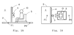
- FIGS. 1A and 1B a plan view and a side view of which are shown in FIGS. 1A and 1B,.
- an operation portion 3 a display device 4 and a seat 5 on which a user O can sit are mounted on a swing member 2 swingably supported at two support points P0 and P1.
- a moving mode of a virtual moving object e.g., fighter aircraft; hereinafter, sometimes simply referred to as moving object
- a video image of the moving object in the virtual space is displayed on the display device 4.
- the support point P1 on a front side of a riding position of the user O serves as a fulcrum whose movement in a vertical direction is regulated
- the support point P0 on the rear side of the riding position of the user O serves as a driving point which is moved in the vertical direction.
- the driving point P0 is driven downward so as to tilt the swing member 2 in a direction in which the user faces upward as represented by a dotted line of FIG. 2A.
- the vertical position of the user O is lowered by an amount represented by reference symbol H.
- the similar situation also occurs in a case where an operation is performed so as to lower the moving object.
- the driving point P0 is driven upward.
- the swing member 2 tilts in a direction in which the user O faces downward, and at the same time, the vertical position of the user is heightened.
- the user senses a rising feeling as well as a lowering feeling, which causes the result that the lowering feeling, which is originally intended to be attained, is cancelled.
- the above-mentioned problems are solved by a constitution, as shown in FIG. 2B, that the support point P0 on the rear side of the riding position of the user O serves as the fulcrum whose movement in the vertical direction is regulated, and the support point P1 apart from the fulcrum P0 in a longitudinal direction (forward direction in the example shown in FIG. 2B) serves as a first driving point which is moved in the vertical direction.
- the first driving point P1 on the front side is driven upward so as to tilt the swing member 2 in the direction in which the user O faces upward as represented by a dotted line of FIG. 2B.
- the vertical position of the user O is heightened by an amount represented by reference symbol H.
- the user senses a rising feeling because his/her body faces upward, and simultaneously senses another rising feeling because his/her body is moved upward, thereby the synergistic effect of which significantly enhances impression or reality of the rising feeling.
- the similar situation also occurs in a case where the operation to lower the moving object is performed.
- the driving point P1 on the front side is driven downward to tilt the swing member 2 in the direction in which the user O faces downward.
- the vertical position of the user is lowered.
- the user senses a lowering feeling because his/her body faces downward, and simultaneously senses another lowering feeling because his/her body is moved downward, thereby a synergistic effect of which significantly enhances impression or reality of the lowering feeling.
- the effects of the present invention is attained by changing the tilt angle of the swing member 2 by rotating the swing member 2 about the fulcrum P0 placed at the rear side of the riding position of the user O and therefore, the vertical movement of the fulcrum P0 needs to be regulated to a certain extent.
- a structure can also be employed in which the fulcrum P0 moves vertically by an amount in a range sufficiently small with respect to the vertical movement of the first driving point P1.
- the first driving point P1 in the swing device of the present invention is spaced apart from the fulcrum P0 by a predetermined amount in the longitudinal direction. Therefore, even in a case where the first driving point P1 is placed on the rear side of the fulcrum P0 as shown in FIG. 2C, the effects of the present invention can also be attained by the mechanism similar to that explained with respect to FIG. 2B. Note that from a viewpoint of a space efficiency or the like, it is preferable that the first driving point P1 be placed on the front side of the fulcrum P0, especially on the front side of the riding position of the user as shown in FIG. 2B.
- the swing device of the present invention can be used for the body-sensible game machine 1 with which the user steers the virtual moving object while enjoying such a feeling that the user actually rides on the moving object.
- the swing device of the present invention can also be used for a body-sensible video image appreciation device with which a user watches a video image from a viewpoint of a moving object with enjoying such a feeling that the user actually rides on the moving object.
- the swing device of the present invention can be applied to arbitrary device which is intended to make a user body-sense a rising feeling, a lowering feeling, or the like.
- the swing member of the present invention is necessary to have a strength and a size allowing the user to ride on, and a shape thereof may be a plate-like shape as shown in FIGS 1A, 1B and 2A to 2C.
- the shape may be a three-dimensional shape such as a shape of a fighter aircraft or a shape of a cockpit thereof.
- the fulcrum support mechanism and the first driving mechanism of the present invention are necessary to be ones for swingably supporting the swing member.
- Examples of the support mechanism for swingably supporting the swing member include a universal joint and a ball joint.
- An arbitrary mechanism capable of driving the first driving point P1 in a vertical direction such as an oil hydraulic cylinder, can be employed as the first driving mechanism of the present invention.
- a linear actuator excellent in a driving length, driving velocity, driving force, and so on, is particularly preferably employed.
- the driving force be applied in a tangential direction with respect to the sphere.
- a driving direction by the first driving mechanism is made always orthogonal to the line segment connecting the fulcrum P0 and the first driving point P1
- the angle formed by a driving direction of the first driving mechanism and the above-mentioned line segment changes as the first driving point P1 moves on a surface of the sphere whose radius corresponds to the line segment. Therefore, a mechanism, such as a cylinder, which performs linear movement cannot constantly perform tangential movement to the sphere surface in reality.
- an operational direction of a supporting force by the first driving mechanism is orthogonal to the line connecting the fulcrum P0 and the first driving point P1 in a reference state (e.g., a state of starting or finishing a game in the embodiment to be described later, or a state where the moving object is in level flight in the virtual space).
- a reference state e.g., a state of starting or finishing a game in the embodiment to be described later, or a state where the moving object is in level flight in the virtual space.
- the riding position refers to a position of the user on the swing member in the operational state, i.e. while the first driving point is driven by the first driving mechanism.
- the riding position of the present invention corresponds to the position of the seat.
- the seat is not always necessarily provided to realize the present application.
- the seat is not necessarily provided in a case where anti-drop means for preventing a user standing upright from dropping from the swing member is provided.
- the terms indicating the directions of forward, backward, left, and right are used based on which direction the user faces in the operational state, that is, while the first driving point is driven by the first driving mechanism.
- the forward direction refers to the direction that the user faces
- the backward direction refers to a reverse direction thereof
- the left and right directions indicate the directions orthogonal to the front and rear directions in the horizontal plane.
- the present invention preferably relates to a swing device further including:
- the second aspect of the present invention is characterized by including the second driving mechanism for driving the second driving point in the vertical direction, the second driving point spaced apart from the fulcrum in the longitudinal direction and spaced apart from the first drive means in the lateral direction.
- the second aspect of the present invention by raising or lowering the first and second driving points simultaneously, similarly to the first aspect of the present invention, it is possible to make the user body-sense a rising/lowering feeling.
- the first and second driving points by vertically driving the first and second driving points in a manner that the their heights are different to each other, it is also possible to make the user body-sense a turning feeling to the left or right of the virtual moving object moving in the virtual space, or a combined feeling of a turning feeling to the left or right and a rising/lowering feeling thereof.
- the swing device further include:
- a line connecting the fulcrum and the support shaft serves as an axial center of the swing member and the degree of freedom of the movement of the swing member is limited to the raising and lowering movement of the axial center along the guide hole and the rotational movement of the swing member about the axial center.
- the support shaft be positioned such that the distances therefrom to the first and second driving points are the same.
- the driving point is placed on a front side of the riding position of the user in the longitudinal direction of the swing member (fourth aspect).
- the entire device can be made compact in the case the driving points are placed on the front side of the seat of the user.
- the swing device further include:
- the user can recognize the movement mode of the moving object determined by the processing means based on the operation that the user performs by himself/herself. Accordingly, it is possible to make the user body-sense a rising, lowering or turning feeling, or the like with higher reality by activating the first driving mechanism according to the movement mode of the moving object, e.g., in the case where the moving object rises, the first driving point is driven so as to raise the front portion of the swing member, and in the case where the moving object lowers, the first driving point is driven so as to lower the front portion of the swing member.
- the swing device further include:
- the first driving mechanism is operated according to the movement mode of the moving object or the virtual viewpoint recognized by the user based on the video image displayed by the display device.
- the video movie can be a video image of a real moving object moving in a real space, a video image of a landscape, an animation video image or a video image created using computer graphics.
- the first driving mechanism can be operated according to the movement mode of the real or virtual moving object or the real or virtual viewpoint (video camera) recorded in the recording means in advance.
- the movement mode of the virtual moving object or the virtual viewpoint can be determined based on data used for creating the computer graphics, and the first driving mechanism can be operated according to the determined movement mode.
- the display device of the sixth aspect of the present invention may be mounted at a position in front of the riding position of the user on the swing member as shown in FIGS. 1A, 1B and 2A to 2C, or at a position in front of the swing member spaced apart therefrom.
- a liquid crystal monitor which is lighter in weight and has a higher resistance against vibration than other display devices such as a CRT, is preferably used.
- each of the first and second driving mechanism is preferably placed orthogonal to a line connecting the fulcrum and the first and second driving points, respectively, while the swing member is placed at a reference position (seventh aspect).
- each of the first and second driving mechanisms be positioned in a tangential direction with respect to each of the spheres.
- support stages of the first and second driving mechanisms are spaced apart from each other, with an disadvantageous result that a width of the entire game machine becomes larger.
- the first and second driving mechanisms of the present invention are positioned such that each the operational direction of the driving mechanisms is orthogonal to the line connecting the fulcrum P0 and the driving points P1 in a reference state of the swing member (e.g., a state where the swing member is placed at a standard position).
- a reference state of the swing member e.g., a state where the swing member is placed at a standard position.
- the present invention relates to a control method for a swing device, the swing device comprising:
- the user can recognize the movement mode of the moving object determined by the processing means based on the operation that the user performs by himself/herself. Accordingly, the effect similar to that of the fifth aspect of the present invention can be attained.
- the present invention relates to a control method for a swing device, the swing device comprising:
- the user can recognize the movement mode of the moving object or the virtual viewpoint based on the video image displayed on the display device. Accordingly, the effect similar to that of the sixth aspect of the present invention can be attained.
- the eighth and ninth aspects of the present invention may include additional structures like in the second to seventh aspects of the present invention, in which a swing member further including a second driving mechanism for driving a second driving point spaced apart from a fulcrum in the longitudinal direction and spaced apart from the first driving point in the lateral direction is used, or the first and second driving mechanisms are operated so that a front portion of the swing member rises or lowers according to the rising or the lowering of the virtual moving object or the virtual viewpoint.
- a body-sensible swing game machine 1 as an example in which a movement mode of a virtual moving object M (e.g., fighter aircraft) in a virtual space is determined based on an operation with respect to an operation member and the determined movement mode is displayed on a display device.
- a virtual moving object M e.g., fighter aircraft
- FIG. 3 is a perspective view illustrating an outer structure of the swing game machine 1 to which a swing device of the present invention is applied
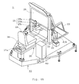
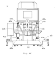
- FIGS. 4A to 4D are perspective, side, front, and rear views, respectively, illustrating the swing game machine 1 from which a casing frame is removed.
- the swing game machine 1 mainly includes a base stage 10, a swing member 20, a fulcrum support mechanism 30, a driving mechanism storing unit 40, and a money processing machine 60.
- the base stage 10 serves as a seating to which the fulcrum support mechanism 30, a first driving mechanism 41a, a second driving mechanism 41b, a static determinate maintaining mechanism 50, and so on to be described later are provided.
- a control unit 80 for controlling an operation of the game machine 1 various connection cables, and the like can be stored.
- the base stage 10 is unnecessary in a case where the fulcrum support mechanism 30, the first driving mechanism 41a, the second driving mechanism 41b, the static determinate maintaining mechanism 50, and the like are directly installed on a floor surface of a facility in which the game machine 1 is installed.
- the swing member 20 includes a floor member 21 extending in a longitudinal direction, a mounting stage 22 provided to a front portion of the floor member 21, a reinforcing frame 23, and so on.
- a seat 24 having a shape similar to a cockpit of a fighter aircraft is provided.
- an operation panel 25 for receiving from a user various game operations is provided and a display device 26 supported by the reinforcing frame 23 are provided.
- the operation panel 25 includes a steering rod 25a being an operation member with which the user instructs a movement direction and the like of the moving object M. By operating the steering rod 25a in forward and backward directions, the moving object M can be raised and lowered, and by operating the steering rod 25a in left and right directions, the moving object M can be turned left and right.
- the operation panel 25 further includes operation members 25b and 25c with which a game is started, items of the game are selected, and other operations are performed. Further, an auxiliary operation member 25d is arranged at a side of the seat 24.
- the display device 26 displays a video image showing a movement mode of the moving object M in the virtual space, which is operated by the user.
- the video image can be an arbitrary video image with which the user can recognize the movement mode of the moving object M. Examples thereof includes a video image of the moving object M observed from a viewpoint fixed in the virtual space, and a video image of the moving object M observed from a viewpoint inside or behind the moving object M, which is movable in the virtual space together with the moving object M while maintaining a predetermined positional relation therewith.
- a liquid crystal monitor which is highly resistant to vibration compared to other display devices such as a CRT, is preferably used.
- the liquid crystal monitor is light in weight, the display device 26 having a large screen size as shown in the figures can be used. Therefore, a game image with a visual impact can be displayed.
- the swing member 20 is supported by a mechanism to be described later in such a manner that the swing member 20 is spaced apart from the base stage 10 by a predetermined distance so as to enable the swing member 20 to perform movements including rolling and pitching.
- the fulcrum support mechanism 30 is arranged at a position spaced apart from the seat 24 being a riding position of the user of the swing member 20 by a predetermined distance therebehind.
- FIG. 5A is an enlarged sectional view illustrating the fulcrum support mechanism 30.
- the fulcrum support mechanism 30 includes: a support column 31 having a square pole shape and projecting upright on the base stage 10; a boll joint 32 fixed to an upper end of the support column 31; a fixation block 33 provided to the floor member 21 so as to cover an opening 21a defined in the floor member 21, and having a square-C-shaped space for storing the ball joint 32 therein; and a cover 34 for covering an upper portion of the fixation block 33.
- the ball joint 32 includes: a shaft bearing member 32a having a sphere-shaped space defined therein; a ball portion 32b rotatably received and held in the sphere-shaped space; and a ball shaft 32c having an end to which the ball portion 32b is attached. The other end of the ball shaft 32c is inserted and fixed to an insertion hole 33a defined in a ceiling of the fixation block 33 with a nut or the like.
- the swing member 20 is swingably supported on the support column 31 so that the ball portion 32b of the ball joint 32 serves as an unmovable fulcrum.
- the driving mechanism storing unit 40 located in a front portion of the game machine 1, the first driving mechanism 41a, the second driving mechanism 41b, and the static determinate maintaining mechanism 50 are stored.
- the first and second driving mechanism 41b, 41b include: support stages 42a and 42b provided on left and right portions of an upper front portion of the base stage 10; universal joints 43a and 43b provided at the upper ends of the support stages 42a and 42b; electric linear actuators 44a and 44b provided to the universal joints 43a and 43b; and universal joints 45a and 45b provided to the tip ends of operation rods of the electric linear actuators 44a and 44b, respectively.
- the universal joints 45a and 45b support the swing member 20 at pads 23a and 23b fixed to mounting bases of the reinforcing frame 23, which is mounted to the mounting stage 22.
- the distance from the pad 23a to the ball portion 32b of the ball joint 32 being the fulcrum of the swing member 20 is the same as the distance from the pad 23b to the ball portion 32b.
- the support stages 42a and 42b are provided so that the axial directions of the electric linear actuators 44a and 44b in a stand-by state are substantially orthogonal to the lines connecting the ball portion 32b being the fulcrum of the swing member 20 and the pads 23a and 23b, respectively.
- the universal joints 43a, 43b, 45a, and 45b are similarly structured, and an enlarged explanatory view illustrating the structure thereof is shown in FIG. 5B.
- each of the universal joints 43a, 43b, 45a, and 45b includes: a cross shaft 43x having two shaft members 43x 1 and 43x 2 orthogonally crossed and fixed to each other; a lower plate 43y having on an upper surface thereof a pair of shaft bearing portions 43y 1 for rotatably supporting both ends of one shaft member 43 x 1 ; and an upper plate 43z having on a lower surface thereof a pair of shaft bearing portions 43z 1 for rotatably supporting both ends of the other shaft member 43 x 2 .
- a member provided to an upper surface of the upper plate 43z is swingably supported with respect to a member provided to a lower surface of the lower plate 43y.
- FIG. 5C is an explanatory view illustrating a structure of the electric linear actuators 44a and 44b.
- each of the electric linear actuators 44a and 44b mainly includes in a cylinder-shaped casing 44 1 ; a servo motor 44 2 ; a boll screw shaft 44 3 rotationally driven by the servo motor 44 2 ; a ball circulation nut 44 4 screwed by the boll screw shaft 44 3 and prohibited to rotate together with the boll screw shaft 44 3 ; and an operation rod 44 5 integrally fixed to the ball circulation nut 44 4 .
- the ball circulation nut 44 4 converts a rotational movement of the boll screw shaft 44 3 by the servo motor 44 2 into a liner movement, thereby driving the operation rod 44 5 forward and backward in the shaft direction thereof.
- the swing member 20 is swingably supported by the universal joints 45a and 45b via the pads 23a and 23b being driving points, and is driven so as to be vertically moved by the forward and backward movement of the operation rod 44 5 of the electric linear actuators 44a and 44b.
- the static determinate maintaining mechanism 50 includes: a support shaft 51 projectingly provided to the reinforcing frame 23 at a midst position between the pads 23a and 23b being the driving points of the swing member 20; a support stage 52 provided on a front portion of an upper surface of the base stage 10 and a guide frame 53 provided on the upper surface of the support stage 52 with a predetermined slant angle and having a guide hole 53a, in which the support shaft 51 is rotatably inserted, for guiding the support shaft 51 only in the vertical direction.
- the support shaft 51 is provided in such a manner that an axial center thereof directs the ball portion 32b being the fulcrum of the swing member 20.
- the support shaft 51 is guided by the guide hole 53a, whereby the degree of freedom of the movement of the swing member 20 is limited to the vertical movement along the guide hole 53a of the support shaft 51 (pitching), and the rotational movement of the swing member 20 about the support shaft 51 (rolling).
- static determinate of the swing member 20 is prevented from being lost while the swing member 20 is driven by the electric linear actuators 44a and 44b,.
- the money processing machine 60 includes: a coin insertion opening 61 defined in an outer surface of the casing, for receiving a game fee; and a coin processing unit 62 provided inside the casing, for detecting an inserted coin and transmitting a coin detection signal to the control unit 80.
- FIG. 6 is a block diagram illustrating a configuration of the control unit 80 of the swing game machine 1.
- control unit 80 includes a main game board 81, an interface I/O board (JVS I/O BD) 82, a solid state relay (SSR) control board (relay BD) 83, a swing control board (MOTION PC) 84, a left drive control circuit 85, a right drive control circuit 86, an image processing circuit 87, and an audio sound processing circuit 88.
- JVS I/O BD interface I/O board
- SSR solid state relay
- MOTION PC swing control board
- the main game board 81 includes a CPU, ROM, RAM, and the like and integrally controls the operation of the game machine 1.
- the CPU expands a game program and a system program stored in the ROM in advance on the RAM, performs computing according to an operation signal input from the various operation members 25a to 25d via the interface I/O board 82 to compute movement mode and the position of the moving object M in the virtual space momentarily, and transmits a tilt angle instruction signal for instructing a pitching angle and a rolling angle of the swing member 20 to the swing control board 84 based on a result of the computation.
- the main game board 81 generates a drawing command and an audio sound command as tasks for drawing a performance image and outputting a performance audio sound, and transmits the commands to the image processing circuit 87 and the audio sound processing circuit 88, respectively.
- the solid state relay control board 83 generates a safety signal for instructing to suspend the movement of the electric linear actuators 44a and 44b in response to a signal from a detection sensor 28 provided in the vicinity of the game machine 1, and transmits the signal to the swing control board 84.
- the detection sensor 28 includes a mechanical sensor for detecting a seatbelt wearing state at the seat 24 and an optical sensor for detecting that a person is approaching a dangerous portion of the game machine 1.
- the swing control board 84 includes a CPU, ROM, RAM, and the like for processing the driving of the swing member 20, and controls the driving of the electric linear actuators 44a and 44b according to a swing control program expanded from the ROM onto the RAM and in response to the signals from the main game board 81 and the solid state relay control board 83.
- the swing control board 84 determines a rotational direction and a rotational rate of the servo motor 44 2 in the electric linear actuators 44a and 44b in response to the tilt angle instruction signal from the main game board 81, and transmits a driving signal for instructing the rotational direction and the rotational rate to the left and right drive control circuits 85 and 86. Further, in a case of receiving the safety signal indicating that a seatbelt is not worn, a person is approaching a dangerous portion, or the like, the transmittance of the driving signal to the left and right drive control circuits 85 and 86 is suspended.
- the left and right drive control circuits 85 and 86 control the rotation of the servo motors 44 2 in the electric linear actuators 44a and 44b in response to the driving signal from the interface I/O board 82, thereby controlling the pitching and the rolling of the swing member 20.
- the image processing circuit 87 performs a drawing processing of the game image in response to the drawing command from the main game board 81, which is displayed on the display device 26.
- the audio sound processing circuit 88 causes, for example, left and right speakers 27a and 27b embedded in a backrest of the seat 24 to output a game audio sound synthesized based on the audio sound command from the main game board 81.
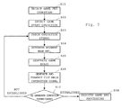
- FIG. 7 is a flowchart illustrating an outline of processing executed in the main game board 81.
- Step S11 when the money processing machine 60 receives the detection signal indicating insertion of a predetermined game fee (Step S11), the main game board 81 starts game processing (Steps S13 to S17), on receiving a game start operation with respect to the operation member 25b or 25c or the like (Step S12).
- the main game board 81 checks presence/absence of an operation signal from the steering rod 25a (Step S13), and according to the presence/absence and the content of the signal, determines the movement mode and the position of the moving object M in the virtual space (Step S14).
- the main game board 81 places the moving object M at the position determined in Step S14 in the virtual space in which various objects are arranged to construct a virtual model, and generates a game image as if the image is drawn from a virtual viewpoint located at the predetermined position (e.g., behind the moving object M) (Step S15). Further, the main game board 81 generates the tilt angle instruction signal based on the attitude, the movement mode and the like of the moving object M obtained in Step S14, and transmits the signal to the swing control board 84 (Step S16).
- Step S17 whether or not the predetermined gameover condition is established is detected.
- the game end processing is executed (Step S18), and in a case of being unestablished, the processing is returned to Step 13 in order to execute the game processing in the subsequent frame-time.
- FIGS. 8A to 8D are explanatory views illustrating the various swing modes of the swing member 20 while the game is in progress.
- FIG. 8A illustrates a swing mode in a case where a raising operation is performed with respect to the steering rod 25a.
- the operation rods 44 5 of the electric linear actuators 44a and 44b extend with an identical feeding amount to thereby drive upward the pads 23a and 23b being the driving points.
- the swing member 20 tilts in a direction in which a user O faces upward, and at the same time, a vertical position of the user O is heightened. Accordingly, due to the change of the posture and the height, the user O can sense a rising feeling extremely impressively. Further, as a video image showing that the moving object M is rising is displayed on the display device 26, the reality of the rising feeling of the user O can further be enhanced.
- FIG. 8B illustrates a swing mode in a case where a lowering operation is performed with respect to the steering rod 25a.
- the operation rods 44 5 of the electric linear actuators 44a and 44b contract with an identical feeding amount to thereby drive downward the pads 23a and 23b being the driving points.
- the swing member 20 tilts in a direction in which a user O faces downward, and at the same time, the vertical position of the user O is lowered. Accordingly, due to the change of the posture and the height, the user O can sense a lowering feeling extremely impressively. Further, as a video image showing that the moving object M is lowering is displayed on the display device 26, the reality of the lowering feeling of the user O can further be enhanced.
- FIGS. 8C and 8D illustrates a swing mode in a case where a right-turning operation or a left-turning operation is performed with respect to the steering rod 25a.
- each of the operation rods 44 5 of the electric linear actuators 44a and 44b extends or contracts in such a manner that the heights of the pads 23a and 23b are made different to each other.
- the swing member 20 is tilted right or left to make the user O sense a right-turning feeling or a left-turning feeling.
- the reality of the turning feeling of the user O can further be heightened.
- the swing member 20 tilts right or left (rolling) and at the same time tilts in the direction in which the user O faces upward (pitching). Accordingly, the user O can sense a combined feeling of a turning feeling and a rising feeling.
- the swing member 20 tilts right or left (rolling) and at the same time tilts in the direction in which the user O faces downward (pitching). Accordingly, the user O can sense a combined feeling of a turning feeling and a lowering feeling. As such, the tilt of the swing member 20 can be changed in the various modes.
- the left and right driving points 23a and 23b and the driving mechanisms 41a and 41b are provided to the front side of the ball portion 32b.
- the driving points 23a and 23b and the driving mechanisms 41a and 41b may be provided to the rear side of the ball portion 32b.
- the driving points 23a and 23b are driven downward, and when a lowering operation is performed with respect to the steering rod 25a, the driving points 23a and 23b are driven upward.
- a swing game machine operating in a similar manner to that of the above-mentioned embodiment of the present invention can be realized except that the driving direction of the driving points are different from that of the above-mentioned embodiment of the present invention.
- the degree of the change of the tilt angle of the swing member 20 by extending or contracting the operation rods 44 5 of the driving mechanisms 41a and 41b by the same amount, the distance that the user moves in vertical direction by the tilt of the pitching of the swing member 20 by the same angle, and the like can be adjusted.
- the electric linear actuators 44a and 44b are employed in the driving mechanisms.
- any arbitrary means can be used to vertically drive the driving points 23a and 23b.
- the driving points 23a and 23b can be driven in a similar manner to that of the above-mentioned embodiment of the present invention by employing another mechanism such as an oil hydraulic cylinder.
- the driving points 23a and 23b can be hung from an upper position of the game machine 1 and driven by towing or the like.
Landscapes
- Engineering & Computer Science (AREA)
- Theoretical Computer Science (AREA)
- Multimedia (AREA)
- Aviation & Aerospace Engineering (AREA)
- Business, Economics & Management (AREA)
- Physics & Mathematics (AREA)
- Educational Administration (AREA)
- Educational Technology (AREA)
- General Physics & Mathematics (AREA)
- User Interface Of Digital Computer (AREA)
- Processing Or Creating Images (AREA)
Abstract
Description
- The present invention relates to a swing device in which a swing member on which a user rides is allowed to swing to thereby make the user sense a rising or lowering feeling and the like, and a control method therefor. To be specific, the present invention relates to a swing device with which a user can body-sense a rising or lowering feeling that can be felt while a moving object such as an aircraft, a ship, a vehicle, or an animal is in a rising or lowering movement, and a control method therefor.
- Up to now, there is known a body-sensible swing game machine placed in an amusement facility such as a game arcade, in which a swing member on which a user rides is caused to swing according to an operation to an operation unit (see, for example,
Japanese Utility Model Application Laid-open No. Hei 3-107993 - In this game machine, in order to make the user body-sense a attitude or a movement mode in a virtual space of a virtual moving object (e.g., fighter aircraft) whose moving mode in the virtual space is determined based on an operation by the user, there is employed a structure in which the swing member on which a seat, a steering rod, and the like are mounted is supported by a fulcrum placed on the front side of the seat and two driving points on the rear side of the seat, and the driving points are moved vertically, to thereby change a tilt angle of the swing member with respect to a horizontal plain.
- That is, in a case where an operation is performed to raise the moving object, both of the driving points are moved downward to tilt the swing member in a direction in which the user faces upward, thereby the user can body-sense a rising feeling. In a case where an operation is performed to lower the moving object, both of the driving points are moved upward to tilt the swing member in a direction in which the user faces downward, thereby the user can body-sense a lowering feeling.
- Further, in recent years, in order to make a user body-sense a rising or lowering feeling more impressively or with higher reality, there is realized a game machine in which the number of driving points of a swing member is increased or the degree of freedom of driving directions of driving points is increased. However, increasing the number of the drive points or the degree of freedom of driving directions inevitably leads to a problem of increased size or cost of the machine.
- The present invention has been made to solve the above-mentioned problem and therefore it is an object of the present invention to provide a swing machine which is able to make a user body-sense a rising or lowering and/or turning feeling more impressively or with higher reality with a simple structure
- The present invention relates to a swing device including:
- a swing member on which a user rides;
- a fulcrum support mechanism for swingably supporting the swing member at a fulcrum; and
- a first driving mechanism for swingably supporting the swing member at a first driving point thereof and driving the first driving point in a vertical direction (upward/downward direction), the first driving point being spaced apart from the fulcrum in a longitudinal direction (front/rear direction) of the swing member,
- The inventors of the present invention have conducted extensive studies about the structures of the conventional game machines such as one disclosed in
Japanese Utility Model Application Laid-open No. Hei 3-107993 - Hereinafter, the mechanism of the present invention will be described in comparison with the conventional structure described in
Japanese Utility Model Application Laid-open No. Hei 3-107993 - As shown in the figures, in the
game machine 1, anoperation portion 3, adisplay device 4 and aseat 5 on which a user O can sit are mounted on aswing member 2 swingably supported at two support points P0 and P1. Based on an operation with respect to theoperation portion 3, a moving mode of a virtual moving object (e.g., fighter aircraft; hereinafter, sometimes simply referred to as moving object) in a virtual space is determined, and a video image of the moving object in the virtual space (or a video image of the virtual space drawn from a viewpoint of the moving object) is displayed on thedisplay device 4. - Note that in a case where a rotation of the
game machine 1 in a lateral direction (rotation about a line connecting the two support points P0 and P1) needs to be regulated or controlled, in addition to support mechanisms at the support points P0 and P1, it is necessary to provide auxiliary means such as guide means for maintaining the level of theswing member 2 in the lateral direction. - In the conventional structure, as shown in FIG. 2A, the support point P1 on a front side of a riding position of the user O serves as a fulcrum whose movement in a vertical direction is regulated, and the support point P0 on the rear side of the riding position of the user O serves as a driving point which is moved in the vertical direction.
- Accordingly, in a case where an operation to raise the moving object is performed with respect to the
operation portion 3, in order to make the user O sense a rising feeling, the driving point P0 is driven downward so as to tilt theswing member 2 in a direction in which the user faces upward as represented by a dotted line of FIG. 2A. In this case, the vertical position of the user O is lowered by an amount represented by reference symbol H. Thus, the user O senses a rising feeling because his/her body faces upward, and simultaneously senses a lowering feeling because his/her body is moved downward, which causes the result that the rising feeling, which is originally intended to be attained, is cancelled. - The similar situation also occurs in a case where an operation is performed so as to lower the moving object. In order to make the user O sense a lowering feeling, the driving point P0 is driven upward. Then, the
swing member 2 tilts in a direction in which the user O faces downward, and at the same time, the vertical position of the user is heightened. Thus, the user senses a rising feeling as well as a lowering feeling, which causes the result that the lowering feeling, which is originally intended to be attained, is cancelled. - In the present invention, the above-mentioned problems are solved by a constitution, as shown in FIG. 2B, that the support point P0 on the rear side of the riding position of the user O serves as the fulcrum whose movement in the vertical direction is regulated, and the support point P1 apart from the fulcrum P0 in a longitudinal direction (forward direction in the example shown in FIG. 2B) serves as a first driving point which is moved in the vertical direction.
- Accordingly, in a case where an operation to raise the moving object is performed with respect to the
operation portion 3, the first driving point P1 on the front side is driven upward so as to tilt theswing member 2 in the direction in which the user O faces upward as represented by a dotted line of FIG. 2B. In this case, the vertical position of the user O is heightened by an amount represented by reference symbol H. Thus, the user senses a rising feeling because his/her body faces upward, and simultaneously senses another rising feeling because his/her body is moved upward, thereby the synergistic effect of which significantly enhances impression or reality of the rising feeling. - The similar situation also occurs in a case where the operation to lower the moving object is performed. The driving point P1 on the front side is driven downward to tilt the
swing member 2 in the direction in which the user O faces downward. In this case, the vertical position of the user is lowered. Thus, the user senses a lowering feeling because his/her body faces downward, and simultaneously senses another lowering feeling because his/her body is moved downward, thereby a synergistic effect of which significantly enhances impression or reality of the lowering feeling. - The effects of the present invention is attained by changing the tilt angle of the
swing member 2 by rotating theswing member 2 about the fulcrum P0 placed at the rear side of the riding position of the user O and therefore, the vertical movement of the fulcrum P0 needs to be regulated to a certain extent. However, note that a structure can also be employed in which the fulcrum P0 moves vertically by an amount in a range sufficiently small with respect to the vertical movement of the first driving point P1. - Likewise, it is sufficient if the first driving point P1 in the swing device of the present invention is spaced apart from the fulcrum P0 by a predetermined amount in the longitudinal direction. Therefore, even in a case where the first driving point P1 is placed on the rear side of the fulcrum P0 as shown in FIG. 2C, the effects of the present invention can also be attained by the mechanism similar to that explained with respect to FIG. 2B. Note that from a viewpoint of a space efficiency or the like, it is preferable that the first driving point P1 be placed on the front side of the fulcrum P0, especially on the front side of the riding position of the user as shown in FIG. 2B.
- The swing device of the present invention can be used for the body-
sensible game machine 1 with which the user steers the virtual moving object while enjoying such a feeling that the user actually rides on the moving object. In addition, the swing device of the present invention can also be used for a body-sensible video image appreciation device with which a user watches a video image from a viewpoint of a moving object with enjoying such a feeling that the user actually rides on the moving object. As such, the swing device of the present invention can be applied to arbitrary device which is intended to make a user body-sense a rising feeling, a lowering feeling, or the like. - The swing member of the present invention is necessary to have a strength and a size allowing the user to ride on, and a shape thereof may be a plate-like shape as shown in FIGS 1A, 1B and 2A to 2C. Alternatively, the shape may be a three-dimensional shape such as a shape of a fighter aircraft or a shape of a cockpit thereof.
- The fulcrum support mechanism and the first driving mechanism of the present invention are necessary to be ones for swingably supporting the swing member. Examples of the support mechanism for swingably supporting the swing member include a universal joint and a ball joint.
- An arbitrary mechanism capable of driving the first driving point P1 in a vertical direction, such as an oil hydraulic cylinder, can be employed as the first driving mechanism of the present invention. A linear actuator excellent in a driving length, driving velocity, driving force, and so on, is particularly preferably employed.
- Note that, from a viewpoint of enhancing a transfer efficiency of the driving force, it is most preferable that, assuming a virtual sphere whose center corresponds to the fulcrum P0 and radius corresponds to a line segment connecting the fulcrum P0 and the first driving point P1, the driving force be applied in a tangential direction with respect to the sphere. However, in a case where a driving direction by the first driving mechanism is made always orthogonal to the line segment connecting the fulcrum P0 and the first driving point P1, the angle formed by a driving direction of the first driving mechanism and the above-mentioned line segment changes as the first driving point P1 moves on a surface of the sphere whose radius corresponds to the line segment. Therefore, a mechanism, such as a cylinder, which performs linear movement cannot constantly perform tangential movement to the sphere surface in reality.
- Accordingly, in the case where the first driving mechanism is one for performing the linear movement, it is preferable that an operational direction of a supporting force by the first driving mechanism is orthogonal to the line connecting the fulcrum P0 and the first driving point P1 in a reference state (e.g., a state of starting or finishing a game in the embodiment to be described later, or a state where the moving object is in level flight in the virtual space).
- In the present invention, the riding position refers to a position of the user on the swing member in the operational state, i.e. while the first driving point is driven by the first driving mechanism. For example, in the case of the structure in which the user sits on the seat on the swing member in the operational state, the riding position of the present invention corresponds to the position of the seat. Although, a case where the user sits on the seat is exemplified in this example, the seat is not always necessarily provided to realize the present application. For example, in a case where anti-drop means for preventing a user standing upright from dropping from the swing member is provided, the seat is not necessarily provided.
- In the specification of the present invention, the terms indicating the directions of forward, backward, left, and right are used based on which direction the user faces in the operational state, that is, while the first driving point is driven by the first driving mechanism. The forward direction refers to the direction that the user faces, the backward direction refers to a reverse direction thereof, and the left and right directions indicate the directions orthogonal to the front and rear directions in the horizontal plane.
- The present invention preferably relates to a swing device further including:
- a second driving mechanism for swingably supporting the swing member at a second driving point thereof and driving the second driving point in a vertical direction independently from the first driving mechanism, the second driving point being spaced apart from the fulcrum in a longitudinal direction of the swing member, and being spaced apart from the first driving point in a lateral direction of the swing member (second aspect).
- That is, in addition to the structure of the first aspect of the present invention, the second aspect of the present invention is characterized by including the second driving mechanism for driving the second driving point in the vertical direction, the second driving point spaced apart from the fulcrum in the longitudinal direction and spaced apart from the first drive means in the lateral direction.
- Accordingly, in the second aspect of the present invention, by raising or lowering the first and second driving points simultaneously, similarly to the first aspect of the present invention, it is possible to make the user body-sense a rising/lowering feeling. In addition, by vertically driving the first and second driving points in a manner that the their heights are different to each other, it is also possible to make the user body-sense a turning feeling to the left or right of the virtual moving object moving in the virtual space, or a combined feeling of a turning feeling to the left or right and a rising/lowering feeling thereof.
- In the present invention, it is preferable that the swing device further include:
- a support shaft projecting between the first driving point and the second driving point; and
- static determinate maintaining means having a guide hole defined therein through which the support shaft is rotatably inserted, for regulating movement of the support shaft in the lateral direction of the swing member, and guiding the support shaft in the vertical direction (third aspect).
- In the third aspect of the present invention, a line connecting the fulcrum and the support shaft serves as an axial center of the swing member and the degree of freedom of the movement of the swing member is limited to the raising and lowering movement of the axial center along the guide hole and the rotational movement of the swing member about the axial center. Thus, it becomes possible to readily maintain static determinate of the swing member. It is particularly preferable that the support shaft be positioned such that the distances therefrom to the first and second driving points are the same.
- In the present invention, it is preferable that the driving point is placed on a front side of the riding position of the user in the longitudinal direction of the swing member (fourth aspect).
- That is, assuming that driving mechanisms of identical performances are used, the larger the distance between the fulcrum position and the driving points are, the lower power (lower torque) the movement can be performed with. However, since the fulcrum is placed on the rear side of the seat of the user in the first and second aspects of the present invention, comparing the cases where the driving points are spaced apart from the fulcrum in one of the front direction and the rear direction, the entire device can be made compact in the case the driving points are placed on the front side of the seat of the user.
- In the present invention, it is preferable that the swing device further include:
- an operation member for transmitting an operation signal according to an operation by the user; and
- processing means for specifying a movement mode of a virtual moving object in a virtual space in response to the operation signal from the operation member, wherein:
- the first driving mechanism drives the first driving point according to the movement mode of the virtual moving object specified by the processing means (fifth aspect).
- In the fifth aspect of the present invention, the user can recognize the movement mode of the moving object determined by the processing means based on the operation that the user performs by himself/herself. Accordingly, it is possible to make the user body-sense a rising, lowering or turning feeling, or the like with higher reality by activating the first driving mechanism according to the movement mode of the moving object, e.g., in the case where the moving object rises, the first driving point is driven so as to raise the front portion of the swing member, and in the case where the moving object lowers, the first driving point is driven so as to lower the front portion of the swing member.
- In the present invention, it is preferable that the swing device further include:
- a display device placed on a front side of the riding position of the user in the longitudinal direction of the swing member, for displaying one of a video image of a virtual moving object moving in a virtual space and a video image of a virtual space drawn from a virtual viewpoint moving in the virtual space,
- the first driving mechanism drives the first driving point according to a movement mode of one of the virtual moving object and the virtual viewpoint (sixth aspect).
- In the sixth aspect of the present invention, the first driving mechanism is operated according to the movement mode of the moving object or the virtual viewpoint recognized by the user based on the video image displayed by the display device. Thus, it is possible to make the user body-sense a rising/lowering feeling or a turning feeling or the like with much higher reality.
- In the sixth aspect of the present invention, the video movie can be a video image of a real moving object moving in a real space, a video image of a landscape, an animation video image or a video image created using computer graphics. In a case with the former video images, the first driving mechanism can be operated according to the movement mode of the real or virtual moving object or the real or virtual viewpoint (video camera) recorded in the recording means in advance. In a case with the latter video image, the movement mode of the virtual moving object or the virtual viewpoint can be determined based on data used for creating the computer graphics, and the first driving mechanism can be operated according to the determined movement mode.
- The display device of the sixth aspect of the present invention may be mounted at a position in front of the riding position of the user on the swing member as shown in FIGS. 1A, 1B and 2A to 2C, or at a position in front of the swing member spaced apart therefrom. In the case where the display device is mounted on the swing member, a liquid crystal monitor, which is lighter in weight and has a higher resistance against vibration than other display devices such as a CRT, is preferably used.
- In the present invention, each of the first and second driving mechanism is preferably placed orthogonal to a line connecting the fulcrum and the first and second driving points, respectively, while the swing member is placed at a reference position (seventh aspect).
- That is, assuming spheres whose radii correspond to a line segments connecting the fulcrum and the first and second driving points, it is mechanically desirable that each of the first and second driving mechanisms be positioned in a tangential direction with respect to each of the spheres. However, in a case of actually positioning the first and second driving mechanism as described above, support stages of the first and second driving mechanisms are spaced apart from each other, with an disadvantageous result that a width of the entire game machine becomes larger. Thus, as described above, it is preferable that the first and second driving mechanisms of the present invention are positioned such that each the operational direction of the driving mechanisms is orthogonal to the line connecting the fulcrum P0 and the driving points P1 in a reference state of the swing member (e.g., a state where the swing member is placed at a standard position). As a result, the driving efficiency of the driving mechanisms can be enhanced in the expanding and contracting directions, and at the same time the width of the entire device can be designed compact.
- The present invention relates to a control method for a swing device, the swing device comprising:
- a swing member on which a user rides;
- an operation member for transmitting an operation signal in response to an operation by the user;
- processing means for specifying a movement mode of a virtual moving object in a virtual space in response to the operation signal from the operation member;
- a fulcrum support mechanism for supporting the swing member at the fulcrum, the fulcrum being placed on a rear side of a riding position of the user of the swing member in the longitudinal direction of the swing member; and
- a first driving mechanism for swingably supporting the swing member at a first driving point thereof and driving the first driving point in a vertical direction, the first driving point being spaced apart from the fulcrum in a longitudinal direction of the swing member,
- operating the first driving mechanism so that a front portion of the swing member rises, in a case where the movement mode of the virtual moving object specified by the processing means indicates rising in the virtual space; and
- operating the first driving mechanism so that the front portion of the swing member lowers, in a case where the movement mode of the virtual moving object specified by the processing means indicates lowering in the virtual space (eighth aspect).
- In the eighth aspect of the present invention, the user can recognize the movement mode of the moving object determined by the processing means based on the operation that the user performs by himself/herself. Accordingly, the effect similar to that of the fifth aspect of the present invention can be attained.
- The present invention relates to a control method for a swing device,
the swing device comprising: - a swing member on which a user rides;
- a display device placed on a front side of a riding position of the user in the longitudinal direction of the swing member, for displaying one of a video image of a virtual moving object moving in a virtual space and a video image drawn from a virtual viewpoint moving in the virtual space;
- a fulcrum support mechanism for supporting the swing member at a fulcrum, the fulcrum being placed on a rear side of the riding position of the user of the swing member in the longitudinal direction of the swing member; and
- a first driving mechanism for swingably supporting the swing member at a first driving point thereof and moving the first driving point in a vertical direction, the first driving point being spaced apart from the fulcrum in a longitudinal direction of the swing member,
- operating the first driving mechanism so that a front portion of the swing member rises, in a case where one of the virtual moving object and the virtual viewpoint rises in the virtual space; and
- operating the first driving mechanism so that the front portion of the swing member lowers, in a case where one of the virtual moving object and the virtual viewpoint lowers in the virtual space (ninth aspect).
- In the ninth aspect of the present invention, the user can recognize the movement mode of the moving object or the virtual viewpoint based on the video image displayed on the display device. Accordingly, the effect similar to that of the sixth aspect of the present invention can be attained.
- Note that, the eighth and ninth aspects of the present invention may include additional structures like in the second to seventh aspects of the present invention, in which a swing member further including a second driving mechanism for driving a second driving point spaced apart from a fulcrum in the longitudinal direction and spaced apart from the first driving point in the lateral direction is used, or the first and second driving mechanisms are operated so that a front portion of the swing member rises or lowers according to the rising or the lowering of the virtual moving object or the virtual viewpoint.
- In the accompanying drawings:
- FIG. 1A is an explanatory view illustrating a structure of an exemplified swing game machine;
- FIG. 1B is an explanatory view illustrating the structure of the exemplified swing game machine;
- FIG. 2A is an explanatory view illustrating a driving manner of a swing member of a swing game machine of a conventional structure;
- FIG. 2B is an explanatory view illustrating a driving manner of a swing member of a swing game machine of a structure of the present invention;
- FIG. 2C is an explanatory view illustrating a driving manner of the swing member of a swing game machine of the structure of the present invention;
- FIG. 3 is a perspective view illustrating an outer structure of a swing game machine according to an embodiment of the present invention;
- FIG. 4A is a perspective view illustrating a structure of the swing game machine according to the embodiment of the present invention;
- FIG. 4B is a side view illustrating the structure of the swing game machine according to the embodiment of the present invention;
- FIG. 4C is a front view illustrating the structure of the swing game machine according to the embodiment of the present invention;
- FIG. 4D is a rear view illustrating the structure of the swing game machine according to the embodiment of the present invention;
- FIG. 5A is an explanatory view illustrating a structure of a fulcrum support mechanism;
- FIG. 5B is an explanatory view illustrating a structure of a universal joint;
- FIG. 5C is an explanatory view illustrating a structure of an electric linear actuator;
- FIG. 6 is a block diagram illustrating a control unit of the swing game machine according to the embodiment of the present invention;
- FIG. 7 is a flowchart illustrating contents of processing executed in the swing game machine according to the embodiment of the present invention;
- FIG. 8A is an explanatory view illustrating a tilt mode of a swing member in a case where a moving object is raised;
- FIG. 8B is an explanatory view illustrating a tilt mode of the swing member in a case where the moving object is lowered;
- FIG. 8C is an explanatory view illustrating a tilt mode of the swing member in a case where the moving object is turned right; and
- FIG. 8D is an explanatory view illustrating a tilt mode of the swing member in a case where the moving object is turned left.
- Hereinafter, an embodiment of the present invention will be explained referring to a body-sensible
swing game machine 1 as an example in which a movement mode of a virtual moving object M (e.g., fighter aircraft) in a virtual space is determined based on an operation with respect to an operation member and the determined movement mode is displayed on a display device. - FIG. 3 is a perspective view illustrating an outer structure of the
swing game machine 1 to which a swing device of the present invention is applied, and FIGS. 4A to 4D are perspective, side, front, and rear views, respectively, illustrating theswing game machine 1 from which a casing frame is removed. - As shown in the figures, the
swing game machine 1 mainly includes abase stage 10, aswing member 20, afulcrum support mechanism 30, a drivingmechanism storing unit 40, and amoney processing machine 60. - Of those, the
base stage 10 serves as a seating to which thefulcrum support mechanism 30, a first driving mechanism 41a, asecond driving mechanism 41b, a static determinate maintainingmechanism 50, and so on to be described later are provided. In an inner space of thebase stage 10, acontrol unit 80 for controlling an operation of thegame machine 1, various connection cables, and the like can be stored. - Note that the
base stage 10 is unnecessary in a case where thefulcrum support mechanism 30, the first driving mechanism 41a, thesecond driving mechanism 41b, the static determinate maintainingmechanism 50, and the like are directly installed on a floor surface of a facility in which thegame machine 1 is installed. - The
swing member 20 includes afloor member 21 extending in a longitudinal direction, a mountingstage 22 provided to a front portion of thefloor member 21, a reinforcingframe 23, and so on. On thefloor member 21, aseat 24 having a shape similar to a cockpit of a fighter aircraft is provided. To the mountingstage 22, anoperation panel 25 for receiving from a user various game operations is provided and adisplay device 26 supported by the reinforcingframe 23 are provided. - The
operation panel 25 includes asteering rod 25a being an operation member with which the user instructs a movement direction and the like of the moving object M. By operating thesteering rod 25a in forward and backward directions, the moving object M can be raised and lowered, and by operating thesteering rod 25a in left and right directions, the moving object M can be turned left and right. Theoperation panel 25 further includesoperation members auxiliary operation member 25d is arranged at a side of theseat 24. - The
display device 26 displays a video image showing a movement mode of the moving object M in the virtual space, which is operated by the user. The video image can be an arbitrary video image with which the user can recognize the movement mode of the moving object M. Examples thereof includes a video image of the moving object M observed from a viewpoint fixed in the virtual space, and a video image of the moving object M observed from a viewpoint inside or behind the moving object M, which is movable in the virtual space together with the moving object M while maintaining a predetermined positional relation therewith. - As the
display device 26, a liquid crystal monitor, which is highly resistant to vibration compared to other display devices such as a CRT, is preferably used. As the liquid crystal monitor is light in weight, thedisplay device 26 having a large screen size as shown in the figures can be used. Therefore, a game image with a visual impact can be displayed. - The
swing member 20 is supported by a mechanism to be described later in such a manner that theswing member 20 is spaced apart from thebase stage 10 by a predetermined distance so as to enable theswing member 20 to perform movements including rolling and pitching. - The
fulcrum support mechanism 30 is arranged at a position spaced apart from theseat 24 being a riding position of the user of theswing member 20 by a predetermined distance therebehind. - FIG. 5A is an enlarged sectional view illustrating the
fulcrum support mechanism 30. - As shown in the figure, the
fulcrum support mechanism 30 includes: asupport column 31 having a square pole shape and projecting upright on thebase stage 10; a boll joint 32 fixed to an upper end of thesupport column 31; afixation block 33 provided to thefloor member 21 so as to cover anopening 21a defined in thefloor member 21, and having a square-C-shaped space for storing the ball joint 32 therein; and acover 34 for covering an upper portion of thefixation block 33. - The ball joint 32 includes: a
shaft bearing member 32a having a sphere-shaped space defined therein; aball portion 32b rotatably received and held in the sphere-shaped space; and aball shaft 32c having an end to which theball portion 32b is attached. The other end of theball shaft 32c is inserted and fixed to aninsertion hole 33a defined in a ceiling of thefixation block 33 with a nut or the like. - Accordingly, the
swing member 20 is swingably supported on thesupport column 31 so that theball portion 32b of the ball joint 32 serves as an unmovable fulcrum. - In the driving
mechanism storing unit 40 located in a front portion of thegame machine 1, the first driving mechanism 41a, thesecond driving mechanism 41b, and the static determinate maintainingmechanism 50 are stored. - The first and
second driving mechanism base stage 10;universal joints linear actuators universal joints universal joints linear actuators universal joints swing member 20 atpads frame 23, which is mounted to the mountingstage 22. - Note that the distance from the
pad 23a to theball portion 32b of the ball joint 32 being the fulcrum of theswing member 20 is the same as the distance from thepad 23b to theball portion 32b. Further, the support stages 42a and 42b are provided so that the axial directions of the electriclinear actuators ball portion 32b being the fulcrum of theswing member 20 and thepads - Herein, the
universal joints - As shown in the figure, each of the
universal joints cross shaft 43x having twoshaft members lower plate 43y having on an upper surface thereof a pair ofshaft bearing portions 43y1 for rotatably supporting both ends of oneshaft member 43 x1; and anupper plate 43z having on a lower surface thereof a pair ofshaft bearing portions 43z1 for rotatably supporting both ends of theother shaft member 43 x2. Thus, a member provided to an upper surface of theupper plate 43z is swingably supported with respect to a member provided to a lower surface of thelower plate 43y. - FIG. 5C is an explanatory view illustrating a structure of the electric
linear actuators - As shown in the figure, each of the electric
linear actuators casing 441; aservo motor 442; aboll screw shaft 443 rotationally driven by theservo motor 442; aball circulation nut 444 screwed by theboll screw shaft 443 and prohibited to rotate together with theboll screw shaft 443; and anoperation rod 445 integrally fixed to theball circulation nut 444. Theball circulation nut 444 converts a rotational movement of theboll screw shaft 443 by theservo motor 442 into a liner movement, thereby driving theoperation rod 445 forward and backward in the shaft direction thereof. - Accordingly, the
swing member 20 is swingably supported by theuniversal joints pads operation rod 445 of the electriclinear actuators - The static determinate maintaining
mechanism 50 includes: asupport shaft 51 projectingly provided to the reinforcingframe 23 at a midst position between thepads swing member 20; asupport stage 52 provided on a front portion of an upper surface of thebase stage 10 and aguide frame 53 provided on the upper surface of thesupport stage 52 with a predetermined slant angle and having aguide hole 53a, in which thesupport shaft 51 is rotatably inserted, for guiding thesupport shaft 51 only in the vertical direction. - Herein, the
support shaft 51 is provided in such a manner that an axial center thereof directs theball portion 32b being the fulcrum of theswing member 20. Thesupport shaft 51 is guided by theguide hole 53a, whereby the degree of freedom of the movement of theswing member 20 is limited to the vertical movement along theguide hole 53a of the support shaft 51 (pitching), and the rotational movement of theswing member 20 about the support shaft 51 (rolling). Thus, static determinate of theswing member 20 is prevented from being lost while theswing member 20 is driven by the electriclinear actuators - The
money processing machine 60 includes: acoin insertion opening 61 defined in an outer surface of the casing, for receiving a game fee; and acoin processing unit 62 provided inside the casing, for detecting an inserted coin and transmitting a coin detection signal to thecontrol unit 80. - FIG. 6 is a block diagram illustrating a configuration of the
control unit 80 of theswing game machine 1. - As shown in the figure, the
control unit 80 includes amain game board 81, an interface I/O board (JVS I/O BD) 82, a solid state relay (SSR) control board (relay BD) 83, a swing control board (MOTION PC) 84, a leftdrive control circuit 85, a rightdrive control circuit 86, animage processing circuit 87, and an audiosound processing circuit 88. - Herein, the
main game board 81 includes a CPU, ROM, RAM, and the like and integrally controls the operation of thegame machine 1. To be specific, the CPU expands a game program and a system program stored in the ROM in advance on the RAM, performs computing according to an operation signal input from thevarious operation members 25a to 25d via the interface I/O board 82 to compute movement mode and the position of the moving object M in the virtual space momentarily, and transmits a tilt angle instruction signal for instructing a pitching angle and a rolling angle of theswing member 20 to theswing control board 84 based on a result of the computation. Further, themain game board 81 generates a drawing command and an audio sound command as tasks for drawing a performance image and outputting a performance audio sound, and transmits the commands to theimage processing circuit 87 and the audiosound processing circuit 88, respectively. - The solid state
relay control board 83 generates a safety signal for instructing to suspend the movement of the electriclinear actuators detection sensor 28 provided in the vicinity of thegame machine 1, and transmits the signal to theswing control board 84. Examples of thedetection sensor 28 includes a mechanical sensor for detecting a seatbelt wearing state at theseat 24 and an optical sensor for detecting that a person is approaching a dangerous portion of thegame machine 1. - The
swing control board 84 includes a CPU, ROM, RAM, and the like for processing the driving of theswing member 20, and controls the driving of the electriclinear actuators main game board 81 and the solid staterelay control board 83. - To be specific, the
swing control board 84 determines a rotational direction and a rotational rate of theservo motor 442 in the electriclinear actuators main game board 81, and transmits a driving signal for instructing the rotational direction and the rotational rate to the left and rightdrive control circuits drive control circuits - The left and right
drive control circuits servo motors 442 in the electriclinear actuators O board 82, thereby controlling the pitching and the rolling of theswing member 20. - The
image processing circuit 87 performs a drawing processing of the game image in response to the drawing command from themain game board 81, which is displayed on thedisplay device 26. The audiosound processing circuit 88 causes, for example, left andright speakers seat 24 to output a game audio sound synthesized based on the audio sound command from themain game board 81. - FIG. 7 is a flowchart illustrating an outline of processing executed in the
main game board 81. - As shown in the figure, when the
money processing machine 60 receives the detection signal indicating insertion of a predetermined game fee (Step S11), themain game board 81 starts game processing (Steps S13 to S17), on receiving a game start operation with respect to theoperation member - In the game processing, the following processing is executed in every frame-times.
- That is, the
main game board 81 checks presence/absence of an operation signal from thesteering rod 25a (Step S13), and according to the presence/absence and the content of the signal, determines the movement mode and the position of the moving object M in the virtual space (Step S14). - Next, the
main game board 81 places the moving object M at the position determined in Step S14 in the virtual space in which various objects are arranged to construct a virtual model, and generates a game image as if the image is drawn from a virtual viewpoint located at the predetermined position (e.g., behind the moving object M) (Step S15). Further, themain game board 81 generates the tilt angle instruction signal based on the attitude, the movement mode and the like of the moving object M obtained in Step S14, and transmits the signal to the swing control board 84 (Step S16). - Then, in Step S17, whether or not the predetermined gameover condition is established is detected. In a case of being established, the game end processing is executed (Step S18), and in a case of being unestablished, the processing is returned to
Step 13 in order to execute the game processing in the subsequent frame-time. - FIGS. 8A to 8D are explanatory views illustrating the various swing modes of the
swing member 20 while the game is in progress. - FIG. 8A illustrates a swing mode in a case where a raising operation is performed with respect to the
steering rod 25a. In this case, theoperation rods 445 of the electriclinear actuators pads swing member 20 tilts in a direction in which a user O faces upward, and at the same time, a vertical position of the user O is heightened. Accordingly, due to the change of the posture and the height, the user O can sense a rising feeling extremely impressively. Further, as a video image showing that the moving object M is rising is displayed on thedisplay device 26, the reality of the rising feeling of the user O can further be enhanced. - FIG. 8B illustrates a swing mode in a case where a lowering operation is performed with respect to the
steering rod 25a. In this case, theoperation rods 445 of the electriclinear actuators pads swing member 20 tilts in a direction in which a user O faces downward, and at the same time, the vertical position of the user O is lowered. Accordingly, due to the change of the posture and the height, the user O can sense a lowering feeling extremely impressively. Further, as a video image showing that the moving object M is lowering is displayed on thedisplay device 26, the reality of the lowering feeling of the user O can further be enhanced. - Each of FIGS. 8C and 8D illustrates a swing mode in a case where a right-turning operation or a left-turning operation is performed with respect to the
steering rod 25a. In these cases, each of theoperation rods 445 of the electriclinear actuators pads swing member 20 is tilted right or left to make the user O sense a right-turning feeling or a left-turning feeling. Further, at the same time, as a video image showing that the moving object M is turning right or left is displayed on thedisplay device 26, the reality of the turning feeling of the user O can further be heightened. - Note that, in a case where the
operation rod 445 of one of the electriclinear actuators operation rod 445 of the other of the electriclinear actuators swing member 20 tilts right or left (rolling) and at the same time tilts in the direction in which the user O faces upward (pitching). Accordingly, the user O can sense a combined feeling of a turning feeling and a rising feeling. Likewise, in a case where theoperation rod 445 of one of the electriclinear actuators operation rod 445 of the other of the electriclinear actuators swing member 20 tilts right or left (rolling) and at the same time tilts in the direction in which the user O faces downward (pitching). Accordingly, the user O can sense a combined feeling of a turning feeling and a lowering feeling. As such, the tilt of theswing member 20 can be changed in the various modes. - The present invention has been explained by way of the exemplified embodiment. However, the present invention is not limited to the above-mentioned embodiment of the present invention, and various modifications and alterations can be made within the scope of the claims.
- For example, in the above-mentioned embodiment of the present invention, description has been made by way of an example in which the left and right driving points 23a and 23b and the driving
mechanisms 41a and 41b are provided to the front side of theball portion 32b. However, the drivingpoints mechanisms 41a and 41b may be provided to the rear side of theball portion 32b. In this case, for example, when a raising operation is performed with respect to thesteering rod 25a, the drivingpoints steering rod 25a, the drivingpoints - Further, in the above-mentioned embodiment of the present invention, by adjusting the distance between the
seat 24 being the riding position of the user and theball portion 32b, the distances between theball portion 32b and the drivingpoints points swing member 20 by extending or contracting theoperation rods 445 of the drivingmechanisms 41a and 41b by the same amount, the distance that the user moves in vertical direction by the tilt of the pitching of theswing member 20 by the same angle, and the like can be adjusted. - Further, in the above-mentioned embodiment of the present invention, description has been made by way of an example in which the electric
linear actuators points points points game machine 1 and driven by towing or the like. - In addition, the shape, the dimension, and the like of the respective members constituting the swing game machine of the above-mentioned embodiment of the present invention are merely described as examples. Any alternative shape and dimension can be employed to implement the present invention.
Claims (9)
- A swing device (1), characterized in that the swing device (1) comprises:a swing member (2) on which a user (O) rides;a fulcrum support mechanism (30) for swingably supporting the swing member (2) at a fulcrum (32b); anda first driving mechanism (41a) for swingably supporting the swing member (2) at a first driving point (23a) thereof and driving the first driving point (23a) in a vertical direction, the first driving point (23a) being spaced apart from the fulcrum (32b) in a longitudinal direction of the swing member (20),and in that the fulcrum (32b) is placed on a rear side of a riding position (24) of the user (O) in the longitudinal direction of the swing member (20).
- A swing device (1) according to claim 1, characterized in that the swing device (1) further comprises:a second driving mechanism (41b) for swingably supporting the swing member (2) at a second driving point (23b) thereof and driving the second driving point (23b) in a vertical direction independently from the first driving mechanism (41a), the second driving point (23b) being spaced apart from the fulcrum (32b) in a longitudinal direction of the swing member (20), and being spaced apart from the first driving point (23a) in a lateral direction of the swing member.
- A swing device (1) according to claim 2, characterized in that the swing device (1) further comprises:a support shaft (51) projecting between the first driving point (23a) and the second driving point (23b); andstatic determinate maintaining means (53) having a guide hole (53a) defined therein through which the support shaft (51) is rotatably inserted, for regulating movement of the support shaft (51) in the lateral direction of the swing member (20), and guiding the support shaft (51) in the vertical direction.
- A swing device (1) according to any one of claim 1 to 3, characterized in that the first driving point (23a) is placed on a front side of the riding position (24) of the user (0) in the longitudinal direction of the swing member (20).
- A swing device according to any one of claims 1 to 4, characterized in that the swing device (1) further comprises:an operation member (25) for transmitting an operation signal according to an operation by the user (O); andprocessing means (80) for specifying a movement mode of a virtual moving object (M) in a virtual space in response to the operation signal from the operation member (25), and in that:the first driving mechanism (41a) drives the first driving point (23a) according to the movement mode of the virtual moving object (M) specified by the processing means (80).
- A swing device according to any one of claims 1 to 5, characterized in that the swing device (1) further comprises: a display device (26) placed on a front side of the riding position (24) of the user (O) in the longitudinal direction of the swing member (20), for displaying one of a video image of a virtual moving object (M) moving in a virtual space and a video image of a virtual space drawn from a virtual viewpoint moving in the virtual space, and in that:the first driving mechanism (41a) drives the first driving point (23a) according to a movement mode of one of the virtual moving object (M) and the virtual viewpoint.
- A swing device according to any one of claims 1 to 6, characterized in that the first driving mechanism (41a) is placed orthogonal to a line connecting the fulcrum (32b) and the first driving point (23a) while the swing member (20) is placed at a reference position.
- A control method for a swing device (1), characterized in that:the swing device comprises:a swing member (29) on which a user (O) rides;an operation member (25) for transmitting an operation signal in response to an operation by the user (O);processing means (80) for specifying a movement mode of a virtual moving object (M) in a virtual space in response to the operation signal from the operation member (25);a fulcrum support mechanism (30) for supporting the swing member (20) at the fulcrum (32b), the fulcrum (32b) being placed on a rear side of a riding position (24) of the user (O) of the swing member (20) in the longitudinal direction of the swing member (20); anda first driving mechanism (41a) for swingably supporting the swing member (20) at a first driving point (23a) thereof and driving the first driving point (23a) in a vertical direction, the first driving point (23a) being spaced apart from the fulcrum (32b) in a longitudinal direction of the swing member(20),the control method comprises:operating the first driving mechanism (41a) so that a front portion of the swing member (20) rises, in a case where the movement mode of the virtual moving object (M) specified by the processing means (80) indicates rising in the virtual space; andoperating the first driving mechanism (41a) so that the front portion of the swing member (20) lowers, in a case where the movement mode of the virtual moving object (M) specified by the processing means (80) indicates lowering in the virtual space.
- A control method for a swing device (1), characterized in that:the swing device (1) comprises:a swing member (20) on which a user (O) rides;a display device (26) placed on a front side of a riding position (24) of the user (O) in the longitudinal direction of the swing member (20), for displaying one of a video image of a virtual moving object (M) moving in a virtual space and a video image drawn from a virtual viewpoint moving in the virtual space;a fulcrum support mechanism (30) for supporting the swing member (20) at a fulcrum (32b), the fulcrum (32b) being placed on a rear side of the riding position (24) of the user (O) of the swing member (20) in the longitudinal direction of the swing member(20); anda first driving mechanism (41a) for swingably supporting the swing member (20) at a first driving point (23a) thereof and driving the first driving point (23a) in a vertical direction, the first driving point (23a) being spaced apart from the fulcrum (32b) in a longitudinal direction of the swing member(20),the control method comprises:operating the first driving mechanism (41a) so that a front portion of the swing member (20) rises, in a case where one of the virtual moving object (M) and the virtual viewpoint rises in the virtual space; andoperating the first driving mechanism (41a) so that the front portion of the swing member (20) lowers, in a case where one of the virtual moving object (M) and the virtual viewpoint lowers in the virtual space.
Applications Claiming Priority (1)
| Application Number | Priority Date | Filing Date | Title |
|---|---|---|---|
| JP2006213982A JP2008036099A (en) | 2006-08-04 | 2006-08-04 | Oscillator and control method of the oscillator |
Publications (2)
| Publication Number | Publication Date |
|---|---|
| EP1884269A2 true EP1884269A2 (en) | 2008-02-06 |
| EP1884269A3 EP1884269A3 (en) | 2010-03-10 |
Family
ID=38799307
Family Applications (1)
| Application Number | Title | Priority Date | Filing Date |
|---|---|---|---|
| EP07014103A Withdrawn EP1884269A3 (en) | 2006-08-04 | 2007-07-18 | Swing device and control method for a swing device |
Country Status (5)
| Country | Link |
|---|---|
| US (1) | US20080039216A1 (en) |
| EP (1) | EP1884269A3 (en) |
| JP (1) | JP2008036099A (en) |
| CN (1) | CN101125259A (en) |
| TW (1) | TW200808420A (en) |
Cited By (3)
| Publication number | Priority date | Publication date | Assignee | Title |
|---|---|---|---|---|
| ITMO20090176A1 (en) * | 2009-07-07 | 2011-01-08 | Penta Automazioni Di Molinaro Raffa Ele | LUDIC DEVICE WITH A PERFECT COIN. |
| WO2011064560A1 (en) * | 2009-11-25 | 2011-06-03 | Next Step Solutions Ltd | Motion simulator |
| DE102020121559A1 (en) | 2020-08-17 | 2022-02-17 | RACEREBEL GmbH | Formula racing car modular model, driving simulator with the model |
Families Citing this family (15)
| Publication number | Priority date | Publication date | Assignee | Title |
|---|---|---|---|---|
| US8663019B2 (en) * | 2009-11-12 | 2014-03-04 | Wms Gaming Inc. | Gaming machine chair and wagering game systems and machines with a gaming chair |
| US8678936B2 (en) * | 2009-11-12 | 2014-03-25 | Wms Gaming Inc. | Gaming machine chair and wagering game systems and machines with a gaming chair |
| US20130130798A1 (en) * | 2010-07-12 | 2013-05-23 | Amit NIR | Video game controller |
| EP2707863B1 (en) * | 2011-05-11 | 2018-08-01 | Oceaneering International, Inc. | Trackless dark ride vehicle, system, and method |
| AT511523B1 (en) * | 2011-05-23 | 2013-06-15 | Amst Systemtechnik Gmbh | DEVICE FOR SPATIAL MOVEMENT OF PERSONS |
| KR101377594B1 (en) * | 2013-02-20 | 2014-03-25 | 주식회사 모션디바이스 | Motion simulator |
| KR101459908B1 (en) * | 2013-05-20 | 2014-11-07 | 현대자동차주식회사 | Apparatus and method for safe drive inducing game |
| US9814991B2 (en) * | 2014-10-07 | 2017-11-14 | Universal City Studios Llc | Actuatable motion base system |
| AT516901B1 (en) * | 2015-03-06 | 2018-07-15 | Amst Systemtechnik Gmbh | Flight simulator and flight simulation method |
| CN106237620B (en) * | 2016-08-04 | 2017-12-29 | 新昌县回山新农村建设有限公司 | A kind of municipal administration entertainment and sports device |
| JP2019129450A (en) * | 2018-01-25 | 2019-08-01 | 三菱プレシジョン株式会社 | Multi-display system and simulator |
| CN108648560B (en) * | 2018-06-21 | 2023-05-05 | 北京瀚科科技集团有限公司 | Flight Control Simulator with Adaptive Adjustment of Stroke, Rod Force and Control Mode |
| TWI682747B (en) * | 2018-12-24 | 2020-01-21 | 宏碁股份有限公司 | Swing chair |
| IT202000003101A1 (en) * | 2020-02-17 | 2021-08-17 | Marty & Nelly S R L | Driving simulator support |
| CN119673021B (en) * | 2024-12-19 | 2025-11-11 | 南京航空航天大学 | Flight simulation teaching equipment |
Family Cites Families (20)
| Publication number | Priority date | Publication date | Assignee | Title |
|---|---|---|---|---|
| US2924028A (en) * | 1960-02-09 | geisse | ||
| GB875799A (en) * | 1956-09-21 | 1961-08-23 | Gen Precision Inc | Improvements in or relating to grounded aircraft-training apparatus |
| JP2560930Y2 (en) * | 1990-02-22 | 1998-01-26 | 株式会社セガ・エンタープライゼス | Rocking amusement machine |
| JP2607971B2 (en) * | 1990-07-02 | 1997-05-07 | 株式会社セガ・エンタープライゼス | Rotating somersault device |
| JPH0751109Y2 (en) * | 1991-04-30 | 1995-11-22 | 株式会社セガ・エンタープライゼス | Rocking play machine |
| US5605462A (en) * | 1991-07-12 | 1997-02-25 | Denne Developments Ltd. | Motion imparting apparatus |
| JP3476874B2 (en) * | 1993-10-19 | 2003-12-10 | カヤバ工業株式会社 | Simulated experience device |
| JP2801882B2 (en) * | 1996-02-20 | 1998-09-21 | コナミ株式会社 | Vehicle gaming machine |
| JP2828956B2 (en) * | 1996-08-06 | 1998-11-25 | コナミ株式会社 | Simulator seat support |
| JP2945884B2 (en) * | 1997-06-13 | 1999-09-06 | コナミ株式会社 | Experience drive device |
| JPH11146981A (en) * | 1997-11-18 | 1999-06-02 | Sony Corp | Rocking device |
| US6162058A (en) * | 1998-02-03 | 2000-12-19 | Kumyang Co., Ltd. | Motion base device for simulators |
| JP4349537B2 (en) * | 1998-06-26 | 2009-10-21 | 株式会社バンダイナムコゲームス | Simulator |
| JP3553432B2 (en) * | 1999-09-24 | 2004-08-11 | 本田技研工業株式会社 | Riding simulation device |
| JP4119064B2 (en) * | 1999-11-24 | 2008-07-16 | 本田技研工業株式会社 | Road simulation equipment |
| GB0016059D0 (en) * | 2000-06-30 | 2000-08-23 | Denne Phillip R M | Improvements in motion simulators |
| JP4344080B2 (en) * | 2000-10-16 | 2009-10-14 | 日本ビーテーエー株式会社 | Flight simulator equipment |
| US6733293B2 (en) * | 2001-01-26 | 2004-05-11 | Provision Entertainment, Inc. | Personal simulator |
| EP1449185B1 (en) * | 2001-11-29 | 2017-09-06 | Simuline, Inc. | Motion simulator |
| US7195486B2 (en) * | 2002-08-06 | 2007-03-27 | Mcgraw Robert W | Reconfigurable simulation structure |
-
2006
- 2006-08-04 JP JP2006213982A patent/JP2008036099A/en active Pending
-
2007
- 2007-07-12 TW TW096125369A patent/TW200808420A/en unknown
- 2007-07-16 US US11/778,577 patent/US20080039216A1/en not_active Abandoned
- 2007-07-18 EP EP07014103A patent/EP1884269A3/en not_active Withdrawn
- 2007-08-03 CN CNA2007101431777A patent/CN101125259A/en active Pending
Cited By (4)
| Publication number | Priority date | Publication date | Assignee | Title |
|---|---|---|---|---|
| ITMO20090176A1 (en) * | 2009-07-07 | 2011-01-08 | Penta Automazioni Di Molinaro Raffa Ele | LUDIC DEVICE WITH A PERFECT COIN. |
| WO2011064560A1 (en) * | 2009-11-25 | 2011-06-03 | Next Step Solutions Ltd | Motion simulator |
| DE102020121559A1 (en) | 2020-08-17 | 2022-02-17 | RACEREBEL GmbH | Formula racing car modular model, driving simulator with the model |
| WO2022037976A1 (en) | 2020-08-17 | 2022-02-24 | RACEREBEL GmbH | Modular model of a formula racing car, driving simulator having the model |
Also Published As
| Publication number | Publication date |
|---|---|
| JP2008036099A (en) | 2008-02-21 |
| EP1884269A3 (en) | 2010-03-10 |
| US20080039216A1 (en) | 2008-02-14 |
| TW200808420A (en) | 2008-02-16 |
| CN101125259A (en) | 2008-02-20 |
Similar Documents
| Publication | Publication Date | Title |
|---|---|---|
| US20080039216A1 (en) | Swing device and control method for a swing device | |
| KR101941465B1 (en) | Virtual Reality Simulation System | |
| CN103718226B (en) | Devices for human movement in space | |
| JP3170638B2 (en) | Virtual reality experience device | |
| CN101842822B (en) | Sports Platform Video Games Racing and Flight Simulators | |
| CA2262211C (en) | Tiltable platform | |
| JP2020517374A (en) | Seated motion simulation type amusement park attraction | |
| JPH1118025A (en) | Image presentation device | |
| KR102276788B1 (en) | virtual reality exercise device | |
| WO2005050985A1 (en) | Image display device and simulation apparatus | |
| EP3563915B1 (en) | Motion simulating device | |
| US12272006B2 (en) | Rotational navigation in a virtual environment with a visual reference | |
| KR20230066091A (en) | Systems and methods for facilitating guest control of ride vehicles | |
| JP4413203B2 (en) | Image presentation device | |
| KR101364594B1 (en) | Tangible Snowboard Apparatus based on Bi-directional Interaction between motion of user and Motion Platform | |
| JP3331378B2 (en) | Control stick with kickback mechanism and game device | |
| JP4344080B2 (en) | Flight simulator equipment | |
| US20190321735A1 (en) | Trackless amusement ride | |
| KR102758620B1 (en) | Simulator apparatus and method for freely experiencing virtual reality training contents | |
| EP3804826A1 (en) | Virtual simulation device | |
| KR102328405B1 (en) | 4d vr simulation system with increased flying feel | |
| JP2589581Y2 (en) | Simulated control device | |
| JPH1021425A (en) | Image processing device, image processing method, game device, and game device | |
| KR101750064B1 (en) | Apparatus and method for simulatin virtual experience | |
| KR101873232B1 (en) | Riding Simulator |
Legal Events
| Date | Code | Title | Description |
|---|---|---|---|
| PUAI | Public reference made under article 153(3) epc to a published international application that has entered the european phase |
Free format text: ORIGINAL CODE: 0009012 |
|
| AK | Designated contracting states |
Kind code of ref document: A2 Designated state(s): AT BE BG CH CY CZ DE DK EE ES FI FR GB GR HU IE IS IT LI LT LU LV MC MT NL PL PT RO SE SI SK TR |
|
| AX | Request for extension of the european patent |
Extension state: AL BA HR MK YU |
|
| PUAL | Search report despatched |
Free format text: ORIGINAL CODE: 0009013 |
|
| AK | Designated contracting states |
Kind code of ref document: A3 Designated state(s): AT BE BG CH CY CZ DE DK EE ES FI FR GB GR HU IE IS IT LI LT LU LV MC MT NL PL PT RO SE SI SK TR |
|
| AX | Request for extension of the european patent |
Extension state: AL BA HR MK RS |
|
| RIC1 | Information provided on ipc code assigned before grant |
Ipc: G09B 9/14 20060101ALI20100203BHEP Ipc: A63G 31/16 20060101ALI20100203BHEP Ipc: A63F 13/08 20060101AFI20071217BHEP |
|
| 17P | Request for examination filed |
Effective date: 20100908 |
|
| AKX | Designation fees paid |
Designated state(s): DE FR GB |
|
| 17Q | First examination report despatched |
Effective date: 20120307 |
|
| STAA | Information on the status of an ep patent application or granted ep patent |
Free format text: STATUS: THE APPLICATION IS DEEMED TO BE WITHDRAWN |
|
| 18D | Application deemed to be withdrawn |
Effective date: 20120201 |