EP1883340B1 - Phantomgerät - Google Patents
Phantomgerät Download PDFInfo
- Publication number
- EP1883340B1 EP1883340B1 EP06747547A EP06747547A EP1883340B1 EP 1883340 B1 EP1883340 B1 EP 1883340B1 EP 06747547 A EP06747547 A EP 06747547A EP 06747547 A EP06747547 A EP 06747547A EP 1883340 B1 EP1883340 B1 EP 1883340B1
- Authority
- EP
- European Patent Office
- Prior art keywords
- phantom
- imaging
- imaging device
- mimicking
- segments
- Prior art date
- Legal status (The legal status is an assumption and is not a legal conclusion. Google has not performed a legal analysis and makes no representation as to the accuracy of the status listed.)
- Expired - Lifetime
Links
Images




Classifications
-
- G—PHYSICS
- G09—EDUCATION; CRYPTOGRAPHY; DISPLAY; ADVERTISING; SEALS
- G09B—EDUCATIONAL OR DEMONSTRATION APPLIANCES; APPLIANCES FOR TEACHING, OR COMMUNICATING WITH, THE BLIND, DEAF OR MUTE; MODELS; PLANETARIA; GLOBES; MAPS; DIAGRAMS
- G09B23/00—Models for scientific, medical, or mathematical purposes, e.g. full-sized devices for demonstration purposes
- G09B23/28—Models for scientific, medical, or mathematical purposes, e.g. full-sized devices for demonstration purposes for medicine
- G09B23/30—Anatomical models
-
- A—HUMAN NECESSITIES
- A61—MEDICAL OR VETERINARY SCIENCE; HYGIENE
- A61B—DIAGNOSIS; SURGERY; IDENTIFICATION
- A61B5/00—Measuring for diagnostic purposes; Identification of persons
- A61B5/0059—Measuring for diagnostic purposes; Identification of persons using light, e.g. diagnosis by transillumination, diascopy, fluorescence
-
- A—HUMAN NECESSITIES
- A61—MEDICAL OR VETERINARY SCIENCE; HYGIENE
- A61B—DIAGNOSIS; SURGERY; IDENTIFICATION
- A61B8/00—Diagnosis using ultrasonic, sonic or infrasonic waves
- A61B8/58—Testing, adjusting or calibrating the diagnostic device
- A61B8/587—Calibration phantoms
-
- A—HUMAN NECESSITIES
- A61—MEDICAL OR VETERINARY SCIENCE; HYGIENE
- A61B—DIAGNOSIS; SURGERY; IDENTIFICATION
- A61B2560/00—Constructional details of operational features of apparatus; Accessories for medical measuring apparatus
- A61B2560/02—Operational features
- A61B2560/0223—Operational features of calibration, e.g. protocols for calibrating sensors
- A61B2560/0228—Operational features of calibration, e.g. protocols for calibrating sensors using calibration standards
- A61B2560/0233—Optical standards
-
- A—HUMAN NECESSITIES
- A61—MEDICAL OR VETERINARY SCIENCE; HYGIENE
- A61B—DIAGNOSIS; SURGERY; IDENTIFICATION
- A61B5/00—Measuring for diagnostic purposes; Identification of persons
- A61B5/145—Measuring characteristics of blood in vivo, e.g. gas concentration or pH-value ; Measuring characteristics of body fluids or tissues, e.g. interstitial fluid or cerebral tissue
- A61B5/1455—Measuring characteristics of blood in vivo, e.g. gas concentration or pH-value ; Measuring characteristics of body fluids or tissues, e.g. interstitial fluid or cerebral tissue using optical sensors, e.g. spectral photometrical oximeters
-
- A—HUMAN NECESSITIES
- A61—MEDICAL OR VETERINARY SCIENCE; HYGIENE
- A61B—DIAGNOSIS; SURGERY; IDENTIFICATION
- A61B8/00—Diagnosis using ultrasonic, sonic or infrasonic waves
Definitions
- the invention relates to a phantom device for mimicking anatomical structures.
- Imaging techniques like photography and filming using visible, infrared or ultraviolet optical radiation are generally known in the art and commonly used to image, measure and characterize the surfaces of tissue.
- Optical imaging techniques have also been described to detect and display anatomical structures buried beneath the surface of biological tissue.
- the invention has as one of it's objections to provide a phantom device for mimicking anatomical structures, wherein the imaging performance of an imaging apparatus can be tested and calibrated using predetermined dynamical behavior.
- the invention provides a phantom device according to the features of claim 1.
- the phantom device comprises at least one electronic device layer comprising segmented areas of liquid crystals for forming a graphic layout of an anatomical structure; the segments comprising dyes of various absorbing characteristics for mimicking anatomical structures such as blood vessels; the areas further comprising electrically controllable optical diffuser and/or absorber elements for varying the absorption in the segments so as to mimic dynamical properties of said anatomical structure.
- the various dyes in the segmented areas mimic multiple DC components corresponding to different stages of for instance oxygenation in blood vessels
- the dynamic variation of the absorption may be realized by the scattering crystals, which cause the light to diffuse and vary the translucence of the device.
- the phantom device further comprises a tissue layer covering said at least one electronic device, for mimicking tissue covering said anatomical structure.
- tissue layer covering said at least one electronic device, for mimicking tissue covering said anatomical structure.
- multiple electronic device layers are embedded in tissue layers to mimic the 3D properties of an organic object such as an arm or the like.
- the phantom device provides a series of predetermined static and dynamical test parameters which can be measured by an imaging device.
- the phantom device comprises an output unit for outputting signals representative for a predetermined dynamical behavior of said phantom device, for calibrating an imaging device for imaging buried structures.
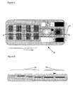
- Figure 1 shows a first embodiment of a phantom device according to the invention
- Figure 2 shows a cross section of the phantom device according to Figure 1 ;
- Figure 4 shows a second embodiment of a phantom device according to the invention.
- Figure 5 shows a cross section of the phantom device according to Figure 4 along line A-A;
- Figure 6 shows another embodiment of the phantom according to the invention.
- Figure 7 shows a system of a phantom device according to the invention and an imaging device to be calibrated
- Figure 8 shows another imaging device to be calibrated by a phantom device according to the invention.
- a phantom device 1 having a dyed structure 2 embedded on a substrate 3 to represent realistically a structure of blood vessels in an object such as a human arm.
- the dyed structure is preferably covered with a material 4 rendering similar absorption, reflection, scattering and transmission properties similar to normal biological tissue.
- different regions having different optical properties may be present, for example, to represent a fat layer, bones etc.
- the dyed structure 2 is provided on a substrate, preferably, a polymer substrate 3 which houses segmented areas that are doted with dyes of various absorbing characteristics for mimicking anatomical structures such as blood vessels to be imaged by a imaging device 5. Furthermore, in the areas electrically controllable optical diffuser and/or absorber elements are provided for varying the absorption in the segments so as to mimic dynamical properties of said anatomical structure.
- the dyed areas are provided with boundaries that are formed by conductive zones for forming an electrodes. In this way, the diffuser/absorber elements can be electrically controlled to vary the diffusing/scattering properties of the elements.
- the path length of optical radiation used for imaging purposes is varied, resulting in a variation in scattering and/or absorption or other optical characteristics of the dyed area.
- dynamic characteristics of blood vessels can be imitated to mimic the pulsating properties of the vessels.
- absorption characteristics can be exactly predetermined, so that a variety of degrees of oxygenation of blood the vessels can mimicked.
- venous and arterial blood vessels can be mimicked, wherein, as is illustrated in Figure 2 the arterial blood vessels may be formed by the deepest electronic device 6 and the venous blood vessels may be formed by the more superficially arranged electronic device 3. Between the devices 3, 6 a tissue layer 7 is provided.
- vessel patterns 2 can be formed by traces filled with a suitable dye mixture. In case of liquid dyes these may be mixed with a liquid crystal fluid. The scattering and absorption properties of the LCDs assigned to different areas can be electrically modulated in a reproducible manner.
- the top layer is a diffuse layer having optical properties of a tissue surface, for example, skin, bladder wall, stomach wall, etc.
- natural chromophores e.g. melanine
- artificial dyes may be incorporated to imitate e.g. skin color.
- Figure 3 schematically shows a preferred embodiment where the device 1 is deformable and comprises an actuator 8 for deforming said device 1 into predetermined forms.
- the device 1 is deformable and comprises an actuator 8 for deforming said device 1 into predetermined forms.
- Such an embodiment allows to create dynamic convex or concave distortion of the tissue phantom 1.
- defined dynamic behavior of curved surfaces is very important to test the dynamic behavior of the equipment to be tested/calibrated (e.g. alternating reflections on such surfaces can lead to temporal detector saturation).
- Figure 4 shows an alternative embodiment of a phantom device 9 according to the invention.
- the segmented areas comprise test patterns 10, 11 for testing a resolving power of a imaging device for imaging buried structures.
- the test patterns 10 as will be apparent from the cross sectional view of Figure 5 may be provided on different depths of the phantom device 9.
- a pattern may be provided, so that the tissue layer is increasing in thickness. With such a test pattern, a maximum penetration depth can be determined for the imaging apparatus.
- test patterns e.g. parallel line pairs 10 and/or fanned beams 11 at various pitches and with various spectral behavior
- Electrically controllable LCD-devices can be combined with these test patterns in order to add physiological signals (e.g. respiration and heartbeat).
- physiological signals e.g. respiration and heartbeat
- a spectrally neutral gray scale and a reference color pattern incl. IR
- the test patterns 10, 11 may have well known 3-dimensional shapes and patterns (e.g. slits, trenches, cylinders, etc.).
- the external and internal surfaces of the device 9 can have an irregular shape that closely matches a part of the body.
- the phantom can be used as a reference or training tool in combination with devices that enable the imaging of buried structures like blood vessels.
- a region of a soft material, suitable for puncturing e.g. with a needle
- an underlying target e.g. a vessel pattern. This would allow users to practice their surgical, injection or blood withdrawal skills. It would also be a well defined and repeatable method to compare the functional parameters of different devices for imaging beneath the tissue surface.
- Figure 6 shows that the phantom 1 can be equipped with a central processing unit 12, one or more optical detectors 13, connections offering physiological reference signals 14 and a means of communication 15 with the device 16 to be calibrated or tested.
- a central processing unit 12 one or more optical detectors 13, connections offering physiological reference signals 14 and a means of communication 15 with the device 16 to be calibrated or tested.
- Some devices that optically extract physiological parameters from tissue are designed to make use of an accepted clinical parameter by methods generally known in the art.
- FIG. 7 of Electro Cardio Grams (ECG), a photoplethysmographic trace as derived from a traditional pulse oximeter, a respiration signal from a ventilator or patient monitor, dynamic blood pressure, and the like.
- ECG Electro Cardio Grams
- Figure 7A shows an example of reflectance mode photoplethysmographic signals derived from a camera (lower two traces). The upper three traces are reference signals obtained using clinical devices (HP-patient monitor and Nellcor pulse oximeter).
- Figure 7B shows Fourier spectra of two reference traces (respiration and pulse oximeter plethysmographic output) compared to a camera-derived signal.
- the device already needs to generate signals like these in order to modulate the LCD-devices, which also allows to make these signals externally available using standard connections as accepted by the field. By not only presenting these signals but also their setting values (e.g. using a digital communication protocol) an automatic calibration can be performed.
- the phantom can provide comparison between a stored waveform or image and the actually obtained waveform or image.
- Automatic recognition of devices that are compatible (and of those that are non-compatible) with the phantom can be achieved by the aforementioned communication bus and/or by comparing signals received by optical detectors in the phantom with reference parameters (i.e. if via a communication bus the device would present itself as a model X but send out a different characteristic wavelength or modulation, then compatibility is not warranted and e.g. an error message could be displayed.
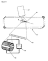
- Figure 8 shows another imaging device to be calibrated.
- the imaging device is an ultrasound imaging device 17 since it has been found that the electronically orientable crystals 18 of the liquid crystal device 19 are also effective in varying the acoustic properties of the phantom device.
- the scattering behaviour of liquid crystal materials when electrically controlled by a controller 20, the scattering behaviour of liquid crystal materials also varies for ultrasonic waves and it is thus possible to construct a 3-dimensional array of individually controllable ultrasound scattering volume elements.
- liquid crystal devices such as PDLCs are very stable and behave like solid state components. Their reproduceability is excellent and individually controllable segments can be integrated into complex detailed 3-dimensional structures ("holographic structure simulators").
- 3D-structures 21 (as seen in Figure 8 , mimicking a 3D blood vessel or also as shaped as described previously in this patent application in the section about optical behaviour) with variable known scattering properties can be used as a calibration tool for general echoscopic imaging devices.
- the contrast level for discerning contrast between various structures can be determined. This contrast level is an indicator of echoscopic imaging quality.
- the PDLC technique is also highly applicable for the calibration of harmonic ultrasound imaging devices (which use non-linear scattering behaviour to form an image).
- a typical application would e.g. be a bladderscan calibration phantom with stepwise variable scattering levels of the liquid volume within the simulated bladder.
- PDLC technology can also be used to calibrate doppler ultrasound devices. By sequentially varying the scatter behaviour of a large amount of PDLC elements placed in a line, the propagation of a pulsating bloodflow can be imitated. Since the pitch of segments and timing of segment excitation can be controlled very accurately, a well determined time/speed profile can be generated for the simulated pulsating flow.
Landscapes
- Health & Medical Sciences (AREA)
- Life Sciences & Earth Sciences (AREA)
- Engineering & Computer Science (AREA)
- Physics & Mathematics (AREA)
- General Health & Medical Sciences (AREA)
- Medical Informatics (AREA)
- Pathology (AREA)
- Biomedical Technology (AREA)
- Heart & Thoracic Surgery (AREA)
- Molecular Biology (AREA)
- Surgery (AREA)
- Animal Behavior & Ethology (AREA)
- Biophysics (AREA)
- Public Health (AREA)
- Veterinary Medicine (AREA)
- General Physics & Mathematics (AREA)
- Radiology & Medical Imaging (AREA)
- Pure & Applied Mathematics (AREA)
- Medicinal Chemistry (AREA)
- Algebra (AREA)
- Computational Mathematics (AREA)
- Nuclear Medicine, Radiotherapy & Molecular Imaging (AREA)
- Mathematical Analysis (AREA)
- Mathematical Optimization (AREA)
- Mathematical Physics (AREA)
- Chemical & Material Sciences (AREA)
- Business, Economics & Management (AREA)
- Educational Administration (AREA)
- Educational Technology (AREA)
- Theoretical Computer Science (AREA)
- Ultra Sonic Daignosis Equipment (AREA)
- Measurement Of The Respiration, Hearing Ability, Form, And Blood Characteristics Of Living Organisms (AREA)
- Instructional Devices (AREA)
- Magnetic Resonance Imaging Apparatus (AREA)
- Input Circuits Of Receivers And Coupling Of Receivers And Audio Equipment (AREA)
Claims (14)
- Phantomgerät (1) zum Nachahmen anatomischer Strukturen mit:Wenigstens einer Lage elektronischer Komponenten (36) mit segmentierten Gebieten (2) zur Bildung der Umrisse einer anatomischen Struktur, wobei die Segmente (2) Farbstoffe mit verschiedenen Absorptionscharakteristiken aufweisen, um anatomische Strukturen, wie etwa Blutgefäße, nachzuahmen, wobei die Gebiete (2) weiter orientierbare Diffusor- und/oder Absorptionselemente zum Variieren der optischen Absorption und/oder der Ultraschallabsorption in den Segmenten (2) aufweisen, um so die dynamischen Merkmale der anatomischen Struktur nachzuahmen.
- Phantomgerät nach Anspruch 1, das weiter eine Gewebelage (4, 7) aufweist, die die wenigstens eine elektronische Komponente (3, 6) bedeckt, um die anatomische Struktur überdeckendes Gewebe nachzuahmen.
- Phantomgerät nach Anspruch 1 oder 2, das weiter mehrfache Lagen elektronischer Komponenten (3, 6) aufweist, die in Gewebelagen (4, 7) eingebettet sind.
- Phantomgerät nach Anspruch 2, wobei die Gewebelage (4, 7) in der Dicke zunimmt.
- Phantomgerät nach einem der vorhergehenden Ansprüche, wobei die segmentierten Gebiete (3, 6) Testmuster (10, 11) aufweisen, um das Auflösungsvermögen eines abbildenden Gerätes zum Abbilden verdeckter Strukturen zu testen.
- Phantomgerät nach einem der vorhergehenden Ansprüche, wobei das Gerät verformbar ist und ein Stellglied (8) aufweist, um das Gerät in vorgegebene Formen zu verformen.
- Phantomgerät nach einem der vorhergehenden Ansprüche, wobei die Lage elektronischer Komponenten (3, 6) eine Polymerdispersion-Flüssigkristallanzeigeneinrichtung ist.
- Phantomgerät nach einem der vorhergehenden Ansprüche, das weiter eine Ausgabeeinheit (12, 15) zur Ausgabe von Signalen aufweist, die repräsentativ sind für ein vorgegebenes dynamisches Verhalten des Phantomgerätes, um ein abbildendes Gerät (16) zum Abbilden verdeckter Strukturen zu kalibrieren.
- System mit einem abbildenden Gerät (16) zum Abbilden verdeckter Strukturen und einem Phantomgerät (1) nach Anspruch 8, wobei das abbildende Gerät (16) einen Eingang zum Aufnehmen der Ausgabesignale und einer Einheit zur Einstellung der Kalibration des abbildenden Gerätes auf Grundlage der Ausgabesignale aufweist.
- System nach Anspruch 9, wobei das abbildende Gerät (16) eine Infrarotkamera ist.
- System nach Anspruch 9, wobei das abbildende Gerät (16) ein Ultraschallbildgerät ist.
- System nach Anspruch 11, wobei das Ultraschallbildgerät ein Abbildungsgerät mit harmonischer Ultraschalltechnik oder ein Doppler-Ultraschallgerät ist.
- Verfahren zum Kalibrieren eines Ultraschallabbildungsgerätes, wobei bei dem Verfahren: Wenigstens eine Lage elektronischer Komponenten (3, 6) mit orientierbaren Diffusor- und/oder Absorberelementen verwendet wird, um die Ultraschallabsorption in den Segmenten zu variieren, um so die dynamischen Eigenschaften einer anatomischen Struktur nachzuahmen.
- Verfahren nach Anspruch 13, bei dem weiter eine absorbierende Eigenschaft von benachbarten Flüssigkristallelementen sequentiell variiert wird, die in einer ein Blutgefäß nachahmenden 2D- oder 3D-Region (2) gebildet sind, um einen Blutfluss in der Region nachzuahmen.
Priority Applications (1)
| Application Number | Priority Date | Filing Date | Title |
|---|---|---|---|
| EP06747547A EP1883340B1 (de) | 2005-05-27 | 2006-05-17 | Phantomgerät |
Applications Claiming Priority (3)
| Application Number | Priority Date | Filing Date | Title |
|---|---|---|---|
| EP05076253A EP1726256A1 (de) | 2005-05-27 | 2005-05-27 | Phantomvorrichtung |
| EP06747547A EP1883340B1 (de) | 2005-05-27 | 2006-05-17 | Phantomgerät |
| PCT/NL2006/000252 WO2006126871A1 (en) | 2005-05-27 | 2006-05-17 | Phantom device |
Publications (2)
| Publication Number | Publication Date |
|---|---|
| EP1883340A1 EP1883340A1 (de) | 2008-02-06 |
| EP1883340B1 true EP1883340B1 (de) | 2010-03-31 |
Family
ID=34938311
Family Applications (2)
| Application Number | Title | Priority Date | Filing Date |
|---|---|---|---|
| EP05076253A Withdrawn EP1726256A1 (de) | 2005-05-27 | 2005-05-27 | Phantomvorrichtung |
| EP06747547A Expired - Lifetime EP1883340B1 (de) | 2005-05-27 | 2006-05-17 | Phantomgerät |
Family Applications Before (1)
| Application Number | Title | Priority Date | Filing Date |
|---|---|---|---|
| EP05076253A Withdrawn EP1726256A1 (de) | 2005-05-27 | 2005-05-27 | Phantomvorrichtung |
Country Status (7)
| Country | Link |
|---|---|
| US (1) | US7748252B2 (de) |
| EP (2) | EP1726256A1 (de) |
| JP (1) | JP4833283B2 (de) |
| AT (1) | ATE462351T1 (de) |
| DE (1) | DE602006013301D1 (de) |
| ES (1) | ES2343747T3 (de) |
| WO (1) | WO2006126871A1 (de) |
Families Citing this family (19)
| Publication number | Priority date | Publication date | Assignee | Title |
|---|---|---|---|---|
| WO2006135850A2 (en) * | 2005-06-10 | 2006-12-21 | Barbour Randall L | Electronically modulated dynamic optical phantoms for biomedical imaging |
| US8888498B2 (en) * | 2009-06-02 | 2014-11-18 | National Research Council Of Canada | Multilayered tissue phantoms, fabrication methods, and use |
| WO2011112559A2 (en) | 2010-03-08 | 2011-09-15 | Bruce Adams | System, method and article for normalization and enhancement of tissue images |
| US8687178B2 (en) * | 2010-09-30 | 2014-04-01 | Wavelight Gmbh | Process for testing a laser device |
| US9643029B2 (en) | 2013-09-26 | 2017-05-09 | Varian Medical Systems International Ag | Dosimetric end-to-end verification devices, systems, and methods |
| US9468403B2 (en) * | 2014-01-15 | 2016-10-18 | Hong Kong Applied Science and Technology Research Institute Company Limited | Single-body unit for pulse oximeter calibration |
| US9737284B2 (en) * | 2014-10-23 | 2017-08-22 | Korea Research Institute Of Standards And Science | Phantom for measuring thickness of thin layer using ultrasonic imaging device and method of using thereof |
| CN107735019B (zh) | 2015-06-30 | 2021-03-05 | 皇家飞利浦有限公司 | 利用多个ppg传感器的传感器系统和方法 |
| RU2018138979A (ru) | 2016-04-06 | 2020-05-12 | Конинклейке Филипс Н.В. | Способ, устройство и система для обеспечения возможности анализа свойства детектора показателя жизненно важной функции |
| WO2017191670A1 (ja) * | 2016-05-02 | 2017-11-09 | オリンパス株式会社 | 撮像用ファントムおよび光学撮像装置の評価方法 |
| KR101907672B1 (ko) * | 2017-01-31 | 2018-10-12 | 연세대학교 산학협력단 | 치과용 도플러 초음파 기기용 혈류 팬텀 및 이를 포함하는 팬텀 시스템 |
| US10993704B2 (en) | 2017-09-25 | 2021-05-04 | Verathon Inc. | System and method for calibration of mechanical three-dimensional ultrasound probe |
| CN109512460B (zh) * | 2018-12-30 | 2022-03-08 | 深圳北芯生命科技股份有限公司 | 血管内介入式超声成像测试用的体模 |
| EP3757974A1 (de) | 2019-06-28 | 2020-12-30 | Stichting IMEC Nederland | Simulatorvorrichtung |
| US11457846B2 (en) | 2019-10-31 | 2022-10-04 | Belun Technology (Ip) Company Limited | Tester for an optical measuring device |
| CN113514826B (zh) * | 2021-04-23 | 2024-06-28 | 浙江杜比医疗科技有限公司 | 一种用于dot成像系统的光学吸收动态模拟系统 |
| CN113729669A (zh) * | 2021-10-14 | 2021-12-03 | 湖南可孚芯驰医疗科技有限公司 | 一种ppg脉搏波模拟仪 |
| CN113786172B (zh) * | 2021-11-17 | 2022-02-22 | 深圳市脉度科技有限公司 | 生理参数测量系统及方法 |
| GB2629653A (en) | 2023-05-05 | 2024-11-06 | Biopixs Ltd | Functional phantom system |
Family Cites Families (11)
| Publication number | Priority date | Publication date | Assignee | Title |
|---|---|---|---|---|
| US4894013A (en) * | 1988-10-13 | 1990-01-16 | The United States Of America As Represented By The Department Of Health And Human Services | Anthropomorphic cardiac ultrasound phantom |
| US5416575A (en) * | 1991-11-18 | 1995-05-16 | Schwartz; Mark | Method and system for calibrating an optical density measurement apparatus |
| JPH09262234A (ja) * | 1996-03-28 | 1997-10-07 | Toshiba Corp | 超音波診断装置の検査方法並びにそれに使用するファントム |
| US6400973B1 (en) * | 1998-01-20 | 2002-06-04 | Bowden's Automated Products, Inc. | Arterial blood flow simulator |
| WO2002001280A2 (en) * | 2000-06-23 | 2002-01-03 | The University Of Akron | Electrically tunable microlens array containing liquid crystals |
| JP4681110B2 (ja) * | 2000-11-13 | 2011-05-11 | アロカ株式会社 | 超音波生体組織評価システム |
| AU2003230799A1 (en) * | 2002-04-05 | 2003-10-27 | Massachusetts Institute Of Technology | Systems and methods for spectroscopy of biological tissue |
| AU2004291062A1 (en) * | 2003-11-10 | 2005-06-02 | Angiotech International Ag | Medical implants and anti-scarring agents |
| JP2006010320A (ja) * | 2004-06-22 | 2006-01-12 | Tama Tlo Kk | 温度分布の観測方法、観測装置、及び、観測対象物 |
| JP2006116085A (ja) * | 2004-10-21 | 2006-05-11 | Matsushita Electric Ind Co Ltd | 超音波診断装置用ファントム |
| JP2006166956A (ja) * | 2004-12-13 | 2006-06-29 | Matsushita Electric Ind Co Ltd | 超音波診断装置用ファントム |
-
2005
- 2005-05-27 EP EP05076253A patent/EP1726256A1/de not_active Withdrawn
-
2006
- 2006-05-17 DE DE602006013301T patent/DE602006013301D1/de not_active Expired - Lifetime
- 2006-05-17 EP EP06747547A patent/EP1883340B1/de not_active Expired - Lifetime
- 2006-05-17 ES ES06747547T patent/ES2343747T3/es not_active Expired - Lifetime
- 2006-05-17 JP JP2008513389A patent/JP4833283B2/ja not_active Expired - Fee Related
- 2006-05-17 WO PCT/NL2006/000252 patent/WO2006126871A1/en not_active Ceased
- 2006-05-17 AT AT06747547T patent/ATE462351T1/de active
- 2006-05-17 US US11/915,548 patent/US7748252B2/en not_active Expired - Fee Related
Also Published As
| Publication number | Publication date |
|---|---|
| ES2343747T3 (es) | 2010-08-09 |
| ATE462351T1 (de) | 2010-04-15 |
| EP1726256A1 (de) | 2006-11-29 |
| JP4833283B2 (ja) | 2011-12-07 |
| DE602006013301D1 (de) | 2010-05-12 |
| US20080214936A1 (en) | 2008-09-04 |
| US7748252B2 (en) | 2010-07-06 |
| JP2008541829A (ja) | 2008-11-27 |
| WO2006126871A1 (en) | 2006-11-30 |
| EP1883340A1 (de) | 2008-02-06 |
Similar Documents
| Publication | Publication Date | Title |
|---|---|---|
| US7748252B2 (en) | Phantom device | |
| US7845949B2 (en) | Ultrasound training mannequin | |
| CN103426351B (zh) | 可远程复现的心动脉应脉诊训练装置及方法 | |
| Lai et al. | Design of anthropomorphic flow phantoms based on rapid prototyping of compliant vessel geometries | |
| US7583367B2 (en) | Catheter surgery simulation | |
| US20120191001A1 (en) | Combination non-invasive and invasive bioparameter measuring device | |
| EP0063649A1 (de) | Messeinrichtung zur nichtinvasiven Feststellung venöser bzw. arterieller Abfluss- und Durchflussstörungen | |
| US20200405169A1 (en) | Simulator device | |
| Rodriguez et al. | Tissue mimicking materials and finger phantom design for pulse oximetry | |
| CN111956235B (zh) | 一种反射式血氧探头或测量装置的标定方法 | |
| Nomoni et al. | A pulsatile optical tissue phantom for the investigation of light-tissue interaction in reflectance photoplethysmography | |
| Osorio-Sanchez et al. | Evaluation of skin pigmentation effect on photoplethysmography signals using a vascular finger phantom with tunable optical and mechanical properties | |
| Ma et al. | Light-guided dynamic phantom to mimic microvasculature for biomedical applications: an exploration for pulse oximeter | |
| US7576853B2 (en) | Electronically modulated dynamic optical phantoms for biomedical imaging | |
| KR101844001B1 (ko) | 인체 조직 모사 박막 광 팬텀 및 그 제조방법 | |
| Wieringa et al. | In vitro demonstration of an SpO2-camera | |
| Barbour et al. | Validation of near infrared spectroscopic (NIRS) imaging using programmable phantoms | |
| RU2777514C1 (ru) | Устройство для метрологического контроля состояния приборов оптической флоуметрии | |
| KR102782046B1 (ko) | 혈관 B-mode 초음파 영상 시험을 위한 모사 혈관 팬텀 시뮬레이터 | |
| Nomoni | Novel Pulsatile Phantoms in Photoplethysmography | |
| Christie | Study of Test Phantoms for Medical Photoacoustic and Optical Imaging Applications | |
| Jung et al. | Reduction of animal testing-Influence of the orientation of constructed blood vessels during the 3D printing on the measurement of the pseudo-oxygen saturation of an artificial blood substitute using conventional oxygen sensors: a test series | |
| CN121838589A (zh) | 仿体设备、测试系统及测试方法 | |
| Rathod et al. | Fabrication of SLA-printed pulsatile phantoms with epidermal melanin layers for wearable photoplethysmography device testing with U-shaped vasculature microchannels | |
| KR20080012444A (ko) | 인체 조직 모방 광 팬텀 및 그 제작방법 |
Legal Events
| Date | Code | Title | Description |
|---|---|---|---|
| PUAI | Public reference made under article 153(3) epc to a published international application that has entered the european phase |
Free format text: ORIGINAL CODE: 0009012 |
|
| 17P | Request for examination filed |
Effective date: 20071207 |
|
| AK | Designated contracting states |
Kind code of ref document: A1 Designated state(s): AT BE BG CH CY CZ DE DK EE ES FI FR GB GR HU IE IS IT LI LT LU LV MC NL PL PT RO SE SI SK TR |
|
| DAX | Request for extension of the european patent (deleted) | ||
| GRAP | Despatch of communication of intention to grant a patent |
Free format text: ORIGINAL CODE: EPIDOSNIGR1 |
|
| GRAS | Grant fee paid |
Free format text: ORIGINAL CODE: EPIDOSNIGR3 |
|
| GRAA | (expected) grant |
Free format text: ORIGINAL CODE: 0009210 |
|
| AK | Designated contracting states |
Kind code of ref document: B1 Designated state(s): AT BE BG CH CY CZ DE DK EE ES FI FR GB GR HU IE IS IT LI LT LU LV MC NL PL PT RO SE SI SK TR |
|
| REG | Reference to a national code |
Ref country code: GB Ref legal event code: FG4D Ref country code: CH Ref legal event code: EP |
|
| REG | Reference to a national code |
Ref country code: IE Ref legal event code: FG4D |
|
| REF | Corresponds to: |
Ref document number: 602006013301 Country of ref document: DE Date of ref document: 20100512 Kind code of ref document: P |
|
| REG | Reference to a national code |
Ref country code: NL Ref legal event code: T3 |
|
| REG | Reference to a national code |
Ref country code: SE Ref legal event code: TRGR |
|
| REG | Reference to a national code |
Ref country code: CH Ref legal event code: NV Representative=s name: PATENTANWAELTE SCHAAD, BALASS, MENZL & PARTNER AG |
|
| PG25 | Lapsed in a contracting state [announced via postgrant information from national office to epo] |
Ref country code: LT Free format text: LAPSE BECAUSE OF FAILURE TO SUBMIT A TRANSLATION OF THE DESCRIPTION OR TO PAY THE FEE WITHIN THE PRESCRIBED TIME-LIMIT Effective date: 20100331 |
|
| REG | Reference to a national code |
Ref country code: ES Ref legal event code: FG2A Ref document number: 2343747 Country of ref document: ES Kind code of ref document: T3 |
|
| LTIE | Lt: invalidation of european patent or patent extension |
Effective date: 20100331 |
|
| PG25 | Lapsed in a contracting state [announced via postgrant information from national office to epo] |
Ref country code: SI Free format text: LAPSE BECAUSE OF FAILURE TO SUBMIT A TRANSLATION OF THE DESCRIPTION OR TO PAY THE FEE WITHIN THE PRESCRIBED TIME-LIMIT Effective date: 20100331 Ref country code: PL Free format text: LAPSE BECAUSE OF FAILURE TO SUBMIT A TRANSLATION OF THE DESCRIPTION OR TO PAY THE FEE WITHIN THE PRESCRIBED TIME-LIMIT Effective date: 20100331 Ref country code: LV Free format text: LAPSE BECAUSE OF FAILURE TO SUBMIT A TRANSLATION OF THE DESCRIPTION OR TO PAY THE FEE WITHIN THE PRESCRIBED TIME-LIMIT Effective date: 20100331 |
|
| PG25 | Lapsed in a contracting state [announced via postgrant information from national office to epo] |
Ref country code: EE Free format text: LAPSE BECAUSE OF FAILURE TO SUBMIT A TRANSLATION OF THE DESCRIPTION OR TO PAY THE FEE WITHIN THE PRESCRIBED TIME-LIMIT Effective date: 20100331 Ref country code: RO Free format text: LAPSE BECAUSE OF FAILURE TO SUBMIT A TRANSLATION OF THE DESCRIPTION OR TO PAY THE FEE WITHIN THE PRESCRIBED TIME-LIMIT Effective date: 20100331 Ref country code: CY Free format text: LAPSE BECAUSE OF FAILURE TO SUBMIT A TRANSLATION OF THE DESCRIPTION OR TO PAY THE FEE WITHIN THE PRESCRIBED TIME-LIMIT Effective date: 20100331 |
|
| PG25 | Lapsed in a contracting state [announced via postgrant information from national office to epo] |
Ref country code: IS Free format text: LAPSE BECAUSE OF FAILURE TO SUBMIT A TRANSLATION OF THE DESCRIPTION OR TO PAY THE FEE WITHIN THE PRESCRIBED TIME-LIMIT Effective date: 20100731 Ref country code: SK Free format text: LAPSE BECAUSE OF FAILURE TO SUBMIT A TRANSLATION OF THE DESCRIPTION OR TO PAY THE FEE WITHIN THE PRESCRIBED TIME-LIMIT Effective date: 20100331 Ref country code: CZ Free format text: LAPSE BECAUSE OF FAILURE TO SUBMIT A TRANSLATION OF THE DESCRIPTION OR TO PAY THE FEE WITHIN THE PRESCRIBED TIME-LIMIT Effective date: 20100331 |
|
| PG25 | Lapsed in a contracting state [announced via postgrant information from national office to epo] |
Ref country code: MC Free format text: LAPSE BECAUSE OF NON-PAYMENT OF DUE FEES Effective date: 20100531 |
|
| PG25 | Lapsed in a contracting state [announced via postgrant information from national office to epo] |
Ref country code: PT Free format text: LAPSE BECAUSE OF FAILURE TO SUBMIT A TRANSLATION OF THE DESCRIPTION OR TO PAY THE FEE WITHIN THE PRESCRIBED TIME-LIMIT Effective date: 20100802 Ref country code: DK Free format text: LAPSE BECAUSE OF FAILURE TO SUBMIT A TRANSLATION OF THE DESCRIPTION OR TO PAY THE FEE WITHIN THE PRESCRIBED TIME-LIMIT Effective date: 20100331 |
|
| PLBE | No opposition filed within time limit |
Free format text: ORIGINAL CODE: 0009261 |
|
| STAA | Information on the status of an ep patent application or granted ep patent |
Free format text: STATUS: NO OPPOSITION FILED WITHIN TIME LIMIT |
|
| 26N | No opposition filed |
Effective date: 20110104 |
|
| PG25 | Lapsed in a contracting state [announced via postgrant information from national office to epo] |
Ref country code: LU Free format text: LAPSE BECAUSE OF NON-PAYMENT OF DUE FEES Effective date: 20100517 Ref country code: HU Free format text: LAPSE BECAUSE OF FAILURE TO SUBMIT A TRANSLATION OF THE DESCRIPTION OR TO PAY THE FEE WITHIN THE PRESCRIBED TIME-LIMIT Effective date: 20101001 Ref country code: BG Free format text: LAPSE BECAUSE OF FAILURE TO SUBMIT A TRANSLATION OF THE DESCRIPTION OR TO PAY THE FEE WITHIN THE PRESCRIBED TIME-LIMIT Effective date: 20100331 |
|
| PG25 | Lapsed in a contracting state [announced via postgrant information from national office to epo] |
Ref country code: TR Free format text: LAPSE BECAUSE OF FAILURE TO SUBMIT A TRANSLATION OF THE DESCRIPTION OR TO PAY THE FEE WITHIN THE PRESCRIBED TIME-LIMIT Effective date: 20100331 |
|
| PG25 | Lapsed in a contracting state [announced via postgrant information from national office to epo] |
Ref country code: BG Free format text: LAPSE BECAUSE OF FAILURE TO SUBMIT A TRANSLATION OF THE DESCRIPTION OR TO PAY THE FEE WITHIN THE PRESCRIBED TIME-LIMIT Effective date: 20100630 |
|
| PGFP | Annual fee paid to national office [announced via postgrant information from national office to epo] |
Ref country code: IE Payment date: 20140527 Year of fee payment: 9 Ref country code: GB Payment date: 20140521 Year of fee payment: 9 |
|
| PG25 | Lapsed in a contracting state [announced via postgrant information from national office to epo] |
Ref country code: GR Free format text: LAPSE BECAUSE OF FAILURE TO SUBMIT A TRANSLATION OF THE DESCRIPTION OR TO PAY THE FEE WITHIN THE PRESCRIBED TIME-LIMIT Effective date: 20100331 |
|
| PGFP | Annual fee paid to national office [announced via postgrant information from national office to epo] |
Ref country code: AT Payment date: 20140513 Year of fee payment: 9 Ref country code: FI Payment date: 20140513 Year of fee payment: 9 Ref country code: SE Payment date: 20140520 Year of fee payment: 9 Ref country code: CH Payment date: 20140521 Year of fee payment: 9 Ref country code: FR Payment date: 20140527 Year of fee payment: 9 Ref country code: ES Payment date: 20140528 Year of fee payment: 9 Ref country code: DE Payment date: 20140521 Year of fee payment: 9 Ref country code: IT Payment date: 20140528 Year of fee payment: 9 Ref country code: NL Payment date: 20140521 Year of fee payment: 9 |
|
| PGFP | Annual fee paid to national office [announced via postgrant information from national office to epo] |
Ref country code: BE Payment date: 20140523 Year of fee payment: 9 |
|
| REG | Reference to a national code |
Ref country code: DE Ref legal event code: R119 Ref document number: 602006013301 Country of ref document: DE |
|
| REG | Reference to a national code |
Ref country code: CH Ref legal event code: PL |
|
| REG | Reference to a national code |
Ref country code: AT Ref legal event code: MM01 Ref document number: 462351 Country of ref document: AT Kind code of ref document: T Effective date: 20150517 |
|
| GBPC | Gb: european patent ceased through non-payment of renewal fee |
Effective date: 20150517 |
|
| PG25 | Lapsed in a contracting state [announced via postgrant information from national office to epo] |
Ref country code: FI Free format text: LAPSE BECAUSE OF NON-PAYMENT OF DUE FEES Effective date: 20150517 Ref country code: LI Free format text: LAPSE BECAUSE OF NON-PAYMENT OF DUE FEES Effective date: 20150531 Ref country code: IT Free format text: LAPSE BECAUSE OF NON-PAYMENT OF DUE FEES Effective date: 20150517 Ref country code: CH Free format text: LAPSE BECAUSE OF NON-PAYMENT OF DUE FEES Effective date: 20150531 |
|
| REG | Reference to a national code |
Ref country code: NL Ref legal event code: MM Effective date: 20150601 |
|
| REG | Reference to a national code |
Ref country code: IE Ref legal event code: MM4A |
|
| REG | Reference to a national code |
Ref country code: FR Ref legal event code: ST Effective date: 20160129 |
|
| PG25 | Lapsed in a contracting state [announced via postgrant information from national office to epo] |
Ref country code: AT Free format text: LAPSE BECAUSE OF NON-PAYMENT OF DUE FEES Effective date: 20150517 Ref country code: SE Free format text: LAPSE BECAUSE OF NON-PAYMENT OF DUE FEES Effective date: 20150518 |
|
| PG25 | Lapsed in a contracting state [announced via postgrant information from national office to epo] |
Ref country code: GB Free format text: LAPSE BECAUSE OF NON-PAYMENT OF DUE FEES Effective date: 20150517 Ref country code: NL Free format text: LAPSE BECAUSE OF NON-PAYMENT OF DUE FEES Effective date: 20150601 Ref country code: DE Free format text: LAPSE BECAUSE OF NON-PAYMENT OF DUE FEES Effective date: 20151201 Ref country code: IE Free format text: LAPSE BECAUSE OF NON-PAYMENT OF DUE FEES Effective date: 20150517 |
|
| PG25 | Lapsed in a contracting state [announced via postgrant information from national office to epo] |
Ref country code: FR Free format text: LAPSE BECAUSE OF NON-PAYMENT OF DUE FEES Effective date: 20150601 |
|
| REG | Reference to a national code |
Ref country code: ES Ref legal event code: FD2A Effective date: 20160630 |
|
| PG25 | Lapsed in a contracting state [announced via postgrant information from national office to epo] |
Ref country code: ES Free format text: LAPSE BECAUSE OF NON-PAYMENT OF DUE FEES Effective date: 20150518 |
|
| PG25 | Lapsed in a contracting state [announced via postgrant information from national office to epo] |
Ref country code: BE Free format text: LAPSE BECAUSE OF NON-PAYMENT OF DUE FEES Effective date: 20150531 |