EP1883284A2 - Gehäuse für eine Steuerung - Google Patents
Gehäuse für eine Steuerung Download PDFInfo
- Publication number
- EP1883284A2 EP1883284A2 EP07012980A EP07012980A EP1883284A2 EP 1883284 A2 EP1883284 A2 EP 1883284A2 EP 07012980 A EP07012980 A EP 07012980A EP 07012980 A EP07012980 A EP 07012980A EP 1883284 A2 EP1883284 A2 EP 1883284A2
- Authority
- EP
- European Patent Office
- Prior art keywords
- circuit board
- housing
- upper shell
- housing according
- bottom element
- Prior art date
- Legal status (The legal status is an assumption and is not a legal conclusion. Google has not performed a legal analysis and makes no representation as to the accuracy of the status listed.)
- Granted
Links
Images
Classifications
-
- H—ELECTRICITY
- H05—ELECTRIC TECHNIQUES NOT OTHERWISE PROVIDED FOR
- H05K—PRINTED CIRCUITS; CASINGS OR CONSTRUCTIONAL DETAILS OF ELECTRIC APPARATUS; MANUFACTURE OF ASSEMBLAGES OF ELECTRICAL COMPONENTS
- H05K5/00—Casings, cabinets or drawers for electric apparatus
- H05K5/0026—Casings, cabinets or drawers for electric apparatus provided with connectors and printed circuit boards [PCB], e.g. automotive electronic control units
- H05K5/0047—Casings, cabinets or drawers for electric apparatus provided with connectors and printed circuit boards [PCB], e.g. automotive electronic control units having a two-part housing enclosing a PCB
- H05K5/006—Casings, cabinets or drawers for electric apparatus provided with connectors and printed circuit boards [PCB], e.g. automotive electronic control units having a two-part housing enclosing a PCB characterized by features for holding the PCB within the housing
-
- H—ELECTRICITY
- H05—ELECTRIC TECHNIQUES NOT OTHERWISE PROVIDED FOR
- H05K—PRINTED CIRCUITS; CASINGS OR CONSTRUCTIONAL DETAILS OF ELECTRIC APPARATUS; MANUFACTURE OF ASSEMBLAGES OF ELECTRICAL COMPONENTS
- H05K5/00—Casings, cabinets or drawers for electric apparatus
- H05K5/0026—Casings, cabinets or drawers for electric apparatus provided with connectors and printed circuit boards [PCB], e.g. automotive electronic control units
- H05K5/0069—Casings, cabinets or drawers for electric apparatus provided with connectors and printed circuit boards [PCB], e.g. automotive electronic control units having connector relating features for connecting the connector pins with the PCB or for mounting the connector body with the housing
-
- H—ELECTRICITY
- H05—ELECTRIC TECHNIQUES NOT OTHERWISE PROVIDED FOR
- H05K—PRINTED CIRCUITS; CASINGS OR CONSTRUCTIONAL DETAILS OF ELECTRIC APPARATUS; MANUFACTURE OF ASSEMBLAGES OF ELECTRICAL COMPONENTS
- H05K5/00—Casings, cabinets or drawers for electric apparatus
- H05K5/02—Details
- H05K5/0217—Mechanical details of casings
- H05K5/0221—Locks; Latches
-
- H—ELECTRICITY
- H05—ELECTRIC TECHNIQUES NOT OTHERWISE PROVIDED FOR
- H05K—PRINTED CIRCUITS; CASINGS OR CONSTRUCTIONAL DETAILS OF ELECTRIC APPARATUS; MANUFACTURE OF ASSEMBLAGES OF ELECTRICAL COMPONENTS
- H05K5/00—Casings, cabinets or drawers for electric apparatus
- H05K5/06—Hermetically-sealed casings
- H05K5/069—Other details of the casing, e.g. wall structure, passage for a connector, a cable, a shaft
-
- H—ELECTRICITY
- H05—ELECTRIC TECHNIQUES NOT OTHERWISE PROVIDED FOR
- H05K—PRINTED CIRCUITS; CASINGS OR CONSTRUCTIONAL DETAILS OF ELECTRIC APPARATUS; MANUFACTURE OF ASSEMBLAGES OF ELECTRICAL COMPONENTS
- H05K7/00—Constructional details common to different types of electric apparatus
- H05K7/14—Mounting supporting structure in casing or on frame or rack
- H05K7/1417—Mounting supporting structure in casing or on frame or rack having securing means for mounting boards, plates or wiring boards
Definitions
- the present invention relates to a housing for a controller having a receptacle for a connector with electrical contacts.
- the housing for a controller which has, for example, a person to be operated by a button or a similar control is exposed during a labor input, for example in the field of logistics, high loads due to impact, water or other environmental influences. Housings for controls were therefore always made in the past, from two shells bolted together, which has led to correspondingly long production times.
- the invention has for its object to provide a housing for a controller, which is stable and robust and can also be installed according to fast and easy.
- the housing according to the invention is provided for a control and has an upper shell, a bottom element and a printed circuit board.
- the circuit board is provided with a receptacle for a connector with electrical connections.
- the upper shell has an opening through the Recording for the connector is accessible from the outside.
- According to the upper shell and bottom element are sealingly connected to each other via snap closures.
- the circuit board is held by at least one elastic element between the upper and lower shell. In the embodiment according to the invention, it is no longer necessary to screw the circuit board to one of the shells or to screw the shells together. About the snaps upper shell and bottom element are held together and held the circuit board via at least one elastic element between the two shells. As a result, the effort during assembly is significantly reduced.
- the bottom element is designed as a heat sink for transistors and other components on the circuit board. At the same time, the bottom element thus also provides sufficient protection and sufficient stability for the entire housing.
- At least one elastic element is held in the upper shell.
- the elastic element is designed as a spring element which presses the circuit board against bottom element in the closed state of the housing.
- pins are provided on the inside of the upper shell, which protrude perpendicularly into the interior and is set to each a spring element.
- the spring element presses the circuit board against the bottom element.
- the pins have latching means, via which the spring element is held on the pins.
- the receptacle for the connector is sealed by a peripheral seal with respect to the upper shell, wherein the upper shell presses the printed circuit board against the bottom element via the sealing element.
- the sealing element serves as well as the spring element to press the circuit board against the bottom element.
- the circuit board has at least one aperture, wherein at least one of the shells is provided with an associated centering pin to fix the position of the circuit board relative to the shell.
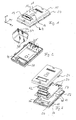
- Fig. 1 shows a perspective view of the housing 10 according to the invention.
- the housing 10 has a substantially rectangular shape, wherein the housing forms a cuboid in its basic form. Referring to the drawn tripod in Fig. 1, the housing 10 has its greatest length in the Y direction and a width in the X direction, which is slightly more than half the length. The height in the Z direction of the housing is approximately one quarter of the width.
- upwardly facing surface 12 of the housing 10 has approximately centrally a rectangular membrane field 16. Also, from the surface 12 is a rectangular boundary wall 14 for a connector before.
- a field 18 is provided on the top 12 of the housing 10, which serves for example for attaching a nameplate.
- the upper shell of the housing has a circumferential bead 20, which opens at its lower end into a sealing lip 22.
- the transition between the side wall of the upper shell and the bead 20 is slightly rounded.
- On each longitudinal side (Y direction) of the upper housing shell two U-shaped snap closures 24 are provided.
- the snap fasteners 24 each have a rectangular opening 26 and a snap edge 28 extending over the entire width of the closure.
- the upper shell of the housing 10 has on its inside four parallel to a narrow edge (X-axis) arranged locking pins 30 which have latching lugs 32 at its lower, facing the inside of the upper shell end.
- a coil spring 34 is inserted in each case, which is locked on the pin and held so for later assembly.
- a partition wall 36 is provided on the inside of the upper shell.
- the partition wall 36 serves as additional support for the upper housing shell.
- the opening 38 is also good to see over which projects the side wall 14 of the electrical connection. As clearly shown in Figs. 2 and 4, the opening 38 has a peripheral sealing edge 40th
- the counterpart to the upper housing shell forms the bottom element 42, which is formed as a solid metal body.
- the bottom element 42 has a groove 44, in which a sealing element 46 is arranged.
- the bottom of the bottom element 42 has a large depression 48, in FIG which are provided in the region of the connectors two parallel to each other in the Y direction extending support projections 50.
- the support projections 50 are flush with the bottom 52 of the bottom member 42 in the non-recessed portion.
- an insulating film 54 is provided, which separates the circuit board 58 from the bottom element 42.
- the circuit board 58 is not fully populated in the illustrated embodiment for clarity.
- the receptacle 60 for the electrical connector has a series of electrical contacts 62, three of which are shown in the drawings by way of example.
- the receptacle has the above-mentioned circumferential wall 14. The reason of the receptacle 60 is increased relative to the circuit board 58.
- a seal 62 is arranged, which seals the opening 38 with the sealing edge 40 in the upper shell of the housing relative to the terminal 60.
- the bottom member has recesses 64 laterally with a central snap nose 66 which cooperates with the snap edge 28 of the snap closure 24. This is behind the Snap nose 66 on the opening 26, the lower web of the snap closure 24th
- the four springs 34 are placed on the pins 30 in a first step until they are locked. Subsequently, the insulating film 54 is placed on the base 52 and aligned over the centering pin 56. Subsequently, the circuit board 58 is placed on the bottom member 52 and also aligned with the centering pins 56. In a further step, the upper part of the housing is placed with the sealing ring 62, so that the connection for the connector protrudes from the housing. Subsequently, this is closed by a strong compression of the housing on the snap closures.
- the printed circuit board 28 is then securely held in the housing.
- the housing is attached to the vehicle frame so that no water stops on the lid, but flows directly.
- the rectangular membrane field 16 is covered with a fabric, preferably a water-impermeable fabric.
- the fabric is designed to be permeable to water vapor and air. Such a permeable fabric ensures that in a pressure equalization due to a change in temperature no water in liquid form, but only enters the control in vapor form. As a result, the controller does not have to be pressure-tight sealed and it is still avoided the entry of water into the controller.
Landscapes
- Engineering & Computer Science (AREA)
- Microelectronics & Electronic Packaging (AREA)
- Casings For Electric Apparatus (AREA)
- Cookers (AREA)
- Connector Housings Or Holding Contact Members (AREA)
- Cooling Or The Like Of Electrical Apparatus (AREA)
Abstract
Description
- Die vorliegende Erfindung betrifft ein Gehäuse für eine Steuerung, das eine Aufnahme für einen Steckverbinder mit elektrischen Kontakten besitzt.
- Das Gehäuse für eine Steuerung, die beispielsweise einen durch eine Person zu bedienenden Taster oder ein ähnliches Steuerelement besitzt, ist bei einem Arbeitseinsatz, beispielsweise im Bereich der Logistik, hohen Belastungen durch Stöße, Wasser- oder sonstige Umwelteinflüsse ausgesetzt. Gehäuse für Steuerungen wurden daher in der Vergangenheit stets, aus zwei miteinander verschraubten Schalen hergestellt, was zu entsprechend langen Herstellzeiten geführt hat.
- Der Erfindung liegt die Aufgabe zugrunde, ein Gehäuse für eine Steuerung bereitzustellen, das stabil und robust ausgebildet ist und sich auch entsprechend schnell und leicht montieren läßt.
- Die erfindungsgemäße Aufgabe wird durch ein Gehäuse mit den Merkmalen aus Anspruch 1 gelöst. Vorteilhafte Ausgestaltungen bilden den Gegenstand der Unteransprüche.
- Das erfindungsgemäße Gehäuse ist für eine Steuerung vorgesehen und besitzt eine obere Schale, ein Bodenelement und eine Leiterplatte. Die Leiterplatte ist mit einer Aufnahme für einen Steckverbinder mit elektrischen Anschlüssen versehen. Die obere Schale besitzt eine Durchbrechung durch die die Aufnahme für den Steckverbinder von außen zugänglich ist. Erfindungsgemäß sind obere Schale und Bodenelement über Schnappverschlüsse dichtend miteinander verbunden. Die Leiterplatte ist über mindestens ein elastisches Element zwischen oberer und unterer Schale gehalten. Bei der erfindungsgemäßen Ausgestaltung ist es nicht länger erforderlich, die Leiterplatte an einer der Schalen zu verschrauben oder die Schalen miteinander zu verschrauben. Über die Schnappverschlüsse werden obere Schale und Bodenelement aneinander gehalten und die Leiterplatte über mindestens ein elastisches Element zwischen den beiden Schalen gehalten. Hierdurch wird der Aufwand bei der Montage deutlich reduziert.
- In einer bevorzugten Ausgestaltung für das erfindungsgemäße Gehäuse ist das Bodenelement als Kühlkörper für Transistoren und andere Bauteile auf der Leiterplatte ausgebildet. Gleichzeitig bietet das Bodenelement somit auch einen ausreichenden Schutz und eine ausreichende Stabilität für das gesamte Gehäuse.
- In einer bevorzugten Ausgestaltung ist mindestens ein elastisches Element in der oberen Schale gehalten. Hierdurch wird wiederum bei der Montage des Gehäuses sichergestellt, daß die elastischen Elemente richtig im Gehäuseinneren positioniert sind.
- Nach der bevorzugten Ausgestaltung ist das elastische Element als ein Federelement ausgebildet, das im geschlossenen Zustand des Gehäuses die Leiterplatte gegen Bodenelement drückt. Hierdurch wird einerseits die Leiterplatte in dem Gehäuse gehalten und andererseits die Leiterplatte zur Wärmeableitung gegen das Bodenelement gedrückt.
- In einer bevorzugten Ausgestaltung sind auf der Innenseite der oberen Schale Stifte vorgesehen, die senkrecht in den Innenraum vorstehen und auf die jeweils ein Federelement gesetzt ist. Das Federelement drückt die Leiterplatte gegen das Bodenelement.
- Bevorzugt besitzen die Stifte Rastmittel, über die das Federelement auf den Stiften gehalten ist.
- In einer zweckmäßigen Ausgestaltung ist die Aufnahme für den Steckverbinder über eine umlaufende Dichtung gegenüber der oberen Schale abgedichtet, wobei die obere Schale über das Dichtelement die Leiterplatte gegen das Bodenelement drückt. Das Dichtelement dient ebenso wie das Federelement dazu, die Leiterplatte gegen das Bodenelement zu drücken. Hierdurch wird ein fester Sitz der Leiterplatte in dem Gehäuse sichergestellt.
- In einer bevorzugten Ausgestaltung besitzt die Leiterplatte mindestens eine Durchbrechung, wobei mindestens eine der Schalen mit einem zugehörigen Zentrierstift ausgestattet ist, um die Position der Leiterplatte relativ zu der Schale festzulegen.
- Eine bevorzugte Ausgestaltung des erfindungsgemäßen Gehäuses wird nachfolgend anhand eines Beispiels näher erläutert.
- Es zeigt:
- Fig. 1
- eine perspektivische Ansicht des erfindungsgemäßen Gehäuses im geschlossenen Zustand,
- Fig. 2
- eine perspektivische Ansicht zu der oberen Schale des Gehäuses,
- Fig. 3
- eine Explosionsdarstellung in einer perspektivischen Ansicht und
- Fig. 4
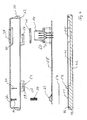
- eine auseinandergezogene Darstellung in einer Schnittansicht.
- Fig. 1 zeigt in einer perspektivischen Ansicht das erfindungsgemäße Gehäuse 10. Das Gehäuse 10 besitzt eine im wesentlichen rechteckige Form, wobei das Gehäuse in seiner Grundform einen Quader bildet. Bezogen auf das eingezeichnete Dreibein in Fig. 1 besitzt das Gehäuse 10 seine größte Länge in Y-Richtung und eine Breite in X-Richtung, die etwas mehr als die Hälfte der Länge beträgt. Die Höhe in Z-Richtung des Gehäuses beträgt ungefähr ein viertel der Breite. Die in Fig. 1 nach oben weisende Fläche 12 des Gehäuses 10 besitzt ungefähr mittig ein rechteckiges Membranfeld 16. Ebenfalls steht aus der Fläche 12 eine rechteckige Begrenzungswand 14 für eine Steckverbindung vor. Zusätzlich ist auf der Oberseite 12 des Gehäuses 10 ein Feld 18 vorgesehen, das beispielsweise zur Befestigung eines Typenschilds dient.
- Die obere Schale des Gehäuses besitzt einen umlaufenden Wulst 20, der an seinem unteren Ende in eine Dichtlippe 22 mündet. Der Übergang zwischen der Seitenwand der oberen Schale und der Wulst 20 ist leicht abgerundet. Auf jeder Längsseite (Y-Richtung) der oberen Gehäuseschale sind zwei U-förmige Schnappverschlüsse 24 vorgesehen. Die Schnappverschlüsse 24 besitzen jeweils eine rechteckige Durchbrechung 26 und eine über die gesamte Breite des Verschlusses sich erstreckende Schnappkante 28.
- Wie in Fig. 2 dargestellt besitzt die obere Schale des Gehäuses 10 auf Ihrer Innenseite vier parallel zu einer Schmalkante (X-Achse) angeordnete Raststifte 30, die an ihrem unteren, zur Innenseite der oberen Schale weisenden Ende Rastnasen 32 besitzen. Auf die Stifte 30 ist jeweils eine Spiralfeder 34 gesteckt, die auf dem Stift verrastet und so für eine spätere Montage gehalten wird.
- Parallel zu den Stiften 30 ist auf der Innenseite der oberen Schale eine Trennwand 36 vorgesehen. Die Trennwand 36 dient als zusätzliche Abstützung für die obere Gehäuseschale.
- In Fig. 2 ist ebenfalls gut die Durchbrechung 38 zu erkennen, über die die Seitenwand 14 des elektrischen Anschlusses vorsteht. Wie deutlich in Fign. 2 und 4 zu erkennen, besitzt die Durchbrechung 38 eine umlaufende Dichtkante 40.
- Das Gegenstück zu der oberen Gehäuseschale bildet das Bodenelement 42, das als massiver Metallkörper ausgebildet ist. Umlaufend besitzt das Bodenelement 42 eine Nut 44, in der ein Dichtelement 46 angeordnet ist. Der Grund von dem Bodenelement 42 besitzt eine großflächige Vertiefung 48, in der im Bereich der Steckverbindungen zwei parallel zueinander sich in Y-Richtung erstreckende Abstützvorsprünge 50 vorgesehen sind. Die Abstützvorsprünge 50 schließen bündig mit dem Grund 52 des Bodenelements 42 in dem nicht vertieften Abschnitt ab. Aus dem Grund 52 des Bodenelements 42 stehen Zentrierstifte 56 vor. In dem Bereich, in dem das Bodenelement keine Vertiefung 48 besitzt, ist eine Isolierfolie 54 vorgesehen, die die Leiterplatte 58 von dem Bodenelement 42 trennt. Die Leiterplatte 58 ist in dem dargestellten Ausführungsbeispiel zur besseren Übersicht nicht vollständig bestückt. Lediglich die Aufnahme für den elektrischen Steckverbinder 60 sowie Transistoren 62 sind auf der Leiterplatte 18 dargestellt. Die Feder 34 drückt auf die Transistoren 62, so daß die Leiterplatte 58 im Bereich der Transistoren 62 gegen die Isolierfolie 54 auf das Bodenelement 42 gedrückt wird. Durch den engen Kontakt erfolgt eine besonders gute Wärmeableitung von den Transistoren 62 hin zu dem Bodenelement 42, das aus Metall hergestellt ist. Die Aufnahme 60 für den elektrischen Steckverbinder besitzt eine Reihe von elektrischen Kontakten 62, von denen in den Zeichnungen beispielhaft drei dargestellt sind. Die Aufnahme besitzt die bereits oben angesprochene umlaufende Wand 14. Der Grund der Aufnahme 60 ist gegenüber der Leiterplatte 58 erhöht. Um die Umgrenzungswand 14 ist eine Dichtung 62 angeordnet, die die Durchbrechung 38 mit der Dichtkante 40 in der oberen Schale des Gehäuses gegenüber dem Anschluß 60 abdichtet.
- Wie in Fig. 3 dargestellt besitzt das Bodenelement seitlich Vertiefungen 64 mit einer zentralen Schnappnase 66, die mit der Schnappkante 28 des Schnappverschlusses 24 zusammenwirkt. Hierbei hintergreift die Schnappnase 66 über die Durchbrechung 26 den unteren Steg des Schnappverschlusses 24.
- Zur Montage des Gehäuses werden in einem ersten Schritt die vier Federn 34 auf die Stifte 30 aufgesetzt, bis diese verrastet sind. Anschließend wird die Isolierfolie 54 auf dem Grund 52 gelegt und über den Zentrierstift 56 ausgerichtet. Nachfolgend wird die Leiterplatte 58 auf das Bodenelement 52 gelegt und ebenfalls anhand der Zentrierstifte 56 ausgerichtet. In einem weiteren Schritt wird das Oberteil des Gehäuses bei aufgesetztem Dichtring 62 aufgesetzt, so daß der Anschluß für die Steckverbindung aus dem Gehäuse herausragt. Anschließend wird durch ein kräftiges Zusammendrücken des Gehäuses dieses über die Schnappverschlüsse verschlossen.
- Bei dem erfindungsgemäßen Gehäuse ist dann die Leiterplatte 28 sicher in dem Gehäuse gehalten.
- Das Gehäuse wird an dem Fahrzeugrahmen so befestigt, daß kein Wasser auf dem Deckel stehen bleibt, sondern direkt abfließt. Das rechteckige Membranfeld 16 ist mit einem Stoffgewebe, bevorzugt einem wasserundurchlässigen Gewebe abgedeckt. Das Gewebe ist ausgebildet, um für Wasserdampf und Luft durchlässig zu sein. Ein solches permeables Gewebe stellt sicher, daß bei einem Druckausgleich aufgrund einer Temperaturänderung kein Wasser in flüssiger Form, sondern nur dampfförmig in die Steuerung gelangt. Dadurch muß die Steuerung nicht druckfest abgedichtet sein und es wird trotzdem der Eintritt von Wasser in die Steuerung vermieden.
Claims (9)
- Gehäuse für eine Steuerung mit einer oberen Schale (12), einem Bodenelement (42) und einer Leiterplatte (58), auf der eine Aufnahme für eine Steckverbindung (60) mit elektrischen Anschlüssen vorgesehen ist, die über eine Durchbrechung (38) in der oberen Schale von außen zugänglich ist, dadurch gekennzeichnet, daß obere Schale und Bodenelement mit Schnappverschlüssen (24) dichtend miteinander verbunden sind und die Leiterplatte über mindestens ein elastisches Element (34) zwischen oberer Schale und Bodenelement gehalten ist.
- Gehäuse nach Anspruch 1, dadurch gekennzeichnet, daß das Bodenelement (42) aus Metall hergestellt ist.
- Gehäuse nach Anspruch 2, dadurch gekennzeichnet, daß die Leiterplatte (58) in mindestens einem Abschnitt flächig an dem Bodenelement anliegt.
- Gehäuse nach einem der Ansprüche 1 bis 3, dadurch gekennzeichnet, daß das elastische Element in der oberen Schale gehalten ist.
- Gehäuse nach einem der Ansprüche 1 bis 4, dadurch gekennzeichnet, daß das elastische Element als ein Federelement ausgebildet ist, das im geschlossenen Zustand des Gehäuses die Leiterplatte (58) gegen das Bodenelement drückt.
- Gehäuse nach Anspruch 5, dadurch gekennzeichnet, daß auf der Innenseite der oberen Schäle mindestens ein Stift (30) vorgesehen ist, der senkrecht in den Innenraum vorsteht und auf den jeweils das Federelement (34) gesetzt ist.
- Gehäuse nach Anspruch 6, dadurch gekennzeichnet, daß der mindestens eine Stift (30) Rastmittel (32) für das Federelement (34) besitzt.
- Gehäuse nach einem der Ansprüche 1 bis 6, dadurch gekennzeichnet, daß die Aufnahme (60) für den elektrischen Steckverbinder über ein umlaufendes Dichtelement (62) gegenüber der oberen Schale abgedichtet ist, wobei die obere Schale über das Dichtelement die Leiterplatte (58) gegen das Bodenelement (42) drückt.
- Gehäuse nach einem der Ansprüche 1 bis 8, dadurch gekennzeichnet, daß die Leiterplatte (58) mindestens eine Durchbrechung (38) besitzt und das Bodenelement mindestens einen entsprechend positionierten Zentrierstift.
Applications Claiming Priority (1)
| Application Number | Priority Date | Filing Date | Title |
|---|---|---|---|
| DE200610034923 DE102006034923A1 (de) | 2006-07-28 | 2006-07-28 | Gehäuse für eine Steuerung |
Publications (3)
| Publication Number | Publication Date |
|---|---|
| EP1883284A2 true EP1883284A2 (de) | 2008-01-30 |
| EP1883284A3 EP1883284A3 (de) | 2008-12-03 |
| EP1883284B1 EP1883284B1 (de) | 2011-06-29 |
Family
ID=38723338
Family Applications (1)
| Application Number | Title | Priority Date | Filing Date |
|---|---|---|---|
| EP20070012980 Active EP1883284B1 (de) | 2006-07-28 | 2007-07-03 | Gehäuse für eine Steuerung |
Country Status (2)
| Country | Link |
|---|---|
| EP (1) | EP1883284B1 (de) |
| DE (1) | DE102006034923A1 (de) |
Cited By (6)
| Publication number | Priority date | Publication date | Assignee | Title |
|---|---|---|---|---|
| EP2117287A1 (de) * | 2008-04-11 | 2009-11-11 | Tac AB | Gehäuse für eine Elektroschaltung für ein Gebäudekontrollsystem |
| US7994438B2 (en) | 2008-04-11 | 2011-08-09 | Schneider Electric Buildings Llc | Housing for an electronic circuit intended for a building control system |
| EP2545621A1 (de) * | 2010-03-11 | 2013-01-16 | Robert Bosch GmbH | Gehäusegrundelement eines mehrteiligen gehäuses und verfahren zur montage eines gehäuses |
| CN105430950A (zh) * | 2015-12-24 | 2016-03-23 | 中国船舶重工集团公司第七一一研究所 | 一种电动执行器智能化模块封装结构的设计方法 |
| CN108307592A (zh) * | 2017-01-09 | 2018-07-20 | 翰昂汽车零部件有限公司 | 用于容纳和支承汇流条的装置 |
| WO2025002702A1 (fr) * | 2023-06-30 | 2025-01-02 | Continental Automotive Technologies GmbH | Boîtier électronique comprenant une carte électronique portant des connecteurs |
Families Citing this family (4)
| Publication number | Priority date | Publication date | Assignee | Title |
|---|---|---|---|---|
| DE102012203634B4 (de) * | 2012-03-08 | 2013-12-12 | Continental Automotive Gmbh | Steuergerät zur Verwendung in einem Kraftfahrzeug |
| DE102013017215A1 (de) | 2013-10-16 | 2015-04-16 | Wabco Gmbh | Elektronikgehäuse |
| DE202018101328U1 (de) * | 2018-03-09 | 2018-04-30 | Andreas Körner | Temperaturregulierende Tragenauflage |
| DE102022105517A1 (de) * | 2022-03-09 | 2023-09-14 | Kiekert Aktiengesellschaft | Schloss für ein Kraftfahrzeug |
Citations (3)
| Publication number | Priority date | Publication date | Assignee | Title |
|---|---|---|---|---|
| US5552961A (en) | 1995-05-18 | 1996-09-03 | Northern Telecom Limited | Electronic unit |
| EP0792094A1 (de) | 1996-02-24 | 1997-08-27 | Robert Bosch Gmbh | Elektronisches Steuergerät |
| US6331937B1 (en) | 1999-07-28 | 2001-12-18 | Dell Usa, L.P. | Apparatus and method for securing a heat sink to an electronic component in a computer system |
Family Cites Families (8)
| Publication number | Priority date | Publication date | Assignee | Title |
|---|---|---|---|---|
| DE4023319C1 (de) * | 1990-07-21 | 1991-12-12 | Robert Bosch Gmbh, 7000 Stuttgart, De | |
| US6058024A (en) * | 1997-07-17 | 2000-05-02 | Tektronix, Inc. | Electronic instrument with electromagnetic interference shield and method of manufacturing |
| DE10013116B4 (de) * | 2000-03-17 | 2008-01-03 | Aeg Niederspannungstechnik Gmbh & Co Kg | Vorrichtung zur lagerichtigen Befestigung einer Leiterplatte |
| US6445588B1 (en) * | 2001-01-02 | 2002-09-03 | Motorola, Inc. | Apparatus and method for securing a printed circuit board to a base plate |
| DE10161104C1 (de) * | 2001-12-12 | 2003-07-10 | Knorr Bremse Systeme | Elektrisches Steuergerät sowie Herstellungsverfahren |
| DE10246095B4 (de) * | 2002-10-02 | 2004-12-16 | Siemens Ag | Elektronisches Gerät mit schwimmend gelagertem Schaltungsträger |
| US6995982B2 (en) * | 2002-12-12 | 2006-02-07 | Dell Products L.P. | Spring loaded plunger for circuit board installation and removal |
| US6937475B2 (en) * | 2003-09-04 | 2005-08-30 | Dell Products L.P. | Mounting and grounding assembly for circuit board mounted parallel to chassis bottom |
-
2006
- 2006-07-28 DE DE200610034923 patent/DE102006034923A1/de not_active Withdrawn
-
2007
- 2007-07-03 EP EP20070012980 patent/EP1883284B1/de active Active
Patent Citations (3)
| Publication number | Priority date | Publication date | Assignee | Title |
|---|---|---|---|---|
| US5552961A (en) | 1995-05-18 | 1996-09-03 | Northern Telecom Limited | Electronic unit |
| EP0792094A1 (de) | 1996-02-24 | 1997-08-27 | Robert Bosch Gmbh | Elektronisches Steuergerät |
| US6331937B1 (en) | 1999-07-28 | 2001-12-18 | Dell Usa, L.P. | Apparatus and method for securing a heat sink to an electronic component in a computer system |
Cited By (8)
| Publication number | Priority date | Publication date | Assignee | Title |
|---|---|---|---|---|
| EP2117287A1 (de) * | 2008-04-11 | 2009-11-11 | Tac AB | Gehäuse für eine Elektroschaltung für ein Gebäudekontrollsystem |
| US7994438B2 (en) | 2008-04-11 | 2011-08-09 | Schneider Electric Buildings Llc | Housing for an electronic circuit intended for a building control system |
| EP2545621A1 (de) * | 2010-03-11 | 2013-01-16 | Robert Bosch GmbH | Gehäusegrundelement eines mehrteiligen gehäuses und verfahren zur montage eines gehäuses |
| CN105430950A (zh) * | 2015-12-24 | 2016-03-23 | 中国船舶重工集团公司第七一一研究所 | 一种电动执行器智能化模块封装结构的设计方法 |
| CN105430950B (zh) * | 2015-12-24 | 2018-06-05 | 中国船舶重工集团公司第七一一研究所 | 一种电动执行器智能化模块封装结构的设计方法 |
| CN108307592A (zh) * | 2017-01-09 | 2018-07-20 | 翰昂汽车零部件有限公司 | 用于容纳和支承汇流条的装置 |
| WO2025002702A1 (fr) * | 2023-06-30 | 2025-01-02 | Continental Automotive Technologies GmbH | Boîtier électronique comprenant une carte électronique portant des connecteurs |
| FR3150655A1 (fr) * | 2023-06-30 | 2025-01-03 | Continental Automotive Technologies GmbH | Boîtier électronique comprenant une carte électronique portant des connecteurs |
Also Published As
| Publication number | Publication date |
|---|---|
| EP1883284B1 (de) | 2011-06-29 |
| DE102006034923A1 (de) | 2008-01-31 |
| EP1883284A3 (de) | 2008-12-03 |
Similar Documents
| Publication | Publication Date | Title |
|---|---|---|
| EP1883284B1 (de) | Gehäuse für eine Steuerung | |
| EP0705183B1 (de) | Anbausteuergerät | |
| EP0555434B1 (de) | Elektrisches gerät, insbesondere schalt- und steuergerät für kraftfahrzeuge | |
| EP1814202B1 (de) | Kupplung | |
| DE102007042173B4 (de) | Radarsensor | |
| DE112011105716B4 (de) | Elektronische Schaltungseinheit mit Fähigkeit zur externen Verbindung | |
| DE112017003846T5 (de) | Leistungsanschluss für einen elektrischen Verbinder | |
| DE102008028933A1 (de) | Stromkreisunterbrechungsvorrichtung | |
| DE4406644A1 (de) | Steckkarte für elektronische Datenverarbeitungsgeräte und Verfahren zu dessen Herstellung und Montage | |
| DE102015220949A1 (de) | Elektronische Einrichtung | |
| WO2012010152A2 (de) | Elektrische baugruppe für ein kraftfahrzeug geeignet zur kontaktierung mit einem stecker | |
| DE102007009644B4 (de) | Mechatronische Baugruppe mit Steckverbindung | |
| DE102007038538A1 (de) | Gehäuse für eine elektrische Schaltung, insbesondere eines Steuergeräts eines Fahrzeugs | |
| DE102014205744B4 (de) | Steuergerät für ein Fahrzeugheizgerät | |
| EP1976357B1 (de) | Gehäuse für eine elektrische Schaltung und Verfahren zum Schließen eines entsprechenden Gehäuses | |
| DE19534205C2 (de) | Elektrischer Steckverbinder | |
| EP1282345B1 (de) | Gehäuse zur Aufnahme einer Leiterplatte mit elektronischen Bauteilen in Fahrzeugen | |
| EP2688151A1 (de) | Verbindungseinrichtung für Leistungshalbleitereinrichtung mit dichtem Steckverbinder | |
| DE102006007604A1 (de) | Kabelanschlussvorrichtung zum Übertragen elektrischer Antriebsleistung und Verbindungsanordnung mit einer solchen Kabelanschlussvorrichtung | |
| EP4500637A1 (de) | Erdungsmodul zur aufnahme in einen metallischen steckverbindermodularrahmen und zur erdung desselben | |
| DE112017000903T5 (de) | Abdeckungsanordnung und elektrische Verbinderanordnung | |
| DE102005053014A1 (de) | Drucksensorgehäuse und Verfahren zu seiner Herstellung | |
| DE60038709T2 (de) | Wasserdichte Abdichtungsanordnung für Verbinder | |
| DE102012213200B4 (de) | Elektronische Steuereinheit | |
| DE102009040446A1 (de) | Verbinderanordnung zur Befestigung an einer Platte |
Legal Events
| Date | Code | Title | Description |
|---|---|---|---|
| PUAI | Public reference made under article 153(3) epc to a published international application that has entered the european phase |
Free format text: ORIGINAL CODE: 0009012 |
|
| AK | Designated contracting states |
Kind code of ref document: A2 Designated state(s): AT BE BG CH CY CZ DE DK EE ES FI FR GB GR HU IE IS IT LI LT LU LV MC MT NL PL PT RO SE SI SK TR |
|
| AX | Request for extension of the european patent |
Extension state: AL BA HR MK YU |
|
| PUAL | Search report despatched |
Free format text: ORIGINAL CODE: 0009013 |
|
| AK | Designated contracting states |
Kind code of ref document: A3 Designated state(s): AT BE BG CH CY CZ DE DK EE ES FI FR GB GR HU IE IS IT LI LT LU LV MC MT NL PL PT RO SE SI SK TR |
|
| AX | Request for extension of the european patent |
Extension state: AL BA HR MK RS |
|
| RIC1 | Information provided on ipc code assigned before grant |
Ipc: H05K 7/14 20060101ALI20081030BHEP Ipc: H05K 5/06 20060101ALI20081030BHEP Ipc: H05K 5/02 20060101AFI20071207BHEP |
|
| 17P | Request for examination filed |
Effective date: 20081206 |
|
| AKX | Designation fees paid |
Designated state(s): DE FR GB IT SE |
|
| GRAP | Despatch of communication of intention to grant a patent |
Free format text: ORIGINAL CODE: EPIDOSNIGR1 |
|
| GRAS | Grant fee paid |
Free format text: ORIGINAL CODE: EPIDOSNIGR3 |
|
| GRAA | (expected) grant |
Free format text: ORIGINAL CODE: 0009210 |
|
| AK | Designated contracting states |
Kind code of ref document: B1 Designated state(s): DE FR GB IT SE |
|
| REG | Reference to a national code |
Ref country code: GB Ref legal event code: FG4D Free format text: NOT ENGLISH |
|
| REG | Reference to a national code |
Ref country code: DE Ref legal event code: R096 Ref document number: 502007007532 Country of ref document: DE Effective date: 20110818 |
|
| PG25 | Lapsed in a contracting state [announced via postgrant information from national office to epo] |
Ref country code: SE Free format text: LAPSE BECAUSE OF FAILURE TO SUBMIT A TRANSLATION OF THE DESCRIPTION OR TO PAY THE FEE WITHIN THE PRESCRIBED TIME-LIMIT Effective date: 20110629 |
|
| PLBE | No opposition filed within time limit |
Free format text: ORIGINAL CODE: 0009261 |
|
| STAA | Information on the status of an ep patent application or granted ep patent |
Free format text: STATUS: NO OPPOSITION FILED WITHIN TIME LIMIT |
|
| 26N | No opposition filed |
Effective date: 20120330 |
|
| REG | Reference to a national code |
Ref country code: DE Ref legal event code: R097 Ref document number: 502007007532 Country of ref document: DE Effective date: 20120330 |
|
| REG | Reference to a national code |
Ref country code: FR Ref legal event code: PLFP Year of fee payment: 10 |
|
| REG | Reference to a national code |
Ref country code: FR Ref legal event code: PLFP Year of fee payment: 11 |
|
| PGFP | Annual fee paid to national office [announced via postgrant information from national office to epo] |
Ref country code: FR Payment date: 20170727 Year of fee payment: 11 Ref country code: GB Payment date: 20170728 Year of fee payment: 11 Ref country code: IT Payment date: 20170720 Year of fee payment: 11 |
|
| GBPC | Gb: european patent ceased through non-payment of renewal fee |
Effective date: 20180703 |
|
| PG25 | Lapsed in a contracting state [announced via postgrant information from national office to epo] |
Ref country code: FR Free format text: LAPSE BECAUSE OF NON-PAYMENT OF DUE FEES Effective date: 20180731 Ref country code: GB Free format text: LAPSE BECAUSE OF NON-PAYMENT OF DUE FEES Effective date: 20180703 |
|
| PG25 | Lapsed in a contracting state [announced via postgrant information from national office to epo] |
Ref country code: IT Free format text: LAPSE BECAUSE OF NON-PAYMENT OF DUE FEES Effective date: 20180703 |
|
| PGFP | Annual fee paid to national office [announced via postgrant information from national office to epo] |
Ref country code: DE Payment date: 20250722 Year of fee payment: 19 |