EP1883161A2 - Combined LDPC (low density parity check) encoder and syndrome checker - Google Patents
Combined LDPC (low density parity check) encoder and syndrome checker Download PDFInfo
- Publication number
- EP1883161A2 EP1883161A2 EP07007455A EP07007455A EP1883161A2 EP 1883161 A2 EP1883161 A2 EP 1883161A2 EP 07007455 A EP07007455 A EP 07007455A EP 07007455 A EP07007455 A EP 07007455A EP 1883161 A2 EP1883161 A2 EP 1883161A2
- Authority
- EP
- European Patent Office
- Prior art keywords
- coded signal
- ldpc
- ldpc coded
- circuitry
- matrix
- Prior art date
- Legal status (The legal status is an assumption and is not a legal conclusion. Google has not performed a legal analysis and makes no representation as to the accuracy of the status listed.)
- Granted
Links
Images


Classifications
-
- H—ELECTRICITY
- H03—ELECTRONIC CIRCUITRY
- H03M—CODING; DECODING; CODE CONVERSION IN GENERAL
- H03M13/00—Coding, decoding or code conversion, for error detection or error correction; Coding theory basic assumptions; Coding bounds; Error probability evaluation methods; Channel models; Simulation or testing of codes
- H03M13/03—Error detection or forward error correction by redundancy in data representation, i.e. code words containing more digits than the source words
- H03M13/05—Error detection or forward error correction by redundancy in data representation, i.e. code words containing more digits than the source words using block codes, i.e. a predetermined number of check bits joined to a predetermined number of information bits
- H03M13/11—Error detection or forward error correction by redundancy in data representation, i.e. code words containing more digits than the source words using block codes, i.e. a predetermined number of check bits joined to a predetermined number of information bits using multiple parity bits
- H03M13/1102—Codes on graphs and decoding on graphs, e.g. low-density parity check [LDPC] codes
- H03M13/1105—Decoding
-
- H—ELECTRICITY
- H03—ELECTRONIC CIRCUITRY
- H03M—CODING; DECODING; CODE CONVERSION IN GENERAL
- H03M13/00—Coding, decoding or code conversion, for error detection or error correction; Coding theory basic assumptions; Coding bounds; Error probability evaluation methods; Channel models; Simulation or testing of codes
- H03M13/03—Error detection or forward error correction by redundancy in data representation, i.e. code words containing more digits than the source words
- H03M13/05—Error detection or forward error correction by redundancy in data representation, i.e. code words containing more digits than the source words using block codes, i.e. a predetermined number of check bits joined to a predetermined number of information bits
- H03M13/11—Error detection or forward error correction by redundancy in data representation, i.e. code words containing more digits than the source words using block codes, i.e. a predetermined number of check bits joined to a predetermined number of information bits using multiple parity bits
-
- H—ELECTRICITY
- H03—ELECTRONIC CIRCUITRY
- H03M—CODING; DECODING; CODE CONVERSION IN GENERAL
- H03M13/00—Coding, decoding or code conversion, for error detection or error correction; Coding theory basic assumptions; Coding bounds; Error probability evaluation methods; Channel models; Simulation or testing of codes
- H03M13/65—Purpose and implementation aspects
- H03M13/6502—Reduction of hardware complexity or efficient processing
Definitions
- the invention relates generally to communication systems; and, more particularly, it relates to encoding and decoding processing of LDPC (Low Density Parity Check) signals within such communication systems.
- LDPC Low Density Parity Check
- Shannon's limit may be viewed as being the data rate to be used in a communication channel, having a particular SNR, that achieves error free transmission through the communication channel.
- the Shannon limit is the theoretical bound for channel capacity for a given modulation and code rate.
- LDPC code has been shown to provide for excellent decoding performance that can approach the Shannon limit in some cases. For example, some LDPC decoders have been shown to come within 0.3 dB (decibels) from the theoretical Shannon limit. While this example was achieved using an irregular LDPC code of a length of one million, it nevertheless demonstrates the very promising application of LDPC codes within communication systems.
- first communication device at one end of a communication channel with encoder capability and second communication device at the other end of the communication channel with decoder capability.
- second communication device at the other end of the communication channel with decoder capability.
- encoder and decoder capability e.g., within a bi-directional communication system.
- the present invention is directed to apparatus and methods of operation that are further described in the following Brief Description of the Several Views of the Drawings, the Detailed Description of the Invention, and the claims.
- an apparatus comprises:
- the parity bit is a first parity bit; the first parity bit is provided to a portion of the circuitry that is operable to calculate a second parity bit; and the first information bit, the first parity bit, and the second parity bit form at least part of the first LDPC coded signal.
- the first LDPC coded signal is launched into a communication channel; and the second LDPC coded signal is received from the communication channel.
- the first LDPC coded signal is launched into a communication channel; the second LDPC coded signal is received from the communication channel; and the communication channel is a read channel that is coupled to a storage media of a hard disk drive (HDD).
- HDD hard disk drive
- the apparatus further comprises:
- the first LDPC coded signal is launched into a communication channel during a first time; and the second LDPC coded signal is received from the communication channel during a second time; and further comprising:
- the LDPC matrix corresponds to an LDPC code that is systematic.
- the LDPC matrix can partitioned into a first sub-matrix and a second sub-matrix; the second sub-matrix includes at least one column of the LDPC matrix that is employed to generate the parity bit; the second sub-matrix is a lower triangular matrix such that each non-zero valued element within the second sub-matrix is situated either along a diagonal of the second sub-matrix or below the diagonal of the second sub-matrix; and the diagonal being defined as traversing the second sub-matrix from an upper-left-most element of the second sub-matrix to a lower-right-most element of the second sub-matrix.
- an apparatus comprises:
- a method comprises:
- the method further comprises:
- a memory can be implemented to allow for memory management of one of the signals while the other is being processed (e.g., within a ping-pong memory configuration or other memory configuration which allows for use of the shared processing resources for a first signal during a first time and use of the shared processing resources for a second signal during a second time).
- the goal of digital communications systems is to transmit digital data from one location, or subsystem, to another either error free or with an acceptably low error rate.
- data may be transmitted over a variety of communications channels in a wide variety of communication systems: magnetic media, wireless, fiber, copper, and other types of media as well.
- FIG. 1 is a diagram illustrating an embodiment of a communication system 100.
- this embodiment of a communication system 100 is a communication channel 199 that communicatively couples a communication device 110 (including a transmitter 112 having an encoder 114 and including a receiver 116 having a decoder 118) situated at one end of the communication channel 199 to another communication device 120 (including a transmitter 126 having an encoder 128 and including a receiver 122 having a decoder 124) at the other end of the communication channel 199.
- a communication device 110 including a transmitter 112 having an encoder 114 and including a receiver 116 having a decoder 118
- another communication device 120 including a transmitter 126 having an encoder 128 and including a receiver 122 having a decoder 124
- either of the communication devices 110 and 120 may only include a transmitter or a receiver.
- the communication channel 199 may be implemented (e.g., a satellite communication channel 130 using satellite dishes 132 and 134, a wireless communication channel 140 using towers 142 and 144 and/or local antennae 152 and 154, a wired communication channel 150, and/or a fiber-optic communication channel 160 using electrical to optical (E/O) interface 162 and optical to electrical (O/E) interface 164)).
- a satellite communication channel 130 using satellite dishes 132 and 134 e.g., a satellite communication channel 130 using satellite dishes 132 and 134, a wireless communication channel 140 using towers 142 and 144 and/or local antennae 152 and 154, a wired communication channel 150, and/or a fiber-optic communication channel 160 using electrical to optical (E/O) interface 162 and optical to electrical (O/E) interface 164)
- E/O electrical to optical
- O/E optical to electrical
- error correction and channel coding schemes are often employed.
- these error correction and channel coding schemes involve the use of an encoder at the transmitter and a decoder at the receiver.
- FIG. 2 and FIG. 3 illustrate other various embodiments of communication systems.
- a communication system 200 includes a communication device 210 that is coupled to another device 290 via a communication channel 299.
- the communication device 210 includes both an encoder 220 and a decoder 230.
- a shared functional block and/or circuitry portion (shown as functional block and/or circuitry 240) that includes both the encoder 220 and a syndrome calculator 232 that is employed during decoding processing by the decoder 230.
- the decoder 230 can also include additional circuitry and/or functional blocks as required and/or desired to effectuate the decoding processing of LDPC coded signals thereby, as indicated by the reference numeral 239.
- the functional block and/or circuitry 240 can be implemented strictly as circuitry (e.g., employing certain logic gates such as exclusive-OR (XOR) gates and selection functionality such as with MUXs (multiplexors)).
- the functional block and/or circuitry 240 can be implemented strictly in software such as can be employed within a digital signal processor (DSP) or similar type device.
- DSP digital signal processor
- the functional block and/or circuitry 240 can be implemented as a combination of hardware and software as well without departing from the scope and spirit of the invention.
- the functional block and/or circuitry 240 can be implemented can be implemented using a shared processing device, individual processing devices, or a plurality of processing devices.
- a processing device may be a microprocessor, micro-controller, digital signal processor, microcomputer, central processing unit, field programmable gate array, programmable logic device, state machine, logic circuitry, analog circuitry, digital circuitry, and/or any device that manipulates signals (analog and/or digital) based on operational instructions.
- the functional block and/or circuitry 240 can be coupled to a memory that is operable to store operational instructions that enable to functional block and/or circuitry 240 to perform the encoding and syndrome calculation processing as required during encoding processing and decoding processing of LDPC coded signals.
- Such a memory may be a single memory device or a plurality of memory devices.
- Such a memory device may be a read-only memory, random access memory, volatile memory, non-volatile memory, static memory, dynamic memory, flash memory, and/or any device that stores digital information.
- the functional block and/or circuitry 240 implements one or more of its functions via a state machine, analog circuitry, digital circuitry, and/or logic circuitry
- the memory storing the corresponding operational instructions is embedded with the circuitry comprising the state machine, analog circuitry, digital circuitry, and/or logic circuitry.
- the other device 290 to which the communication device 299 is coupled via the communication channel can be another communication device 292, a storage media (e.g., such as within the context of a hard disk drive (HDD)), or any other type of device that is capable to receive or transmit signals.
- the communication channel 299 is a bi-directional communication channel that is operable to perform transmission of a first signal during a first time and receiving of a second signal during a second time.
- a communication system 300 includes a communication device 310 that is coupled to another device 390 via a communication channel 399.
- the communication device 310 includes both an encoder 320 and a decoder 330.
- a shared functional block and/or circuitry portion (shown as functional block and/or circuitry 340) that includes both the encoder 320 and a syndrome calculator 332 that is employed during decoding processing by the decoder 330.
- the decoder 330 can also include additional circuitry and/or functional blocks as required and/or desired to effectuate the decoding processing of LDPC coded signals thereby, as indicated by the reference numeral 339.
- the communication device 310 includes a memory 360 that is coupled to each of the encoder 320 and decoder 330.
- the memory 360 is operable to store a first LDPC coded signal while either the encoder 320 performs encoding processing on a second LDPC coded signal or the decoder 330 performs decoding processing on the second LDPC coded signal.
- the memory 360 allows the communication device 310 to perform processing (e.g., encoding or decoding) on one LDPC coded signal while another LDPC coded signal is stored in the memory 360.
- the memory 360 if operable to assist in the appropriate buffering and memory management of the various LDPC coded signal.
- the functional block and/or circuitry 340 can be implemented strictly as circuitry (e.g., employing certain logic gates such as exclusive-OR (XOR) gates and selection functionality such as with MUXs (multiplexors)).
- the functional block and/or circuitry 340 can be implemented strictly in software such as can be employed within a digital signal processor (DSP) or similar type device.
- DSP digital signal processor
- the functional block and/or circuitry 340 can be implemented as a combination of hardware and software as well without departing from the scope and spirit of the invention.
- the functional block and/or circuitry 340 can be implemented can be implemented using a shared processing device, individual processing devices, or a plurality of processing devices.
- a processing device may be a microprocessor, micro-controller, digital signal processor, microcomputer, central processing unit, field programmable gate array, programmable logic device, state machine, logic circuitry, analog circuitry, digital circuitry, and/or any device that manipulates signals (analog and/or digital) based on operational instructions.
- the functional block and/or circuitry 340 can be coupled to a memory that is operable to store operational instructions that enable to functional block and/or circuitry 340 to perform the encoding and syndrome calculation processing as required during encoding processing and decoding processing of LDPC coded signals.
- Such a memory may be a single memory device or a plurality of memory devices.
- Such a memory device may be a read-only memory, random access memory, volatile memory, non-volatile memory, static memory, dynamic memory, flash memory, and/or any device that stores digital information.
- the functional block and/or circuitry 340 implements one or more of its functions via a state machine, analog circuitry, digital circuitry, and/or logic circuitry, the memory storing the corresponding operational instructions is embedded with the circuitry comprising the state machine, analog circuitry, digital circuitry, and/or logic circuitry.
- a selector 350 is also situated in cooperation with the memory 360 such that the storing or retrieving of a first signal to or from the memory 360 does not conflict with the storing or retrieving of a second signal to or from the memory 360.
- This selector 350 also effectuates any connectivity modifications that need to be performed when the functional block and/or circuitry 340 performs encoding processing vs. decoding processing.
- the other device 390 to which the communication device 399 is coupled via the communication channel can be another communication device 392, a storage media (e.g., such as within the context of a HDD), or any other type of device that is capable to receive or transmit signals.
- the communication channel 399 is a bi-directional communication channel that is operable to perform transmission of a first signal during a first time and receiving of a second signal during a second time.
- the communication channel 399 is a bi-directional communication channel that is operable to perform duplex operation (i.e., simultaneous transmission of a first signal and receiving of a second signal during at substantially the same time).
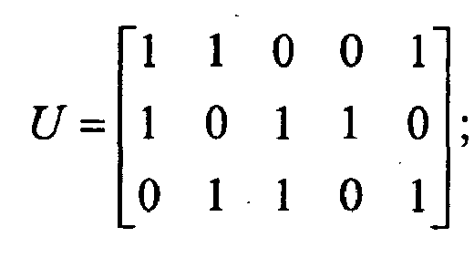
- H be an m ⁇ n parity check matrix for a ( n,k ) LDPC code. Then, H can be rewritten as [ U
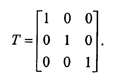
- T ], where U is a m ⁇ k sub-matrix, and T is a m ⁇ (n - k) sub-matrix. H can always be manipulated so that T is quasi-lower-triangular in nature (i.e., its component t i,j is zero whenever i ⁇ j and t i,i 1).
- the second sub-matrix, T is a lower triangular matrix such that each non-zero valued element within the second sub-matrix is situated either along a diagonal of the second sub-matrix, T , or below the diagonal of the second sub-matrix.
- the columns within the sub-matrix, U correspond to encoding the information bits according to a systematic LDPC code
- the columns within the sub-matrix, T correspond to generating the parity (which are sometimes referred to as redundancy or coded bits).
- the diagonal being defined as traversing the second sub-matrix, T, from an upper-left-most element of the second sub-matrix to a lower-right-most element of the second sub-matrix.
- This quasi-lower-triangular nature of the sub-matrix, T allows for the feedback type implementation of a first parity bit to be used in generating a second parity, and so on, during encoding processing.
- x 0 , x 1 ,...., x k -1 be the information bits.
- this encoding processing can be applied to generate a systemic LDPC coded signal, such that after undergoing encoding processing of the information bits, x 0 , x 1 ,..., x k -1 , the resultant codeword also includes those same information bits, x 0 , x 1 ,...., x k-1 , and the parity bits, p 0 , p 1 ,...., p n-k-1 .
- y 0 , y 1 ,.... y n-1 be the current estimated codeword.
- FIG. 4 illustrates an embodiment of combined encoder and syndrome checker 400.
- H low density parity check matrix
- H U
- each non-zero element of the low density parity check matrix, H is represented with a corresponding exclusive-OR (XOR) gate.
- An XOR gate 405 is shown with a corresponding reference numeral, and each of the similar looking elements in the diagram is also an XOR gate.
- There are a number of MUXs whose selection is based upon whether the combined encoder and syndrome checker 400 is performing encoding processing or syndrome checking (as performed during decoding processing). The MUXs are only required to effectuate the processing according to the T sub-matrix of the overall low density parity check matrix, H . This demarcation is shown as the dotted line running vertically in approximately the middle of the diagram.
- a MUX 415 is shown with a corresponding reference numeral, and each of the similar looking elements in the diagram is also a MUX.
- each of the MUXs is connected according to the "0" when the combined encoder and syndrome checker 400 is performing syndrome checking, and each of the MUXs is connected according to the "1" when the combined encoder and syndrome checker 400 is performing encoding.
- the select signal of all the MUXs is set to "0" and each of the inputs, in[0],in[1],...,in[7], is set to y 0 , y 1 ,...., y 7 ; the syndromes s 0 , s 1 , s 2 will then appear on out[0],out[1],out[2].
- the select signal of all the MUXs is set to "1" and each of the inputs, in[0],in[1],in[2],in[3],in[4] is set to x 0 , x 1 , ... , x 4 .
- the parity bits p 0 , p 1 , p 2 will then appear on out[0], out[1], out[2].
- the circuitry of the combined encoder and syndrome checker 400 includes a plurality of XOR (exclusive OR) logic gates, implemented in an array arrangement such that each XOR gate of the plurality of XOR gates corresponds to a non-zero element of the LDPC matrix, and a plurality of MUXs (multiplexors) that is operable to modify the connectivity of a subset of the plurality of XOR gates that corresponds to at least one column of the LDPC matrix that is employed to generate a parity bit during encoding processing.
- XOR exclusive OR
- a select signal is operable to select a first connectivity of each MUX when the circuitry performs encoding of a first information bit to form a first LDPC coded signal, and the select signal is operable to select a second connectivity of each MUX when the circuitry performs decoding processing on a second LDPC coded signal.
- the selection functionality that is performed by the MUXs can be implemented within a variety of ways. For example, other selection functionality can be implemented to effectuate the switching between the encoding and syndrome calculation functionality within the combined encoder and syndrome checker 400.
- FIG. 5 illustrates an alternative embodiment of selecting functionality 500 as employed within the combined encoder and syndrome checker 400 of FIG. 4.
- This selecting functionality 500 as implemented using two MUXs, is shown in the left hand side as being equivalent to that employed within FIG. 4. As can be seen, the same connectivity is achieved in the alternative embodiment depicted on the right hand side.
- FIG. 6 illustrates an embodiment of combined encoder and syndrome checker 600 as implemented for a low density parity check matrix, H, that is quasi-diagonal.
- H [ 1 1 0 0 1 1 0 1 1 0 0 1 1 0 1
- H [ 1 1 0 0 0 1 1 0 1
- a possible implementation of an encoder/syndrome-checker is shown by the combined encoder and syndrome checker 600.
- each of the MUXs is connected according to the "0" when the combined encoder and syndrome checker 600 of FIG. 6 is performing syndrome checking, and each of the MUXs is connected according to the "1" when the combined encoder and syndrome checker 600 of FIG. 6 is performing encoding.
- a reduction in complexity is achieved when the sub-matrix, T , of the low density parity check matrix, H , is diagonal in nature.
- FIG. 7 illustrates an alternative embodiment of selecting functionality 700 as employed within the combined encoder and syndrome checker 600 of FIG. 6.
- This selecting functionality 700 as implemented using two MUXs, is shown in the left hand side as being equivalent to that employed within FIG. 6. As can be seen, the same connectivity is achieved in the alternative embodiment depicted on the right hand side.
- the XOR chains in some of these previous embodiments can be replaced by XOR trees and/or the calculations can be computed in pipeline stages or with time-multiplexing, among other possible variations and embodiments.
- an approach analogous to that which is described herein, within the various embodiments, can be employed so that a syndrome checker can be enhanced to perform encoding as well. This can provides for a reduction in overall size of an actual communication device, which can also provide a savings of overall cost in some instances as well.
- FIG. 8 and FIG. 9 illustrate embodiments of methods that are operable to perform encoding and decoding of LDPC coded signals.
- a method 800 begins by encoding a first information bit using an LDPC (Low Density Parity Check) matrix that includes calculating a parity bit such that the first information bit and the parity bit form at least part of a first LDPC coded signal, as shown in a block 810. Then, the method 800 continues by decoding a second LDPC coded signal, to determine a best estimate of a second information bit encoded within the second LDPC coded signal, that includes performing a syndrome checking calculation, as shown in a block 820. It is noted that the encoding and syndrome checking calculation performed using a shared circuitry, as depicted by reference numeral 830.
- LDPC Low Density Parity Check
- a method 900 begins by receiving a first signal from a communication channel, as shown in a block 910, at substantially the same time that the method 900 performs encoding of a second LDPC coded signal, as shown in a block 912. Then, the method 900 continues by storing the first LDPC coded signal in a memory 920, as shown in a block 920, at substantially the same time that the method 900 performs launching of the second LDPC coded signal into the communication channel, as shown in a block 922. The method 900 then continues by decoding the first LDPC coded signal 930 that has been stored in memory.
- converse type operations could also be performed (e.g., decoding one signal that has been stored in memory while launching another signal into the communication channel, etc.).
- the use of appropriate memory management approaches and methods allows the processing of one signal (i.e., either encoding or decoding), while launching another signal into the communication channel or receiving another signal from the communication channel.
- Other variations can also be performed, borrowing on such memory management approaches, without departing from the scope and spirit of the invention.
Landscapes
- Physics & Mathematics (AREA)
- Probability & Statistics with Applications (AREA)
- Engineering & Computer Science (AREA)
- Theoretical Computer Science (AREA)
- Error Detection And Correction (AREA)
Abstract
Description
- The invention relates generally to communication systems; and, more particularly, it relates to encoding and decoding processing of LDPC (Low Density Parity Check) signals within such communication systems.
- Data communication systems have been under continual development for many years. One such type of communication system that has been of significant interest lately is a communication system that employs iterative error correction codes. Of particular interest is a communication system that employs LDPC (Low Density Parity Check) code. Communications systems with iterative codes are often able to achieve lower bit error rates (BER) than alternative codes for a given signal to noise ratio (SNR).
- A continual and primary directive in this area of development has been to try continually to lower the SNR required to achieve a given BER within a communication system. The ideal goal has been to try to reach Shannon's limit in a communication channel. Shannon's limit may be viewed as being the data rate to be used in a communication channel, having a particular SNR, that achieves error free transmission through the communication channel. In other words, the Shannon limit is the theoretical bound for channel capacity for a given modulation and code rate.
- LDPC code has been shown to provide for excellent decoding performance that can approach the Shannon limit in some cases. For example, some LDPC decoders have been shown to come within 0.3 dB (decibels) from the theoretical Shannon limit. While this example was achieved using an irregular LDPC code of a length of one million, it nevertheless demonstrates the very promising application of LDPC codes within communication systems.
- Generally speaking, within the context of communication systems that employ LDPC codes, there is a first communication device at one end of a communication channel with encoder capability and second communication device at the other end of the communication channel with decoder capability. In many instances, one or both of these two communication devices includes encoder and decoder capability (e.g., within a bi-directional communication system).
- In such prior art communication devices, the requirement to include both encoder and decoder functionality therein can increase the complexity of the communication device. This is sometimes consumptive of real estate which also typically increases overall cost. There is continually a need in the art for more efficient, smaller, and more cost-effective means by which such communication devices can be designed and implemented.
- The present invention is directed to apparatus and methods of operation that are further described in the following Brief Description of the Several Views of the Drawings, the Detailed Description of the Invention, and the claims.
- According to an aspect of the invention, an apparatus comprises:
- a circuitry that is operable to perform both:
- calculation of a parity bit that is generated when encoding a first information bit using an LDPC (Low Density Parity Check) matrix such that the first information bit and the parity bit form at least part of a first LDPC coded signal; and
- syndrome checking calculation during decoding processing of a second LDPC coded signal to determine a best estimate of a second information bit encoded within the second LDPC coded signal.
- Advantageously:
- the circuitry includes a plurality of XOR (exclusive OR) logic gates, implemented in an array arrangement such that each XOR gate of the plurality of XOR gates corresponds to a non-zero element of the LDPC matrix, and a plurality of MUXs (multiplexors) that is operable to modify the connectivity of a subset of the plurality of XOR gates that corresponds to at least one column of the LDPC matrix that is employed to generate the parity bit;
- a select signal is operable to select a first connectivity of each MUX when the circuitry performs encoding of the first information bit to form the first LDPC coded signal; and
- the select signal is operable to select a second connectivity of each MUX when the circuitry performs decoding processing on the second LDPC coded signal.
- Advantageously, the parity bit is a first parity bit;
the first parity bit is provided to a portion of the circuitry that is operable to calculate a second parity bit; and
the first information bit, the first parity bit, and the second parity bit form at least part of the first LDPC coded signal. - Advantageously, the first LDPC coded signal is launched into a communication channel; and the second LDPC coded signal is received from the communication channel.
- Advantageously, the first LDPC coded signal is launched into a communication channel;
the second LDPC coded signal is received from the communication channel; and
the communication channel is a read channel that is coupled to a storage media of a hard disk drive (HDD). - Advantageously, the apparatus further comprises:
- a memory that is operable to:
- store the second LDPC coded signal while encoding the first information bit to form the first LDPC coded signal; and
- store the first LDPC coded signal while performing decoding processing on the second LDPC coded signal.
- Advantageously, the first LDPC coded signal is launched into a communication channel during a first time; and
the second LDPC coded signal is received from the communication channel during a second time; and further comprising: - a memory that is operable to:
- store the second LDPC coded signal while encoding the first information bit to form the first LDPC coded signal; and
- store the first LDPC coded signal while performing decoding processing on the second LDPC coded signal.
- Advantageously, the LDPC matrix corresponds to an LDPC code that is systematic.
- Advantageously, the LDPC matrix can partitioned into a first sub-matrix and a second sub-matrix;
the second sub-matrix includes at least one column of the LDPC matrix that is employed to generate the parity bit;
the second sub-matrix is a lower triangular matrix such that each non-zero valued element within the second sub-matrix is situated either along a diagonal of the second sub-matrix or below the diagonal of the second sub-matrix; and
the diagonal being defined as traversing the second sub-matrix from an upper-left-most element of the second sub-matrix to a lower-right-most element of the second sub-matrix. - Advantageously:
- the circuitry is a first circuitry of the apparatus;
- the apparatus includes the first circuitry and a second circuitry; and
- the apparatus employs both the first circuitry and the second circuitry during decoding processing of the second LDPC coded signal to determine the best estimate of the second information bit encoded within the second LDPC coded signal.
- Advantageously:
- the apparatus is a communication transceiver that is operable to:
- transmit the first LDPC coded signal via a first communication channel; and
- receive the second LDPC coded signal from a second communication channel.
- According to an aspect of the invention, an apparatus comprises:
- an encoder circuitry that is operable to encode a first information bit using an LDPC (Low Density Parity Check) matrix such that the first information bit and the parity bit form at least part of a first LDPC coded signal;
- a decoder circuitry that is operable to employ the LDPC matrix to decode a second LDPC coded signal to determine a best estimate of a second information bit encoded within the second LDPC coded signal; and wherein:
- the encoder circuitry and the decoder circuitry both employ a shared circuitry that is operable to perform both:
- calculation of the parity bit that is generated when encoding the first information bit using the LDPC matrix such that the first information bit and the parity bit form at least part of the first LDPC coded signal; and
- syndrome checking calculation during decoding processing of a second LDPC coded signal to determine a best estimate of a second information bit encoded within the second LDPC coded signal.
- the encoder circuitry and the decoder circuitry both employ a shared circuitry that is operable to perform both:
- Advantageously:
- the decoder circuitry also employs at least one additional circuitry during decoding processing of the second LDPC coded signal to determine the best estimate of the second information bit encoded within the second LDPC coded signal.
- Advantageously:
- the shared circuitry includes a plurality of XOR (exclusive OR) logic gates, implemented in an array arrangement such that each XOR gate of the plurality of XOR gates corresponds to a non-zero element of the LDPC matrix, and a plurality of MUXs (multiplexors) that is operable to modify the connectivity of a subset of the plurality of XOR gates that corresponds to at least one column of the LDPC matrix that is employed to generate the parity bit;
- a select signal is operable to select a first connectivity of each MUX when the circuitry performs encoding of the first information bit to form the first LDPC coded signal; and
- the select signal is operable to select a second connectivity of each MUX when the circuitry performs decoding processing on the second LDPC coded signal.
- Advantageously:
- the parity bit is a first parity bit;
- the first parity bit is provided to a portion of the circuitry that is operable to calculate a second parity bit; and
- the first information bit, the first parity bit, and the second parity bit form at least part of the first LDPC coded signal.
- Advantageously:
- the first LDPC coded signal is launched into a communication channel during a first time; and
- the second LDPC coded signal is received from the communication channel during a second time; and further comprising:
- a memory that is operable to:
- store the second LDPC coded signal while encoding the first information bit to form the first LDPC coded signal; and
- store the first LDPC coded signal while performing decoding processing on the second LDPC coded signal.
- a memory that is operable to:
- According to an aspect of the invention, a method comprises:
- encoding a first information bit using an LDPC (Low Density Parity Check) matrix that includes calculating a parity bit such that the first information bit and the parity bit form at least part of a first LDPC coded signal; and
- decoding a second LDPC coded signal, to determine a best estimate of a second information bit encoded within the second LDPC coded signal, that includes performing a syndrome checking calculation, and wherein:
- the encoding and the syndrome checking calculation being performed using a shared circuitry.
- Advantageously:
- the shared circuitry includes a plurality of XOR (exclusive OR) logic gates, implemented in an array arrangement such that each XOR gate of the plurality of XOR gates corresponds to a non-zero element of the LDPC matrix, and a plurality of MUXs (multiplexors) that is operable to modify the connectivity of a subset of the plurality of XOR gates that corresponds to at least one column of the LDPC matrix that is employed to generate the parity bit; and further comprising:
- selecting a first connectivity of each MUX when the circuitry performs encoding of the first information bit to form the first LDPC coded signal; and
- selecting a second connectivity of each MUX when the circuitry performs decoding processing on the second LDPC coded signal.
- Advantageously, the method further comprises:
- launching the first LDPC coded signal into a communication channel during a first time; and
- receiving the second LDPC coded signal from the communication channel during a second time; and either:
- storing the second LDPC coded signal while encoding the first information bit to form the first LDPC coded signal; or
- storing the first LDPC coded signal while performing decoding processing on the second LDPC coded signal.
- Advantageously:
- the LDPC matrix corresponds to an LDPC code that is systematic;
- the LDPC matrix can partitioned into a first sub-matrix and a second sub-matrix;
- the second sub-matrix includes at least one column of the LDPC matrix that is employed to generate the parity bit;
- the second sub-matrix is a lower triangular matrix such that each non-zero valued element within the second sub-matrix is situated either along a diagonal of the second sub-matrix or below the diagonal of the second sub-matrix; and
- the diagonal being defined as traversing the second sub-matrix from an upper-left-most element of the second sub-matrix to a lower-right-most element of the second sub-matrix.
- Other features and advantages of the present invention will become apparent from the following detailed description of the invention made with reference to the accompanying drawings.
-
- FIG. 1 illustrates an embodiment of a communication system.
- FIG. 2 and FIG. 3 illustrate other various embodiments of communication systems.
- FIG. 4 illustrates an embodiment of combined encoder and syndrome checker.
- FIG. 5 illustrates an alternative embodiment of selecting functionality as employed within the combined encoder and syndrome checker of FIG. 4.
- FIG. 6 illustrates an embodiment of combined encoder and syndrome checker as implemented for a low density parity check matrix, H, that is quasi-diagonal.
- FIG. 7 illustrates an alternative embodiment of selecting functionality as employed within the combined encoder and syndrome checker of FIG. 6.
- FIG. 8 and FIG. 9 illustrate embodiments of methods that are operable to perform encoding and decoding of LDPC coded signals.
- Many communication systems incorporate the use of an LDPC code. While in some applications the encoder and decoder may be in use simultaneously, there are also many applications (e.g., in a hard disk drive (HDD) application) where their operations are mutually exclusive. A novel approach is presented herein which allows a shared circuitry (and/or functional block) to perform both encoding processing as well as the syndrome checking required during decoding processing. In applications in which the encoding and decoding are mutually exclusive operations (i.e., only one is performed at a time), this combined encoder and syndrome checker allows for the construction of a circuitry (and/or functional block) by adding only minimal selection functionality to the syndrome checker of the decoder, thus rendering the encoder virtually costless. In applications in which may need to be performed within a communication system that operates in a duplex manner (i.e., with substantially simultaneous receipt and transmission of signals), a memory can be implemented to allow for memory management of one of the signals while the other is being processed (e.g., within a ping-pong memory configuration or other memory configuration which allows for use of the shared processing resources for a first signal during a first time and use of the shared processing resources for a second signal during a second time).
- The goal of digital communications systems is to transmit digital data from one location, or subsystem, to another either error free or with an acceptably low error rate. As shown in FIG. 1, data may be transmitted over a variety of communications channels in a wide variety of communication systems: magnetic media, wireless, fiber, copper, and other types of media as well.
- FIG. 1 is a diagram illustrating an embodiment of a
communication system 100. - Referring to FIG. 1, this embodiment of a
communication system 100 is acommunication channel 199 that communicatively couples a communication device 110 (including atransmitter 112 having anencoder 114 and including areceiver 116 having a decoder 118) situated at one end of thecommunication channel 199 to another communication device 120 (including atransmitter 126 having anencoder 128 and including areceiver 122 having a decoder 124) at the other end of thecommunication channel 199. In some embodiments, either of thecommunication devices communication channel 199 may be implemented (e.g., asatellite communication channel 130 usingsatellite dishes wireless communication channel 140 usingtowers local antennae wired communication channel 150, and/or a fiber-optic communication channel 160 using electrical to optical (E/O)interface 162 and optical to electrical (O/E) interface 164)). In addition, more than one type of media may be implemented and interfaced together thereby forming thecommunication channel 199. - To reduce transmission errors that may undesirably be incurred within a communication system, error correction and channel coding schemes are often employed. Generally, these error correction and channel coding schemes involve the use of an encoder at the transmitter and a decoder at the receiver.
- FIG. 2 and FIG. 3 illustrate other various embodiments of communication systems.
- Referring to FIG. 2, a
communication system 200 includes acommunication device 210 that is coupled to anotherdevice 290 via acommunication channel 299. Thecommunication device 210 includes both anencoder 220 and adecoder 230. A shared functional block and/or circuitry portion (shown as functional block and/or circuitry 240) that includes both theencoder 220 and asyndrome calculator 232 that is employed during decoding processing by thedecoder 230. It is noted that thedecoder 230 can also include additional circuitry and/or functional blocks as required and/or desired to effectuate the decoding processing of LDPC coded signals thereby, as indicated by the reference numeral 239. - It is also noted that the functional block and/or
circuitry 240 can be implemented strictly as circuitry (e.g., employing certain logic gates such as exclusive-OR (XOR) gates and selection functionality such as with MUXs (multiplexors)). The functional block and/orcircuitry 240 can be implemented strictly in software such as can be employed within a digital signal processor (DSP) or similar type device. Alternatively, the functional block and/orcircuitry 240 can be implemented as a combination of hardware and software as well without departing from the scope and spirit of the invention. - In even other embodiments, the functional block and/or
circuitry 240 can be implemented can be implemented using a shared processing device, individual processing devices, or a plurality of processing devices. Such a processing device may be a microprocessor, micro-controller, digital signal processor, microcomputer, central processing unit, field programmable gate array, programmable logic device, state machine, logic circuitry, analog circuitry, digital circuitry, and/or any device that manipulates signals (analog and/or digital) based on operational instructions. The functional block and/orcircuitry 240 can be coupled to a memory that is operable to store operational instructions that enable to functional block and/orcircuitry 240 to perform the encoding and syndrome calculation processing as required during encoding processing and decoding processing of LDPC coded signals. - Such a memory may be a single memory device or a plurality of memory devices. Such a memory device may be a read-only memory, random access memory, volatile memory, non-volatile memory, static memory, dynamic memory, flash memory, and/or any device that stores digital information. Note that when the functional block and/or
circuitry 240 implements one or more of its functions via a state machine, analog circuitry, digital circuitry, and/or logic circuitry, the memory storing the corresponding operational instructions is embedded with the circuitry comprising the state machine, analog circuitry, digital circuitry, and/or logic circuitry. - The
other device 290 to which thecommunication device 299 is coupled via the communication channel can be anothercommunication device 292, a storage media (e.g., such as within the context of a hard disk drive (HDD)), or any other type of device that is capable to receive or transmit signals. In some embodiments, thecommunication channel 299 is a bi-directional communication channel that is operable to perform transmission of a first signal during a first time and receiving of a second signal during a second time. - Referring to FIG. 3, a
communication system 300 includes acommunication device 310 that is coupled to anotherdevice 390 via acommunication channel 399. Thecommunication device 310 includes both anencoder 320 and adecoder 330. A shared functional block and/or circuitry portion (shown as functional block and/or circuitry 340) that includes both theencoder 320 and asyndrome calculator 332 that is employed during decoding processing by thedecoder 330. It is noted that thedecoder 330 can also include additional circuitry and/or functional blocks as required and/or desired to effectuate the decoding processing of LDPC coded signals thereby, as indicated by thereference numeral 339. - In addition, the
communication device 310 includes amemory 360 that is coupled to each of theencoder 320 anddecoder 330. Thememory 360 is operable to store a first LDPC coded signal while either theencoder 320 performs encoding processing on a second LDPC coded signal or thedecoder 330 performs decoding processing on the second LDPC coded signal. Thememory 360 allows thecommunication device 310 to perform processing (e.g., encoding or decoding) on one LDPC coded signal while another LDPC coded signal is stored in thememory 360. When thecommunication device 310 is coupled to acommunication channel 399 that allows only transmission or receiving at a given time (e.g., such as within a communication channel coupled to a HDD that allows only read or write access at any given time), thememory 360 if operable to assist in the appropriate buffering and memory management of the various LDPC coded signal. - It is also noted that the functional block and/or
circuitry 340 can be implemented strictly as circuitry (e.g., employing certain logic gates such as exclusive-OR (XOR) gates and selection functionality such as with MUXs (multiplexors)). The functional block and/orcircuitry 340 can be implemented strictly in software such as can be employed within a digital signal processor (DSP) or similar type device. Alternatively, the functional block and/orcircuitry 340 can be implemented as a combination of hardware and software as well without departing from the scope and spirit of the invention. - In even other embodiments, the functional block and/or
circuitry 340 can be implemented can be implemented using a shared processing device, individual processing devices, or a plurality of processing devices. Such a processing device may be a microprocessor, micro-controller, digital signal processor, microcomputer, central processing unit, field programmable gate array, programmable logic device, state machine, logic circuitry, analog circuitry, digital circuitry, and/or any device that manipulates signals (analog and/or digital) based on operational instructions. The functional block and/orcircuitry 340 can be coupled to a memory that is operable to store operational instructions that enable to functional block and/orcircuitry 340 to perform the encoding and syndrome calculation processing as required during encoding processing and decoding processing of LDPC coded signals. - Such a memory may be a single memory device or a plurality of memory devices. Such a memory device may be a read-only memory, random access memory, volatile memory, non-volatile memory, static memory, dynamic memory, flash memory, and/or any device that stores digital information. Note that when the functional block and/or
circuitry 340 implements one or more of its functions via a state machine, analog circuitry, digital circuitry, and/or logic circuitry, the memory storing the corresponding operational instructions is embedded with the circuitry comprising the state machine, analog circuitry, digital circuitry, and/or logic circuitry. - In addition, a
selector 350 is also situated in cooperation with thememory 360 such that the storing or retrieving of a first signal to or from thememory 360 does not conflict with the storing or retrieving of a second signal to or from thememory 360. Thisselector 350 also effectuates any connectivity modifications that need to be performed when the functional block and/orcircuitry 340 performs encoding processing vs. decoding processing. - The
other device 390 to which thecommunication device 399 is coupled via the communication channel can be another communication device 392, a storage media (e.g., such as within the context of a HDD), or any other type of device that is capable to receive or transmit signals. In some embodiments, thecommunication channel 399 is a bi-directional communication channel that is operable to perform transmission of a first signal during a first time and receiving of a second signal during a second time. In even other embodiments, thecommunication channel 399 is a bi-directional communication channel that is operable to perform duplex operation (i.e., simultaneous transmission of a first signal and receiving of a second signal during at substantially the same time). - The following description is provided to assist the reader in understanding why and how the encoding and syndrome checking operations can be combined within a functional block and/or circuitry.
- Let H be an m×n parity check matrix for a (n,k) LDPC code. Then, H can be rewritten as [U|T], where U is a m×k sub-matrix, and T is a m×(n-k) sub-matrix. H can always be manipulated so that T is quasi-lower-triangular in nature (i.e., its component t i,j is zero whenever i < j and t i,i = 1). In other words, the second sub-matrix, T, is a lower triangular matrix such that each non-zero valued element within the second sub-matrix is situated either along a diagonal of the second sub-matrix, T, or below the diagonal of the second sub-matrix. It can be seen also that the columns within the sub-matrix, U, correspond to encoding the information bits according to a systematic LDPC code, and the columns within the sub-matrix, T, correspond to generating the parity (which are sometimes referred to as redundancy or coded bits). The diagonal being defined as traversing the second sub-matrix, T, from an upper-left-most element of the second sub-matrix to a lower-right-most element of the second sub-matrix. This quasi-lower-triangular nature of the sub-matrix, T, allows for the feedback type implementation of a first parity bit to be used in generating a second parity, and so on, during encoding processing.
- Let x 0,x 1,....,x k-1 be the information bits. Then, an encoder can compute the parity bits p 0,p 1,...., p n-k-1 using the following formula:

- As can be seen, this encoding processing can be applied to generate a systemic LDPC coded signal, such that after undergoing encoding processing of the information bits, x 0, x 1,...,x k-1, the resultant codeword also includes those same information bits, x 0, x 1,....,x k-1, and the parity bits, p 0,p 1,...., p n-k-1.
- On the other hand, let y 0, y 1,....y n-1 be the current estimated codeword. One of the steps in an iterative LDPC decoder is to check to see if the syndromes s 0, s 1,....,s m-1 are all zero. In other words, based on the current estimate of the codeword, y 0,y 1,....,y n-1, it is determined whether or not the dot product of each row is zero (i.e., whether 0 = Hyt, where y t is the transpose of the current estimate of the codeword, y 0,y 1,....,y n-1). Each syndrome, s i , can be computed by the following formula.

- Note the similarity of the two formulae. For example, if one sets y 0, y 1,....., y k-1 to x 0 ,x 1 ,...,x k-1 and yk , y k+1,.....,y n-1 to all zeros, then s 0 given by the syndrome formula is the same as p 0, the first parity bit generated by the encoder. Subsequently, if all the yi 's remain the same except that yk is set to p 0, then s 1 given by the syndrome formula is the same as p 1. Repeating this argument, it can be shown that all the pi can be generated by the syndrome formula by repeatedly replacing y k+i-1 by p i-1.
- FIG. 4 illustrates an embodiment of combined encoder and
syndrome checker 400. For illustrative purposes, the following low density parity check matrix, H, is considered:
- This low density parity check matrix, H, has the same properties and partitioning as described above as follows:


- As can be seen, each non-zero element of the low density parity check matrix, H, is represented with a corresponding exclusive-OR (XOR) gate. An
XOR gate 405 is shown with a corresponding reference numeral, and each of the similar looking elements in the diagram is also an XOR gate. There are a number of MUXs whose selection is based upon whether the combined encoder andsyndrome checker 400 is performing encoding processing or syndrome checking (as performed during decoding processing). The MUXs are only required to effectuate the processing according to the T sub-matrix of the overall low density parity check matrix, H. This demarcation is shown as the dotted line running vertically in approximately the middle of the diagram. - A
MUX 415 is shown with a corresponding reference numeral, and each of the similar looking elements in the diagram is also a MUX. - It is noted that each of the MUXs is connected according to the "0" when the combined encoder and
syndrome checker 400 is performing syndrome checking, and each of the MUXs is connected according to the "1" when the combined encoder andsyndrome checker 400 is performing encoding. In other words, to use this combined encoder andsyndrome checker 400 to perform the syndrome calculations as required during decoding processing, the select signal of all the MUXs is set to "0" and each of the inputs, in[0],in[1],...,in[7], is set to y 0, y 1,...., y 7; the syndromes s 0, s 1, s 2 will then appear on out[0],out[1],out[2]. - Alternatively, to use this combined encoder and
syndrome checker 400 as an encoder, the select signal of all the MUXs is set to "1" and each of the inputs, in[0],in[1],in[2],in[3],in[4] is set to x 0,x 1,...,x 4 . During encoding processing, the parity bits p 0,p 1,p 2 will then appear on out[0], out[1], out[2]. (NOTE: during encoding, all 8 of the inputs, in[0],in[1],...,in[7], are NOT used as inputs, but only those of in[0],in[1],in[2],in[3],in[4], or corresponding to the sub-matrix, U, are used). - Looking at this functionality another way, the circuitry of the combined encoder and
syndrome checker 400 includes a plurality of XOR (exclusive OR) logic gates, implemented in an array arrangement such that each XOR gate of the plurality of XOR gates corresponds to a non-zero element of the LDPC matrix, and a plurality of MUXs (multiplexors) that is operable to modify the connectivity of a subset of the plurality of XOR gates that corresponds to at least one column of the LDPC matrix that is employed to generate a parity bit during encoding processing. A select signal is operable to select a first connectivity of each MUX when the circuitry performs encoding of a first information bit to form a first LDPC coded signal, and the select signal is operable to select a second connectivity of each MUX when the circuitry performs decoding processing on a second LDPC coded signal. - The selection functionality that is performed by the MUXs can be implemented within a variety of ways. For example, other selection functionality can be implemented to effectuate the switching between the encoding and syndrome calculation functionality within the combined encoder and
syndrome checker 400. - FIG. 5 illustrates an alternative embodiment of selecting
functionality 500 as employed within the combined encoder andsyndrome checker 400 of FIG. 4. This selectingfunctionality 500, as implemented using two MUXs, is shown in the left hand side as being equivalent to that employed within FIG. 4. As can be seen, the same connectivity is achieved in the alternative embodiment depicted on the right hand side. - FIG. 6 illustrates an embodiment of combined encoder and
syndrome checker 600 as implemented for a low density parity check matrix, H, that is quasi-diagonal. - Further simplification is possible if T is quasi-diagonal matrix, i.e., ti,i = 1 and ti,j = 0 whenever i ≠ j and i < k. For example, if

then a possible implementation of an encoder/syndrome-checker is shown by the combined encoder andsyndrome checker 600. - As within [previous embodiments, this quasi-diagonal low density parity check matrix, H, also has the same properties and partitioning as described above as follows:


- As within the embodiment of FIG. 4, each of the MUXs is connected according to the "0" when the combined encoder and
syndrome checker 600 of FIG. 6 is performing syndrome checking, and each of the MUXs is connected according to the "1" when the combined encoder andsyndrome checker 600 of FIG. 6 is performing encoding. A reduction in complexity is achieved when the sub-matrix, T, of the low density parity check matrix, H, is diagonal in nature. - FIG. 7 illustrates an alternative embodiment of selecting
functionality 700 as employed within the combined encoder andsyndrome checker 600 of FIG. 6. This selectingfunctionality 700, as implemented using two MUXs, is shown in the left hand side as being equivalent to that employed within FIG. 6. As can be seen, the same connectivity is achieved in the alternative embodiment depicted on the right hand side. - The configurations depicted in the previous embodiments are merely one possible way in which the connectivity can be implemented. The sharing of hardware for an LDPC encoder and the syndrome checker of its corresponding LDPC decoder can be achieved in many other circuit realizations as well without departing from the scope and spirit of the invention.
- In particular, the XOR chains in some of these previous embodiments can be replaced by XOR trees and/or the calculations can be computed in pipeline stages or with time-multiplexing, among other possible variations and embodiments. In all these cases, an approach analogous to that which is described herein, within the various embodiments, can be employed so that a syndrome checker can be enhanced to perform encoding as well. This can provides for a reduction in overall size of an actual communication device, which can also provide a savings of overall cost in some instances as well.
- FIG. 8 and FIG. 9 illustrate embodiments of methods that are operable to perform encoding and decoding of LDPC coded signals.
- Referring to FIG. 8, a
method 800 begins by encoding a first information bit using an LDPC (Low Density Parity Check) matrix that includes calculating a parity bit such that the first information bit and the parity bit form at least part of a first LDPC coded signal, as shown in a block 810. Then, themethod 800 continues by decoding a second LDPC coded signal, to determine a best estimate of a second information bit encoded within the second LDPC coded signal, that includes performing a syndrome checking calculation, as shown in ablock 820. It is noted that the encoding and syndrome checking calculation performed using a shared circuitry, as depicted by reference numeral 830. - Referring to FIG. 9, a
method 900 begins by receiving a first signal from a communication channel, as shown in ablock 910, at substantially the same time that themethod 900 performs encoding of a second LDPC coded signal, as shown in ablock 912. Then, themethod 900 continues by storing the first LDPC coded signal in amemory 920, as shown in ablock 920, at substantially the same time that themethod 900 performs launching of the second LDPC coded signal into the communication channel, as shown in ablock 922. Themethod 900 then continues by decoding the first LDPC coded signal 930 that has been stored in memory. - It is also noted that converse type operations could also be performed (e.g., decoding one signal that has been stored in memory while launching another signal into the communication channel, etc.). The use of appropriate memory management approaches and methods allows the processing of one signal (i.e., either encoding or decoding), while launching another signal into the communication channel or receiving another signal from the communication channel. Other variations can also be performed, borrowing on such memory management approaches, without departing from the scope and spirit of the invention.
- It is also noted that the methods described within the preceding figures may also be performed within any appropriate system and/or apparatus designs (e.g., communication systems, communication devices, communication transmitters, communication receivers, communication transceivers, and/or functionality described) without departing from the scope and spirit of the invention.
- In view of the above detailed description of the invention and associated drawings, other modifications and variations will now become apparent. It should also be apparent that such other modifications and variations may be effected without departing from the spirit and scope of the invention.
Claims (10)
- An apparatus, comprising:a circuitry that is operable to perform both:calculation of a parity bit that is generated when encoding a first information bit using an LDPC (Low Density Parity Check) matrix such that the first information bit and the parity bit form at least part of a first LDPC coded signal; andsyndrome checking calculation during decoding processing of a second LDPC coded signal to determine a best estimate of a second information bit encoded within the second LDPC coded signal.
- The apparatus of claim 1, wherein:the circuitry includes a plurality of XOR (exclusive OR) logic gates, implemented in an array arrangement such that each XOR gate of the plurality of XOR gates corresponds to a non-zero element of the LDPC matrix, and a plurality of MUXs (multiplexors) that is operable to modify the connectivity of a subset of the plurality of XOR gates that corresponds to at least one column of the LDPC matrix that is employed to generate the parity bit;a select signal is operable to select a first connectivity of each MUX when the circuitry performs encoding of the first information bit to form the first LDPC coded signal; andthe select signal is operable to select a second connectivity of each MUX when the circuitry performs decoding processing on the second LDPC coded signal.
- The apparatus of claim 1, wherein:the parity bit is a first parity bit;the first parity bit is provided to a portion of the circuitry that is operable to calculate a second parity bit; andthe first information bit, the first parity bit, and the second parity bit form at least part of the first LDPC coded signal.
- The apparatus of claim 1, wherein:the first LDPC coded signal is launched into a communication channel; andthe second LDPC coded signal is received from the communication channel.
- The apparatus of claim 1, wherein:the first LDPC coded signal is launched into a communication channel;the second LDPC coded signal is received from the communication channel; andthe communication channel is a read channel that is coupled to a storage media of a hard disk drive (HDD).
- The apparatus of claim 1, further comprising:a memory that is operable to:store the second LDPC coded signal while encoding the first information bit to form the first LDPC coded signal; andstore the first LDPC coded signal while performing decoding processing on the second LDPC coded signal.
- An apparatus, comprising:an encoder circuitry that is operable to encode a first information bit using an LDPC (Low Density Parity Check) matrix such that the first information bit and the parity bit form at least part of a first LDPC coded signal;a decoder circuitry that is operable to employ the LDPC matrix to decode a second LDPC coded signal to determine a best estimate of a second information bit encoded within the second LDPC coded signal; and wherein:the encoder circuitry and the decoder circuitry both employ a shared circuitry that is operable to perform both:calculation of the parity bit that is generated when encoding the first information bit using the LDPC matrix such that the first information bit and the parity bit form at least part of the first LDPC coded signal; andsyndrome checking calculation during decoding processing of a second LDPC coded signal to determine a best estimate of a second information bit encoded within the second LDPC coded signal.
- The apparatus of claim 7, wherein:the decoder circuitry also employs at least one additional circuitry during decoding processing of the second LDPC coded signal to determine the best estimate of the second information bit encoded within the second LDPC coded signal.
- A method, comprising:encoding a first information bit using an LDPC (Low Density Parity Check) matrix that includes calculating a parity bit such that the first information bit and the parity bit form at least part of a first LDPC coded signal; anddecoding a second LDPC coded signal, to determine a best estimate of a second information bit encoded within the second LDPC coded signal, that includes performing a syndrome checking calculation, and wherein:the encoding and the syndrome checking calculation being performed using a shared circuitry.
- The method of claim 9, wherein:the shared circuitry includes a plurality of XOR (exclusive OR) logic gates, implemented in an array arrangement such that each XOR gate of the plurality of XOR gates corresponds to a non-zero element of the LDPC matrix, and a plurality of MUXs (multiplexors) that is operable to modify the connectivity of a subset of the plurality of XOR gates that corresponds to at least one column of the LDPC matrix that is employed to generate the parity bit; and further comprising:selecting a first connectivity of each MUX when the circuitry performs encoding of the first information bit to form the first LDPC coded signal; andselecting a second connectivity of each MUX when the circuitry performs decoding processing on the second LDPC coded signal.
Applications Claiming Priority (1)
| Application Number | Priority Date | Filing Date | Title |
|---|---|---|---|
| US11/493,342 US7752529B2 (en) | 2006-07-26 | 2006-07-26 | Combined LDPC (low density parity check) encoder and syndrome checker |
Publications (3)
| Publication Number | Publication Date |
|---|---|
| EP1883161A2 true EP1883161A2 (en) | 2008-01-30 |
| EP1883161A3 EP1883161A3 (en) | 2008-08-13 |
| EP1883161B1 EP1883161B1 (en) | 2012-09-19 |
Family
ID=38692052
Family Applications (1)
| Application Number | Title | Priority Date | Filing Date |
|---|---|---|---|
| EP07007455A Expired - Fee Related EP1883161B1 (en) | 2006-07-26 | 2007-04-11 | Combined LDPC (low density parity check) encoder and syndrome checker |
Country Status (6)
| Country | Link |
|---|---|
| US (1) | US7752529B2 (en) |
| EP (1) | EP1883161B1 (en) |
| KR (1) | KR100930264B1 (en) |
| CN (1) | CN101114835B (en) |
| HK (1) | HK1117654A1 (en) |
| TW (1) | TWI387210B (en) |
Cited By (1)
| Publication number | Priority date | Publication date | Assignee | Title |
|---|---|---|---|---|
| US8281206B2 (en) | 2008-06-17 | 2012-10-02 | Samsung Electronics Co., Ltd. | Low density parity code encoding device and decoding device and encoding and decoding methods thereof |
Families Citing this family (8)
| Publication number | Priority date | Publication date | Assignee | Title |
|---|---|---|---|---|
| FR2927206B1 (en) * | 2008-02-04 | 2014-02-14 | Groupe Des Ecoles De Telecommunications Get Ecole Nationale Superieure Des Telecommunications Enst | METHOD OF DECODING A SIGNAL TRANSMITTED IN A MULTI-ANTENNA SYSTEM, COMPUTER PROGRAM PRODUCT AND CORRESPONDING DECODING DEVICE |
| US8739001B2 (en) * | 2011-04-23 | 2014-05-27 | Analogies Sa | LDPC encoding and decoding techniques |
| EP2525497A1 (en) | 2011-05-18 | 2012-11-21 | Panasonic Corporation | Bit-interleaved coding and modulation (BICM) with quasi-cyclic LDPC codes |
| WO2013024789A1 (en) | 2011-08-12 | 2013-02-21 | 株式会社 Trigence Semiconductor | Drive circuit |
| US9081992B2 (en) | 2011-09-16 | 2015-07-14 | The Intervention Science Fund I, LLC | Confirming that an image includes at least a portion of a target region of interest |
| US20160049962A1 (en) * | 2013-04-25 | 2016-02-18 | LI, Jian | Method and apparatus of ldpc encoder in 10gbase-t system |
| US10193574B1 (en) * | 2016-05-19 | 2019-01-29 | Apple Inc. | Efficient syndrome calculation in processing a GLDPC code |
| CN117331742A (en) * | 2022-06-23 | 2024-01-02 | 慧荣科技股份有限公司 | Apparatus and method for generating low density parity check code |
Citations (1)
| Publication number | Priority date | Publication date | Assignee | Title |
|---|---|---|---|---|
| US20050283707A1 (en) * | 2004-06-22 | 2005-12-22 | Eran Sharon | LDPC decoder for decoding a low-density parity check (LDPC) codewords |
Family Cites Families (14)
| Publication number | Priority date | Publication date | Assignee | Title |
|---|---|---|---|---|
| US3542756A (en) | 1968-02-07 | 1970-11-24 | Codex Corp | Error correcting |
| US3665396A (en) | 1968-10-11 | 1972-05-23 | Codex Corp | Sequential decoding |
| US4295218A (en) | 1979-06-25 | 1981-10-13 | Regents Of The University Of California | Error-correcting coding system |
| US6430233B1 (en) | 1999-08-30 | 2002-08-06 | Hughes Electronics Corporation | Single-LNB satellite data receiver |
| US6473010B1 (en) | 2000-04-04 | 2002-10-29 | Marvell International, Ltd. | Method and apparatus for determining error correction code failure rate for iterative decoding algorithms |
| US20020051501A1 (en) * | 2000-04-28 | 2002-05-02 | Victor Demjanenko | Use of turbo-like codes for QAM modulation using independent I and Q decoding techniques and applications to xDSL systems |
| US6567465B2 (en) | 2001-05-21 | 2003-05-20 | Pc Tel Inc. | DSL modem utilizing low density parity check codes |
| US6633856B2 (en) * | 2001-06-15 | 2003-10-14 | Flarion Technologies, Inc. | Methods and apparatus for decoding LDPC codes |
| US6789227B2 (en) * | 2001-07-05 | 2004-09-07 | International Business Machines Corporation | System and method for generating low density parity check codes using bit-filling |
| US6895547B2 (en) * | 2001-07-11 | 2005-05-17 | International Business Machines Corporation | Method and apparatus for low density parity check encoding of data |
| US7246304B2 (en) | 2001-09-01 | 2007-07-17 | Dsp Group Inc | Decoding architecture for low density parity check codes |
| US7073114B2 (en) * | 2002-06-24 | 2006-07-04 | Massey Peter C | Method of decoding utilizing a recursive table-lookup decoding method |
| US7409628B2 (en) | 2002-08-15 | 2008-08-05 | Broadcom Corporation | Efficient design to implement LDPC (Low Density Parity Check) decoder |
| KR20040101743A (en) | 2003-05-26 | 2004-12-03 | 삼성전자주식회사 | Apparatus and method for decoding of ldpc in a communication system |
-
2006
- 2006-07-26 US US11/493,342 patent/US7752529B2/en not_active Expired - Fee Related
-
2007
- 2007-04-11 EP EP07007455A patent/EP1883161B1/en not_active Expired - Fee Related
- 2007-07-25 TW TW096127124A patent/TWI387210B/en not_active IP Right Cessation
- 2007-07-25 CN CN2007101384691A patent/CN101114835B/en not_active Expired - Fee Related
- 2007-07-26 KR KR1020070075246A patent/KR100930264B1/en not_active IP Right Cessation
-
2008
- 2008-07-15 HK HK08107788.3A patent/HK1117654A1/en unknown
Patent Citations (1)
| Publication number | Priority date | Publication date | Assignee | Title |
|---|---|---|---|---|
| US20050283707A1 (en) * | 2004-06-22 | 2005-12-22 | Eran Sharon | LDPC decoder for decoding a low-density parity check (LDPC) codewords |
Non-Patent Citations (1)
| Title |
|---|
| HALEY D ET AL: "Iterative encoding of low-density parity-check codes" GLOBECOM'02. 2002 - IEEE GLOBAL TELECOMMUNICATIONS CONFERENCE. CONFERENCE PROCEEDINGS. TAIPEI, TAIWAN, NOV. 17 - 21, 2002; [IEEE GLOBAL TELECOMMUNICATIONS CONFERENCE], NEW YORK, NY : IEEE, US, vol. 2, 17 November 2002 (2002-11-17), pages 1289-1293, XP010636353 ISBN: 978-0-7803-7632-8 * |
Cited By (1)
| Publication number | Priority date | Publication date | Assignee | Title |
|---|---|---|---|---|
| US8281206B2 (en) | 2008-06-17 | 2012-10-02 | Samsung Electronics Co., Ltd. | Low density parity code encoding device and decoding device and encoding and decoding methods thereof |
Also Published As
| Publication number | Publication date |
|---|---|
| HK1117654A1 (en) | 2009-01-16 |
| KR100930264B1 (en) | 2009-12-09 |
| US7752529B2 (en) | 2010-07-06 |
| US20080052593A1 (en) | 2008-02-28 |
| EP1883161B1 (en) | 2012-09-19 |
| CN101114835A (en) | 2008-01-30 |
| TWI387210B (en) | 2013-02-21 |
| CN101114835B (en) | 2010-07-14 |
| TW200826513A (en) | 2008-06-16 |
| KR20080010355A (en) | 2008-01-30 |
| EP1883161A3 (en) | 2008-08-13 |
Similar Documents
| Publication | Publication Date | Title |
|---|---|---|
| US7752529B2 (en) | Combined LDPC (low density parity check) encoder and syndrome checker | |
| US8341492B2 (en) | Quasi-cyclic LDPC (low density parity check) code construction | |
| US8966336B2 (en) | Selective merge and partial reuse LDPC (low density parity check) code construction for limited number of layers belief propagation (BP) decoding | |
| US8473817B2 (en) | LDPC (low density parity check) code size adjustment by shortening and puncturing | |
| US8438459B2 (en) | Apparatus and method for decoding using channel code | |
| US8276055B1 (en) | Low latency programmable encoder with outer systematic code and low-density parity-check code | |
| US8386906B2 (en) | Multi-CSI (cyclic shifted identity) sub-matrix based LDPC (low density parity check) codes | |
| US8930793B2 (en) | Method of communicating signal data in GNSS using LDPC convolution codes and a system thereof | |
| US8880976B2 (en) | Method and apparatus for encoding LBA information into the parity of a LDPC system | |
| US20120311400A1 (en) | Single CRC polynomial for both turbo code block CRC and transport block CRC | |
| CN103888148A (en) | LDPC hard decision decoding method for dynamic threshold value bit-flipping | |
| US20080294963A1 (en) | Method and apparatus for designing low density parity check code with multiple code rates, and information storage medium thereof | |
| US9048873B2 (en) | Systems and methods for multi-stage encoding of concatenated low density parity check codes | |
| US20110029835A1 (en) | Systems and Methods for Quasi-Cyclic LDPC Code Production and Decoding | |
| CN102835032A (en) | Quasi-cyclic ldpc encoding and decoding for non-integer multiples of circulant size | |
| KR102221430B1 (en) | Polar encoding and decoding method, transmitting device, and receiving device | |
| JP5215537B2 (en) | Information encoding apparatus, information decoding apparatus, information encoding method, and information decoding method | |
| US8086930B2 (en) | Fixed-spacing parity insertion for FEC (Forward Error Correction) codewords | |
| US20100185913A1 (en) | Method for decoding ldpc code and the circuit thereof | |
| US20080243974A1 (en) | Electronic data shift device, in particular for coding/decoding with an ldpc code | |
| US7181677B1 (en) | System and method for producing data and ECC code words using a high rate restricted-symbol code | |
| US20180091174A1 (en) | Progressive polar channel coding in flash memory and communications | |
| US8612826B2 (en) | Systems and methods for non-binary LDPC encoding | |
| KR100682243B1 (en) | Method for encoding and decoding error correction of volumetric reed-solomon product code | |
| KR20060013197A (en) | Encoding method by using ldpc code and computer-readable medium for the same |
Legal Events
| Date | Code | Title | Description |
|---|---|---|---|
| PUAI | Public reference made under article 153(3) epc to a published international application that has entered the european phase |
Free format text: ORIGINAL CODE: 0009012 |
|
| AK | Designated contracting states |
Kind code of ref document: A2 Designated state(s): AT BE BG CH CY CZ DE DK EE ES FI FR GB GR HU IE IS IT LI LT LU LV MC MT NL PL PT RO SE SI SK TR |
|
| AX | Request for extension of the european patent |
Extension state: AL BA HR MK YU |
|
| PUAL | Search report despatched |
Free format text: ORIGINAL CODE: 0009013 |
|
| AK | Designated contracting states |
Kind code of ref document: A3 Designated state(s): AT BE BG CH CY CZ DE DK EE ES FI FR GB GR HU IE IS IT LI LT LU LV MC MT NL PL PT RO SE SI SK TR |
|
| AX | Request for extension of the european patent |
Extension state: AL BA HR MK RS |
|
| 17P | Request for examination filed |
Effective date: 20090213 |
|
| 17Q | First examination report despatched |
Effective date: 20090312 |
|
| AKX | Designation fees paid |
Designated state(s): DE FR GB |
|
| GRAP | Despatch of communication of intention to grant a patent |
Free format text: ORIGINAL CODE: EPIDOSNIGR1 |
|
| GRAS | Grant fee paid |
Free format text: ORIGINAL CODE: EPIDOSNIGR3 |
|
| GRAA | (expected) grant |
Free format text: ORIGINAL CODE: 0009210 |
|
| AK | Designated contracting states |
Kind code of ref document: B1 Designated state(s): DE FR GB |
|
| REG | Reference to a national code |
Ref country code: GB Ref legal event code: FG4D |
|
| REG | Reference to a national code |
Ref country code: DE Ref legal event code: R096 Ref document number: 602007025522 Country of ref document: DE Effective date: 20121108 |
|
| PLBE | No opposition filed within time limit |
Free format text: ORIGINAL CODE: 0009261 |
|
| STAA | Information on the status of an ep patent application or granted ep patent |
Free format text: STATUS: NO OPPOSITION FILED WITHIN TIME LIMIT |
|
| PGFP | Annual fee paid to national office [announced via postgrant information from national office to epo] |
Ref country code: GB Payment date: 20130422 Year of fee payment: 7 |
|
| 26N | No opposition filed |
Effective date: 20130620 |
|
| PGFP | Annual fee paid to national office [announced via postgrant information from national office to epo] |
Ref country code: FR Payment date: 20130523 Year of fee payment: 7 |
|
| REG | Reference to a national code |
Ref country code: DE Ref legal event code: R097 Ref document number: 602007025522 Country of ref document: DE Effective date: 20130620 |
|
| PGFP | Annual fee paid to national office [announced via postgrant information from national office to epo] |
Ref country code: DE Payment date: 20140430 Year of fee payment: 8 |
|
| REG | Reference to a national code |
Ref country code: DE Ref legal event code: R119 Ref document number: 602007025522 Country of ref document: DE |
|
| GBPC | Gb: european patent ceased through non-payment of renewal fee |
Effective date: 20140411 |
|
| REG | Reference to a national code |
Ref country code: FR Ref legal event code: ST Effective date: 20141231 |
|
| REG | Reference to a national code |
Ref country code: DE Ref legal event code: R119 Ref document number: 602007025522 Country of ref document: DE Effective date: 20141101 |
|
| PG25 | Lapsed in a contracting state [announced via postgrant information from national office to epo] |
Ref country code: DE Free format text: LAPSE BECAUSE OF NON-PAYMENT OF DUE FEES Effective date: 20141101 Ref country code: GB Free format text: LAPSE BECAUSE OF NON-PAYMENT OF DUE FEES Effective date: 20140411 |
|
| PG25 | Lapsed in a contracting state [announced via postgrant information from national office to epo] |
Ref country code: FR Free format text: LAPSE BECAUSE OF NON-PAYMENT OF DUE FEES Effective date: 20140430 |