EP1883158A1 - Elastic boundary wave device - Google Patents
Elastic boundary wave device Download PDFInfo
- Publication number
- EP1883158A1 EP1883158A1 EP06732553A EP06732553A EP1883158A1 EP 1883158 A1 EP1883158 A1 EP 1883158A1 EP 06732553 A EP06732553 A EP 06732553A EP 06732553 A EP06732553 A EP 06732553A EP 1883158 A1 EP1883158 A1 EP 1883158A1
- Authority
- EP
- European Patent Office
- Prior art keywords
- medium
- conductor layer
- boundary wave
- elastic boundary
- idt
- Prior art date
- Legal status (The legal status is an assumption and is not a legal conclusion. Google has not performed a legal analysis and makes no representation as to the accuracy of the status listed.)
- Withdrawn
Links
Images


Classifications
-
- H—ELECTRICITY
- H03—ELECTRONIC CIRCUITRY
- H03H—IMPEDANCE NETWORKS, e.g. RESONANT CIRCUITS; RESONATORS
- H03H9/00—Networks comprising electromechanical or electro-acoustic devices; Electromechanical resonators
- H03H9/02—Details
- H03H9/02535—Details of surface acoustic wave devices
- H03H9/02818—Means for compensation or elimination of undesirable effects
- H03H9/02834—Means for compensation or elimination of undesirable effects of temperature influence
-
- H—ELECTRICITY
- H03—ELECTRONIC CIRCUITRY
- H03H—IMPEDANCE NETWORKS, e.g. RESONANT CIRCUITS; RESONATORS
- H03H9/00—Networks comprising electromechanical or electro-acoustic devices; Electromechanical resonators
- H03H9/02—Details
- H03H9/125—Driving means, e.g. electrodes, coils
- H03H9/145—Driving means, e.g. electrodes, coils for networks using surface acoustic waves
-
- H—ELECTRICITY
- H03—ELECTRONIC CIRCUITRY
- H03H—IMPEDANCE NETWORKS, e.g. RESONANT CIRCUITS; RESONATORS
- H03H9/00—Networks comprising electromechanical or electro-acoustic devices; Electromechanical resonators
- H03H9/02—Details
- H03H9/0222—Details of interface-acoustic, boundary, pseudo-acoustic or Stonely wave devices
-
- H—ELECTRICITY
- H03—ELECTRONIC CIRCUITRY
- H03H—IMPEDANCE NETWORKS, e.g. RESONANT CIRCUITS; RESONATORS
- H03H9/00—Networks comprising electromechanical or electro-acoustic devices; Electromechanical resonators
- H03H9/02—Details
- H03H9/02535—Details of surface acoustic wave devices
- H03H9/02818—Means for compensation or elimination of undesirable effects
- H03H9/02944—Means for compensation or elimination of undesirable effects of ohmic loss
-
- H—ELECTRICITY
- H03—ELECTRONIC CIRCUITRY
- H03H—IMPEDANCE NETWORKS, e.g. RESONANT CIRCUITS; RESONATORS
- H03H9/00—Networks comprising electromechanical or electro-acoustic devices; Electromechanical resonators
- H03H9/02—Details
- H03H9/125—Driving means, e.g. electrodes, coils
- H03H9/145—Driving means, e.g. electrodes, coils for networks using surface acoustic waves
- H03H9/14517—Means for weighting
- H03H9/14529—Distributed tap
- H03H9/14532—Series weighting; Transverse weighting
-
- H—ELECTRICITY
- H03—ELECTRONIC CIRCUITRY
- H03H—IMPEDANCE NETWORKS, e.g. RESONANT CIRCUITS; RESONATORS
- H03H9/00—Networks comprising electromechanical or electro-acoustic devices; Electromechanical resonators
- H03H9/02—Details
- H03H9/125—Driving means, e.g. electrodes, coils
- H03H9/145—Driving means, e.g. electrodes, coils for networks using surface acoustic waves
- H03H9/14538—Formation
- H03H9/14541—Multilayer finger or busbar electrode
Definitions
- the present invention relates to an elastic boundary wave device for use in a resonator, a band-pass filter, or the like, and more particularly to an elastic boundary wave device including an IDT disposed between a first medium and a second medium.
- the first medium and the second medium are formed of different materials.
- An elastic boundary wave device has a structure in which interdigital electrodes (IDTs) are disposed on an interface between different media.
- IDTs interdigital electrodes
- An elastic boundary wave propagates through a layered body of the different media in the elastic boundary wave device.
- the elastic boundary wave device can therefore omit a complicated package structure and have a simpler and lower-profile structure than surface acoustic wave devices.
- An elastic boundary wave device that operates at a higher frequency has a shorter period of IDT. This decreases the width of electrode fingers of an IDT or a reflector, thus increasing the conductor resistance and the loss of the electrode fingers.
- an elastic boundary wave device when the sonic velocity of an elastic boundary wave is smaller than the sonic velocity of a transverse wave propagating through the media disposed over and under the interface, the elastic boundary wave can be confined between the upper medium and the lower medium. This can reduce the propagation loss.
- Patent Document 1 Japanese Unexamined Patent Application Publication No. 58-30217
- Patent Document 2 DE 4132309 A1
- Fi V/ ⁇ i (equation (a)
- ⁇ i the period of IDT.
- a first invention provides an elastic boundary wave device that includes a first medium having a positive temperature coefficient of delay in a propagation direction of an elastic boundary wave; a second medium having a negative temperature coefficient of delay in a propagation direction of an elastic boundary wave; and an IDT including laminated conductor layers disposed between the first medium and the second medium, wherein the lamination direction of the first medium and the second medium is the thickness direction of the IDT, a plane that halves the IDT in the thickness direction is taken as an interface, the energy of an elastic boundary wave present on the first medium side of the interface is denoted as E1, and the energy of an elastic boundary wave present on the second medium side of the interface is denoted as E2, and wherein if the IDT were composed only of a conductor layer having the highest density among the laminated conductor layers of the IDT, when the energy of an elastic boundary wave present on the first medium side of the interface is denoted as E1' and the energy of an elastic boundary wave present on the second medium side of the interface is denoted as E2', the
- the IDT has a layered structure composed of a first conductor layer formed of a metal having a density in the range of 7000 to 22000 kg/m 3 and a second conductor layer formed of a metal having a density of at least 1740 kg/m 3 and less than 11000 kg/m 3 , the density ⁇ 1 of the first conductor layer and the density ⁇ 2 of the second conductor layer satisfy the relationship of ⁇ 1/ ⁇ 2 > 1.8, and a conductor layer disposed on the second medium side of the IDT is the first conductor layer.
- the thickness H of the first conductor layer and the electrode finger period ⁇ of the IDT satisfy the relationship of 0.034 ⁇ ⁇ H ⁇ 0.5 ⁇ .
- an adherent layer is disposed at a portion at which the IDT is in contact with the first medium and/or the second medium.
- a second invention provides an elastic boundary wave device that includes a first medium having a positive temperature coefficient of delay in a propagation direction of an elastic boundary wave; a second medium having a negative temperature coefficient of delay in a propagation direction of an elastic boundary wave; and an IDT disposed between the first medium and the second medium, wherein the IDT has a layered structure composed of a first conductor layer formed of a metal having a density in the range of 7000 to 22000 kg/m 3 and a second conductor layer formed of a metal having a density of at least 1740 kg/m 3 and less than 11000 kg/m 3 , the density ⁇ 1 of the first conductor layer and the density ⁇ 2 of the second conductor layer satisfy the relationship of ⁇ 1/ ⁇ 2 > 1.8, a conductor layer disposed on the second medium side of the IDT is the first conductor layer, and the thickness H of the first conductor layer and the electrode finger pitch ⁇ of the IDT satisfy the relationship of 0.034 ⁇ ⁇ H ⁇ 0.5 ⁇ .
- an adherent layer is disposed at a portion at which the IDT is in contact with the first medium and/or the second medium.
- the first medium is composed of one material selected from the group consisting of LiTaO 3 LiNbO 3 quartz crystal, PZT, LBO, langasite, langanite, and glass.
- the second medium is composed of at least one material selected from the group consisting of SiO 2 , quartz crystal, LBO, langasite, langanite, and glass. This material is different from the material used for the first medium.
- the metal constituting the first conductor layer is a metal selected from the group consisting of Pt, Au, Cu, Ag, Ni, Fe, W, Ta, Cr, and an alloy based thereon
- the metal constituting the second conductor layer is a metal selected from the group consisting of Mg, Al, Ti, and an alloy based thereon.
- the metal constituting the first conductor layer is Au
- the metal constituting the second conductor layer is a metal selected from the group consisting of Al, Mg, Ti, Cr, Ni, Cu, Ag, and an alloy based thereon.
- the metal constituting the first conductor layer is Cu
- the metal constituting the second conductor layer is a metal selected from the group consisting of Al, Mg, Ti, and an alloy based thereon.
- the film thickness of the IDT is preferably 0.3 ⁇ or less.
- the elastic boundary wave device further includes a reflector disposed between the first medium and the second medium.
- the reflector is formed of the same electrode material as the IDT.
- the IDT formed of a plurality of conductor layers is disposed between the first medium having a positive temperature coefficient of delay TCD in a propagation direction of an elastic boundary wave and the second medium having a negative TCD in a propagation direction of an elastic boundary wave, and the relationship of E1/E2 ⁇ E1'/E2' is satisfied.
- the energy of an elastic boundary wave is higher on the second medium side than on the first medium side, since the temperature coefficient of delay TCD of the second medium is negative, for example, the placement of a high-density conductor layer on the second medium side can sufficiently decrease the TCD.
- an elastic boundary wave device having a sufficiently small TCD can easily be provide by placing a first metal layer formed of a higher-density metal on the second medium side.
- the IDT when the IDT has the layered structure composed of the first conductor layer formed of a metal having a density in the range of 7000 to 22000 kg/m 3 and the second conductor layer formed of a metal having a density of at least 1740 kg/m 3 and less than 11000 kg/m 3 , when the density ⁇ 1 of the first conductor layer and the density ⁇ 2 of the second conductor layer satisfy the relationship of ⁇ 1/ ⁇ 2 > 1.8, and when a conductor layer disposed on the second medium side of the IDT is the first conductor layer, a high-density conductor layer is disposed on the second medium side. This can effectively reduce the TCD.
- the TCD when the relationship of 0.034 ⁇ ⁇ H ⁇ 0.5 ⁇ is satisfied, the TCD can further be reduced.
- the IDT can effectively enhance the adhesiveness between the IDT and the first medium and/or the second medium.
- the IDT is disposed between the first medium having a positive TCD and the second medium having a negative TCD, the IDT has a layered structure including the first conductor layer and the second conductor layer, and the first conductor layer is disposed on the second medium side.
- the TCD can sufficiently be reduced.
- the TCD can further be reduced.
- the IDT can effectively enhance the adhesiveness between the IDT and the first medium and/or the second medium.
- the TCD can be positive under a certain condition.
- use of a medium having a negative TCD as the second medium can reduce the TCD of the whole elastic boundary wave device.
- the TCD can be negative under a certain condition.
- use of a medium having a positive TCD as the first medium can reduce the TCD of the whole elastic boundary wave device.
- the TCD can further be reduced by increasing the vibrational energy of an elastic boundary wave occurring in the second medium.
- the metals constituting the first conductor layer and the second conductor layer may be any metals.
- the metal constituting the first conductor layer is a metal selected from the group consisting of Pt, Au, Cu, Ag, Ni, Fe, W, Ta, Cr, and an alloy based thereon
- the metal constituting the second conductor layer is a metal selected from the group consisting of Mg, Al, Ti, Cr, Ni, Cu, Ag, and an alloy based thereon
- the first conductor layer and the second conductor layer can easily be formed with these widely-used metals.
- the metal constituting the first conductor layer is Au
- the metal constituting the second conductor layer is a metal selected from the group consisting of Al, Mg, Ti, Cr, Ni, Cu, Ag, and an alloy based thereon, excellent characteristics like the absolute value of the temperature coefficient of frequency TCD as small as 10 ppm/°C or less can easily be achieved.
- the metal constituting the first conductor layer is Cu
- a metal selected from the group consisting of Al, Mg, Ti, and an alloy based thereon is preferably used as the metal constituting the second conductor layer, because this can satisfy the relationship of ⁇ 1/ ⁇ 2 > 1.8 and thereby reduce the absolute value of TCD.
- the film thickness of the IDT is preferably 0.3 ⁇ , or less. This can easily reduce the absolute value of TCD to 10 ppm/°C or less.
- an elastic boundary wave resonator or an elastic boundary wave resonator filter each including the reflector can easily be produced according to the present invention.
- the density of SiO 2 is 2210 kg/m 3
- the acoustic characteristic impedance of a transverse wave of SiO 2 is 8.3 x 10 6 kg.s/m 2
- the density of Al is 2699 kg/m 3
- the acoustic characteristic impedance of a transverse wave of Al is 8.4 x 10 6 kg.s/m 2
- the density of Cu is 8939 kg/m 3
- the acoustic characteristic impedance of a transverse wave of Cu is 21.4 x 10 6 kg.s/m 2
- the density of Ag is 10500 kg/m 3
- the acoustic characteristic impedance of a transverse wave of Ag is 18.6 ⁇ 10 6 kg ⁇ s/m 2
- the density of Au is 19300 kg/m 3
- the acoustic characteristic impedance of a transverse wave of Au is 24.0 ⁇ 10 6 kg.s/m 2 .
- the Euler angles ( ⁇ , ⁇ , ⁇ ) that represent a cutting plane of a substrate and the iron plate direction of a boundary wave in the present specification are right-handed Euler angles described in a document of " Danseihasosi gijyutu handobukku (handbook of acoustic wave device technology)" (Japan Society for the Promotion of Science, 150th committee on the acoustic wave device technology, the first impression of the first edition, issued on November 30, 1991, p. 549 ).
- the X-axis is rotated counterclockwise ⁇ turns about the Z-axis to provide an Xa-axis.
- the Z-axis is rotated counterclockwise ⁇ turns about the Xa-axis to provide a Z' axis.
- a plane including the Xa-axis and being normal to the Z'-axis is taken as a cutting plane of a substrate.
- the Xa-axis is rotated counterclockwise ⁇ turns about the Z'-axis to provide an X' axis.
- the direction of the X' axis is taken as a propagation direction of a boundary wave.
- the Z-axis is parallel to the c-axis
- the X-axis is any one of three equivalent a-axes
- the Y-axis is normal to a plane containing the X-axis and the Z-axis.
- the Euler angles ( ⁇ , ⁇ , ⁇ ) of LiNbO 3 in the present invention may be crystallographically equivalent.
- LiNbO 3 is a crystal of trigonal 3m point group.
- the propagation characteristics of a boundary wave having Euler angles of (30°, ⁇ , ⁇ ) are equivalent to the propagation characteristics of a boundary wave having Euler angles of (90°, 180° - ⁇ , 180° - ⁇ ).
- the propagation characteristics of a boundary wave having Euler angles of (30°, 90°, 45°) is equivalent to the propagation characteristics of a boundary wave having the Euler angles described in the table.
- the material constants for a conductor used for calculation in the present invention are the material constants for a polycrystal. Even in a crystal, such as an epitaxial film, the crystal orientation dependence of a substrate predominates over the crystal orientation dependence of a film in the boundary wave characteristics. Hence, the equation [4] can also provide the propagation characteristics of a boundary wave in a crystal without causing a practical problem.
- Figs. 1 and 2 are a schematic cross-sectional plan view and a schematic cross-sectional front view of an elastic boundary wave device according to one embodiment of the present invention.
- An elastic boundary wave device 10 includes a laminated body composed of a first medium 11 and a second medium 12.
- the first medium 11 in the present embodiment is a 15° rotated Y-cut X-propagation (Euler angles (0°, 105°, 0°)) LiNbO 3 plate, which serves as a piezoelectric substance.
- the second medium 12 in the present embodiment is formed of SiO 2 which serves as a nonconductive substance.
- An IDT 13 and reflectors 14 and 15 are disposed on an interface between the first medium 11 and the second medium 12.
- a plurality of electrode fingers 13a and a plurality of electrode fingers 13b intercalate between each other.
- the plurality of electrode fingers 13a is electrically connected to one bus bar.
- the plurality of electrode fingers 13b is electrically connected to the other bus bar.
- the IDT 13 and the reflectors 14 and 15 in the present embodiment have a layered structure including a first conductor layer formed of Au and having a higher density and a second conductor layer formed of Al and having a lower density.
- Fig. 3 is a schematic enlarged cross-sectional view illustrating the cross-sectional structure of the electrode fingers 13a and 13b.
- a first conductor layer 16 and a second conductor layer 17 are stacked.
- the first conductor layer 16 formed of Au is disposed on the side of the second medium 12 formed of a nonconductive substance.
- the second conductor layer 17 formed of Al is disposed on the side of the first medium 11, which serves as a piezoelectric substance.
- the reflectors 14 and 15 also have the same electrode structure as that of the IDT 13. Thus, in the reflectors 14 and 15, the first conductor layer 16 and the second conductor layer 17 are also stacked.
- the first medium 11 and the second medium 12 are formed as described above, and the IDT 13 and the reflectors 14 and 15 have the electrode structure described above.
- a plane that halves the IDT 13 in the thickness direction is taken as an interface.
- the energy of an elastic boundary wave present on the side of the first medium 11 of the interface is denoted as E1.
- the energy of an elastic boundary wave present on the second medium side of the interface is denoted as E2.
- the IDT 13 were formed only of a single conductor Au, which constitutes the first conductor layer having the highest density among the laminated conductor layers 16 and 17 of the IDT 13, when the energy of an elastic boundary wave present on the first medium side of the interface is denoted as E1' and the energy of an elastic boundary wave present on the side of the second medium 12 of the interface is denoted as E2', the energies of an elastic boundary wave would satisfy the relationship of E1/E2 ⁇ E1'/E2' so that the sonic velocity of an elastic boundary wave in the IDT 13 composed of the laminated conductor layers 16 and 17 is equal to the sonic velocity of an elastic boundary wave if the IDT 13 were formed only of Au. This relationship allows the elastic boundary wave device 10 to have a smaller TCD as a whole. This is specifically described below.
- the second conductor layer 17 formed of Al is disposed on the side of the first medium 11, which serves as a piezoelectric substance.
- the first conductor layer 16 formed of Au is disposed on the side of SiO 2 , which is a second medium.
- the sonic velocity of an elastic boundary wave, the electromechanical coupling coefficient K 2 , and the temperature coefficient of delay TCD were determined as a function of the thickness of a conductor layer. The conditions are described below.
- a 15° rotated Y-cut X-propagation LiNbO 3 substrate was used as LiNbO 3 .
- the thickness of Au constituting the first conductor layer 16 was 0.05 ⁇ or variable.
- the thickness of the second conductor layer 17 formed of Al was 0.1 ⁇ or variable.
- the first medium 11 and the second medium 12 had an infinite thickness.
- the sonic velocity was determined on the assumption that the normal components of the displacement, of the electric potential, of the electric flux, and of the density and the vertical stress were continuous at the boundary between the first medium 11 and the second medium, the boundary between the first medium 11 and the IDT 13, and the boundary between the IDT 13 and the second medium 12; the first medium 11 and the second medium 12 had an infinite thickness; and conductors constituting the IDT and other components had a relative dielectric constant of 1.
- the sonic velocity was determined on the assumption that the electric potential was zero at the boundary between the second medium and the IDT and the boundary between the IDT and the first medium.
- the electromechanical coupling coefficient K 2 was determined by the equation (1).
- Vf denotes the sonic velocity at the open boundary.
- K 2 2 ⁇ Vf - V / Vf
- TCD V 20 ⁇ °C - V 30 ⁇ °C / V 25 ⁇ °C / 10 + ⁇ s
- equation (2) as denotes the coefficient of linear expansion of the first medium 11 in the propagation direction of a boundary wave.
- Figs. 4 to 6 illustrate the sonic velocity, the electromechanical coupling coefficient K 2 , and the temperature coefficient of delay TCD as a function of the thickness ( ⁇ ) of Al that constitutes the second conductor layer 17 when the thickness of the first conductor layer 16, that is, Au was set to 0.05 ⁇ .
- Figs. 7 to 9 illustrate the sonic velocity of an elastic boundary wave, the electromechanical coupling coefficient K 2 , and the temperature coefficient of delay TCD as a function of the thickness ( ⁇ ) of Au that constitutes the first conductor layer 16 when the thickness of Al constituting the second conductor layer 17 was set to 0.1 ⁇ .
- the temperature coefficient of delay TCD can be controlled by placing the second conductor layer 17 formed of Al between the first medium 11 formed of LiNbO 3 and the first conductor layer 16 formed of Au, in other words, by setting the thickness of Al at more than zero.
- a plane that halves the IDT 13 in the thickness direction is taken as an interface.
- the energy of an elastic boundary wave present on the side of the first medium 11 of the interface is denoted as E1.
- the energy of an elastic boundary wave present on the side of the second medium 12 of the interface is denoted as E2.
- the IDT 13 were formed only of a single conductor Au, which constitutes the first conductor layer having the highest density among the laminated conductor layers 16 and 17 of the IDT 13, when the energy of an elastic boundary wave present on the first medium side of the interface is denoted as E1' and the energy of an elastic boundary wave present on the side of the second medium 12 of the interface is denoted as E2', the energies of an elastic boundary wave would satisfy the relationship of E1/E2 ⁇ E1'/E2' so that the sonic velocity of an elastic boundary wave in the IDT 13 composed of the laminated conductor layers 16 and 17 is equal to the sonic velocity of an elastic boundary wave if the IDT 13 were formed only of Au. This relationship allows the temperature coefficient of delay TCD to be reduced.
- the relationship of 0.034 ⁇ , ⁇ H, wherein H denotes the thickness of the second conductor layer 17 formed of Al is preferred because this relationship provides a TCD in the range of ⁇ 20 ppm/°C. More preferably, the relationship of 0.064 ⁇ ⁇ H ⁇ 0.2 ⁇ results in the TCD of ⁇ 10 ppm/°C. Still more preferably, the relationship of 0.083 ⁇ ⁇ H ⁇ 0.144 ⁇ results in ⁇ 5 ppm/°C. In particular, H in the vicinity of 0.118 ⁇ can provide a TCD close to zero.
- the upper limit of the thickness of Al by photolithography is about 0.5 ⁇ because of the threshold value taking the aspect ratio into account.
- the TCD does not change significantly even when the thickness of the first conductor layer 16 formed of Au is changed.
- the density of the first medium 11 is 4640 kg/m 3 and the density of the second medium 12 is 2210 kg/m 3 .
- the IDT does not have a layered structure including a plurality of conductors and is formed of a single conductor.
- the energy of an elastic boundary wave is proportional to ⁇ U 2 , wherein U denotes the amplitude and ⁇ denotes the density of the IDT. Accordingly, the E1'/E2' is about 1.1.
- the E1/E2 determined from Fig. 11 is about 0.5. Hence, in the present embodiment, the relationship of E1/E2 ⁇ E1'/E2' is satisfied.
- the present invention can be applied not only to the elastic boundary wave device 10 functioning as an elastic boundary wave resonator, but also resonators or filters having various structures. Specifically, the present invention can also be applied widely to various filters or switches utilizing an elastic boundary wave, such as a ladder filter, a longitudinally coupled resonator filter, a transversely coupled resonator filter, a transversal filter, an elastic boundary wave optical switch, and an elastic boundary wave light filter.
- an elastic boundary wave such as a ladder filter, a longitudinally coupled resonator filter, a transversely coupled resonator filter, a transversal filter, an elastic boundary wave optical switch, and an elastic boundary wave light filter.
- the electrode material is not limited to Au or Al and may be another conducting material, such as Pt, Ag, Cu, Ni, Ti, Fe, W, or Ta or may be an alloy based on these conducting materials.
- the density of the first conductor layer is formed of a high-density metal having a density of 7000 to 22000 kg/m 3 , as in Au
- the second conductor layer is formed of a low-density metal having a density of at least 1740 kg/m 3 and less than 11000 kg/m 3 , as in Al.
- each conductor layer of the layered structure including the first conductor layer and the second conductor layer may be any metal, provided that the requirements for the densities of the metals constituting the first conductor layer and the second conductor layer and for the density ratio of the first conductor layer to the second conductor layer ⁇ 1/ ⁇ 2 > 1.8 are satisfied.
- Examples of the metals constituting the first conductor layer and the second conductor layer include a combination of a metal constituting the first conductor layer selected from the group consisting of Pt, Au, Cu, Ag, Ni, Fe, W, Ta, Cr, and an alloy based thereon and a metal constituting the second conductor layer selected from the group consisting of Mg, Al, Ti, Cr, Ni, Cu, Ag, and an alloy based thereon.
- examples of the combination that satisfies the conditions described above include a combination with the metal constituting the second conductor layer selected from the group consisting of Al, Mg, Ti, Cr, Ni, Cu, Ag, and an alloy based thereon.
- examples of the combination include a combination with the metal constituting the second conductor layer selected from the group consisting of Al, Mg, Ti, and an alloy based thereon.
- the film thickness of the IDT is preferably 0.3 ⁇ or less. This can reduce the absolute value of TCD to 10 ppm/°C or less.
- Figs. 12 to 14 are graphs illustrating a change in TCD as a function of the film thickness of a second conductor layer in an IDT, when an elastic boundary wave device is produced as in the elastic boundary wave device with which the results illustrated in Figs. 4 to 6 are obtained, except that the first conductor layer and the second conductor layer have the structure described below.
- Figs. 12 to 14 illustrate a change in TCD as a function of the normalized film thickness of Al, when the first conductor layer is formed of Au having a film thickness of 0.05 ⁇ and the second conductor layer is formed of Al.
- Figs. 13 and 14 illustrate a change in TCD as a function of the thickness of a Cu film or a Ag film, when the upper second conductor layer is formed of Cu or Ag.
- the film thickness of the first conductor layer formed of Au is also 0.05 ⁇ .
- the vertical alternate long and short dashed line indicates a point at which the Al film, the Cu film, and the Ag film of the second conductor layer have a thickness of 0.25 ⁇ . At this point, the total film thickness of the first conductor layer and the second conductor layer is 0.3 ⁇ .
- the region in which the absolute value of TCD is 10 ppm/°C or less can be the region in which the TCD is excellent.
- an elastic boundary wave device having the absolute value of TCD greater than 10 ppm/°C cannot necessarily be used.
- an elastic boundary wave device having the characteristic out of the range described above can be used.
- the absolute value of TCD of 10 ppm/°C or less represents a preferred numerical range.
- Figs. 15 and 16 are graphs illustrating a change in TCD as a function of the film thickness of an Al film or a Ti film when the first conductor layer is formed of Cu having a film thickness of 0.1 ⁇ , and the second conductor layer is formed of Al or Ti.
- the vertical alternate long and short dashed line indicates a point at which the film thickness of the second conductor layer is 0.2 ⁇ . At this point, the total film thickness of the first conductor layer and the second conductor layer is 0.3 ⁇ .
- the thickness of the first conductor layer is 0.1 ⁇ when the first conductor layer is formed of Cu is that the density of Cu is 8.93 and is half the density of Au, which is 19.3. More specifically, in an elastic boundary wave, the distribution of energy concentration depends on the weight of an electrode. To equalize the energy concentration of the first conductor layer with that in Figs. 12 to 14, the normalized film thickness of Cu in Figs. 15 and 16 was set at 0.1 ⁇ .
- a thin layer of Ti, Cr, NiCr, Ni, ZnO, or the like may be stacked on the first conductor layer or the second conductor layer to enhance the adhesiveness or the electric power resistance.
- the thin layer may be disposed between the first conductor layer or the second conductor layer and the first medium layer or the second medium layer, or between the first conductor layer and the second conductor layer.
- the thin layer is disposed as an adherent layer at a portion where the IDT is in contact with the first medium and/or the second medium, the adhesiveness between the IDT and the first medium and/or the second medium can effectively be enhanced. Since the thin layer has only to have the adhesiveness or prevent the diffusion, the film thickness of the thin layer is in the range of 1 to 30 nm.
- At least one additional conductor layer including a third conductor layer, may be stacked.
- the material used for the third conductor layer may be the same as or different from the material used for the first conductor layer or the second conductor layer.
- the structure of electrodes may be Al/Au/Al. This structure can provide an elastic boundary wave device in which the electromechanical coupling coefficient K 2 is moderately increased because of the presence of Au, the temperature coefficient of delay TCD is reduced to some extent, and electrode fingers have a small conductor resistance.
- first medium 11 and the second medium 12 are stacked, at least one additional medium may be stacked.
- this third medium may be disposed between the first medium and the second medium.
- the first conductor layer formed of a higher-density electrode material is disposed on the side of a medium formed of SiO 2 or the like and having a negative TCD, the TCD of the whole device can be reduced.
- the IDT before the formation of the second medium, the IDT may be adjusted by various methods, such as reverse sputtering, ion beam milling, reactive ion etching, and wet etching, to control the frequency.
- the thickness of the third medium may be adjusted by the ion beam milling or etching, or an additional film may be formed by a deposition method, such as sputtering or vapor deposition, to control the frequency.
- the first medium and the second medium may be composed of various materials.
- materials include Si, glass, SiO 2 , SiC, ZnO, Ta 2 O 5 , PZT, AIN, Al 2 O 3 , LiTaO 3 , LiNbO 3 , and KN (potassium niobate).
- various piezoelectric materials such as ZnO, Ta 2 O 5 , PZT, and LiTaO 3 , may be used.
- a dielectric material when used as the second medium 12, examples of such a dielectric material include, in addition to SiO 2 glass, SiC, AIN, and Al 2 O 3 .
- a dielectric material having a negative TCD is preferably used as a material of the second medium 12 to reduce the TCD.
- the dielectric material having a negative TCD include, in addition to SiO 2 quartz crystal, lithium tetraborate (LBO), langasite, langanite, and glass.
- a laminated body including a first medium and a second medium or a laminated body further including a third medium may have an outer protective layer to increase the strength or prevent the intrusion of a corrosive gas.
- the protective layer may be formed of various materials, including, but not limited to, polyimide, an epoxy resin, an inorganic insulating material, such as titanium oxide, aluminum nitride, or aluminum oxide, and a metal, such as Au, Al, or W.
- an elastic boundary wave device may be encapsulated.
Abstract
Description
- The present invention relates to an elastic boundary wave device for use in a resonator, a band-pass filter, or the like, and more particularly to an elastic boundary wave device including an IDT disposed between a first medium and a second medium. The first medium and the second medium are formed of different materials.
- An elastic boundary wave device has a structure in which interdigital electrodes (IDTs) are disposed on an interface between different media. An elastic boundary wave propagates through a layered body of the different media in the elastic boundary wave device. The elastic boundary wave device can therefore omit a complicated package structure and have a simpler and lower-profile structure than surface acoustic wave devices.
- An elastic boundary wave device that operates at a higher frequency has a shorter period of IDT. This decreases the width of electrode fingers of an IDT or a reflector, thus increasing the conductor resistance and the loss of the electrode fingers.
- In an elastic boundary wave device, when the sonic velocity of an elastic boundary wave is smaller than the sonic velocity of a transverse wave propagating through the media disposed over and under the interface, the elastic boundary wave can be confined between the upper medium and the lower medium. This can reduce the propagation loss.
- To enhance such a confinement effect, it is effective to form an IDT using a high-density metal. As described in
Patent Document 1, many elastic boundary wave devices have IDTs formed of Al. In contrast, in an elastic boundary wave device described inPatent Document 2, in addition to Al, Au and Ag are described as materials used for IDTs. - Patent Document 1:
Japanese Unexamined Patent Application Publication No. 58-30217 - Patent Document 2:
DE 4132309 A1 - In an elastic boundary wave device, the operating frequency Fi at which an IDT generates an elastic boundary wave is expressed by Fi = V/λi (equation (a)), wherein V denotes the sonic velocity of an elastic boundary wave and λi denotes the period of IDT. As is apparent from the equation (a), when the operating frequency Fi of an elastic boundary wave device is increased, the period λi of IDT must be decreased. This also decreases the width of electrode fingers of an IDT or a reflector, thus increasing the conductor resistance and the loss. In particular, when electrode fingers are formed of a high-density conductor, the propagation loss can be close to zero if the thickness of the electrode fingers is small. However, the smaller thickness of the electrode fingers results in a larger conductor resistance.
- Heretofore, when IDTs of an elastic boundary wave device are formed of Au, the electromechanical coupling coefficient K2 is not sufficiently large, and the temperature coefficient of delay (TCD) is not sufficiently small.
- It is an object of the present invention to solve these disadvantages of the related art and to provide an elastic boundary wave device that can effectively confine an elastic boundary wave even at a higher operating frequency and that has a sufficiently small temperature coefficient of delay TCD.
- A first invention provides an elastic boundary wave device that includes a first medium having a positive temperature coefficient of delay in a propagation direction of an elastic boundary wave; a second medium having a negative temperature coefficient of delay in a propagation direction of an elastic boundary wave; and an IDT including laminated conductor layers disposed between the first medium and the second medium, wherein the lamination direction of the first medium and the second medium is the thickness direction of the IDT, a plane that halves the IDT in the thickness direction is taken as an interface, the energy of an elastic boundary wave present on the first medium side of the interface is denoted as E1, and the energy of an elastic boundary wave present on the second medium side of the interface is denoted as E2, and wherein if the IDT were composed only of a conductor layer having the highest density among the laminated conductor layers of the IDT, when the energy of an elastic boundary wave present on the first medium side of the interface is denoted as E1' and the energy of an elastic boundary wave present on the second medium side of the interface is denoted as E2', the energies of an elastic boundary wave would satisfy the relationship of E1/E2 < E1'/E2' so that the sonic velocity of an elastic boundary wave in the IDT composed of the laminated conductor layers is equal to the sonic velocity of an elastic boundary wave if the IDT were formed only of the conductor layer having the highest density.
- According to a particular aspect of the first invention, the IDT has a layered structure composed of a first conductor layer formed of a metal having a density in the range of 7000 to 22000 kg/m3 and a second conductor layer formed of a metal having a density of at least 1740 kg/m3 and less than 11000 kg/m3, the density ρ1 of the first conductor layer and the density ρ2 of the second conductor layer satisfy the relationship of ρ1/ρ2 > 1.8, and a conductor layer disposed on the second medium side of the IDT is the first conductor layer.
- According to another particular aspect of the first invention, the thickness H of the first conductor layer and the electrode finger period λ of the IDT satisfy the relationship of 0.034λ < H < 0.5λ.
- According to still another particular aspect of the first invention, an adherent layer is disposed at a portion at which the IDT is in contact with the first medium and/or the second medium.
- A second invention provides an elastic boundary wave device that includes a first medium having a positive temperature coefficient of delay in a propagation direction of an elastic boundary wave; a second medium having a negative temperature coefficient of delay in a propagation direction of an elastic boundary wave; and an IDT disposed between the first medium and the second medium, wherein the IDT has a layered structure composed of a first conductor layer formed of a metal having a density in the range of 7000 to 22000 kg/m3 and a second conductor layer formed of a metal having a density of at least 1740 kg/m3 and less than 11000 kg/m3, the density ρ1 of the first conductor layer and the density ρ2 of the second conductor layer satisfy the relationship of ρ1/ρ2 > 1.8, a conductor layer disposed on the second medium side of the IDT is the first conductor layer, and the thickness H of the first conductor layer and the electrode finger pitch λ of the IDT satisfy the relationship of 0.034λ < H < 0.5λ.
- According to still another particular aspect of the second invention, an adherent layer is disposed at a portion at which the IDT is in contact with the first medium and/or the second medium.
- According to a particular aspect of the first invention or the second invention (hereinafter collectively referred to as the present invention), the first medium is composed of one material selected from the group consisting of LiTaO3 LiNbO3 quartz crystal, PZT, LBO, langasite, langanite, and glass.
- In another particular aspect of an elastic boundary wave device according to the present invention, the second medium is composed of at least one material selected from the group consisting of SiO2, quartz crystal, LBO, langasite, langanite, and glass. This material is different from the material used for the first medium.
- According to still another particular aspect of the present invention, the metal constituting the first conductor layer is a metal selected from the group consisting of Pt, Au, Cu, Ag, Ni, Fe, W, Ta, Cr, and an alloy based thereon, and the metal constituting the second conductor layer is a metal selected from the group consisting of Mg, Al, Ti, and an alloy based thereon.
- In still another particular aspect of an elastic boundary wave device according to the present invention, the metal constituting the first conductor layer is Au, and the metal constituting the second conductor layer is a metal selected from the group consisting of Al, Mg, Ti, Cr, Ni, Cu, Ag, and an alloy based thereon.
- Furthermore, in still another particular aspect of an elastic boundary wave device according to the present invention, the metal constituting the first conductor layer is Cu, and the metal constituting the second conductor layer is a metal selected from the group consisting of Al, Mg, Ti, and an alloy based thereon.
- Furthermore, when each metal constituting the first conductor layer and the second conductor layer is the single metal described above, the film thickness of the IDT is preferably 0.3λ or less.
- In still another particular aspect of an elastic boundary wave device according to the present invention, the elastic boundary wave device further includes a reflector disposed between the first medium and the second medium. The reflector is formed of the same electrode material as the IDT.
- According to the first invention of the present application, the IDT formed of a plurality of conductor layers is disposed between the first medium having a positive temperature coefficient of delay TCD in a propagation direction of an elastic boundary wave and the second medium having a negative TCD in a propagation direction of an elastic boundary wave, and the relationship of E1/E2 < E1'/E2' is satisfied. Although the energy of an elastic boundary wave is higher on the second medium side than on the first medium side, since the temperature coefficient of delay TCD of the second medium is negative, for example, the placement of a high-density conductor layer on the second medium side can sufficiently decrease the TCD.
- Thus, when the IDT has the layered structure including the first conductor layer and the second conductor layer, an elastic boundary wave device having a sufficiently small TCD can easily be provide by placing a first metal layer formed of a higher-density metal on the second medium side.
- In the first invention, when the IDT has the layered structure composed of the first conductor layer formed of a metal having a density in the range of 7000 to 22000 kg/m3 and the second conductor layer formed of a metal having a density of at least 1740 kg/m3 and less than 11000 kg/m3, when the density ρ1 of the first conductor layer and the density ρ2 of the second conductor layer satisfy the relationship of ρ1/ρ2 > 1.8, and when a conductor layer disposed on the second medium side of the IDT is the first conductor layer, a high-density conductor layer is disposed on the second medium side. This can effectively reduce the TCD.
- In the first invention, when the relationship of 0.034λ < H < 0.5λ is satisfied, the TCD can further be reduced.
- When an adherent layer is disposed at a portion in contact with the first medium and/or the second medium, the IDT can effectively enhance the adhesiveness between the IDT and the first medium and/or the second medium.
- In the second invention, the IDT is disposed between the first medium having a positive TCD and the second medium having a negative TCD, the IDT has a layered structure including the first conductor layer and the second conductor layer, and the first conductor layer is disposed on the second medium side. Thus, the TCD can sufficiently be reduced. In addition, since the relationship of 0.034λ < H < 0.51λ is satisfied, the TCD can further be reduced.
- When an adherent layer is disposed at a portion in contact with the first medium and/or the second medium, the IDT can effectively enhance the adhesiveness between the IDT and the first medium and/or the second medium.
- When the first medium is composed of one material selected from the group consisting of LiTaO3, LiNbO3, quartz crystal, PZT, LBO, langasite, langanite, and glass, the TCD can be positive under a certain condition. Thus, use of a medium having a negative TCD as the second medium can reduce the TCD of the whole elastic boundary wave device.
- When the second medium is composed of at least one material selected from the group consisting of SiO2, quartz crystal, LBO, langasite, langanite, and glass and the material is different from the material used for a medium, the TCD can be negative under a certain condition. Thus, use of a medium having a positive TCD as the first medium can reduce the TCD of the whole elastic boundary wave device. According to the present invention, the TCD can further be reduced by increasing the vibrational energy of an elastic boundary wave occurring in the second medium.
- According to the present invention, the metals constituting the first conductor layer and the second conductor layer may be any metals. For example, when the metal constituting the first conductor layer is a metal selected from the group consisting of Pt, Au, Cu, Ag, Ni, Fe, W, Ta, Cr, and an alloy based thereon, and the metal constituting the second conductor layer is a metal selected from the group consisting of Mg, Al, Ti, Cr, Ni, Cu, Ag, and an alloy based thereon, the first conductor layer and the second conductor layer can easily be formed with these widely-used metals.
- Furthermore, in the case where the metal constituting the first conductor layer is Au, when the metal constituting the second conductor layer is a metal selected from the group consisting of Al, Mg, Ti, Cr, Ni, Cu, Ag, and an alloy based thereon, excellent characteristics like the absolute value of the temperature coefficient of frequency TCD as small as 10 ppm/°C or less can easily be achieved.
- Furthermore, when the metal constituting the first conductor layer is Cu, a metal selected from the group consisting of Al, Mg, Ti, and an alloy based thereon is preferably used as the metal constituting the second conductor layer, because this can satisfy the relationship of ρ1/ρ2 > 1.8 and thereby reduce the absolute value of TCD.
- When the first conductor layer is composed of Au or Cu, as described above, the film thickness of the IDT is preferably 0.3λ, or less. This can easily reduce the absolute value of TCD to 10 ppm/°C or less.
- In the present invention, when a reflector formed of the same electrode material as the IDT is further provided between the first medium and the second medium, an elastic boundary wave resonator or an elastic boundary wave resonator filter each including the reflector can easily be produced according to the present invention.
-
- Fig. 1 is a schematic cross-sectional plan view of an elastic boundary wave device according to one embodiment of the present invention.
- Fig. 2 is a schematic cross-sectional front view of an elastic boundary wave device according to one embodiment of the present invention.
- Fig. 3 is a schematic fragmentary enlarged cross-sectional front view of the structure of electrodes of an elastic boundary wave device according to one embodiment of the present invention and the structure of electrodes of an elastic boundary wave device according to another embodiment.
- Fig. 4 is a graph illustrating a change in the sonic velocity Vm of an elastic boundary wave in the elastic boundary wave device illustrated in Fig. 1, wherein a
first conductor layer 16 formed of Au is disposed on the second medium side, the thickness of thefirst conductor layer 16 is held constant, and the pressure of Al disposed on the first medium side is changed. - Fig. 5 is a graph illustrating a change in the electromechanical coupling coefficient K2 of an elastic boundary wave in the elastic boundary wave device illustrated in Fig. 1, wherein a
first conductor layer 16 formed of Au is disposed on the second medium side, the thickness of thefirst conductor layer 16 is held constant, and the pressure of Al disposed on the first medium side is changed. - Fig. 6 is a graph illustrating a change in the temperature coefficient of delay TCD of an elastic boundary wave in the elastic boundary wave device illustrated in Fig. 1, wherein a
first conductor layer 16 formed of Au is disposed on the second medium side, the thickness of thefirst conductor layer 16 is held constant, and the pressure of Al disposed on the first medium side is changed. - Fig. 7 is a graph illustrating a change in the sonic velocity Vm of an elastic boundary wave in the elastic boundary wave device illustrated in Fig. 1, wherein a
first conductor layer 16 formed of Al is disposed on the second medium side, the thickness of thefirst conductor layer 16 is held constant, and the pressure of Au disposed on the first medium side is changed. - Fig. 8 is a graph illustrating a change in the electromechanical coupling coefficient K2 of an elastic boundary wave in the elastic boundary wave device illustrated in Fig. 1, wherein a
first conductor layer 16 formed of Al is disposed on the second medium side, the thickness of thefirst conductor layer 16 is held constant, and the pressure of Au disposed on the first medium side is changed. - Fig. 9 is a graph illustrating a change in the temperature coefficient of delay TCD of an elastic boundary wave in the elastic boundary wave device illustrated in Fig. 1, wherein a
first conductor layer 16 formed of Al is disposed on the second medium side, the thickness of thefirst conductor layer 16 is held constant, and the pressure of Au disposed on the first medium side is changed. - Fig. 10 is a schematic graph of the displacement distribution of an elastic boundary wave in a comparative elastic boundary wave device including an IDT formed only of Au.
- Fig. 11 is a graph illustrating the displacement distribution of an elastic boundary wave in an elastic boundary wave device according to an embodiment in which a first conductor layer formed of Al is disposed on the side of a first medium LiNbO3 and a second conductor layer formed of Au is disposed on the side of SiO2.
- Fig. 12 is a graph illustrating a change in TCD as a function of the film thickness of Al when the first conductor layer is formed of Al and the second conductor layer is formed of Au having a thickness of 0.05λ.
- Fig. 13 is a graph illustrating a change in TCD as a function of the film thickness of Cu when the first conductor layer is formed of Cu and the second conductor layer is formed of Cu having a thickness of 0.05λ.
- Fig. 14 is a graph illustrating a change in TCD as a function of the film thickness of Ag when the first conductor layer is formed of Ag and the second conductor layer is formed of Ag having a thickness of 0.05λ.
- Fig. 15 is a graph illustrating a change in TCD as a function of the normalized film thickness of Al when the first conductor layer is formed of Al and the second conductor layer is formed of Cu having a thickness of 0.1λ.
- Fig. 16 is a graph illustrating a change in TCD as a function of the normalized film thickness of Ti when the first conductor layer is formed of Ti and the second conductor layer is formed of Cu having a thickness of 0.1λ.
-
- 10
- elastic boundary wave device
- 11
- first medium
- 12
- second medium
- 13
- IDT
- 13a, 13b
- electrode fingers
- 14, 15
- reflector
- 16
- first conductor layer
- 17
- second conductor layer
- The densities of media and materials used as electrode materials, the Euler angles of crystal, and the crystallographic axis in the present specification are described in detail below.
- The density of SiO2 is 2210 kg/m3, the acoustic characteristic impedance of a transverse wave of SiO2 is 8.3 x 10⁶ kg.s/m2, the density of Al is 2699 kg/m3, the acoustic characteristic impedance of a transverse wave of Al is 8.4 x 10⁶ kg.s/m2, the density of Cu is 8939 kg/m3, the acoustic characteristic impedance of a transverse wave of Cu is 21.4 x 10⁶ kg.s/m2, the density of Ag is 10500 kg/m3, the acoustic characteristic impedance of a transverse wave of Ag is 18.6 × 10⁶ kg·s/m2, the density of Au is 19300 kg/m3, and the acoustic characteristic impedance of a transverse wave of Au is 24.0 × 10⁶ kg.s/m2.
- The Euler angles (φ, θ, ψ) that represent a cutting plane of a substrate and the iron plate direction of a boundary wave in the present specification are right-handed Euler angles described in a document of "Danseihasosi gijyutu handobukku (handbook of acoustic wave device technology)" (Japan Society for the Promotion of Science, 150th committee on the acoustic wave device technology, the first impression of the first edition, issued on November 30, 1991, p. 549). Specifically, in X, Y, and Z crystallographic axes of LN, the X-axis is rotated counterclockwise φ turns about the Z-axis to provide an Xa-axis. Then, the Z-axis is rotated counterclockwise θ turns about the Xa-axis to provide a Z' axis. A plane including the Xa-axis and being normal to the Z'-axis is taken as a cutting plane of a substrate. Then, the Xa-axis is rotated counterclockwise ψ turns about the Z'-axis to provide an X' axis. The direction of the X' axis is taken as a propagation direction of a boundary wave.
- In the crystallographic axes X, Y, and Z of LiNbO3 which are given as the initial values of Euler angles, the Z-axis is parallel to the c-axis, the X-axis is any one of three equivalent a-axes, and the Y-axis is normal to a plane containing the X-axis and the Z-axis.
- The Euler angles (φ, θ, ψ) of LiNbO3 in the present invention may be crystallographically equivalent. For example, according to a document (Journal of Acoustical Society of Japan, vol. 36, No. 3, 1980, pp. 140-145), LiNbO3 is a crystal of trigonal 3m point group. Thus, the equation [4] holds for LiNbO3:

wherein F denotes a boundary wave characteristic, such as the electromechanical coupling coefficient KS 2, the propagation loss, the TCF, the PFA, or a natural unidirectional property. In the natural unidirectional property of the PFA, when the propagation direction is reversed, for example, the absolute magnitude is unchanged while the sign reverses. Hence, their natural unidirectional properties are practically equivalent. While this document describes a surface wave, the same treatment applies to the crystal symmetry of a boundary wave. - For example, the propagation characteristics of a boundary wave having Euler angles of (30°, θ, ψ) are equivalent to the propagation characteristics of a boundary wave having Euler angles of (90°, 180° - θ, 180° - ψ). Furthermore, for example, the propagation characteristics of a boundary wave having Euler angles of (30°, 90°, 45°) is equivalent to the propagation characteristics of a boundary wave having the Euler angles described in the table.
- The material constants for a conductor used for calculation in the present invention are the material constants for a polycrystal. Even in a crystal, such as an epitaxial film, the crystal orientation dependence of a substrate predominates over the crystal orientation dependence of a film in the boundary wave characteristics. Hence, the equation [4] can also provide the propagation characteristics of a boundary wave in a crystal without causing a practical problem.
[Table 1] (φ (° ) θ (° ) φ(° ) 30 90 225 30 270 135 30 270 315 90 90 135 90 90 315 90 270 45 90 270 225 150 90 45 150 90 225 150 270 135 150 270 315 210 90 135 210 90 315 210 270 45 210 270 225 270 90 45 270 90 225 270 270 135 270 270 315 330 90 135 330 90 315 330 270 45 330 270 225 - The present invention is clarified below by the description of the specific embodiments of the present invention with reference to the attached drawings.
- Figs. 1 and 2 are a schematic cross-sectional plan view and a schematic cross-sectional front view of an elastic boundary wave device according to one embodiment of the present invention.
- An elastic
boundary wave device 10 includes a laminated body composed of afirst medium 11 and asecond medium 12. The first medium 11 in the present embodiment is a 15° rotated Y-cut X-propagation (Euler angles (0°, 105°, 0°)) LiNbO3 plate, which serves as a piezoelectric substance. - The second medium 12 in the present embodiment is formed of SiO2 which serves as a nonconductive substance.
- An
IDT 13 andreflectors first medium 11 and thesecond medium 12. In theIDT 13, a plurality of electrode fingers 13a and a plurality of electrode fingers 13b intercalate between each other. The plurality of electrode fingers 13a is electrically connected to one bus bar. The plurality of electrode fingers 13b is electrically connected to the other bus bar. - The
IDT 13 and thereflectors - Fig. 3 is a schematic enlarged cross-sectional view illustrating the cross-sectional structure of the electrode fingers 13a and 13b. In the electrode fingers 13a and 13b, a
first conductor layer 16 and asecond conductor layer 17 are stacked. Thefirst conductor layer 16 formed of Au is disposed on the side of the second medium 12 formed of a nonconductive substance. Thesecond conductor layer 17 formed of Al is disposed on the side of thefirst medium 11, which serves as a piezoelectric substance. - The
reflectors IDT 13. Thus, in thereflectors first conductor layer 16 and thesecond conductor layer 17 are also stacked. - In the elastic
boundary wave device 10 of the present embodiment, thefirst medium 11 and the second medium 12 are formed as described above, and theIDT 13 and thereflectors IDT 13 in the thickness direction is taken as an interface. The energy of an elastic boundary wave present on the side of thefirst medium 11 of the interface is denoted as E1. The energy of an elastic boundary wave present on the second medium side of the interface is denoted as E2. If theIDT 13 were formed only of a single conductor Au, which constitutes the first conductor layer having the highest density among the laminated conductor layers 16 and 17 of theIDT 13, when the energy of an elastic boundary wave present on the first medium side of the interface is denoted as E1' and the energy of an elastic boundary wave present on the side of thesecond medium 12 of the interface is denoted as E2', the energies of an elastic boundary wave would satisfy the relationship of E1/E2 < E1'/E2' so that the sonic velocity of an elastic boundary wave in theIDT 13 composed of the laminated conductor layers 16 and 17 is equal to the sonic velocity of an elastic boundary wave if theIDT 13 were formed only of Au. This relationship allows the elasticboundary wave device 10 to have a smaller TCD as a whole. This is specifically described below. - As illustrated in Fig. 3, the
second conductor layer 17 formed of Al is disposed on the side of thefirst medium 11, which serves as a piezoelectric substance. Thefirst conductor layer 16 formed of Au is disposed on the side of SiO2, which is a second medium. The sonic velocity of an elastic boundary wave, the electromechanical coupling coefficient K2, and the temperature coefficient of delay TCD were determined as a function of the thickness of a conductor layer. The conditions are described below. - A 15° rotated Y-cut X-propagation LiNbO3 substrate was used as LiNbO3.
- IDT: the thickness of Au constituting the
first conductor layer 16 was 0.05λ or variable. The thickness of thesecond conductor layer 17 formed of Al was 0.1λ or variable. - The
first medium 11 and the second medium 12 had an infinite thickness. - These were determined according to a document of "A method for estimating optimal cuts and propagation directions for excitation and propagation directions for excitation of piezoelectric surface waves" (J. J. Campbell and W. R. Jones, IEEE Trans. Sonics and Ultrason., Vol. SU-15 (1968) pp, 209-217). In this case, for the open boundary, the sonic velocity was determined on the assumption that the normal components of the displacement, of the electric potential, of the electric flux, and of the density and the vertical stress were continuous at the boundary between the
first medium 11 and the second medium, the boundary between thefirst medium 11 and theIDT 13, and the boundary between theIDT 13 and thesecond medium 12; thefirst medium 11 and the second medium 12 had an infinite thickness; and conductors constituting the IDT and other components had a relative dielectric constant of 1. For the short circuit boundary, the sonic velocity was determined on the assumption that the electric potential was zero at the boundary between the second medium and the IDT and the boundary between the IDT and the first medium. The electromechanical coupling coefficient K2 was determined by the equation (1). In equation (1), Vf denotes the sonic velocity at the open boundary.
- The temperature coefficient of delay TCD was determined by the equation (2) on the basis of the phase velocity V at 20°C, 25°C, and 30°C.

- In equation (2), as denotes the coefficient of linear expansion of the first medium 11 in the propagation direction of a boundary wave.
- Figs. 4 to 6 illustrate the sonic velocity, the electromechanical coupling coefficient K2, and the temperature coefficient of delay TCD as a function of the thickness (λ) of Al that constitutes the
second conductor layer 17 when the thickness of thefirst conductor layer 16, that is, Au was set to 0.05λ. Figs. 7 to 9 illustrate the sonic velocity of an elastic boundary wave, the electromechanical coupling coefficient K2, and the temperature coefficient of delay TCD as a function of the thickness (λ) of Au that constitutes thefirst conductor layer 16 when the thickness of Al constituting thesecond conductor layer 17 was set to 0.1λ. - In Figs. 4 to 6, the characteristics at the thickness of Al = zero correspond to those of an electrode formed only of Au. As shown in Fig. 6, the temperature coefficient of delay TCD can be controlled by placing the
second conductor layer 17 formed of Al between the first medium 11 formed of LiNbO3 and thefirst conductor layer 16 formed of Au, in other words, by setting the thickness of Al at more than zero. - This may be reworded as follows. A plane that halves the
IDT 13 in the thickness direction is taken as an interface. The energy of an elastic boundary wave present on the side of thefirst medium 11 of the interface is denoted as E1. The energy of an elastic boundary wave present on the side of thesecond medium 12 of the interface is denoted as E2. If theIDT 13 were formed only of a single conductor Au, which constitutes the first conductor layer having the highest density among the laminated conductor layers 16 and 17 of theIDT 13, when the energy of an elastic boundary wave present on the first medium side of the interface is denoted as E1' and the energy of an elastic boundary wave present on the side of thesecond medium 12 of the interface is denoted as E2', the energies of an elastic boundary wave would satisfy the relationship of E1/E2 < E1'/E2' so that the sonic velocity of an elastic boundary wave in theIDT 13 composed of the laminated conductor layers 16 and 17 is equal to the sonic velocity of an elastic boundary wave if theIDT 13 were formed only of Au. This relationship allows the temperature coefficient of delay TCD to be reduced. - More specifically, the relationship of 0.034λ, < H, wherein H denotes the thickness of the
second conductor layer 17 formed of Al, is preferred because this relationship provides a TCD in the range of ±20 ppm/°C. More preferably, the relationship of 0.064λ < H < 0.2λ results in the TCD of ±10 ppm/°C. Still more preferably, the relationship of 0.083λ < H < 0.144λ results in ±5 ppm/°C. In particular, H in the vicinity of 0.118λ can provide a TCD close to zero. - The upper limit of the thickness of Al by photolithography is about 0.5λ because of the threshold value taking the aspect ratio into account.
- Furthermore, as shown in Fig. 9, the TCD does not change significantly even when the thickness of the
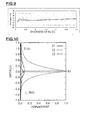
first conductor layer 16 formed of Au is changed. - Fig. 10 is a schematic graph of the displacement distribution of an elastic boundary wave when the thickness of Au = 0.05k and the thickness of Al = zero (U1 = longitudinal wave component, U2 = SH wave component, U3 = SV wave component; U1 to U3 are partial wave components constituting the elastic boundary wave). Fig. 11 is a graph illustrating the displacement distribution of an elastic boundary wave in an elastic boundary wave device when the thickness of Au = 0.05λ and the thickness of Al = 0.1λ (U1 = longitudinal wave component, U2 = SH wave component, U3 = SV wave component; U1 to U3 are partial wave components constituting the elastic boundary wave). In Fig. 10, the density of the
first medium 11 is 4640 kg/m3 and the density of thesecond medium 12 is 2210 kg/m3. In Fig. 10, the IDT does not have a layered structure including a plurality of conductors and is formed of a single conductor. The energy of an elastic boundary wave is proportional to ρU2, wherein U denotes the amplitude and ρ denotes the density of the IDT. Accordingly, the E1'/E2' is about 1.1. The E1/E2 determined from Fig. 11 is about 0.5. Hence, in the present embodiment, the relationship of E1/E2 < E1'/E2' is satisfied. - As shown in Fig. 11, since the high-density
first conductor layer 16 formed of Au is disposed on the side of thesecond medium 12, the center of vibrational energy distribution occurs on the side of thesecond medium 12. Thus, SiO2 can strongly compensate a positive TCD of the first medium 11 formed of a piezoelectric substance, because of its negative TCD. The TCD of the whole elastic boundary wave device can therefore be reduced effectively. - The present invention can be applied not only to the elastic
boundary wave device 10 functioning as an elastic boundary wave resonator, but also resonators or filters having various structures. Specifically, the present invention can also be applied widely to various filters or switches utilizing an elastic boundary wave, such as a ladder filter, a longitudinally coupled resonator filter, a transversely coupled resonator filter, a transversal filter, an elastic boundary wave optical switch, and an elastic boundary wave light filter. - The electrode material is not limited to Au or Al and may be another conducting material, such as Pt, Ag, Cu, Ni, Ti, Fe, W, or Ta or may be an alloy based on these conducting materials.
- Indeed, when the IDT has a layered structure including a first conductor layer and a second conductor layer, the density of the first conductor layer is formed of a high-density metal having a density of 7000 to 22000 kg/m3, as in Au, and the second conductor layer is formed of a low-density metal having a density of at least 1740 kg/m3 and less than 11000 kg/m3, as in Al. The metal constituting each conductor layer of the layered structure including the first conductor layer and the second conductor layer may be any metal, provided that the requirements for the densities of the metals constituting the first conductor layer and the second conductor layer and for the density ratio of the first conductor layer to the second conductor layer ρ1/ρ2 > 1.8 are satisfied.
- Examples of the metals constituting the first conductor layer and the second conductor layer include a combination of a metal constituting the first conductor layer selected from the group consisting of Pt, Au, Cu, Ag, Ni, Fe, W, Ta, Cr, and an alloy based thereon and a metal constituting the second conductor layer selected from the group consisting of Mg, Al, Ti, Cr, Ni, Cu, Ag, and an alloy based thereon.
- Furthermore, when the metal constituting the first conductor layer is Au, examples of the combination that satisfies the conditions described above include a combination with the metal constituting the second conductor layer selected from the group consisting of Al, Mg, Ti, Cr, Ni, Cu, Ag, and an alloy based thereon. Furthermore, when the metal constituting the first conductor layer is Cu, examples of the combination include a combination with the metal constituting the second conductor layer selected from the group consisting of Al, Mg, Ti, and an alloy based thereon. In the combination when the metal constituting the first conductor layer is Au or in the combination when the metal constituting the first conductor layer is Cu, the film thickness of the IDT is preferably 0.3 λ or less. This can reduce the absolute value of TCD to 10 ppm/°C or less.
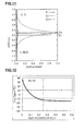
- Figs. 12 to 14 are graphs illustrating a change in TCD as a function of the film thickness of a second conductor layer in an IDT, when an elastic boundary wave device is produced as in the elastic boundary wave device with which the results illustrated in Figs. 4 to 6 are obtained, except that the first conductor layer and the second conductor layer have the structure described below.
- Specifically, Figs. 12 to 14 illustrate a change in TCD as a function of the normalized film thickness of Al, when the first conductor layer is formed of Au having a film thickness of 0.05λ and the second conductor layer is formed of Al.
- Figs. 13 and 14 illustrate a change in TCD as a function of the thickness of a Cu film or a Ag film, when the upper second conductor layer is formed of Cu or Ag. In Figs. 13 and 14, the film thickness of the first conductor layer formed of Au is also 0.05λ.
- In Figs. 12 to 14, the vertical alternate long and short dashed line indicates a point at which the Al film, the Cu film, and the Ag film of the second conductor layer have a thickness of 0.25λ. At this point, the total film thickness of the first conductor layer and the second conductor layer is 0.3λ.
- As shown in Figs. 12 to 14, when the film thickness of the IDT is 0.3λ or less, as the density of the metal constituting the second conductor layer increases from Al to Cu to Ag, a region, or the film thickness range of the second conductor layer, in which the absolute value of TCD is 10 ppm/°C or less decreases. This phenomenon results from the density ratio of the first conductor layer to the second conductor layer. The density ratio of Au/Ag is 1.83.
- In general, the region in which the absolute value of TCD is 10 ppm/°C or less can be the region in which the TCD is excellent. Thus, an elastic boundary wave device having the absolute value of TCD greater than 10 ppm/°C cannot necessarily be used. Depending on the requirements specification, an elastic boundary wave device having the characteristic out of the range described above can be used. In other words, the absolute value of TCD of 10 ppm/°C or less represents a preferred numerical range.
- Figs. 15 and 16 are graphs illustrating a change in TCD as a function of the film thickness of an Al film or a Ti film when the first conductor layer is formed of Cu having a film thickness of 0.1λ, and the second conductor layer is formed of Al or Ti.
- In Figs. 15 and 16, the vertical alternate long and short dashed line indicates a point at which the film thickness of the second conductor layer is 0.2λ. At this point, the total film thickness of the first conductor layer and the second conductor layer is 0.3λ.
- The reason that the thickness of the first conductor layer is 0.1λ when the first conductor layer is formed of Cu is that the density of Cu is 8.93 and is half the density of Au, which is 19.3. More specifically, in an elastic boundary wave, the distribution of energy concentration depends on the weight of an electrode. To equalize the energy concentration of the first conductor layer with that in Figs. 12 to 14, the normalized film thickness of Cu in Figs. 15 and 16 was set at 0.1λ.
- As shown in Figs. 15 and 16, when the film thickness of the IDT is 0.5λ or less or 0.3λ or less and the first conductor layer is formed of Cu, as the density of the metal constituting the second conductor layer increases, a region in which an excellent TCD can be achieved also decreases. This phenomenon results from the density ratio ρ1/ρ2 of the first conductor layer to the second conductor layer. The density ratio of Cu/Ti is 1.98, which satisfies ρ1/ρ2 > 1.8.
- In addition, a thin layer of Ti, Cr, NiCr, Ni, ZnO, or the like may be stacked on the first conductor layer or the second conductor layer to enhance the adhesiveness or the electric power resistance. In this case, the thin layer may be disposed between the first conductor layer or the second conductor layer and the first medium layer or the second medium layer, or between the first conductor layer and the second conductor layer. In particular, when the thin layer is disposed as an adherent layer at a portion where the IDT is in contact with the first medium and/or the second medium, the adhesiveness between the IDT and the first medium and/or the second medium can effectively be enhanced. Since the thin layer has only to have the adhesiveness or prevent the diffusion, the film thickness of the thin layer is in the range of 1 to 30 nm.
- Furthermore, in the present invention, in addition to the first conductor layer and the second conductor layer, at least one additional conductor layer, including a third conductor layer, may be stacked. In this case, the material used for the third conductor layer may be the same as or different from the material used for the first conductor layer or the second conductor layer. Thus, for example, the structure of electrodes may be Al/Au/Al. This structure can provide an elastic boundary wave device in which the electromechanical coupling coefficient K2 is moderately increased because of the presence of Au, the temperature coefficient of delay TCD is reduced to some extent, and electrode fingers have a small conductor resistance.
- Furthermore, while the
first medium 11 and the second medium 12 are stacked, at least one additional medium may be stacked. When another medium is stacked on the first medium 11 or thesecond medium 12, this third medium may be disposed between the first medium and the second medium. In this case, when the first conductor layer formed of a higher-density electrode material is disposed on the side of a medium formed of SiO2 or the like and having a negative TCD, the TCD of the whole device can be reduced. - Furthermore, in the present invention, before the formation of the second medium, the IDT may be adjusted by various methods, such as reverse sputtering, ion beam milling, reactive ion etching, and wet etching, to control the frequency. In addition, when a layered structure of second medium/third medium/IDT/first medium is used, the thickness of the third medium may be adjusted by the ion beam milling or etching, or an additional film may be formed by a deposition method, such as sputtering or vapor deposition, to control the frequency.
- The first medium and the second medium may be composed of various materials. Such materials include Si, glass, SiO2, SiC, ZnO, Ta2O5, PZT, AIN, Al2O3, LiTaO3, LiNbO3, and KN (potassium niobate). In particular, when a piezoelectric substance is used as the
first medium 11, in addition to LiNb2O3, various piezoelectric materials, such as ZnO, Ta2O5, PZT, and LiTaO3, may be used. - Furthermore, when a dielectric material is used as the
second medium 12, examples of such a dielectric material include, in addition to SiO2 glass, SiC, AIN, and Al2O3. As described above, because a piezoelectric substance generally has a positive TCD, a dielectric material having a negative TCD is preferably used as a material of the second medium 12 to reduce the TCD. Examples of the dielectric material having a negative TCD include, in addition to SiO2 quartz crystal, lithium tetraborate (LBO), langasite, langanite, and glass. - In the present invention, a laminated body including a first medium and a second medium or a laminated body further including a third medium may have an outer protective layer to increase the strength or prevent the intrusion of a corrosive gas. The protective layer may be formed of various materials, including, but not limited to, polyimide, an epoxy resin, an inorganic insulating material, such as titanium oxide, aluminum nitride, or aluminum oxide, and a metal, such as Au, Al, or W. Furthermore, in the presence of the protective layer or in the absence of the protective layer, an elastic boundary wave device may be encapsulated.
Claims (13)
- An elastic boundary wave device comprising: a first medium having a positive temperature coefficient of delay in a propagation direction of an elastic boundary wave; a second medium having a negative temperature coefficient of delay in a propagation direction of an elastic boundary wave; and an IDT including laminated conductor layers disposed between the first medium and the second medium,
wherein the lamination direction of the first medium and the second medium is the thickness direction of the IDT, a plane that halves the IDT in the thickness direction is taken as an interface, the energy of an elastic boundary wave present on the first medium side of the interface is denoted as E1, and the energy of an elastic boundary wave present on the second medium side of the interface is denoted as E2, and
if the IDT were composed only of a conductor layer of a single metal having the highest density among the laminated conductor layers of the IDT, when the energy of an elastic boundary wave present on the first medium side of the interface is denoted as E1' and the energy of an elastic boundary wave present on the second medium side of the interface is denoted as E2', the energies of an elastic boundary wave would satisfy the relationship of E1/E2 < E1'/E2' so that the sonic velocity of an elastic boundary wave in the IDT composed of the laminated conductor layers is equal to the sonic velocity of an elastic boundary wave if the IDT were formed only of the conductor layer having the highest density. - The elastic boundary wave device according to Claim 1, wherein the IDT has a layered structure composed of a first conductor layer formed of a metal having a density in the range of 7000 to 22000 kg/m3 and a second conductor layer formed of a metal having a density of at least 1740 kg/m3 and less than 11000 kg/m3,
the density ρ1 of the first conductor layer and the density ρ2 of the second conductor layer satisfy the relationship of ρ1/ρ2 > 1.8, and
a conductor layer disposed on the second medium side of the IDT is the first conductor layer. - The elastic boundary wave device according to Claim 2, wherein the thickness H of the first conductor layer and the electrode finger period λ of the IDT satisfy the relationship of 0.034λ < H < 0.5λ.
- The elastic boundary wave device according to Claim 2 or 3, further comprising an adherent layer disposed at a portion at which the IDT is in contact with the first medium and/or the second medium.
- An elastic boundary wave device comprising: a first medium having a positive temperature coefficient of delay in a propagation direction of an elastic boundary wave; a second medium having a negative temperature coefficient of delay in a propagation direction of an elastic boundary wave; and an IDT disposed between the first medium and the second medium, wherein
the IDT has a layered structure composed of a first conductor layer formed of a metal having a density in the range of 7000 to 22000 kg/m3 and a second conductor layer formed of a metal having a density of at least 1740 kg/m3 and less than 11000 kg/m3,
the density ρ1 of the first conductor layer and the density ρ2 of the second conductor layer satisfy the relationship of ρ1/ρ2 > 1.8,
a conductor layer disposed on the second medium side of the IDT is the first conductor layer, and
the thickness H of the first conductor layer and the electrode finger period λ of the IDT satisfy the relationship of 0.034λ < H < 0.5λ. - The elastic boundary wave device according to Claim 5, further comprising an adherent layer disposed at a portion at which the IDT is in contact with the first medium and/or the second medium.
- The elastic boundary wave device according to any one of Claims 1 to 6,
wherein the first medium is composed of one material selected from the group consisting of LiTaO3 LiNbO3, quartz crystal, PZT, LBO, langasite, langanite, and glass. - The elastic boundary wave device according to any one of Claims 1 to 7,
wherein the second medium is composed of at least one material selected from the group consisting of SiO2, quartz crystal, LBO, langasite, langanite, and glass, the material being different from the material used for the first medium. - The elastic boundary wave device according to any one of Claims 2 to 6,
wherein the metal constituting the first conductor layer is a metal selected from the group consisting of Pt, Au, Cu, Ag, Ni, Fe, W, Ta, Cr, and an alloy based thereon, and
the metal constituting the second conductor layer is a metal selected from the group consisting of Mg, Al, Ti, Cr, Ni, Cu, Ag, and an alloy based thereon. - The elastic boundary wave device according to any one of Claims 2 to 9,
wherein the metal constituting the first conductor layer is Au, and the metal constituting the second conductor layer is a metal selected from the group consisting of Al, Mg, Ti, Cr, Ni, Cu, Ag, and an alloy based thereon. - The elastic boundary wave device according to any one of Claims 2 to 9,
wherein the metal constituting the first conductor layer is Cu, and the metal constituting the second conductor layer is a metal selected from the group consisting of Al, Mg, Ti, and an alloy based thereon. - The elastic boundary wave device according to Claim 10 or 11, wherein the film thickness of the IDT is 0.3λ or less.
- The elastic boundary wave device according to any one of Claims 1 to 9, further comprising a reflector disposed between the first medium and the second medium, the reflector being formed of the same electrode material as the IDT.
Applications Claiming Priority (2)
| Application Number | Priority Date | Filing Date | Title |
|---|---|---|---|
| JP2005148064 | 2005-05-20 | ||
| PCT/JP2006/309572 WO2006123585A1 (en) | 2005-05-20 | 2006-05-12 | Elastic boundary wave device |
Publications (2)
| Publication Number | Publication Date |
|---|---|
| EP1883158A1 true EP1883158A1 (en) | 2008-01-30 |
| EP1883158A4 EP1883158A4 (en) | 2009-02-18 |
Family
ID=37431161
Family Applications (1)
| Application Number | Title | Priority Date | Filing Date |
|---|---|---|---|
| EP06732553A Withdrawn EP1883158A4 (en) | 2005-05-20 | 2006-05-12 | Elastic boundary wave device |
Country Status (6)
| Country | Link |
|---|---|
| US (1) | US7411473B2 (en) |
| EP (1) | EP1883158A4 (en) |
| JP (1) | JP4466655B2 (en) |
| KR (1) | KR100839788B1 (en) |
| CN (1) | CN1989692B (en) |
| WO (1) | WO2006123585A1 (en) |
Families Citing this family (14)
| Publication number | Priority date | Publication date | Assignee | Title |
|---|---|---|---|---|
| US7471171B2 (en) * | 2006-02-28 | 2008-12-30 | Fujitsu Media Devices Limited | Elastic boundary wave device, resonator, and filter |
| CN101523720B (en) * | 2006-10-12 | 2012-07-04 | 株式会社村田制作所 | Elastic boundary-wave device |
| WO2008062639A1 (en) * | 2006-11-24 | 2008-05-29 | Murata Manufacturing Co., Ltd. | Elastic boundary wave device manufacturing method, and elastic boundary wave device |
| JP4811516B2 (en) * | 2007-03-06 | 2011-11-09 | 株式会社村田製作所 | Boundary acoustic wave device |
| CN101796727B (en) * | 2007-08-14 | 2016-04-27 | 太阳诱电株式会社 | Boundary acoustic wave device |
| DE102008033704B4 (en) * | 2008-07-18 | 2014-04-03 | Epcos Ag | Electronic component |
| JP5338912B2 (en) * | 2009-09-30 | 2013-11-13 | 株式会社村田製作所 | Elastic wave filter device and duplexer including the same |
| JP5664655B2 (en) * | 2010-09-17 | 2015-02-04 | 株式会社村田製作所 | Elastic wave device |
| JP5697751B2 (en) * | 2011-03-25 | 2015-04-08 | スカイワークス・パナソニック フィルターソリューションズ ジャパン株式会社 | Elastic wave device with high-order transverse mode wave suppressed |
| CN205992889U (en) * | 2014-03-31 | 2017-03-01 | 株式会社村田制作所 | SAW filter |
| JP2017157944A (en) * | 2016-02-29 | 2017-09-07 | 株式会社村田製作所 | Surface acoustic wave device and duplexer having transmission/reception filter using the same |
| JP6922931B2 (en) * | 2016-12-05 | 2021-08-18 | 株式会社村田製作所 | Surface acoustic wave device, high frequency front end circuit and communication device |
| CN108055017A (en) * | 2018-02-11 | 2018-05-18 | 海宁市瑞宏科技有限公司 | A kind of resonator structure for ultra-wide band SAW filter design |
| JP2020092321A (en) * | 2018-12-05 | 2020-06-11 | 太陽誘電株式会社 | Acoustic wave device and manufacturing method thereof, filter, and multiplexer |
Citations (4)
| Publication number | Priority date | Publication date | Assignee | Title |
|---|---|---|---|---|
| EP0920129A1 (en) * | 1997-05-08 | 1999-06-02 | Kabushiki Kaisha Toshiba | Elastic boundary wave device and method of its manufacture |
| EP1401099A1 (en) * | 2002-04-15 | 2004-03-24 | Matsushita Electric Industrial Co., Ltd. | Surface acoustic wave device, and mobile communication device and sensor both using same |
| WO2004095699A1 (en) * | 2003-04-18 | 2004-11-04 | Murata Manufacturing Co., Ltd. | Elastic boundary wave device |
| US20050099091A1 (en) * | 2003-11-12 | 2005-05-12 | Fujitsu Media Devices Limited | Elastic boundary wave device and method of manufacturing the same |
Family Cites Families (7)
| Publication number | Priority date | Publication date | Assignee | Title |
|---|---|---|---|---|
| JPS5830217A (en) | 1981-08-17 | 1983-02-22 | Hitachi Ltd | Acoustic wave device |
| DE4132309A1 (en) | 1991-09-27 | 1993-04-01 | Siemens Ag | Stoneley wave component - having finger electrodes made of material and of height to produce no wave reflections |
| JP2800905B2 (en) * | 1991-10-28 | 1998-09-21 | 富士通株式会社 | Surface acoustic wave filter |
| JP3524188B2 (en) * | 1995-01-23 | 2004-05-10 | 沖電気工業株式会社 | Surface acoustic wave device |
| KR100851219B1 (en) * | 2003-02-10 | 2008-08-07 | 가부시키가이샤 무라타 세이사쿠쇼 | Elastic boundary wave device |
| WO2005036744A1 (en) * | 2003-10-10 | 2005-04-21 | Murata Manufacturing Co., Ltd. | Boundary acoustic wave device |
| JP2008235950A (en) * | 2005-05-26 | 2008-10-02 | Murata Mfg Co Ltd | Elastic boundary wave device |
-
2006
- 2006-05-12 KR KR1020077000406A patent/KR100839788B1/en active IP Right Grant
- 2006-05-12 CN CN2006800004487A patent/CN1989692B/en active Active
- 2006-05-12 JP JP2006545827A patent/JP4466655B2/en active Active
- 2006-05-12 EP EP06732553A patent/EP1883158A4/en not_active Withdrawn
- 2006-05-12 WO PCT/JP2006/309572 patent/WO2006123585A1/en active Application Filing
-
2007
- 2007-01-19 US US11/624,720 patent/US7411473B2/en active Active
Patent Citations (4)
| Publication number | Priority date | Publication date | Assignee | Title |
|---|---|---|---|---|
| EP0920129A1 (en) * | 1997-05-08 | 1999-06-02 | Kabushiki Kaisha Toshiba | Elastic boundary wave device and method of its manufacture |
| EP1401099A1 (en) * | 2002-04-15 | 2004-03-24 | Matsushita Electric Industrial Co., Ltd. | Surface acoustic wave device, and mobile communication device and sensor both using same |
| WO2004095699A1 (en) * | 2003-04-18 | 2004-11-04 | Murata Manufacturing Co., Ltd. | Elastic boundary wave device |
| US20050099091A1 (en) * | 2003-11-12 | 2005-05-12 | Fujitsu Media Devices Limited | Elastic boundary wave device and method of manufacturing the same |
Non-Patent Citations (2)
| Title |
|---|
| See also references of WO2006123585A1 * |
| T. IRINO; T. WATANABE; Y. SHIMIZU: "Zero slope temperature SiO2/LiTaO3 structure substrate for Stoneley waves" IEEE 1987 ULTRASONICS SYMPOSIUM PROCEEDINGS, vol. 1, 14 October 1987 (1987-10-14), - 16 October 1987 (1987-10-16) pages 257-260, XP002508489 Denver, CO, USA * |
Also Published As
| Publication number | Publication date |
|---|---|
| US7411473B2 (en) | 2008-08-12 |
| KR20070015477A (en) | 2007-02-02 |
| JP4466655B2 (en) | 2010-05-26 |
| EP1883158A4 (en) | 2009-02-18 |
| WO2006123585A1 (en) | 2006-11-23 |
| JPWO2006123585A1 (en) | 2008-12-25 |
| CN1989692B (en) | 2012-04-25 |
| CN1989692A (en) | 2007-06-27 |
| KR100839788B1 (en) | 2008-06-19 |
| US20070176711A1 (en) | 2007-08-02 |
Similar Documents
| Publication | Publication Date | Title |
|---|---|---|
| US7411473B2 (en) | Elastic boundary wave device | |
| US7456544B2 (en) | Boundary acoustic wave device | |
| US8710713B2 (en) | Boundary acoustic wave device | |
| US9413334B2 (en) | Elastic wave device using SH surface acoustic wave | |
| JP4356613B2 (en) | Boundary acoustic wave device | |
| JP4483785B2 (en) | Boundary acoustic wave device | |
| JP4715922B2 (en) | Boundary acoustic wave device | |
| EP2763315A1 (en) | Elastic wave device | |
| WO2012086639A1 (en) | Elastic wave device and production method thereof | |
| EP1722473A1 (en) | Boundary acoustic wave device | |
| JP4182157B2 (en) | Surface wave device | |
| US20110254406A1 (en) | Boundary acoustic wave device | |
| JP4001157B2 (en) | Boundary acoustic wave device | |
| KR102629355B1 (en) | elastic wave device | |
| US20220407493A1 (en) | Acoustic wave device | |
| JP2012169760A (en) | Surface acoustic wave device | |
| WO2023003005A1 (en) | Elastic wave device | |
| WO2023003006A1 (en) | Elastic wave device |
Legal Events
| Date | Code | Title | Description |
|---|---|---|---|
| PUAI | Public reference made under article 153(3) epc to a published international application that has entered the european phase |
Free format text: ORIGINAL CODE: 0009012 |
|
| 17P | Request for examination filed |
Effective date: 20070115 |
|
| AK | Designated contracting states |
Kind code of ref document: A1 Designated state(s): AT BE BG CH CY CZ DE DK EE ES FI FR GB GR HU IE IS IT LI LT LU LV MC NL PL PT RO SE SI SK TR |
|
| DAX | Request for extension of the european patent (deleted) | ||
| RIC1 | Information provided on ipc code assigned before grant |
Ipc: H03H 9/02 20060101AFI20090108BHEP Ipc: H03H 9/145 20060101ALI20090108BHEP |
|
| A4 | Supplementary search report drawn up and despatched |
Effective date: 20090119 |
|
| 17Q | First examination report despatched |
Effective date: 20090423 |
|
| GRAP | Despatch of communication of intention to grant a patent |
Free format text: ORIGINAL CODE: EPIDOSNIGR1 |
|
| INTG | Intention to grant announced |
Effective date: 20131011 |
|
| STAA | Information on the status of an ep patent application or granted ep patent |
Free format text: STATUS: THE APPLICATION IS DEEMED TO BE WITHDRAWN |
|
| 18D | Application deemed to be withdrawn |
Effective date: 20140222 |