EP1883151A2 - Permanent magnet excited transverse flux linear motor with normal force compensation structure - Google Patents
Permanent magnet excited transverse flux linear motor with normal force compensation structure Download PDFInfo
- Publication number
- EP1883151A2 EP1883151A2 EP07113189A EP07113189A EP1883151A2 EP 1883151 A2 EP1883151 A2 EP 1883151A2 EP 07113189 A EP07113189 A EP 07113189A EP 07113189 A EP07113189 A EP 07113189A EP 1883151 A2 EP1883151 A2 EP 1883151A2
- Authority
- EP
- European Patent Office
- Prior art keywords
- mover
- stator
- permanent magnets
- iron core
- iron cores
- Prior art date
- Legal status (The legal status is an assumption and is not a legal conclusion. Google has not performed a legal analysis and makes no representation as to the accuracy of the status listed.)
- Granted
Links
- 230000004907 flux Effects 0.000 title claims abstract description 58
- XEEYBQQBJWHFJM-UHFFFAOYSA-N Iron Chemical group [Fe] XEEYBQQBJWHFJM-UHFFFAOYSA-N 0.000 claims abstract description 153
- 238000004804 winding Methods 0.000 claims abstract description 28
- 239000012256 powdered iron Substances 0.000 claims description 19
- 229910052742 iron Inorganic materials 0.000 claims description 16
- 238000000465 moulding Methods 0.000 claims description 11
- 239000007787 solid Substances 0.000 description 17
- 238000004519 manufacturing process Methods 0.000 description 9
- RYGMFSIKBFXOCR-UHFFFAOYSA-N Copper Chemical compound [Cu] RYGMFSIKBFXOCR-UHFFFAOYSA-N 0.000 description 2
- 230000005540 biological transmission Effects 0.000 description 2
- 229910052802 copper Inorganic materials 0.000 description 2
- 239000010949 copper Substances 0.000 description 2
- 230000006866 deterioration Effects 0.000 description 2
- 238000000034 method Methods 0.000 description 1
- 238000012986 modification Methods 0.000 description 1
- 230000004048 modification Effects 0.000 description 1
- 239000002245 particle Substances 0.000 description 1
- 238000012545 processing Methods 0.000 description 1
- 230000010349 pulsation Effects 0.000 description 1
- 238000005245 sintering Methods 0.000 description 1
- 238000012546 transfer Methods 0.000 description 1
Images


Classifications
-
- H—ELECTRICITY
- H02—GENERATION; CONVERSION OR DISTRIBUTION OF ELECTRIC POWER
- H02K—DYNAMO-ELECTRIC MACHINES
- H02K41/00—Propulsion systems in which a rigid body is moved along a path due to dynamo-electric interaction between the body and a magnetic field travelling along the path
- H02K41/02—Linear motors; Sectional motors
- H02K41/03—Synchronous motors; Motors moving step by step; Reluctance motors
- H02K41/031—Synchronous motors; Motors moving step by step; Reluctance motors of the permanent magnet type
- H02K41/033—Synchronous motors; Motors moving step by step; Reluctance motors of the permanent magnet type with armature and magnets on one member, the other member being a flux distributor
-
- H—ELECTRICITY
- H02—GENERATION; CONVERSION OR DISTRIBUTION OF ELECTRIC POWER
- H02K—DYNAMO-ELECTRIC MACHINES
- H02K2213/00—Specific aspects, not otherwise provided for and not covered by codes H02K2201/00 - H02K2211/00
- H02K2213/03—Machines characterised by numerical values, ranges, mathematical expressions or similar information
Definitions
- the present invention relates to a permanent magnet excited transverse flux linear motor and, more particularly, to a permanent magnet excited transverse flux linear motor with a normal force compensation structure in which a stator is inserted in the middle of leg portions of a mover so as to compensate normal forces generated between the mover and the stator, thus reducing noise and vibration.
- a motor is a device that converts electrical energy into mechanical energy and fundamentally requires a high output power (output power/motor weight: kW/kg) and a high efficiency (output power/input power).
- the linear motors may be classified into a longitudinal flux motor and a transverse flux motor according to the direction of a magnetic flux.
- the direction of the magnetic flux is the same as the moving direction of the motor in the longitudinal flux motor, whereas, the direction of the magnetic flux is transverse to the moving direction of the motor in the transverse flux motor.
- the direction of an applied current is perpendicular to the moving direction of the motor, whereas, in case of the transverse flux motor, the direction of an applied current is the same as the moving direction of the motor.
- the transverse flux motor In the transverse flux motor, a space (electrical circuit) in which a winding can be performed is separated from a space (magnetic circuit) in which a magnetic flux can flow. Accordingly, the transverse flux motor can increase the output power density and provide a variety of designs, compared with the longitudinal flux motor in which the electrical circuit and the magnetic circuit are coupled with each other.
- the transverse flux motor has advantages in that the copper loss is small and the amount of copper used therein is small, since the winding is provided in the form of a ring, compared with the longitudinal flux motor having a lot of end-windings.
- the permanent magnet excited transverse flux linear motor has a structure in which the mover faces the stator and the left and right normal forces are applied to the mover and stator structure, large normal forces are generated to cause noise and vibration.
- an object of the present invention is to provide a permanent magnet excited transverse flux linear motor with a normal force compensation structure in which a stator is inserted in the middle of leg portions of a mover so as to compensate normal forces generated between the mover and the stator, thus reducing noise and vibration.
- another object of the present invention is to provide a permanent magnet excited transverse flux linear motor that can reduce iron loss using a laminated iron core or a powdered iron core as a stator iron core.
- the present invention provides a permanent magnet excited transverse flux linear motor with a normal force compensation structure comprising: a mover including iron cores and permanent magnets, arranged alternately with each other, and a winding coil winding the mover iron cores and the mover permanent magnets; and a stator having an air gap between the mover and itself and arranged longitudinally in the moving direction of the mover, wherein the mover iron cores and the mover permanent magnets are formed in the shape of " ⁇ ", of which both leg portions and middle portions are arranged in a straight line, the winding coil winds the both leg portions of the mover iron cores and the mover permanent magnets in the shape of " ⁇ ", respectively, and an iron core of the stator having a concave-convex shape, in which a plurality of projections formed along the length of a central portion and projected from the central portion to the left and right sides alternately, is arranged to be inserted in the middle of the both leg portions of the mover iron cores and the mover permanent magnets
- the projections, which projected to the left and right sides alternately, are repeatedly formed at intervals of " ⁇ P ", which is a pole pitch of the mover, and thereby adjacent projections in the same side are arranged to be repeated at intervals of "2 ⁇ P ".
- the iron core of the stator has a laminated structure in which iron plates are laminated in a plurality of layers.
- the iron core of the stator is a powdered iron core formed by molding iron powder.
- each of the mover iron cores features a powdered iron core formed by molding iron powder.
- the present invention provides a permanent magnet excited transverse flux linear motor with a normal force compensation structure comprising: a mover including iron cores and permanent magnets, arranged alternately with each other, and a winding coil winding the mover iron cores and mover the permanent magnets; and a stator having an air gap between the mover and itself and arranged longitudinally in the moving direction of the mover, wherein the mover iron cores and the mover permanent magnets are formed in the shape of " ⁇ ", of which both leg portions and middle portions are arranged in a straight line, the winding coil winds the both leg portions of the mover iron cores and the mover permanent magnets in the shape of " ⁇ ", respectively, and an iron core of the stator having a skewed structure, in which a plurality of projections are arranged at predetermined intervals on the top of a base along the longitudinal direction thereof to be skewed on the top surface of the base, is arranged to be inserted in the middle of the both leg portions of the mover iron cores
- a pitch between left and right ends of each of the projections is arranged to be skewed by " ⁇ P ", which is a pole pitch of the mover, and such projections are arranged to be repeated at intervals of "2 ⁇ P " along the length of a base thereof.
- the iron core of the stator features a powdered iron core formed by molding iron powder.
- the present invention provides a permanent magnet excited transverse flux linear motor with a normal force compensation structure comprising: a mover including iron cores and permanent magnets, arranged alternately with each other, and a winding coil winding the mover iron cores and the mover permanent magnets; and a stator having an air gap between the mover and itself and arranged longitudinally in the moving direction of the mover, wherein the mover iron cores and the mover permanent magnets are formed in the shape of " ⁇ " having leg portions and skewed by a pole pitch of " ⁇ P ", the winding coil winds the both leg portions of the mover iron cores and the mover permanent magnets in the shape of " ⁇ ", respectively, and an iron core of the stator including a plurality of projections arranged at predetermined intervals on the top of a base along the longitudinal direction thereof is arranged to be inserted in the middle of the both leg portions of the mover iron cores and the mover permanent magnets.
- the respective projections are arranged perpendicularly to the moving direction of the mover, and the plurality of such projections are arranged to be repeated at intervals of "2 ⁇ P ".
- the iron core of the stator is a powdered iron core formed by molding iron powder.
- each of the mover iron cores is a powdered iron core formed by molding iron powder.
- the present invention provides a permanent magnet excited transverse flux linear motor with a normal force compensation structure in which the shapes of a mover and a stator are improved and, at the same time, the position of the stator is changed so as to compensate normal forces generated between the mover and the stator, thus reducing noise and vibration.
- Conventional permanent magnet excited transverse flux linear motors have a structure in which mover iron cores and mover permanent magnets are skewed from each other by a pole pitch of " ⁇ P ". Moreover, since the magnetic flux of the conventional permanent magnet excited transverse flux linear motor flows three dimensionally as well known in the art, an ordinary laminated iron core cannot be used, thus a solid iron core is used. However, in a case where the solid iron core is employed, the motor performance deteriorates and the deterioration becomes severe due to iron loss in a high speed range.
- the stator is positioned in the middle of the mover to compensate normal forces generated between the stator and the mover, thus reducing noise and vibration, as shown in FIG. 1.
- the present invention provides a permanent magnet excited transverse flux linear motor that can reduce iron loss using a laminated iron core having a concave-convex shape or a powdered iron core as a stator iron core and facilitate the manufacturing process of movers by arranging mover iron cores and mover permanent magnets in a straight line.
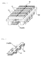
- FIG. 1 is a perspective view showing a mover and a stator of a permanent magnet excited transverse flux linear motor with a normal force compensation structure in accordance with a preferred embodiment of the present invention.
- a mover 10 comprises mover iron cores 11 and mover permanent magnets 12 in the shape of " ⁇ ", of which both leg portions and middle portions are arranged in a straight line, and a winding coil 30 including coils winding the both leg portions of the mover iron cores 11 and the mover permanent magnets 12 in the shape of " ⁇ " respectively, as shown in FIG. 1, differently from the conventional iron cores and permanent magnets.
- the mover permanent magnets 12 are inserted between the mover iron cores 11, in which the magnetic poles of adjacent mover permanent magnets 12 along the mover iron core 11 are arranged in the opposite direction, i.e., in the order of ⁇ and ⁇ alternately as shown in FIG. 1. Accordingly, the magnetic poles of N and S are generated alternately in the motor iron cores 11.
- a laminated stator iron core 20 having a concave-convex shape is used as the stator arranged longitudinally in the moving direction of the mover 10.
- FIG. 2 is a perspective view showing the laminated stator iron core 20 in accordance with the preferred embodiment of the present invention, wherein a stator iron core 21a has a laminated structure in which iron plates are laminated in a plurality of layers to reduce the iron loss.
- the laminated stator iron core 21a has the concave-convex shape, in which a plurality of projections 23 is formed to be projected along the length of a central portion 22.
- the projections 23 are projected from the central portion 22 to the left and right sides alternately.
- the laminated stator iron core 21a having the above-described concave-convex shape is arranged in the middle of the inside of the mover iron cores 11 and the mover permanent magnets 12 in the shape of " ⁇ " and, more precisely, is arranged in the middle of both leg portions of the mover iron cores 11 and the permanent magnets 12 as shown in FIG. 1.
- the left and right teeth of the laminated stator iron core 21a i.e., the left and right projections 23 are arranged to be skewed from each other by a pole pitch of " ⁇ P " of the mover 10 in FIG. 1 so that a thrust force generated in an air gap between the mover and the stator is forwarded to the direction to move.
- the projections 23 projected to the left and right sides are repeatedly formed at intervals of " ⁇ P ", which is a pole pitch of the mover 10 in FIG. 1, that is, the left and right projections 23 are repeatedly formed in a cycle of " ⁇ P ". Accordingly, the adjacent projections 23 in the same side are arranged to be repeated at intervals of "2 ⁇ P ".
- stator iron core 21a having the concave-convex shape is arranged in the middle of the leg portions of the mover iron cores 11 and the permanent magnets 12, normal forces generated between the mover 10 and the stator 20 can be compensated with each other, thus reducing noise and vibration.
- the linear motor of the present invention applies the stator iron core 21a having the concave-convex shape in which the projections 23 are arranged by a pole pitch of " ⁇ P " to the left and right sides alternately, the thrust force in the air gap can be generated in the direction to move, even though the mover iron cores 11 and the mover permanent magnets 12 are arranged in a straight line. Accordingly, it is possible to manufacture the mover iron cores and the permanent magnets more readily with the straight line structure.
- the laminated stator iron core 21a is used, it is possible to reduce the iron loss compared with the used of the solid iron core.
- FIG. 3 is a perspective view showing another example of a stator iron core which can be used in the linear motor in accordance with the present invention, in which the stator iron core 21b having the same shape as the laminated stator iron core but formed in a solid type is shown.
- the solid stator iron core 21b is arranged to replace the laminated stator iron core 21a shown in FIG. 1, that is, if the solid stator iron core 21b is arranged in the middle of the leg portions of the mover iron cores 11 and the mover permanent magnets 12, the normal forces can be compensated with each other to reduce noise and vibration.
- Such a solid stator iron core 21b is applicable to a case where the stator is required to have a solid structure at low speed.
- a powdered iron core manufactured using iron powder in the same shapes as the laminated stator iron core 21a and the solid stator iron core 21b respectively shown in FIGs. 2 and 3, can be applied. Accordingly, it is possible to apply the powdered iron core in the same concave-convex shape to reduce the iron loss at high speed.
- the powdered iron core is manufactured by press-molding iron powder in a mold and sintering the molded iron power.
- press-molding iron powder in a mold When using such manufacturing process, it is possible to manufacture the iron cores with complex and varied shapes.
- FIG. 4 is a perspective view showing another example of a stator iron core which can be used in the linear motor in accordance with the present invention, in which the stator iron core 21c formed integrally with a plurality of projections 25 arranged at predetermined intervals on the top of a base 24 along the longitudinal direction thereof is shown.
- the projections 25 are arranged to be projected upward on the top surface of the base 24 and, at the same time, to be skewed on the top surface of the base 24 so that the pitch between left and right ends becomes a pole pitch of " ⁇ P " of the mover.
- the projections 25 corresponding to the teeth of the stator iron core 21c are arranged repeatedly at intervals of "2 ⁇ p " in the longitudinal direction of the stator iron core 21c (or the base 24), i.e., in the moving direction of the mover.
- the solid stator iron core 21c having the skewed shape as described above is arranged to be inserted in the middle of the inside of the mover iron cores 11 and the mover permanent magnets 12 in the shape of " ⁇ ", i.e., in the middle of the both leg portions of the mover iron cores 11 and the mover permanent magnets 12 in the same manner as the stator iron cores 21a and 21b, respectively shown in FIGs. 2 and 3.
- the manufacturing process of the solid stator iron core 21c having the skewed shape is more simplified than the solid stator iron core 21b having the concave-convex shape shown in FIG. 3. Moreover, it is possible to apply a powdered iron core 21c having the shape of FIG. 4 in order to reduce the iron loss at high speed.
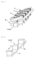
- FIG. 5 is a perspective view showing a mover and a stator of a permanent magnet excited transverse flux linear motor in accordance with another embodiment of the present invention.
- the mover iron cores 11 and the mover permanent magnets 12 are formed in the shape of " ⁇ " having leg portions and skewed by a pole pitch of " ⁇ P ".
- the mover 10 has a skewed structure, differently from the embodiment of FIG. 1, and the stator iron core 21a is arranged to be inserted in the middle of both leg portions of the mover iron cores 11 and the mover permanent magnets 12 and with left and right air gaps.
- the mover iron cores 11 and the mover permanent magnets 12 have the skewed structure in which the pitch between left and right ends becomes a pole pitch of " ⁇ P " of the mover.
- the mover permanent magnets 12 are inserted between the mover iron cores 11, in which the magnetic poles of adjacent mover permanent magnets 12 along the mover iron core 11 are arranged in the opposite direction, i.e., in the order of ⁇ and ⁇ alternately as shown in FIG. 5. Accordingly, the magnetic poles of N and S are generated alternately in the mover iron cores 11.
- the winding core 30 comprises separate coils winding the both leg portions of the mover iron cores 11 and the mover permanent magnets 12 in the shape of " ⁇ ".
- FIGs. 6 and 7 are perspective views showing stator iron cores which can be applied to the embodiment of FIG. 5, in which examples of stator iron cores 21d and 21e formed integrally with a plurality of projections 25 arranged at predetermined intervals on the top of a base 24 along the longitudinal direction thereof are shown.
- the projections 25 are arranged to be projected upward on the top surface of the base 24, and the respective projections 25 are arranged perpendicularly to the moving direction of the mover (perpendicularly to the longitudinal direction of the base 24) on the top surface of the base 24.
- the projections 23 as described above are arranged repeatedly at intervals of "2 ⁇ P " in the longitudinal direction of the stator iron cores 21d and 21e, i.e., in the moving direction of the mover.
- the mover 10 in FIG. 1 is formed to be skewed by a pole pitch of " ⁇ P " and the teeth (projections) of the stator iron cores 21d and 21e arranged in the middle of the leg portions of the mover are provided in a straight line, the mover can be moved back and forth along the longitudinal direction of the stator iron cores 21d and 21e by the thrust force generated in an air gap between the mover and the stator.
- the linear motor in FIG. 5 has the structure of the mover and the stator similar to the structure of the linear motor in FIG. 1, which the stator 20 is arranged in the middle of the leg portions of the mover 10, so that the normal forces generated between the mover and the stator may be compensated with each other, thus reducing noise and vibration.
- FIG. 6 shows the stator iron core 21d formed in such a manner that the projections 25 corresponding to the teeth are formed separately and then attached integrally to the base 24 in the permanent magnet excited transverse flux liner motor having the mover formed in the skewed shape.
- the processing cost can be saved if the projections 25 are formed separately and then attached integrally to the base 24 to manufacture one stator iron core 21d.
- a powdered iron core having the same shape as FIG. 6 can be applied to reduce the iron loss at high speed.
- FIG. 7 shows the stator iron core 21e formed integrally in the permanent magnet excited transverse flux liner motor having the mover formed in the skewed shape.
- the stator iron core 21e formed integrally, i.e., the solid stator iron core, is suitable for a case where the stator is required to have a strong solid structure.
- a powdered iron core having the same shape as FIG. 7 can be applied to reduce the iron loss at high speed.
- the stator is arranged to be inserted in the middle of the leg portions of the mover to compensate the normal forces generated between the mover and the stator, thus reducing noise and vibration.
- the laminated iron core or the powdered iron core is used as the stator iron core to reduce the iron loss.
Abstract
Description
- The present invention relates to a permanent magnet excited transverse flux linear motor and, more particularly, to a permanent magnet excited transverse flux linear motor with a normal force compensation structure in which a stator is inserted in the middle of leg portions of a mover so as to compensate normal forces generated between the mover and the stator, thus reducing noise and vibration.
- In general, a motor is a device that converts electrical energy into mechanical energy and fundamentally requires a high output power (output power/motor weight: kW/kg) and a high efficiency (output power/input power).
- Especially, in a case where linear motion is obtained using a power transmission system such as a rotary motor, a ball screw, etc., the system becomes complicated and produces particles and dusts, thus it cannot form a clean transfer system. Accordingly, the use of linear motors has been increased recently in linear transmission systems.
- The linear motors may be classified into a longitudinal flux motor and a transverse flux motor according to the direction of a magnetic flux.
- Here, the direction of the magnetic flux is the same as the moving direction of the motor in the longitudinal flux motor, whereas, the direction of the magnetic flux is transverse to the moving direction of the motor in the transverse flux motor.
- That is, in case of the longitudinal flux motor, the direction of an applied current is perpendicular to the moving direction of the motor, whereas, in case of the transverse flux motor, the direction of an applied current is the same as the moving direction of the motor.
- In the transverse flux motor, a space (electrical circuit) in which a winding can be performed is separated from a space (magnetic circuit) in which a magnetic flux can flow. Accordingly, the transverse flux motor can increase the output power density and provide a variety of designs, compared with the longitudinal flux motor in which the electrical circuit and the magnetic circuit are coupled with each other.
- Moreover, the transverse flux motor has advantages in that the copper loss is small and the amount of copper used therein is small, since the winding is provided in the form of a ring, compared with the longitudinal flux motor having a lot of end-windings.
- Meanwhile, as well known in the art, since a linear motor is large in volume and uses many permanent magnets, the size of the system is large and its price is high.
- To solve such problems, it is possible to use permanent magnet excited transverse flux linear motors that generate a high thrust force per unit weight and require a smaller number of expensive permanent magnets.
- However, it has been known that the existing permanent magnet excited transverse flux linear motors have numerous limitations in their use due to noise and vibration caused by the normal forces and the pulsation of the thrust force.
- Especially, since the permanent magnet excited transverse flux linear motor has a structure in which the mover faces the stator and the left and right normal forces are applied to the mover and stator structure, large normal forces are generated to cause noise and vibration.
- Accordingly, it is necessary to provide an improved method of reducing the noise and vibration by compensating the normal forces in the permanent magnet excited transverse flux linear motor.
- Moreover, since the magnetic flux of the existing permanent magnet excited transverse flux linear motor flows three dimensionally, an ordinary laminated iron core cannot be used, therefore a solid iron core is used. However, in a case where the solid iron core is employed, the motor performance deteriorates, and the deterioration becomes severe due to iron loss in a high speed range.
- Accordingly, the present invention has been made in an effort to solve the above-described drawbacks, and an object of the present invention is to provide a permanent magnet excited transverse flux linear motor with a normal force compensation structure in which a stator is inserted in the middle of leg portions of a mover so as to compensate normal forces generated between the mover and the stator, thus reducing noise and vibration.
- Moreover, another object of the present invention is to provide a permanent magnet excited transverse flux linear motor that can reduce iron loss using a laminated iron core or a powdered iron core as a stator iron core.
- In an aspect, the present invention provides a permanent magnet excited transverse flux linear motor with a normal force compensation structure comprising: a mover including iron cores and permanent magnets, arranged alternately with each other, and a winding coil winding the mover iron cores and the mover permanent magnets; and a stator having an air gap between the mover and itself and arranged longitudinally in the moving direction of the mover, wherein the mover iron cores and the mover permanent magnets are formed in the shape of "Π", of which both leg portions and middle portions are arranged in a straight line, the winding coil winds the both leg portions of the mover iron cores and the mover permanent magnets in the shape of "Π", respectively, and an iron core of the stator having a concave-convex shape, in which a plurality of projections formed along the length of a central portion and projected from the central portion to the left and right sides alternately, is arranged to be inserted in the middle of the both leg portions of the mover iron cores and the mover permanent magnets.
- Preferably, in the iron core of the stator, the projections, which projected to the left and right sides alternately, are repeatedly formed at intervals of "τ P", which is a pole pitch of the mover, and thereby adjacent projections in the same side are arranged to be repeated at intervals of "2 τ P".
- Suitably, the iron core of the stator has a laminated structure in which iron plates are laminated in a plurality of layers.
- Moreover, the iron core of the stator is a powdered iron core formed by molding iron powder.
- Furthermore, each of the mover iron cores features a powdered iron core formed by molding iron powder.
- In another aspect, the present invention provides a permanent magnet excited transverse flux linear motor with a normal force compensation structure comprising: a mover including iron cores and permanent magnets, arranged alternately with each other, and a winding coil winding the mover iron cores and mover the permanent magnets; and a stator having an air gap between the mover and itself and arranged longitudinally in the moving direction of the mover, wherein the mover iron cores and the mover permanent magnets are formed in the shape of "Π", of which both leg portions and middle portions are arranged in a straight line, the winding coil winds the both leg portions of the mover iron cores and the mover permanent magnets in the shape of "Π", respectively, and an iron core of the stator having a skewed structure, in which a plurality of projections are arranged at predetermined intervals on the top of a base along the longitudinal direction thereof to be skewed on the top surface of the base, is arranged to be inserted in the middle of the both leg portions of the mover iron cores and the mover permanent magnets.
- Preferably, in the iron core of the stator, a pitch between left and right ends of each of the projections is arranged to be skewed by " τ P", which is a pole pitch of the mover, and such projections are arranged to be repeated at intervals of "2 τ P" along the length of a base thereof.
- Suitably, the iron core of the stator features a powdered iron core formed by molding iron powder.
- In a further aspect, the present invention provides a permanent magnet excited transverse flux linear motor with a normal force compensation structure comprising: a mover including iron cores and permanent magnets, arranged alternately with each other, and a winding coil winding the mover iron cores and the mover permanent magnets; and a stator having an air gap between the mover and itself and arranged longitudinally in the moving direction of the mover, wherein the mover iron cores and the mover permanent magnets are formed in the shape of "Π" having leg portions and skewed by a pole pitch of "τ P", the winding coil winds the both leg portions of the mover iron cores and the mover permanent magnets in the shape of "Π", respectively, and an iron core of the stator including a plurality of projections arranged at predetermined intervals on the top of a base along the longitudinal direction thereof is arranged to be inserted in the middle of the both leg portions of the mover iron cores and the mover permanent magnets.
- Preferably, in the iron core of the stator, the respective projections are arranged perpendicularly to the moving direction of the mover, and the plurality of such projections are arranged to be repeated at intervals of "2 τ P".
- Suitably, the iron core of the stator is a powdered iron core formed by molding iron powder.
- Moreover, each of the mover iron cores is a powdered iron core formed by molding iron powder.
-
- FIG. 1 is a perspective view showing a mover and a stator of a permanent magnet excited transverse flux linear motor in accordance with a preferred embodiment of the present invention;
- FIG. 2 is a perspective view showing an example of a laminated stator iron core of the permanent magnet excited transverse flux linear motor shown in FIG. 1 in accordance with the preferred embodiment of the present invention;
- FIG. 3 is a perspective view showing an example of a stator iron core formed in a solid type which can be used in the linear motor in accordance with the present invention;
- FIG. 4 is a perspective view showing another example of the stator iron core which can be used in the linear motor in accordance with the present invention;
- FIG. 5 is a perspective view showing a mover and a stator of a permanent magnet excited transverse flux linear motor in accordance with another embodiment of the present invention; and
- FIGs. 6 and 7 are perspective views showing stator iron cores which can be applied to the embodiment of FIG. 5.
- Hereinafter, preferred embodiments in accordance with the present invention will be described with reference to the accompanying drawings. The preferred embodiments are provided so that those skilled in the art can sufficiently understand the present invention, but can be modified in various forms and the scope of the present invention is not limited to the preferred embodiments.
- The present invention provides a permanent magnet excited transverse flux linear motor with a normal force compensation structure in which the shapes of a mover and a stator are improved and, at the same time, the position of the stator is changed so as to compensate normal forces generated between the mover and the stator, thus reducing noise and vibration.
- Conventional permanent magnet excited transverse flux linear motors have a structure in which mover iron cores and mover permanent magnets are skewed from each other by a pole pitch of "τ P". Moreover, since the magnetic flux of the conventional permanent magnet excited transverse flux linear motor flows three dimensionally as well known in the art, an ordinary laminated iron core cannot be used, thus a solid iron core is used. However, in a case where the solid iron core is employed, the motor performance deteriorates and the deterioration becomes severe due to iron loss in a high speed range.
- Accordingly, in the permanent magnet excited transverse flux linear motor in accordance with the present invention, the stator is positioned in the middle of the mover to compensate normal forces generated between the stator and the mover, thus reducing noise and vibration, as shown in FIG. 1.
- Moreover, the present invention provides a permanent magnet excited transverse flux linear motor that can reduce iron loss using a laminated iron core having a concave-convex shape or a powdered iron core as a stator iron core and facilitate the manufacturing process of movers by arranging mover iron cores and mover permanent magnets in a straight line.
- FIG. 1 is a perspective view showing a mover and a stator of a permanent magnet excited transverse flux linear motor with a normal force compensation structure in accordance with a preferred embodiment of the present invention.
- A
mover 10 comprisesmover iron cores 11 and moverpermanent magnets 12 in the shape of "Π", of which both leg portions and middle portions are arranged in a straight line, and awinding coil 30 including coils winding the both leg portions of themover iron cores 11 and the moverpermanent magnets 12 in the shape of "∩" respectively, as shown in FIG. 1, differently from the conventional iron cores and permanent magnets. - The mover
permanent magnets 12 are inserted between themover iron cores 11, in which the magnetic poles of adjacent moverpermanent magnets 12 along themover iron core 11 are arranged in the opposite direction, i.e., in the order of ← and → alternately as shown in FIG. 1. Accordingly, the magnetic poles of N and S are generated alternately in themotor iron cores 11. - In a preferred embodiment of the present invention, a laminated
stator iron core 20 having a concave-convex shape is used as the stator arranged longitudinally in the moving direction of themover 10. - In more detail, FIG. 2 is a perspective view showing the laminated
stator iron core 20 in accordance with the preferred embodiment of the present invention, wherein astator iron core 21a has a laminated structure in which iron plates are laminated in a plurality of layers to reduce the iron loss. - Moreover, the laminated
stator iron core 21a has the concave-convex shape, in which a plurality ofprojections 23 is formed to be projected along the length of acentral portion 22. Here, theprojections 23 are projected from thecentral portion 22 to the left and right sides alternately. - The laminated
stator iron core 21a having the above-described concave-convex shape is arranged in the middle of the inside of themover iron cores 11 and the moverpermanent magnets 12 in the shape of "Π" and, more precisely, is arranged in the middle of both leg portions of themover iron cores 11 and thepermanent magnets 12 as shown in FIG. 1. - Referring to FIG. 2, the left and right teeth of the laminated
stator iron core 21a, i.e., the left andright projections 23 are arranged to be skewed from each other by a pole pitch of " τ P" of themover 10 in FIG. 1 so that a thrust force generated in an air gap between the mover and the stator is forwarded to the direction to move. - In other words, the
projections 23 projected to the left and right sides are repeatedly formed at intervals of "τ P", which is a pole pitch of themover 10 in FIG. 1, that is, the left andright projections 23 are repeatedly formed in a cycle of " τP". Accordingly, theadjacent projections 23 in the same side are arranged to be repeated at intervals of "2 τ P". - According to the linear motor configured as shown in FIGs. 1 and 2, since the
stator iron core 21a having the concave-convex shape is arranged in the middle of the leg portions of themover iron cores 11 and thepermanent magnets 12, normal forces generated between themover 10 and thestator 20 can be compensated with each other, thus reducing noise and vibration. - Moreover, as the linear motor of the present invention applies the
stator iron core 21a having the concave-convex shape in which theprojections 23 are arranged by a pole pitch of "τ P" to the left and right sides alternately, the thrust force in the air gap can be generated in the direction to move, even though themover iron cores 11 and the moverpermanent magnets 12 are arranged in a straight line. Accordingly, it is possible to manufacture the mover iron cores and the permanent magnets more readily with the straight line structure. - Furthermore, as the laminated
stator iron core 21a is used, it is possible to reduce the iron loss compared with the used of the solid iron core. - FIG. 3 is a perspective view showing another example of a stator iron core which can be used in the linear motor in accordance with the present invention, in which the stator iron core 21b having the same shape as the laminated stator iron core but formed in a solid type is shown.
- If the solid stator iron core 21b is arranged to replace the laminated
stator iron core 21a shown in FIG. 1, that is, if the solid stator iron core 21b is arranged in the middle of the leg portions of themover iron cores 11 and the moverpermanent magnets 12, the normal forces can be compensated with each other to reduce noise and vibration. Such a solid stator iron core 21b is applicable to a case where the stator is required to have a solid structure at low speed. - Moreover, a powdered iron core manufactured using iron powder in the same shapes as the laminated
stator iron core 21a and the solid stator iron core 21b respectively shown in FIGs. 2 and 3, can be applied. Accordingly, it is possible to apply the powdered iron core in the same concave-convex shape to reduce the iron loss at high speed. - As well known in the art, the powdered iron core is manufactured by press-molding iron powder in a mold and sintering the molded iron power. When using such manufacturing process, it is possible to manufacture the iron cores with complex and varied shapes.
- Moreover, it is also possible to manufacture the
mover iron cores 11 using the iron powder so as to reduce the iron loss in the permanent magnet excited transverse flux linear motor of the present invention. - FIG. 4 is a perspective view showing another example of a stator iron core which can be used in the linear motor in accordance with the present invention, in which the
stator iron core 21c formed integrally with a plurality ofprojections 25 arranged at predetermined intervals on the top of abase 24 along the longitudinal direction thereof is shown. - In the
stator iron core 21c shown in the figure, theprojections 25 are arranged to be projected upward on the top surface of thebase 24 and, at the same time, to be skewed on the top surface of the base 24 so that the pitch between left and right ends becomes a pole pitch of "τ P" of the mover. - That is, the teeth on the left and right sides in the
stator iron core 21c are skewed by a pole pitch of "τ P". - The
projections 25 corresponding to the teeth of thestator iron core 21c are arranged repeatedly at intervals of "2 τ p" in the longitudinal direction of thestator iron core 21c (or the base 24), i.e., in the moving direction of the mover. - The solid
stator iron core 21c having the skewed shape as described above is arranged to be inserted in the middle of the inside of themover iron cores 11 and the moverpermanent magnets 12 in the shape of "Π", i.e., in the middle of the both leg portions of themover iron cores 11 and the moverpermanent magnets 12 in the same manner as thestator iron cores 21a and 21b, respectively shown in FIGs. 2 and 3. - The manufacturing process of the solid
stator iron core 21c having the skewed shape is more simplified than the solid stator iron core 21b having the concave-convex shape shown in FIG. 3. Moreover, it is possible to apply apowdered iron core 21c having the shape of FIG. 4 in order to reduce the iron loss at high speed. - FIG. 5 is a perspective view showing a mover and a stator of a permanent magnet excited transverse flux linear motor in accordance with another embodiment of the present invention.
- As shown in the figure, the
mover iron cores 11 and the moverpermanent magnets 12 are formed in the shape of "Π" having leg portions and skewed by a pole pitch of "τ P". - In the present embodiment, the
mover 10 has a skewed structure, differently from the embodiment of FIG. 1, and thestator iron core 21a is arranged to be inserted in the middle of both leg portions of themover iron cores 11 and the moverpermanent magnets 12 and with left and right air gaps. - As shown in FIG. 5, the
mover iron cores 11 and the moverpermanent magnets 12 have the skewed structure in which the pitch between left and right ends becomes a pole pitch of "τ P" of the mover. The moverpermanent magnets 12 are inserted between themover iron cores 11, in which the magnetic poles of adjacent moverpermanent magnets 12 along themover iron core 11 are arranged in the opposite direction, i.e., in the order of ← and → alternately as shown in FIG. 5. Accordingly, the magnetic poles of N and S are generated alternately in themover iron cores 11. - The winding
core 30 comprises separate coils winding the both leg portions of themover iron cores 11 and the moverpermanent magnets 12 in the shape of "Π". - FIGs. 6 and 7 are perspective views showing stator iron cores which can be applied to the embodiment of FIG. 5, in which examples of
stator iron cores projections 25 arranged at predetermined intervals on the top of abase 24 along the longitudinal direction thereof are shown. - In the
stator iron cores projections 25 are arranged to be projected upward on the top surface of thebase 24, and therespective projections 25 are arranged perpendicularly to the moving direction of the mover (perpendicularly to the longitudinal direction of the base 24) on the top surface of thebase 24. Moreover, theprojections 23 as described above are arranged repeatedly at intervals of "2 τ P" in the longitudinal direction of thestator iron cores - As described above, since the
mover 10 in FIG. 1 is formed to be skewed by a pole pitch of "τ P" and the teeth (projections) of thestator iron cores stator iron cores - The linear motor in FIG. 5 has the structure of the mover and the stator similar to the structure of the linear motor in FIG. 1, which the
stator 20 is arranged in the middle of the leg portions of themover 10, so that the normal forces generated between the mover and the stator may be compensated with each other, thus reducing noise and vibration. - Moreover, it is also possible to manufacture the mover iron cores using the iron powder in the same manner as the embodiment of FIG. 1.
- FIG. 6 shows the
stator iron core 21d formed in such a manner that theprojections 25 corresponding to the teeth are formed separately and then attached integrally to the base 24 in the permanent magnet excited transverse flux liner motor having the mover formed in the skewed shape. - Like this, the processing cost can be saved if the
projections 25 are formed separately and then attached integrally to the base 24 to manufacture onestator iron core 21d. - Moreover, a powdered iron core having the same shape as FIG. 6 can be applied to reduce the iron loss at high speed.
- FIG. 7 shows the
stator iron core 21e formed integrally in the permanent magnet excited transverse flux liner motor having the mover formed in the skewed shape. - The
stator iron core 21e formed integrally, i.e., the solid stator iron core, is suitable for a case where the stator is required to have a strong solid structure. - Of course, a powdered iron core having the same shape as FIG. 7 can be applied to reduce the iron loss at high speed.
- As described above, according to the permanent magnet excited transverse flux linear motor of the present invention, the stator is arranged to be inserted in the middle of the leg portions of the mover to compensate the normal forces generated between the mover and the stator, thus reducing noise and vibration.
- Moreover, according to the present invention, the laminated iron core or the powdered iron core is used as the stator iron core to reduce the iron loss.
- Furthermore, it is possible to use the mover iron cores and the mover permanent magnets arranged in a straight line by employing the concave-convex structure in which the projections are arranged to be projected to the left and right sides alternately or the skewed structure in which the projections are skewed, thus manufacturing the movers more readily.
- As above, preferred embodiments of the present invention have been described and illustrated, however, the present invention is not limited thereto, rather, it should be understood that various modifications and variations of the present invention can be made thereto by those skilled in the art without departing from the spirit and the technical scope of the present invention as defined by the appended claims.
Claims (12)
- A permanent magnet excited transverse flux linear motor with a normal force compensation structure comprising: a mover including iron cores and permanent magnets, arranged alternately with each other, and a winding coil winding the mover iron cores and the mover permanent magnets; and a stator having an air gap between the mover and itself and arranged longitudinally in the moving direction of the mover,
wherein the mover iron cores and the mover permanent magnets are formed in the shape of "Π", of which both leg portions and middle portions are arranged in a straight line, the winding coil winds the both leg portions of the mover iron cores and the mover permanent magnets in the shape of "Π", respectively, and an iron core of the stator having a concave-convex shape, in which a plurality of projections formed along the length of a central portion and projected from the central portion to the left and right sides alternately, is arranged to be inserted in the middle of the both leg portions of the mover iron cores and the mover permanent magnets. - The permanent magnet excited transverse flux linear motor with a normal force compensation structure as recited in claim 1, wherein, in the iron core of the stator, the projections projected to the left and right sides alternately are repeatedly formed at intervals of " τ P", which is a pole pitch of the mover, and thereby adjacent projections in the same direction are arranged to be repeated at intervals of "2 τ P".
- The permanent magnet excited transverse flux linear motor with a normal force compensation structure as recited in claim 1, wherein the iron core of the stator has a laminated structure in which iron plates are laminated in a plurality of layers.
- The permanent magnet excited transverse flux linear motor with a normal force compensation structure as recited in claim 1, wherein the iron core of the stator is a powdered iron core formed by molding iron powder.
- The permanent magnet excited transverse flux linear motor with a normal force compensation structure as recited in claim 1, wherein each of the mover iron cores is a powdered iron core formed by molding iron powder.
- A permanent magnet excited transverse flux linear motor with a normal force compensation structure comprising: a mover including iron cores and permanent magnets, arranged alternately with each other, and a winding coil winding the mover iron cores and mover the permanent magnets; and a stator having an air gap between the mover and itself and arranged longitudinally in the moving direction of the mover,
wherein the mover iron cores and the mover permanent magnets are formed in the shape of "Π", of which both leg portions and middle portions are arranged in a straight line, the winding coil winds the both leg portions of the mover iron cores and the mover permanent magnets in the shape of "Π", respectively, and an iron core of the stator having a skewed structure, in which a plurality of projections are arranged at predetermined intervals on the top of a base along the longitudinal direction thereof to be skewed on the top surface of the base, is arranged to be inserted in the middle of the both leg portions of the mover iron cores and the mover permanent magnets. - The permanent magnet excited transverse flux linear motor with a normal force compensation structure as recited in claim 6, wherein, in the iron core of the stator, a pitch between left and right ends of each of the projections is arranged to be skewed by "τ P", which is a pole pitch of the mover, and such projections are arranged to be repeated at intervals of "2 τ P" along the length of a base thereof.
- The permanent magnet excited transverse flux linear motor with a normal force compensation structure as recited in claim 6, wherein the iron core of the stator is a powdered iron core formed by molding iron powder.
- A permanent magnet excited transverse flux linear motor with a normal force compensation structure comprising: a mover including iron cores and permanent magnets, arranged alternately with each other, and a winding coil winding the mover iron cores and the mover permanent magnets; and a stator having an air gap between the mover and itself and arranged longitudinally in the moving direction of the mover,
wherein the mover iron cores and the mover permanent magnets are formed in the shape of "Π" having leg portions and skewed by a pole pitch of "τP", the winding coil winds the both leg portions of the mover iron cores and the mover permanent magnets in the shape of "Π", respectively, and an iron core of the stator including a plurality of projections arranged at predetermined intervals on the top of a base along the longitudinal direction thereof is arranged to be inserted in the middle of the both leg portions of the mover iron cores and the mover permanent magnets. - The permanent magnet excited transverse flux linear motor with a normal force compensation structure as recited in claim 9, wherein, in the iron core of the stator, the respective projections are arranged perpendicularly to the moving direction of the mover and the plurality of such projections are arranged to be repeated at intervals of "2 τ P".
- The permanent magnet excited transverse flux linear motor with a normal force compensation structure as recited in claim 9, wherein the iron core of the stator is a powdered iron core formed by molding iron powder.
- The permanent magnet excited transverse flux linear motor with a normal force compensation structure as recited in claim 9, wherein each of the mover iron cores is a powdered iron core formed by molding iron powder.
Applications Claiming Priority (1)
| Application Number | Priority Date | Filing Date | Title |
|---|---|---|---|
| KR1020060071152A KR100820160B1 (en) | 2006-07-28 | 2006-07-28 | Permanent magnet excited transverse flux linear motor with normal-force compensation structure |
Publications (3)
| Publication Number | Publication Date |
|---|---|
| EP1883151A2 true EP1883151A2 (en) | 2008-01-30 |
| EP1883151A3 EP1883151A3 (en) | 2017-01-11 |
| EP1883151B1 EP1883151B1 (en) | 2018-10-24 |
Family
ID=38460682
Family Applications (1)
| Application Number | Title | Priority Date | Filing Date |
|---|---|---|---|
| EP07113189.0A Not-in-force EP1883151B1 (en) | 2006-07-28 | 2007-07-26 | Permanent magnet excited transverse flux linear motor with normal force compensation structure |
Country Status (4)
| Country | Link |
|---|---|
| US (1) | US7474019B2 (en) |
| EP (1) | EP1883151B1 (en) |
| JP (1) | JP4491476B2 (en) |
| KR (1) | KR100820160B1 (en) |
Cited By (4)
| Publication number | Priority date | Publication date | Assignee | Title |
|---|---|---|---|---|
| CN103795204A (en) * | 2014-01-23 | 2014-05-14 | 鲁东大学 | Novel magnet-gathering type transverse flux permanent magnet linear motor |
| CN108023460A (en) * | 2018-02-02 | 2018-05-11 | 上海莫戈纳机电科技有限公司 | Linear electric machine |
| CN113556020A (en) * | 2021-07-16 | 2021-10-26 | 南京信息工程大学 | Back-to-back omega-shaped stator transverse flux permanent magnet linear motor |
| EP3116112B1 (en) * | 2015-07-08 | 2023-06-07 | FGB A. Steinbach GmbH & Co. KG | Secondary portion and primary portion for a transversal flow machine |
Families Citing this family (15)
| Publication number | Priority date | Publication date | Assignee | Title |
|---|---|---|---|---|
| KR101027941B1 (en) * | 2008-10-09 | 2011-04-12 | 한국전기연구원 | The PM-excited transverse flux linear motor structure with C-type laminated steel |
| TWI368381B (en) * | 2008-12-22 | 2012-07-11 | Ind Tech Res Inst | High efficient power generating module |
| EP2474081A1 (en) * | 2009-08-31 | 2012-07-11 | Yaskawa Eshed Technology Ltd. | Transverse flux electrical motor |
| US8461732B2 (en) * | 2009-09-15 | 2013-06-11 | Hamilton Sundstrand Corporation | Transverse regulated flux alternator |
| US8299677B2 (en) * | 2009-12-04 | 2012-10-30 | Hamilton Sundstrand Corporation | Transverse regulated flux machine |
| TWI500241B (en) * | 2012-02-16 | 2015-09-11 | Hitachi Metals Ltd | Linear motor |
| CN104953780A (en) | 2012-08-03 | 2015-09-30 | 埃塞克科技有限公司 | Modular rotatable transverse flux electrical machine |
| CA2827657A1 (en) | 2012-09-24 | 2014-03-24 | Eocycle Technologies Inc. | Modular transverse flux electrical machine |
| CA2829812A1 (en) | 2012-10-17 | 2014-04-17 | Eocycle Technologies Inc. | Transverse flux electrical machine rotor |
| JP6128206B2 (en) * | 2013-03-22 | 2017-05-24 | 日立金属株式会社 | Linear motor |
| CN105308835B (en) | 2013-06-20 | 2019-05-14 | 奥的斯电梯公司 | Motor with the rotor with inclination permanent magnet |
| CN105280324B (en) * | 2014-07-18 | 2018-08-24 | 日立金属株式会社 | The manufacturing method of magnet unit and magnet unit |
| JP6388080B2 (en) * | 2016-03-29 | 2018-09-12 | 三菱電機株式会社 | Synchronous linear motor |
| CA3021260C (en) * | 2016-04-25 | 2022-11-29 | Yuzen Sustainable Energy Co., Ltd | Electric motor structure |
| JP2022518045A (en) * | 2019-01-22 | 2022-03-11 | ウオーターズ・テクノロジーズ・コーポレイシヨン | Linear motor |
Family Cites Families (6)
| Publication number | Priority date | Publication date | Assignee | Title |
|---|---|---|---|---|
| US4912746A (en) * | 1987-08-15 | 1990-03-27 | Shinko Denki Kabushiki Kaisha | Linear DC brushless motor |
| KR100440389B1 (en) * | 2001-12-26 | 2004-07-14 | 한국전기연구원 | A 2-phase Transverse Flux Linear Motor With Permanent Magnet Excitation |
| KR100440391B1 (en) | 2002-03-21 | 2004-07-14 | 한국전기연구원 | A Integrated System Of Non-Contact Power Feed System And Transverse Flux Linear Motor With Permanent Magnetic Excitation |
| KR100454656B1 (en) * | 2002-05-24 | 2004-11-05 | 한국전기연구원 | Horizontal And Vertical Transportation System By Using Transverse Flux Linear Motor With Permanent Magnet Excitation |
| DE10329651A1 (en) * | 2003-07-01 | 2005-02-10 | Siemens Ag | Polygonal design of a linear motor with ring winding |
| KR100757733B1 (en) * | 2004-12-30 | 2007-09-12 | 한국전기연구원 | Permanent magnet exited transverse flux linear motor with E-type mover core |
-
2006
- 2006-07-28 KR KR1020060071152A patent/KR100820160B1/en active IP Right Grant
-
2007
- 2007-07-12 US US11/827,565 patent/US7474019B2/en active Active
- 2007-07-26 EP EP07113189.0A patent/EP1883151B1/en not_active Not-in-force
- 2007-07-27 JP JP2007195503A patent/JP4491476B2/en not_active Expired - Fee Related
Cited By (6)
| Publication number | Priority date | Publication date | Assignee | Title |
|---|---|---|---|---|
| CN103795204A (en) * | 2014-01-23 | 2014-05-14 | 鲁东大学 | Novel magnet-gathering type transverse flux permanent magnet linear motor |
| CN103795204B (en) * | 2014-01-23 | 2016-02-24 | 鲁东大学 | A kind of magneticfocusing horizontal magnetic pass permanent magnetic line electromotor |
| EP3116112B1 (en) * | 2015-07-08 | 2023-06-07 | FGB A. Steinbach GmbH & Co. KG | Secondary portion and primary portion for a transversal flow machine |
| CN108023460A (en) * | 2018-02-02 | 2018-05-11 | 上海莫戈纳机电科技有限公司 | Linear electric machine |
| CN113556020A (en) * | 2021-07-16 | 2021-10-26 | 南京信息工程大学 | Back-to-back omega-shaped stator transverse flux permanent magnet linear motor |
| CN113556020B (en) * | 2021-07-16 | 2022-04-15 | 南京信息工程大学 | Back-to-back omega-shaped stator transverse flux permanent magnet linear motor |
Also Published As
| Publication number | Publication date |
|---|---|
| EP1883151A3 (en) | 2017-01-11 |
| KR20080010739A (en) | 2008-01-31 |
| EP1883151B1 (en) | 2018-10-24 |
| KR100820160B1 (en) | 2008-04-08 |
| US20080024014A1 (en) | 2008-01-31 |
| US7474019B2 (en) | 2009-01-06 |
| JP4491476B2 (en) | 2010-06-30 |
| JP2008035697A (en) | 2008-02-14 |
Similar Documents
| Publication | Publication Date | Title |
|---|---|---|
| US7474019B2 (en) | Permanent magnet excited transverse flux linear motor with normal force compensation structure | |
| US7952252B2 (en) | Inner rotor type permanent magnet excited transverse flux motor | |
| CN106469968B (en) | Linear motor | |
| EP0949748A1 (en) | High performance slotless linear motor with supported windings | |
| JP3344645B2 (en) | Motor using permanent magnet | |
| JP4458238B2 (en) | Permanent magnet synchronous linear motor | |
| US9059626B2 (en) | Electric machine with linear mover | |
| WO2005060076A1 (en) | Linear motor and attraction-compensating type linear motor | |
| JP5527426B2 (en) | Linear motor | |
| US20020070612A1 (en) | Linear motor | |
| EP1120890A2 (en) | High-thrust linear motor and method of producing the same | |
| JP2002209371A (en) | Linear motor | |
| WO2017008085A1 (en) | An improved electric linear motor/generator | |
| US20080093950A1 (en) | Polyphase Claw-Pole Machines With a Segmented Magnetic Circuit | |
| KR100775784B1 (en) | Permanent magnet excited transverse flux motor | |
| KR101031854B1 (en) | Three phase transverse flux linear motor with PM-excitation | |
| JP4110335B2 (en) | Linear motor | |
| JPH10174419A (en) | Pulse motor | |
| KR101027941B1 (en) | The PM-excited transverse flux linear motor structure with C-type laminated steel | |
| KR100931848B1 (en) | Stator of permanent magnet excitation lateral flux motor with E type mover iron core | |
| KR100757733B1 (en) | Permanent magnet exited transverse flux linear motor with E-type mover core | |
| JPH0681482B2 (en) | Linear motor | |
| Huang et al. | A Double Stator Flux Reversal PM Machine with Halbach Consequent Pole in Slot Opening | |
| JP2001095224A5 (en) | ||
| CN112737269A (en) | Permanent magnet synchronous linear motor |
Legal Events
| Date | Code | Title | Description |
|---|---|---|---|
| PUAI | Public reference made under article 153(3) epc to a published international application that has entered the european phase |
Free format text: ORIGINAL CODE: 0009012 |
|
| AK | Designated contracting states |
Kind code of ref document: A2 Designated state(s): AT BE BG CH CY CZ DE DK EE ES FI FR GB GR HU IE IS IT LI LT LU LV MC MT NL PL PT RO SE SI SK TR |
|
| AX | Request for extension of the european patent |
Extension state: AL BA HR MK YU |
|
| 17P | Request for examination filed |
Effective date: 20080506 |
|
| PUAL | Search report despatched |
Free format text: ORIGINAL CODE: 0009013 |
|
| AK | Designated contracting states |
Kind code of ref document: A3 Designated state(s): AT BE BG CH CY CZ DE DK EE ES FI FR GB GR HU IE IS IT LI LT LU LV MC MT NL PL PT RO SE SI SK TR |
|
| AX | Request for extension of the european patent |
Extension state: AL BA HR MK RS |
|
| RIC1 | Information provided on ipc code assigned before grant |
Ipc: H02K 41/03 20060101AFI20161202BHEP |
|
| AKX | Designation fees paid |
Designated state(s): AT BE BG CH CY CZ DE DK EE ES FI FR GB GR HU IE IS IT LI LT LU LV MC MT NL PL PT RO SE SI SK TR |
|
| AXX | Extension fees paid |
Extension state: HR Extension state: BA Extension state: RS Extension state: AL Extension state: MK |
|
| GRAP | Despatch of communication of intention to grant a patent |
Free format text: ORIGINAL CODE: EPIDOSNIGR1 |
|
| STAA | Information on the status of an ep patent application or granted ep patent |
Free format text: STATUS: GRANT OF PATENT IS INTENDED |
|
| INTG | Intention to grant announced |
Effective date: 20180516 |
|
| GRAS | Grant fee paid |
Free format text: ORIGINAL CODE: EPIDOSNIGR3 |
|
| GRAA | (expected) grant |
Free format text: ORIGINAL CODE: 0009210 |
|
| STAA | Information on the status of an ep patent application or granted ep patent |
Free format text: STATUS: THE PATENT HAS BEEN GRANTED |
|
| AK | Designated contracting states |
Kind code of ref document: B1 Designated state(s): AT BE BG CH CY CZ DE DK EE ES FI FR GB GR HU IE IS IT LI LT LU LV MC MT NL PL PT RO SE SI SK TR |
|
| REG | Reference to a national code |
Ref country code: GB Ref legal event code: FG4D |
|
| REG | Reference to a national code |
Ref country code: CH Ref legal event code: EP |
|
| REG | Reference to a national code |
Ref country code: IE Ref legal event code: FG4D |
|
| REG | Reference to a national code |
Ref country code: AT Ref legal event code: REF Ref document number: 1057843 Country of ref document: AT Kind code of ref document: T Effective date: 20181115 |
|
| REG | Reference to a national code |
Ref country code: DE Ref legal event code: R096 Ref document number: 602007056575 Country of ref document: DE |
|
| REG | Reference to a national code |
Ref country code: NL Ref legal event code: MP Effective date: 20181024 |
|
| REG | Reference to a national code |
Ref country code: LT Ref legal event code: MG4D |
|
| REG | Reference to a national code |
Ref country code: AT Ref legal event code: MK05 Ref document number: 1057843 Country of ref document: AT Kind code of ref document: T Effective date: 20181024 |
|
| PG25 | Lapsed in a contracting state [announced via postgrant information from national office to epo] |
Ref country code: NL Free format text: LAPSE BECAUSE OF FAILURE TO SUBMIT A TRANSLATION OF THE DESCRIPTION OR TO PAY THE FEE WITHIN THE PRESCRIBED TIME-LIMIT Effective date: 20181024 |
|
| PG25 | Lapsed in a contracting state [announced via postgrant information from national office to epo] |
Ref country code: LV Free format text: LAPSE BECAUSE OF FAILURE TO SUBMIT A TRANSLATION OF THE DESCRIPTION OR TO PAY THE FEE WITHIN THE PRESCRIBED TIME-LIMIT Effective date: 20181024 Ref country code: ES Free format text: LAPSE BECAUSE OF FAILURE TO SUBMIT A TRANSLATION OF THE DESCRIPTION OR TO PAY THE FEE WITHIN THE PRESCRIBED TIME-LIMIT Effective date: 20181024 Ref country code: BG Free format text: LAPSE BECAUSE OF FAILURE TO SUBMIT A TRANSLATION OF THE DESCRIPTION OR TO PAY THE FEE WITHIN THE PRESCRIBED TIME-LIMIT Effective date: 20190124 Ref country code: PL Free format text: LAPSE BECAUSE OF FAILURE TO SUBMIT A TRANSLATION OF THE DESCRIPTION OR TO PAY THE FEE WITHIN THE PRESCRIBED TIME-LIMIT Effective date: 20181024 Ref country code: LT Free format text: LAPSE BECAUSE OF FAILURE TO SUBMIT A TRANSLATION OF THE DESCRIPTION OR TO PAY THE FEE WITHIN THE PRESCRIBED TIME-LIMIT Effective date: 20181024 Ref country code: FI Free format text: LAPSE BECAUSE OF FAILURE TO SUBMIT A TRANSLATION OF THE DESCRIPTION OR TO PAY THE FEE WITHIN THE PRESCRIBED TIME-LIMIT Effective date: 20181024 Ref country code: IS Free format text: LAPSE BECAUSE OF FAILURE TO SUBMIT A TRANSLATION OF THE DESCRIPTION OR TO PAY THE FEE WITHIN THE PRESCRIBED TIME-LIMIT Effective date: 20190224 Ref country code: AT Free format text: LAPSE BECAUSE OF FAILURE TO SUBMIT A TRANSLATION OF THE DESCRIPTION OR TO PAY THE FEE WITHIN THE PRESCRIBED TIME-LIMIT Effective date: 20181024 |
|
| PG25 | Lapsed in a contracting state [announced via postgrant information from national office to epo] |
Ref country code: SE Free format text: LAPSE BECAUSE OF FAILURE TO SUBMIT A TRANSLATION OF THE DESCRIPTION OR TO PAY THE FEE WITHIN THE PRESCRIBED TIME-LIMIT Effective date: 20181024 Ref country code: GR Free format text: LAPSE BECAUSE OF FAILURE TO SUBMIT A TRANSLATION OF THE DESCRIPTION OR TO PAY THE FEE WITHIN THE PRESCRIBED TIME-LIMIT Effective date: 20190125 Ref country code: PT Free format text: LAPSE BECAUSE OF FAILURE TO SUBMIT A TRANSLATION OF THE DESCRIPTION OR TO PAY THE FEE WITHIN THE PRESCRIBED TIME-LIMIT Effective date: 20190224 |
|
| REG | Reference to a national code |
Ref country code: DE Ref legal event code: R097 Ref document number: 602007056575 Country of ref document: DE |
|
| PG25 | Lapsed in a contracting state [announced via postgrant information from national office to epo] |
Ref country code: CZ Free format text: LAPSE BECAUSE OF FAILURE TO SUBMIT A TRANSLATION OF THE DESCRIPTION OR TO PAY THE FEE WITHIN THE PRESCRIBED TIME-LIMIT Effective date: 20181024 Ref country code: IT Free format text: LAPSE BECAUSE OF FAILURE TO SUBMIT A TRANSLATION OF THE DESCRIPTION OR TO PAY THE FEE WITHIN THE PRESCRIBED TIME-LIMIT Effective date: 20181024 Ref country code: DK Free format text: LAPSE BECAUSE OF FAILURE TO SUBMIT A TRANSLATION OF THE DESCRIPTION OR TO PAY THE FEE WITHIN THE PRESCRIBED TIME-LIMIT Effective date: 20181024 |
|
| PG25 | Lapsed in a contracting state [announced via postgrant information from national office to epo] |
Ref country code: SK Free format text: LAPSE BECAUSE OF FAILURE TO SUBMIT A TRANSLATION OF THE DESCRIPTION OR TO PAY THE FEE WITHIN THE PRESCRIBED TIME-LIMIT Effective date: 20181024 Ref country code: RO Free format text: LAPSE BECAUSE OF FAILURE TO SUBMIT A TRANSLATION OF THE DESCRIPTION OR TO PAY THE FEE WITHIN THE PRESCRIBED TIME-LIMIT Effective date: 20181024 Ref country code: EE Free format text: LAPSE BECAUSE OF FAILURE TO SUBMIT A TRANSLATION OF THE DESCRIPTION OR TO PAY THE FEE WITHIN THE PRESCRIBED TIME-LIMIT Effective date: 20181024 |
|
| PLBE | No opposition filed within time limit |
Free format text: ORIGINAL CODE: 0009261 |
|
| STAA | Information on the status of an ep patent application or granted ep patent |
Free format text: STATUS: NO OPPOSITION FILED WITHIN TIME LIMIT |
|
| 26N | No opposition filed |
Effective date: 20190725 |
|
| PG25 | Lapsed in a contracting state [announced via postgrant information from national office to epo] |
Ref country code: SI Free format text: LAPSE BECAUSE OF FAILURE TO SUBMIT A TRANSLATION OF THE DESCRIPTION OR TO PAY THE FEE WITHIN THE PRESCRIBED TIME-LIMIT Effective date: 20181024 |
|
| PG25 | Lapsed in a contracting state [announced via postgrant information from national office to epo] |
Ref country code: MC Free format text: LAPSE BECAUSE OF FAILURE TO SUBMIT A TRANSLATION OF THE DESCRIPTION OR TO PAY THE FEE WITHIN THE PRESCRIBED TIME-LIMIT Effective date: 20181024 |
|
| REG | Reference to a national code |
Ref country code: CH Ref legal event code: PL |
|
| GBPC | Gb: european patent ceased through non-payment of renewal fee |
Effective date: 20190726 |
|
| PG25 | Lapsed in a contracting state [announced via postgrant information from national office to epo] |
Ref country code: TR Free format text: LAPSE BECAUSE OF FAILURE TO SUBMIT A TRANSLATION OF THE DESCRIPTION OR TO PAY THE FEE WITHIN THE PRESCRIBED TIME-LIMIT Effective date: 20181024 |
|
| REG | Reference to a national code |
Ref country code: BE Ref legal event code: MM Effective date: 20190731 |
|
| PG25 | Lapsed in a contracting state [announced via postgrant information from national office to epo] |
Ref country code: GB Free format text: LAPSE BECAUSE OF NON-PAYMENT OF DUE FEES Effective date: 20190726 |
|
| PG25 | Lapsed in a contracting state [announced via postgrant information from national office to epo] |
Ref country code: LI Free format text: LAPSE BECAUSE OF NON-PAYMENT OF DUE FEES Effective date: 20190731 Ref country code: CH Free format text: LAPSE BECAUSE OF NON-PAYMENT OF DUE FEES Effective date: 20190731 Ref country code: LU Free format text: LAPSE BECAUSE OF NON-PAYMENT OF DUE FEES Effective date: 20190726 Ref country code: BE Free format text: LAPSE BECAUSE OF NON-PAYMENT OF DUE FEES Effective date: 20190731 |
|
| PG25 | Lapsed in a contracting state [announced via postgrant information from national office to epo] |
Ref country code: FR Free format text: LAPSE BECAUSE OF NON-PAYMENT OF DUE FEES Effective date: 20190731 |
|
| PG25 | Lapsed in a contracting state [announced via postgrant information from national office to epo] |
Ref country code: IE Free format text: LAPSE BECAUSE OF NON-PAYMENT OF DUE FEES Effective date: 20190726 |
|
| PG25 | Lapsed in a contracting state [announced via postgrant information from national office to epo] |
Ref country code: CY Free format text: LAPSE BECAUSE OF FAILURE TO SUBMIT A TRANSLATION OF THE DESCRIPTION OR TO PAY THE FEE WITHIN THE PRESCRIBED TIME-LIMIT Effective date: 20181024 |
|
| PG25 | Lapsed in a contracting state [announced via postgrant information from national office to epo] |
Ref country code: HU Free format text: LAPSE BECAUSE OF FAILURE TO SUBMIT A TRANSLATION OF THE DESCRIPTION OR TO PAY THE FEE WITHIN THE PRESCRIBED TIME-LIMIT; INVALID AB INITIO Effective date: 20070726 Ref country code: MT Free format text: LAPSE BECAUSE OF FAILURE TO SUBMIT A TRANSLATION OF THE DESCRIPTION OR TO PAY THE FEE WITHIN THE PRESCRIBED TIME-LIMIT Effective date: 20181024 |
|
| PGFP | Annual fee paid to national office [announced via postgrant information from national office to epo] |
Ref country code: DE Payment date: 20220729 Year of fee payment: 16 |
|
| REG | Reference to a national code |
Ref country code: DE Ref legal event code: R119 Ref document number: 602007056575 Country of ref document: DE |