EP1883128A1 - Fuel cell - Google Patents
Fuel cell Download PDFInfo
- Publication number
- EP1883128A1 EP1883128A1 EP06730887A EP06730887A EP1883128A1 EP 1883128 A1 EP1883128 A1 EP 1883128A1 EP 06730887 A EP06730887 A EP 06730887A EP 06730887 A EP06730887 A EP 06730887A EP 1883128 A1 EP1883128 A1 EP 1883128A1
- Authority
- EP
- European Patent Office
- Prior art keywords
- thickness
- catalyst layer
- fuel
- fuel cell
- layer
- Prior art date
- Legal status (The legal status is an assumption and is not a legal conclusion. Google has not performed a legal analysis and makes no representation as to the accuracy of the status listed.)
- Withdrawn
Links
Images


Classifications
-
- H—ELECTRICITY
- H01—ELECTRIC ELEMENTS
- H01M—PROCESSES OR MEANS, e.g. BATTERIES, FOR THE DIRECT CONVERSION OF CHEMICAL ENERGY INTO ELECTRICAL ENERGY
- H01M8/00—Fuel cells; Manufacture thereof
- H01M8/10—Fuel cells with solid electrolytes
- H01M8/1009—Fuel cells with solid electrolytes with one of the reactants being liquid, solid or liquid-charged
- H01M8/1011—Direct alcohol fuel cells [DAFC], e.g. direct methanol fuel cells [DMFC]
-
- H—ELECTRICITY
- H01—ELECTRIC ELEMENTS
- H01M—PROCESSES OR MEANS, e.g. BATTERIES, FOR THE DIRECT CONVERSION OF CHEMICAL ENERGY INTO ELECTRICAL ENERGY
- H01M8/00—Fuel cells; Manufacture thereof
- H01M8/02—Details
-
- H—ELECTRICITY
- H01—ELECTRIC ELEMENTS
- H01M—PROCESSES OR MEANS, e.g. BATTERIES, FOR THE DIRECT CONVERSION OF CHEMICAL ENERGY INTO ELECTRICAL ENERGY
- H01M4/00—Electrodes
- H01M4/86—Inert electrodes with catalytic activity, e.g. for fuel cells
-
- H—ELECTRICITY
- H01—ELECTRIC ELEMENTS
- H01M—PROCESSES OR MEANS, e.g. BATTERIES, FOR THE DIRECT CONVERSION OF CHEMICAL ENERGY INTO ELECTRICAL ENERGY
- H01M8/00—Fuel cells; Manufacture thereof
- H01M8/04—Auxiliary arrangements, e.g. for control of pressure or for circulation of fluids
-
- H—ELECTRICITY
- H01—ELECTRIC ELEMENTS
- H01M—PROCESSES OR MEANS, e.g. BATTERIES, FOR THE DIRECT CONVERSION OF CHEMICAL ENERGY INTO ELECTRICAL ENERGY
- H01M8/00—Fuel cells; Manufacture thereof
- H01M8/10—Fuel cells with solid electrolytes
- H01M8/1016—Fuel cells with solid electrolytes characterised by the electrolyte material
- H01M8/1018—Polymeric electrolyte materials
- H01M8/102—Polymeric electrolyte materials characterised by the chemical structure of the main chain of the ion-conducting polymer
- H01M8/1023—Polymeric electrolyte materials characterised by the chemical structure of the main chain of the ion-conducting polymer having only carbon, e.g. polyarylenes, polystyrenes or polybutadiene-styrenes
-
- H—ELECTRICITY
- H01—ELECTRIC ELEMENTS
- H01M—PROCESSES OR MEANS, e.g. BATTERIES, FOR THE DIRECT CONVERSION OF CHEMICAL ENERGY INTO ELECTRICAL ENERGY
- H01M8/00—Fuel cells; Manufacture thereof
- H01M8/10—Fuel cells with solid electrolytes
- H01M8/1016—Fuel cells with solid electrolytes characterised by the electrolyte material
- H01M8/1018—Polymeric electrolyte materials
- H01M8/1039—Polymeric electrolyte materials halogenated, e.g. sulfonated polyvinylidene fluorides
-
- H—ELECTRICITY
- H01—ELECTRIC ELEMENTS
- H01M—PROCESSES OR MEANS, e.g. BATTERIES, FOR THE DIRECT CONVERSION OF CHEMICAL ENERGY INTO ELECTRICAL ENERGY
- H01M8/00—Fuel cells; Manufacture thereof
- H01M8/10—Fuel cells with solid electrolytes
- H01M8/1016—Fuel cells with solid electrolytes characterised by the electrolyte material
- H01M8/1018—Polymeric electrolyte materials
- H01M8/1067—Polymeric electrolyte materials characterised by their physical properties, e.g. porosity, ionic conductivity or thickness
-
- H—ELECTRICITY
- H01—ELECTRIC ELEMENTS
- H01M—PROCESSES OR MEANS, e.g. BATTERIES, FOR THE DIRECT CONVERSION OF CHEMICAL ENERGY INTO ELECTRICAL ENERGY
- H01M8/00—Fuel cells; Manufacture thereof
- H01M8/02—Details
- H01M8/0271—Sealing or supporting means around electrodes, matrices or membranes
-
- H—ELECTRICITY
- H01—ELECTRIC ELEMENTS
- H01M—PROCESSES OR MEANS, e.g. BATTERIES, FOR THE DIRECT CONVERSION OF CHEMICAL ENERGY INTO ELECTRICAL ENERGY
- H01M8/00—Fuel cells; Manufacture thereof
- H01M8/04—Auxiliary arrangements, e.g. for control of pressure or for circulation of fluids
- H01M8/04082—Arrangements for control of reactant parameters, e.g. pressure or concentration
- H01M8/04201—Reactant storage and supply, e.g. means for feeding, pipes
- H01M8/04208—Cartridges, cryogenic media or cryogenic reservoirs
-
- Y—GENERAL TAGGING OF NEW TECHNOLOGICAL DEVELOPMENTS; GENERAL TAGGING OF CROSS-SECTIONAL TECHNOLOGIES SPANNING OVER SEVERAL SECTIONS OF THE IPC; TECHNICAL SUBJECTS COVERED BY FORMER USPC CROSS-REFERENCE ART COLLECTIONS [XRACs] AND DIGESTS
- Y02—TECHNOLOGIES OR APPLICATIONS FOR MITIGATION OR ADAPTATION AGAINST CLIMATE CHANGE
- Y02E—REDUCTION OF GREENHOUSE GAS [GHG] EMISSIONS, RELATED TO ENERGY GENERATION, TRANSMISSION OR DISTRIBUTION
- Y02E60/00—Enabling technologies; Technologies with a potential or indirect contribution to GHG emissions mitigation
- Y02E60/30—Hydrogen technology
- Y02E60/50—Fuel cells
Definitions
- the present invention relates to a fuel cell employing a system for feeding a vaporized fuel obtained by vaporizing a liquid fuel to an anode catalyst layer.
- Fuel cells have an advantage that to generate electricity merely requires the supply of fuel and an oxidizer, and continuous electricity generation merely requires the fuel to be replenished. Therefore, they are very advantageous systems to power portable electronic devices if they can be compact.
- a direct methanol fuel cell DMFC
- DMFC direct methanol fuel cell
- the fuel cell has a potential to be miniaturized without using any reformers.
- DMFC is quite promising as a power source for small-sized devices since handling of the fuel is easier than a hydrogen gas fuel.
- Known methods for feeding the fuel to DMFC include a gas feed DMFC where the fuel is supplied into the fuel cell with a blower after vaporizing the liquid fuel, a liquid feed DMFC where the liquid fuel is directly supplied into the fuel cell with a pump, and an internal vaporization DMFC as disclosed in Japanese Patent No. 3413111 .
- the internal vaporization DMFC disclosed in Japanese Patent No. 3413111 has a fuel permeation layer for retaining a liquid fuel and a fuel vaporization layer for diffusing a vaporized component of the liquid fuel retained in the fuel permeation layer, and the vaporized liquid fuel is supplied from the fuel vaporizing layer to a fuel electrode.
- aqueous methanol solution in which methanol and water are mixed in 1:1 molar ratio is used as the liquid fuel, and both methanol and water are supplied to the fuel electrode as vaporized gases.
- the internal vaporization DMFC disclosed in Japanese Patent No. 3413111 has been unable to attain sufficiently high output power performance. Since water has a lower vapor pressure than that of methanol and the vaporization speed of water is slower than that of methanol, the feed amount of water is deficient relative to the feed amount of methanol when methanol as well as water is supplied to the fuel electrode through the fuel vaporization layer. Consequently, since the reaction resistance of the reaction for internal reforming of methanol is increased, sufficient output power performance cannot be obtained.
- an object of the invention is to improve output power performance of a fuel cell provided with an anode catalyst layer to which a vaporized component of liquid fuel is supplied.
- a fuel cell comprising:
- a fuel cell using a liquid fuel containing methanol with a concentration of more than 50 mol% and no more than 100 mol% comprising:
- the inventors of the invention have found, through intensive studies, that output power performance and time-dependent stability of the output power of a fuel cell can be stabilized by satisfying the following conditions (a) and (b) in the fuel cell comprising a fuel vaporization layer for feeding gas components of liquid fuel to an anode catalyst layer. This is because the anode catalyst layer may be sufficiently hydrated with water in a cathode catalyst layer.
- Controlling the concentration of methanol in the liquid fuel to be more than 50 mola and no more than 100 mol% permits the amount of water supplied to the anode catalyst layer though the fuel vaporization layer to be reduced or to be zero.
- the ratio of thickness (L/L 0 ) larger than 1:1 and 5:1 or less permits the amount of generation of water per unit volume to be increased at the cathode catalyst layer without causing the problem of cross-over of methanol.
- Defining the thickness ratio of the catalyst layers to the proton conductive membrane and methanol concentration as described above permits the amount of retention of water at the cathode catalyst layer to be larger than that at the anode catalyst layer. As a result, diffusion of water from the cathode catalyst layer to the anode catalyst layer may be facilitated by an osmotic phenomenon. Accordingly, since feed of water to the anode catalyst layer is improved as compared with feed of water to the anode catalyst layer only by the fuel vaporization layer, reaction resistance of the internal reforming reaction of the fuel may be reduced to improve the output power performance and time-dependent stability of the output power.
- the burden of treatment such as discharge of water generated in the cathode catalyst layer out of the fuel cell may be reduced while no special structure for feeding water to the liquid fuel is needed. Therefore, the invention provides a fuel cell having a simple structure.
- a fuel having a high concentration which exceeds a stoichiometric ratio which has been theoretically impossible to use, may be used according to the invention. Reduction of the size of a liquid fuel tank is also possible.
- the ratio of thickness (L : L 0 ) is restricted within the above-mentioned range. Since the amount of generation of water per unit volume at the cathode catalyst layer is insufficient when the ratio of thickness (L : L 0 ) is 1:1 or less, the amount of retained water is deficient in the anode catalyst layer. On the other hand, cross-over of methanol tends to be caused when the ratio of thickness (L : L 0 ) exceeds 5:1. Accordingly, the range of the ratio of thickness (L : L 0 ) is more preferably in the range of 2:1 to 5:1, further preferably in the range of 2:1 to 4:1.
- the inventors of the invention have also found that the output power performance and time-dependent stability of the output of the fuel cell may be further improved by adjusting the ratio between the thickness L 1 of the anode catalyst layer and the thickness L 2 of the cathode catalyst layer, namely, the ratio (L 1 : L 2 ) of the thickness L 1 of the anode catalyst layer to the thickness L 2 of the cathode catalyst layer, in the range of 1:1 to 2:1.
- the ratio of thickness (L 1 : L 2 ) denotes the proportion of the thickness L 1 of the anode catalyst layer when the thickness L 2 of the cathode catalyst layer is assumed to be 1.
- Vaporization of water from the anode catalyst layer may be suppressed by adjusting the ratio of thickness (L 1 : L 2 ) to be 1:1 or more. Retention of water at the anode catalyst layer may be improved to consequently increase the amount of water miscible with methanol in the interface between the proton conductive membrane and the catalyst layer. This enables a stoichiometric relation of the reaction to be ensured while a catalyst layer binder susceptible to high concentration of methanol can be protected. However, over-voltage applied to the cathode increases when the ratio of thickness (L 1 : L 2 ) is larger than 2:1, and time-dependent deterioration of the catalyst at the cathode side and proton conductive membrane may be caused.
- output power performance and time-dependent stability of output may be further improved by adjusting the ratio of thickness (L 1 : L 2 ) in the range of 1:1 to 2:1.
- a more preferable range of the ratio of thickness (L 1 : L 2 ) is from 1:1 to 1.5:1.
- the cathode catalyst layer another catalyst layer, proton conductive membrane, liquid fuel and fuel vaporization layer will be described below.
- Examples of the catalyst contained in the cathode catalyst layer and anode catalyst layer include pure metals of the platinum group elements (such as Pt, Ru, Rh, Ir, Os and Pt) and alloys containing the platinum group elements. While Pt-Ru alloys highly resistant to methanol and carbon monoxide are desirably used for the anode catalyst and platinum is desirably used for the cathode catalyst, the material is not restricted thereto. For example, a substance being active to redox of methanol and a substance being active to oxidation of proton with oxygen may be used for the anode catalyst and cathode catalyst, respectively.
- a supported catalyst using a conductive support such as a carbon material or a non-support catalyst may also be used.
- Examples of a proton conductive material contained in a proton conductive electrolyte membrane include, but are not limited to, fluorinated resins having sulfonic acid groups (for example perfluorosulfonic acid based polymers), hydrocarbon based resins having sulfonic acid groups, hydrocarbon based resins having sulfonic acid groups as well as imide groups or amino groups in the main chain, and inorganic materials such as tungstic acid and phosphorus wolframate.
- fluorinated resins having sulfonic acid groups for example perfluorosulfonic acid based polymers
- hydrocarbon based resins having sulfonic acid groups hydrocarbon based resins having sulfonic acid groups as well as imide groups or amino groups in the main chain
- inorganic materials such as tungstic acid and phosphorus wolframate.
- the proton conductive membrane containing the perfluorosulfonic acid based polymer is desirably used for improving water retention of the anode catalyst layer.
- perfluorosulfonic acid based polymer is a perfluorocarbon sulfonic acid polymer, which is a polymer produced by cross-linking or polymerization and exhibits various performance depending on the degree of substitution of the main chain with fluorine, degree of polymerization and the length of the side chain.
- the thickness of the proton conductive membrane is desirably 100 ⁇ m or less. This thickness permits diffusion of water from the cathode catalyst layer to the anode catalyst layer to be more facilitated to obtain a higher output power density.
- the thickness of the proton conductive electrolyte membrane is preferably in the range of 10 to 100 ⁇ m, since the strength of the electrolyte membrane may be reduced when the thickness of the proton conductive electrolyte membrane is less than 10 ⁇ m. A more preferable range of the thickness is from 10 to 80 ⁇ m.
- An aqueous methanol solution with a methanol concentration of more than 50 mol% and less than 100 mol%, or pure methanol (methanol concentration of 100 mol%) may be used for the liquid fuel.
- the purity of pure methanol is desirably in the range of 95% to 100% by weight.
- a gas-liquid separation membrane that is capable of permeating only a vaporized component of the liquid fuel but does not permeate the liquid fuel may be used as the fuel vaporization layer.
- the vaporized component of the liquid fuel as used herein refers to vaporized methanol when liquid methanol is used as the liquid fuel, while it refers to a mixed gas containing the vaporized components of methanol and water when the aqueous methanol solution is used as the liquid fuel.
- An example of the gas-liquid separation membrane is a silicone rubber sheet.
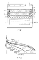
- FIG. 1 is a cross-sectional view schematically illustrating a direct methanol fuel cell according to an embodiment of the invention.
- a membrane-electrode assembly (MEA) 1 includes: a cathode made of a cathode catalyst layer 2 and a cathode gas diffusion layer 4; an anode made of an anode catalyst layer 3 and an anode gas diffusion layer 5; and a proton conductive electrolyte membrane 6 disposed between the cathode catalyst layer 2 and the anode catalyst layer 3.
- the cathode catalyst layer 2 is laminated on the cathode gas diffusion layer 4, while the anode catalyst layer 3 is laminated on the anode gas diffusion layer 5. While the cathode gas diffusion layer 4 serves to evenly feed an oxidant to the cathode catalyst layer 2, it also serves as a current collector of the cathode catalyst layer 2. On the other hand, while the anode gas diffusion layer 5 serves to evenly feed the fuel to the anode catalyst layer 3, it also serves as a current collector of the anode catalyst layer 3.
- a cathode conductive layer 7a and an anode conductive layer 7b are in contact with the cathode gas diffusion layer 4 and the anode gas diffusion layer 5, respectively.
- Porous layers made of a metal material such as gold may be used for the cathode conductive layer 7a and the anode conductive layer 7b, respectively.
- An example of the porous layers includes meshes.
- a rectangular frame-shaped cathode seal material 8a is positioned between the cathode conductive layer 7a and the proton conductive electrolyte membrane 6 and surrounds the cathode catalyst layer 2 and the cathode gas diffusion layer 4.
- a rectangular frame-shaped anode seal material 8b is positioned between the anode conductive layer 7b and the proton conductive membrane 6 and surrounds the anode catalyst layer 3 and the anode gas diffusion layer 5.
- the cathode seal material 8a and the anode seal material 8b are O-rings for preventing the fuel and oxidant from leaking from the membrane-electrode assembly 1.
- a liquid fuel tank 9 is disposed under the membrane-electrode assembly 1. Liquid methanol or an aqueous methanol solution is stored in the liquid fuel tank 9.
- a gas-liquid separation membrane 10, for example, as a fuel vaporization layer 10 is disposed so as to cover the opening of the liquid fuel tank 9.
- a resin frame 11 is disposed between the gas-liquid separation membrane 10 and the anode conductive layer 7b.
- the space surrounded by the frame 11 functions as a vaporized fuel storage chamber 12 (a so-called vapor pool) for temporarily storing the vaporized fuel diffused through the gas-liquid separation membrane 10.
- a vaporized fuel storage chamber 12 a so-called vapor pool
- An effect of suppressing the amount of permeated methanol by the vaporized fuel storage chamber 12 and the gas-liquid separation membrane 10 prevents a large amount of vaporized fuel from being supplied to the anode catalyst layer 3 at once, and cross-over of methanol may be suppressed from occurring.
- the frame 11 is a rectangular frame made of, for example, a thermoplastic polyester resin such as PET.
- a humectant plate 13 is laminated on the cathode conductive layer 7a laminated on the membrane-electrode assembly 1.
- the humectant plate 13 serves to prevent water generated in the cathode catalyst layer 2 from being vaporized while it serves as an auxiliary diffusion layer for facilitating uniform diffusion of the oxidant into the cathode catalyst layer 2 by uniformly introducing the oxidant into the cathode gas diffusion layer 4.
- the liquid fuel for example an aqueous methanol solution
- the liquid fuel tank 9 is vaporized, vaporized methanol and water diffuse in the gas-liquid separation membrane 10 and are temporarily stored in the vaporized fuel storage chamber 12.
- the vaporized fuel is then slowly supplied to the anode catalyst layer 3 by diffusion through the anode gas diffusion layer 5, and methanol is reformed by the internal reforming reaction shown by the following reaction formula (1): CH 3 OH + H 2 O ⁇ CO 2 + 6H + + 6e - (1)
- Water is generated in the cathode catalyst layer 2 by the reaction represented by the formula (2) as a power generation reaction proceeds. Since the ratio (L : L 0 ) of the total thickness L of the cathode catalyst layer 2 and the anode catalyst layer 3 to the thickness L 0 of the proton conductive membrane 6 is larger than 1:1 and 5:1 or less, the amount of generated water per unit volume may be increased. While the generated water arrives at the humectant plate 13 by diffusion through the cathode gas diffusion layer 4, vaporization of the water is blocked by the humectant plate 13. Accordingly, the amount of stored water in the cathode catalyst layer 2 may be increased by defining the ratio of thickness and by using the humectant plate. In addition, since the concentration of methanol in the liquid fuel is more than 50 mol% and no more than 100 mol%, the amount of water supplied from the fuel vaporization layer to the anode catalyst layer may be reduced.
- the invention is not restricted to the above-mentioned embodiment, and may be applied to any cases as long as the concentration of methanol in the liquid fuel is more than 50 mol% and no more than 100 mol%, and the ratio (L : L 0 ) of the total thickness L of the cathode catalyst layer 2 and the anode catalyst layer 3 to the thickness L 0 of the proton conductive membrane 6 is more than 1:1 and no more than 5:1.
- the fuel cell may have no humectant plate between the cathode gas diffusion layer and the surface layer.
- the paste obtained was applied to porous carbon paper as an anode gas diffusion layer to obtain an anode catalyst layer with a thickness of 160 ⁇ m (excluding the thickness of carbon paper).
- a solution of perfluorocarbon sulfonic acid, water and methoxypropanol were added to carbon black that retained a cathode catalyst (Pt), and a paste was prepared by dispersing the cathode catalyst-retaining carbon black.
- the paste obtained was applied to porous carbon paper as a cathode gas diffusion layer to obtain a cathode catalyst layer with a thickness of 140 ⁇ m (excluding the thickness of carbon paper).
- a perfluorocarbon sulfonic acid membrane (trade name: Nafion, manufactured by Du Pont) with a thickness of 50 ⁇ m and water content of 10 to 20% by weight was disposed between the anode catalyst layer and the cathode catalyst layer as a proton conductive electrolyte membrane, and a membrane-electrode assembly (MEA) was obtained by hot-pressing of the catalyst layers and membrane.
- MEA membrane-electrode assembly
- the ratio between the total thickness L of the cathode catalyst layer and the anode catalyst layer and the thickness L 0 of the proton conductive electrolyte membrane namely, the ratio (L : L 0 ) of the total thickness L to the thickness L 0 of the proton conductive electrolyte membrane, and the ratio between the thickness L 1 of the anode catalyst layer and the thickness L 2 of the cathode catalyst layer, namely, the ratio (L 1 : L 2 ) of the thickness L 1 of the anode catalyst layer to the thickness L 2 of the cathode catalyst layer, are shown in Table 1 below.
- a polyethylene porous film with a thickness of 500 ⁇ m, a gas permeability of 2 seconds/100 cm 3 (JIS P-8117) and a moisture permeability of 4000 g/m 2 ⁇ 24h (JIS L-1099 A-1) was prepared as a humectant plate.
- the frame 11 was made of PET with a thickness of 25 ⁇ m.
- a silicone rubber sheet with a thickness of 200 ⁇ m was prepared as a gas-liquid separation membrane.
- a direct methanol fuel cell of an internal vaporization type having the structure shown in FIG. 1 was assembled using the membrane-electrode assembly 1, humectant plate 13, frame 11 and gas-liquid separation membrane 10 obtained. At this time, pure methanol (2 mL) with a purity of 99.9% by weight was stored in the fuel tank.
- Direct methanol fuel cells of the internal vaporization type were assembled by the same method as described in Example 1, except that the thickness of each layer measured from the cross-dimensional photograph of the MEA obtained and the ratios of thickness (L : L 0 and L 1 : L 2 ) were changed as shown in Table 1.
- each layer was determined as shown in Table 1 by adjusting the thickness of coating on the carbon paper and the thickness of the perfluorocarbon sulfonic acid membrane before compressing.
- a direct methanol fuel cell of the internal vaporization type was assembled by the same method as described in Example 1, except that an aqueous methanol solution with a concentration of 10% by weight was stored in the fuel tank in place of pure methanol, and no humectant plate was disposed between the cathode diffusion layer and the surface layer.
- Example 1 100 80 1.25:1 48 3.8:1
- Example 2 65 50 1.3:1 30 3.8:1
- Example 3 65 50 1.3:1 48 2.4:1
- Example 4 50 50 1:1 30 3.3:1
- Example 5 45 50 0.9:1 30 3.2:1
- Example 6 115 90 1.3:1 48 4.2:1
- Example 7 70 50 1.3:1 80 1.5:1 Comparative Example 4 100 80 1.25:1 48 3.8:1 (methanol 20 wt%)
- the fuel cells in Examples 1 to 5 which have the ratio (L : L 0 ) of the total thickness L of the catalyst layers to the thickness L 0 of the proton conductive membrane of more than 1:1 and no more than 5:1, show a smaller voltage drop when the load current is increased and are excellent in time-dependent stability of the output power density, as compared with the fuel cells in Comparative Examples 1 and 2 having the ratio (L : L 0 ) of thickness out of the above-mentioned range and the fuel cell in Comparative Example 3 with a methanol concentration of 50 mol% or less.
- Example 1 to 5 a higher voltage was obtained by the fuel cells in Examples 1 to 4 having the ratio (L 1 : L 2 ) of the thickness L 1 of the anode catalyst layer to the thickness L 2 of the cathode catalyst layer in the range of 1:1 to 2:1 than the fuel cell in Example 5 having a smaller thickness L 1 of the anode catalyst layer than the thickness L 2 of the cathode catalyst layer, and the former fuel cells were superior in time-dependent stability of the output power density.
- Direct methanol fuel cells of the internal vaporization type were assembled by the same method as described in Example 1, except that the thickness of each layer measured from the cross-sectional photograph of the MEA obtained, the ratio (L : L 0 ) of thickness and the ratio (L 1 : L 2 ) of thickness were changed as shown in Table 1.
- each layer was determined as shown in Table 1 by controlling the thickness of coating on carbon paper and the thickness of the perfluorocarbon sulfonic acid membrane before compression of the membrane.
- a direct methanol fuel cell of the internal vaporization type was assembled by the same method as described in Example 1, except that an aqueous methanol solution with a concentration of 20% by weight was stored in the fuel tank in place of pure methanol, and no humectant plate was disposed between the cathode diffusion layer and the surface layer.
- FIG. 4 Current-voltage curves (I-V curves) were measured for the fuel cells obtained in Examples 6 and 7 and Comparative Example 4. The results are shown in FIG. 4. Power generation was preformed at room temperature under a constant load, and time-dependent changes of the power output at that time of the cell were measured. The results are shown in FIG. 5. In FIG. 5, the horizontal axis denotes the power generation time while the vertical axis denotes the output power density. The output power density is represented by a relative output power density when the maximum output power density in Example 1 is assumed to be 100. The results in Examples 1 to 5 and Comparative Examples 1 to 3 are also shown in FIGS. 4 and 5.
- the fuel cells of Examples 1 to 6 having the ratio (L : L 0 ) in the range of 2:1 to 5:1 showed a smaller voltage drop width when the current density was increased than the fuel cell in Example 7 having the ratio (L : L 0 ) of 1.5:1, and time-dependent stability of the output power density of the cells of Examples 1 to 6 was superior to that of the cell in Example 7.
- the invention is not directly restricted to the above-mentioned embodiments, and may be embodied by modifying the constituting elements in implementing the invention in the range not departing from the spirit of the invention.
- Various inventions may be constructed by appropriate combinations of a plurality of constituting elements disclosed in the embodiments. For example, some of the constituting elements may be deleted from the entire constituting elements shown in the embodiments, or constituting elements disclosed in different embodiments may be appropriately combined.
Abstract
A fuel cell using a liquid fuel containing methanol with a concentration of more than 50 mol% and no more than 100 mol%, the fuel cell includes a cathode catalyst layer (2), an anode catalyst layer (3) to which a vaporized component of the liquid fuel is supplied, and a proton conductive membrane (6) provided between the cathode catalyst layer (2) and the anode catalyst layer (3), wherein a ratio (L : L0) of a thickness L to a thickness L0 is more than 1:1 and no more than 5:1 assuming a total thickness of the cathode catalyst layer (2) and the anode catalyst layer (3) to be represented by L and a thickness of the proton conductive membrane (6) to be represented by L0.
Description
- The present invention relates to a fuel cell employing a system for feeding a vaporized fuel obtained by vaporizing a liquid fuel to an anode catalyst layer.
- In recent years, various electronic devices such as personal computers and cellular telephones have become compact as a result of developments in semiconductor technologies, and attempts are being made to use fuel cells in these compact devices. Fuel cells have an advantage that to generate electricity merely requires the supply of fuel and an oxidizer, and continuous electricity generation merely requires the fuel to be replenished. Therefore, they are very advantageous systems to power portable electronic devices if they can be compact. In particular, since a direct methanol fuel cell (DMFC) is able to directly obtain an electric current from methanol on an electrode catalyst using methanol having a high energy density as a fuel, the fuel cell has a potential to be miniaturized without using any reformers. DMFC is quite promising as a power source for small-sized devices since handling of the fuel is easier than a hydrogen gas fuel.
- Known methods for feeding the fuel to DMFC include a gas feed DMFC where the fuel is supplied into the fuel cell with a blower after vaporizing the liquid fuel, a liquid feed DMFC where the liquid fuel is directly supplied into the fuel cell with a pump, and an internal vaporization DMFC as disclosed in
Japanese Patent No. 3413111 - The internal vaporization DMFC disclosed in
Japanese Patent No. 3413111 Japanese Patent No. 3413111 - However, the internal vaporization DMFC disclosed in
Japanese Patent No. 3413111 - Accordingly, an object of the invention is to improve output power performance of a fuel cell provided with an anode catalyst layer to which a vaporized component of liquid fuel is supplied.
- According to an aspect of the present invention, there is provided a fuel cell comprising:
- a cathode catalyst layer;
- an anode catalyst layer to which a vaporized component of a liquid fuel is supplied; and
- a proton conductive membrane provided between the cathode catalyst layer and the anode catalyst layer,
- wherein the liquid fuel contains methanol with a concentration of more than 50 mol% and no more than 100 mol%, and a ratio (L : L0) of a thickness L to a thickness L0 is more than 1:1 and no more than 5:1 assuming a total thickness of the cathode catalyst layer and the anode catalyst layer to be represented by L and a thickness of the proton conductive membrane to be represented by L0.
- According to another aspect of the present invention, there is provided a fuel cell using a liquid fuel containing methanol with a concentration of more than 50 mol% and no more than 100 mol%, the fuel cell comprising:
- a cathode catalyst layer;
- an anode catalyst layer to which a vaporized component of the liquid fuel is supplied; and
- a proton conductive membrane provided between the cathode catalyst layer and the anode catalyst layer,
- wherein a ratio (L : L0) of a thickness L to a thickness L0 is more than 1:1 and no more than 5:1 assuming a total thickness of the cathode catalyst layer and the anode catalyst layer to be represented by L and a thickness of the proton conductive membrane to be represented by L0.
-
- FIG. 1 is a cross-sectional view schematically illustrating a direct methanol fuel cell according to an embodiment of the invention.
- FIG. 2 is a graph showing a relation between current density and cell voltage of direct methanol fuel cells according to Examples 1 to 5 and Comparative Examples 1 to 3.
- FIG. 3 is a graph showing time-dependent changes of output power density of the direct methanol fuel cells according to Examples 1 to 5 and Comparative Examples 1 to 3.
- FIG. 4 is a graph showing a relation between the current density and cell voltage of the direct methanol fuel cells according to Examples 1 to 7 and Comparative Examples 1 to 4.
- FIG. 5 is a graph showing time-dependent changes of the output power density of the direct methanol fuel cells according to Examples 1 to 7 and Comparative Examples 1 to 4.
- The inventors of the invention have found, through intensive studies, that output power performance and time-dependent stability of the output power of a fuel cell can be stabilized by satisfying the following conditions (a) and (b) in the fuel cell comprising a fuel vaporization layer for feeding gas components of liquid fuel to an anode catalyst layer. This is because the anode catalyst layer may be sufficiently hydrated with water in a cathode catalyst layer.
- (a) The concentration of methanol in the liquid fuel is controlled to be more than 50 mol% and 100 mol% or less.
- (b) The ratio (L : L0) between a total thickness L of the cathode catalyst layer and the anode catalyst layer and a thickness L0 of a proton conductive membrane, namely, the ratio (L : L0) of the total thickness L of the cathode catalyst layer and the anode catalyst layer to the thickness L0 of the proton conductive membrane, is adjusted to be more than 1:1 and 5:1 or less. The ratio (L : L0) denotes the proportion of the total thickness L when the thickness L0 of the proton conductive membrane is assumed to be 1.
- Controlling the concentration of methanol in the liquid fuel to be more than 50 mola and no more than 100 mol% permits the amount of water supplied to the anode catalyst layer though the fuel vaporization layer to be reduced or to be zero. On the other hand, while water is generated at the cathode catalyst layer by power generation, the ratio of thickness (L/L0) larger than 1:1 and 5:1 or less permits the amount of generation of water per unit volume to be increased at the cathode catalyst layer without causing the problem of cross-over of methanol.
- Defining the thickness ratio of the catalyst layers to the proton conductive membrane and methanol concentration as described above permits the amount of retention of water at the cathode catalyst layer to be larger than that at the anode catalyst layer. As a result, diffusion of water from the cathode catalyst layer to the anode catalyst layer may be facilitated by an osmotic phenomenon. Accordingly, since feed of water to the anode catalyst layer is improved as compared with feed of water to the anode catalyst layer only by the fuel vaporization layer, reaction resistance of the internal reforming reaction of the fuel may be reduced to improve the output power performance and time-dependent stability of the output power.
- Since water generated in the cathode catalyst layer is made available in the internal reforming reaction of the liquid fuel in the anode catalyst layer according to the invention, the burden of treatment such as discharge of water generated in the cathode catalyst layer out of the fuel cell may be reduced while no special structure for feeding water to the liquid fuel is needed. Therefore, the invention provides a fuel cell having a simple structure.
- In addition, a fuel having a high concentration which exceeds a stoichiometric ratio, which has been theoretically impossible to use, may be used according to the invention. Reduction of the size of a liquid fuel tank is also possible.
- The reason why the ratio of thickness (L : L0) is restricted within the above-mentioned range will be described in detail below. Since the amount of generation of water per unit volume at the cathode catalyst layer is insufficient when the ratio of thickness (L : L0) is 1:1 or less, the amount of retained water is deficient in the anode catalyst layer. On the other hand, cross-over of methanol tends to be caused when the ratio of thickness (L : L0) exceeds 5:1. Accordingly, the range of the ratio of thickness (L : L0) is more preferably in the range of 2:1 to 5:1, further preferably in the range of 2:1 to 4:1.
- The inventors of the invention have also found that the output power performance and time-dependent stability of the output of the fuel cell may be further improved by adjusting the ratio between the thickness L1 of the anode catalyst layer and the thickness L2 of the cathode catalyst layer, namely, the ratio (L1 : L2) of the thickness L1 of the anode catalyst layer to the thickness L2 of the cathode catalyst layer, in the range of 1:1 to 2:1. The ratio of thickness (L1 : L2) denotes the proportion of the thickness L1 of the anode catalyst layer when the thickness L2 of the cathode catalyst layer is assumed to be 1.
- Vaporization of water from the anode catalyst layer may be suppressed by adjusting the ratio of thickness (L1 : L2) to be 1:1 or more. Retention of water at the anode catalyst layer may be improved to consequently increase the amount of water miscible with methanol in the interface between the proton conductive membrane and the catalyst layer. This enables a stoichiometric relation of the reaction to be ensured while a catalyst layer binder susceptible to high concentration of methanol can be protected. However, over-voltage applied to the cathode increases when the ratio of thickness (L1 : L2) is larger than 2:1, and time-dependent deterioration of the catalyst at the cathode side and proton conductive membrane may be caused.
- For the above-mentioned reasons, output power performance and time-dependent stability of output may be further improved by adjusting the ratio of thickness (L1 : L2) in the range of 1:1 to 2:1.
- A more preferable range of the ratio of thickness (L1 : L2) is from 1:1 to 1.5:1.
- The cathode catalyst layer, another catalyst layer, proton conductive membrane, liquid fuel and fuel vaporization layer will be described below.
- Examples of the catalyst contained in the cathode catalyst layer and anode catalyst layer include pure metals of the platinum group elements (such as Pt, Ru, Rh, Ir, Os and Pt) and alloys containing the platinum group elements. While Pt-Ru alloys highly resistant to methanol and carbon monoxide are desirably used for the anode catalyst and platinum is desirably used for the cathode catalyst, the material is not restricted thereto. For example, a substance being active to redox of methanol and a substance being active to oxidation of proton with oxygen may be used for the anode catalyst and cathode catalyst, respectively.
- A supported catalyst using a conductive support such as a carbon material or a non-support catalyst may also be used.
- Examples of a proton conductive material contained in a proton conductive electrolyte membrane include, but are not limited to, fluorinated resins having sulfonic acid groups (for example perfluorosulfonic acid based polymers), hydrocarbon based resins having sulfonic acid groups, hydrocarbon based resins having sulfonic acid groups as well as imide groups or amino groups in the main chain, and inorganic materials such as tungstic acid and phosphorus wolframate.
- The proton conductive membrane containing the perfluorosulfonic acid based polymer is desirably used for improving water retention of the anode catalyst layer.
- An example of the perfluorosulfonic acid based polymer is a perfluorocarbon sulfonic acid polymer, which is a polymer produced by cross-linking or polymerization and exhibits various performance depending on the degree of substitution of the main chain with fluorine, degree of polymerization and the length of the side chain.
- The thickness of the proton conductive membrane is desirably 100 µm or less. This thickness permits diffusion of water from the cathode catalyst layer to the anode catalyst layer to be more facilitated to obtain a higher output power density. However, the thickness of the proton conductive electrolyte membrane is preferably in the range of 10 to 100 µm, since the strength of the electrolyte membrane may be reduced when the thickness of the proton conductive electrolyte membrane is less than 10 µm. A more preferable range of the thickness is from 10 to 80 µm.
- An aqueous methanol solution with a methanol concentration of more than 50 mol% and less than 100 mol%, or pure methanol (methanol concentration of 100 mol%) may be used for the liquid fuel. The purity of pure methanol is desirably in the range of 95% to 100% by weight.
- A gas-liquid separation membrane that is capable of permeating only a vaporized component of the liquid fuel but does not permeate the liquid fuel may be used as the fuel vaporization layer. The vaporized component of the liquid fuel as used herein refers to vaporized methanol when liquid methanol is used as the liquid fuel, while it refers to a mixed gas containing the vaporized components of methanol and water when the aqueous methanol solution is used as the liquid fuel. An example of the gas-liquid separation membrane is a silicone rubber sheet.
- The direct methanol fuel cell as an embodiment of the fuel cell according to the invention will be described hereinafter with reference to the drawings.
- FIG. 1 is a cross-sectional view schematically illustrating a direct methanol fuel cell according to an embodiment of the invention.
- As shown in FIG. 1, a membrane-electrode assembly (MEA) 1 includes: a cathode made of a
cathode catalyst layer 2 and a cathodegas diffusion layer 4; an anode made of ananode catalyst layer 3 and an anodegas diffusion layer 5; and a protonconductive electrolyte membrane 6 disposed between thecathode catalyst layer 2 and theanode catalyst layer 3. - The
cathode catalyst layer 2 is laminated on the cathodegas diffusion layer 4, while theanode catalyst layer 3 is laminated on the anodegas diffusion layer 5. While the cathodegas diffusion layer 4 serves to evenly feed an oxidant to thecathode catalyst layer 2, it also serves as a current collector of thecathode catalyst layer 2. On the other hand, while the anodegas diffusion layer 5 serves to evenly feed the fuel to theanode catalyst layer 3, it also serves as a current collector of theanode catalyst layer 3. Acathode conductive layer 7a and an anodeconductive layer 7b are in contact with the cathodegas diffusion layer 4 and the anodegas diffusion layer 5, respectively. Porous layers made of a metal material such as gold may be used for thecathode conductive layer 7a and the anodeconductive layer 7b, respectively. An example of the porous layers includes meshes. - A rectangular frame-shaped
cathode seal material 8a is positioned between thecathode conductive layer 7a and the protonconductive electrolyte membrane 6 and surrounds thecathode catalyst layer 2 and the cathodegas diffusion layer 4. On the other hand, a rectangular frame-shapedanode seal material 8b is positioned between the anodeconductive layer 7b and the protonconductive membrane 6 and surrounds theanode catalyst layer 3 and the anodegas diffusion layer 5. Thecathode seal material 8a and theanode seal material 8b are O-rings for preventing the fuel and oxidant from leaking from the membrane-electrode assembly 1. - A
liquid fuel tank 9 is disposed under the membrane-electrode assembly 1. Liquid methanol or an aqueous methanol solution is stored in theliquid fuel tank 9. A gas-liquid separation membrane 10, for example, as afuel vaporization layer 10 is disposed so as to cover the opening of theliquid fuel tank 9. - A
resin frame 11 is disposed between the gas-liquid separation membrane 10 and the anodeconductive layer 7b. The space surrounded by theframe 11 functions as a vaporized fuel storage chamber 12 (a so-called vapor pool) for temporarily storing the vaporized fuel diffused through the gas-liquid separation membrane 10. An effect of suppressing the amount of permeated methanol by the vaporizedfuel storage chamber 12 and the gas-liquid separation membrane 10 prevents a large amount of vaporized fuel from being supplied to theanode catalyst layer 3 at once, and cross-over of methanol may be suppressed from occurring. Theframe 11 is a rectangular frame made of, for example, a thermoplastic polyester resin such as PET. - A
humectant plate 13 is laminated on thecathode conductive layer 7a laminated on the membrane-electrode assembly 1. Asurface layer 15, on which a plurality ofair inlet ports 14 for introducing air as an oxidant are open, is laminated on thehumectant plate 13. Since thesurface layer 15 also serves to enhance adhesiveness of the stack including the membrane-electrode assembly 1 by pressurizing the stack, the surface layer is made of a metal such as SUS304. Thehumectant plate 13 serves to prevent water generated in thecathode catalyst layer 2 from being vaporized while it serves as an auxiliary diffusion layer for facilitating uniform diffusion of the oxidant into thecathode catalyst layer 2 by uniformly introducing the oxidant into the cathodegas diffusion layer 4. - According to the direct methanol fuel cell having the above-mentioned structure, the liquid fuel (for example an aqueous methanol solution) in the
liquid fuel tank 9 is vaporized, vaporized methanol and water diffuse in the gas-liquid separation membrane 10 and are temporarily stored in the vaporizedfuel storage chamber 12. The vaporized fuel is then slowly supplied to theanode catalyst layer 3 by diffusion through the anodegas diffusion layer 5, and methanol is reformed by the internal reforming reaction shown by the following reaction formula (1):
CH3OH + H2O → CO2 + 6H+ + 6e- (1)
- When pure methanol is used as the liquid fuel, no water is supplied from the fuel vaporization layer. Consequently, water generated by the oxidation reaction of methanol mingled into the
cathode catalyst layer 2, or water in the protonconductive electrolyte membrane 6 reacts with methanol to induce the internal reforming reaction represented by the formula (1). Alternatively, the internal reforming reaction occurs by a different reaction mechanism using no water which is not dependent on the formula (1). - Protons (H+) generated by the internal reforming reaction diffuse through the proton
conductive electrolyte membrane 6 and arrive at thecathode catalyst layer 3. On the other hand, air introduced from theair inlet port 14 on thesurface layer 15 is supplied to thecathode catalyst layer 2 by diffusion through thehumectant plate 13 and cathodegas diffusion layer 4. Water is generated in thecathode catalyst layer 2 by the reaction represented by the following formula (2):
(3/2)O2 + 6H+ + 6e- → 3H2O (2)
- Water is generated in the
cathode catalyst layer 2 by the reaction represented by the formula (2) as a power generation reaction proceeds. Since the ratio (L : L0) of the total thickness L of thecathode catalyst layer 2 and theanode catalyst layer 3 to the thickness L0 of the protonconductive membrane 6 is larger than 1:1 and 5:1 or less, the amount of generated water per unit volume may be increased. While the generated water arrives at thehumectant plate 13 by diffusion through the cathodegas diffusion layer 4, vaporization of the water is blocked by thehumectant plate 13. Accordingly, the amount of stored water in thecathode catalyst layer 2 may be increased by defining the ratio of thickness and by using the humectant plate. In addition, since the concentration of methanol in the liquid fuel is more than 50 mol% and no more than 100 mol%, the amount of water supplied from the fuel vaporization layer to the anode catalyst layer may be reduced. - Consequently, since the amount of retained water in the
cathode catalyst layer 2 becomes larger than that in theanode catalyst layer 3 in accordance with progress of the power generation reaction, a reaction for transferring water generated in thecathode catalyst layer 2 to theanode catalyst layer 3 through the protonconductive electrolyte membrane 6 is accelerated by an osmosis phenomenon. This enables the water feed speed to the anode catalyst layer to be improved as compared with the case when feed of water is entirely dependent on the fuel vaporization layer, and the internal reforming reaction of methanol represented by the formula (1) may be facilitated. Accordingly, the output power density may be increased while the high output density may be maintained for a long period of time. - The invention is not restricted to the above-mentioned embodiment, and may be applied to any cases as long as the concentration of methanol in the liquid fuel is more than 50 mol% and no more than 100 mol%, and the ratio (L : L0) of the total thickness L of the
cathode catalyst layer 2 and theanode catalyst layer 3 to the thickness L0 of the protonconductive membrane 6 is more than 1:1 and no more than 5:1. For example, the fuel cell may have no humectant plate between the cathode gas diffusion layer and the surface layer. - Examples of the invention will be described in detail hereinafter with reference to the drawings.
- A solution of perfluorocarbon sulfonic acid, water and methoxypropanol were added to carbon black that retained an anode catalyst (Pt : Ru = 1:1), and a paste was prepared by dispersing the anode catalyst-retaining carbon black. The paste obtained was applied to porous carbon paper as an anode gas diffusion layer to obtain an anode catalyst layer with a thickness of 160 µm (excluding the thickness of carbon paper).
- A solution of perfluorocarbon sulfonic acid, water and methoxypropanol were added to carbon black that retained a cathode catalyst (Pt), and a paste was prepared by dispersing the cathode catalyst-retaining carbon black. The paste obtained was applied to porous carbon paper as a cathode gas diffusion layer to obtain a cathode catalyst layer with a thickness of 140 µm (excluding the thickness of carbon paper).
- A perfluorocarbon sulfonic acid membrane (trade name: Nafion, manufactured by Du Pont) with a thickness of 50 µm and water content of 10 to 20% by weight was disposed between the anode catalyst layer and the cathode catalyst layer as a proton conductive electrolyte membrane, and a membrane-electrode assembly (MEA) was obtained by hot-pressing of the catalyst layers and membrane. The thickness of each layer was calculated from a cross-sectional photograph of the MEA thus obtained. The thickness of the anode catalyst layer was 100 µm excluding the thickness of carbon paper, the thickness of the cathode catalyst layer was 80 µm excluding the thickness of carbon paper, and the thickness of the proton conductive electrolyte membrane was 48 µm.
- The ratio between the total thickness L of the cathode catalyst layer and the anode catalyst layer and the thickness L0 of the proton conductive electrolyte membrane, namely, the ratio (L : L0) of the total thickness L to the thickness L0 of the proton conductive electrolyte membrane, and the ratio between the thickness L1 of the anode catalyst layer and the thickness L2 of the cathode catalyst layer, namely, the ratio (L1 : L2) of the thickness L1 of the anode catalyst layer to the thickness L2 of the cathode catalyst layer, are shown in Table 1 below.
- A polyethylene porous film with a thickness of 500 µm, a gas permeability of 2 seconds/100 cm3 (JIS P-8117) and a moisture permeability of 4000 g/m2·24h (JIS L-1099 A-1) was prepared as a humectant plate.
- The
frame 11 was made of PET with a thickness of 25 µm. A silicone rubber sheet with a thickness of 200 µm was prepared as a gas-liquid separation membrane. - A direct methanol fuel cell of an internal vaporization type having the structure shown in FIG. 1 was assembled using the membrane-
electrode assembly 1,humectant plate 13,frame 11 and gas-liquid separation membrane 10 obtained. At this time, pure methanol (2 mL) with a purity of 99.9% by weight was stored in the fuel tank. - Direct methanol fuel cells of the internal vaporization type were assembled by the same method as described in Example 1, except that the thickness of each layer measured from the cross-dimensional photograph of the MEA obtained and the ratios of thickness (L : L0 and L1 : L2) were changed as shown in Table 1.
- The thickness of each layer was determined as shown in Table 1 by adjusting the thickness of coating on the carbon paper and the thickness of the perfluorocarbon sulfonic acid membrane before compressing.
- A direct methanol fuel cell of the internal vaporization type was assembled by the same method as described in Example 1, except that an aqueous methanol solution with a concentration of 10% by weight was stored in the fuel tank in place of pure methanol, and no humectant plate was disposed between the cathode diffusion layer and the surface layer.
Table 1 Thickness of anode catalyst layer (µm) Thickness of cathode catalyst layer (µm) Ratio of thickness of anode catalyst layer to cathode catalyst layer (L1:L2) Thickness of proton conductive membrane (µm) Ratio of total thickness of catalyst layers to thickness of proton conductive membrane (L:L0) Example 1 100 80 1.25:1 48 3.8:1 Example 2 65 50 1.3:1 30 3.8:1 Example 3 65 50 1.3:1 48 2.4:1 Example 4 50 50 1:1 30 3.3:1 Example 5 45 50 0.9:1 30 3.2:1 Comparative Example 1 40 50 0.8:1 100 0.9:1 Comparative Example 2 100 80 1.25 30 6.0:1 Comparative Example 3 100 80 1.25:1 48 3.8:1 Example 6 115 90 1.3:1 48 4.2:1 Example 7 70 50 1.3:1 80 1.5:1 Comparative Example 4 100 80 1.25:1 48 3.8:1
(methanol 20 wt%) - Current-voltage curves (I-V curves) were measured for the fuel cells obtained in Examples 1 to 5 and Comparative Examples 1 to 3. Time-dependent changes of the output power of the cell were also measured by generating electricity at room temperature under a constant load. The horizontal axis denotes the power generation time while the vertical axis denotes the output power density. The output power density is represented by a relative output power density assuming that the maximum output power density in Example 1 is 100.
- It is evident from FIGS. 2 and 3 that the fuel cells in Examples 1 to 5, which have the ratio (L : L0) of the total thickness L of the catalyst layers to the thickness L0 of the proton conductive membrane of more than 1:1 and no more than 5:1, show a smaller voltage drop when the load current is increased and are excellent in time-dependent stability of the output power density, as compared with the fuel cells in Comparative Examples 1 and 2 having the ratio (L : L0) of thickness out of the above-mentioned range and the fuel cell in Comparative Example 3 with a methanol concentration of 50 mol% or less.
- Of Examples 1 to 5, a higher voltage was obtained by the fuel cells in Examples 1 to 4 having the ratio (L1 : L2) of the thickness L1 of the anode catalyst layer to the thickness L2 of the cathode catalyst layer in the range of 1:1 to 2:1 than the fuel cell in Example 5 having a smaller thickness L1 of the anode catalyst layer than the thickness L2 of the cathode catalyst layer, and the former fuel cells were superior in time-dependent stability of the output power density.
- Direct methanol fuel cells of the internal vaporization type were assembled by the same method as described in Example 1, except that the thickness of each layer measured from the cross-sectional photograph of the MEA obtained, the ratio (L : L0) of thickness and the ratio (L1 : L2) of thickness were changed as shown in Table 1.
- The thickness of each layer was determined as shown in Table 1 by controlling the thickness of coating on carbon paper and the thickness of the perfluorocarbon sulfonic acid membrane before compression of the membrane.
- A direct methanol fuel cell of the internal vaporization type was assembled by the same method as described in Example 1, except that an aqueous methanol solution with a concentration of 20% by weight was stored in the fuel tank in place of pure methanol, and no humectant plate was disposed between the cathode diffusion layer and the surface layer.
- Current-voltage curves (I-V curves) were measured for the fuel cells obtained in Examples 6 and 7 and Comparative Example 4. The results are shown in FIG. 4. Power generation was preformed at room temperature under a constant load, and time-dependent changes of the power output at that time of the cell were measured. The results are shown in FIG. 5. In FIG. 5, the horizontal axis denotes the power generation time while the vertical axis denotes the output power density. The output power density is represented by a relative output power density when the maximum output power density in Example 1 is assumed to be 100. The results in Examples 1 to 5 and Comparative Examples 1 to 3 are also shown in FIGS. 4 and 5.
- It is evident from FIGS. 4 and 5 that the fuel cells in Examples 6 and 7, which have a ratio (L : L0) of the total thickness L of the catalyst layers to the thickness L0 of the proton conductive membrane of larger than 1:1 and 5:1 or less, show gentle voltage drop against increase of the current density as compared with the fuel cells in Comparative Examples 1 to 4, and that time-dependent stability of the output power density of the former cells is superior to the latter cells in Comparative Examples 1 to 4.
- When the methanol concentration of the fuel cell was 50 mol% or less, the voltage drop width at the time of increasing current density was larger in the fuel cells shown in Comparative Examples 3 and 4 than the fuel cells shown in Examples 1 to 7 even when the ratio (L : L0) was more than 1:1 and no more than 5:1. The initial output power density of the fuel cells in Comparative Examples 3 and 4 were lower than that of the fuel cells in Examples 1 to 7.
- Of the fuel cells in Examples 1 to 7, the fuel cells of Examples 1 to 6 having the ratio (L : L0) in the range of 2:1 to 5:1 showed a smaller voltage drop width when the current density was increased than the fuel cell in Example 7 having the ratio (L : L0) of 1.5:1, and time-dependent stability of the output power density of the cells of Examples 1 to 6 was superior to that of the cell in Example 7.
- The invention is not directly restricted to the above-mentioned embodiments, and may be embodied by modifying the constituting elements in implementing the invention in the range not departing from the spirit of the invention. Various inventions may be constructed by appropriate combinations of a plurality of constituting elements disclosed in the embodiments. For example, some of the constituting elements may be deleted from the entire constituting elements shown in the embodiments, or constituting elements disclosed in different embodiments may be appropriately combined.
Claims (9)
- A fuel cell using a liquid fuel containing methanol with a concentration of more than 50 mol% and no more than 100 mol%, the fuel cell comprising:a cathode catalyst layer;an anode catalyst layer to which a vaporized component of the liquid fuel is supplied; anda proton conductive membrane provided between the cathode catalyst layer and the anode catalyst layer,wherein a ratio (L : L0) of a thickness L to a thickness L0 is more than 1:1 and no more than 5:1 assuming a total thickness of the cathode catalyst layer and the anode catalyst layer to be represented by L and a thickness of the proton conductive membrane to be represented by L0.
- The fuel cell according to claim 1, wherein the ratio (L : L0) of the thickness L to the thickness L0 is 2:1 or more and 5:1 or less.
- The fuel cell according to claim 1, wherein the ratio (L : L0) of the thickness L to the thickness L0 is 2:1 or more and 4:1 or less.
- The fuel cell according to claim 1, wherein a ratio (L1 : L2) of a thickness L1 to a thickness L2 is in the range of 1:1 to 2:1 when a thickness of the anode catalyst layer is represented by L1 and a thickness of the cathode catalyst layer is represented by L2.
- The fuel cell according to claim 1, wherein the ratio (L1 : L2) of the thickness L1 to the thickness L2 is in the range of 1:1 to 1.5:1.
- The fuel cell according to any one of claims 1 to 5, wherein the proton conductive membrane contains a perfluorosulfonic acid based polymer.
- The fuel cell according to any one of claims 1 to 5, wherein the proton conductive membrane has a thickness of 100 µm or less.
- The fuel cell according to any one of claims 1 to 5, wherein the proton conductive membrane has a thickness in the range of 10 to 100 µm.
- The fuel cell according to any one of claims 1 to 5, wherein the proton conductive membrane has a thickness in the range of 10 to 80 µm.
Applications Claiming Priority (2)
| Application Number | Priority Date | Filing Date | Title |
|---|---|---|---|
| JP2005100340 | 2005-03-31 | ||
| PCT/JP2006/306939 WO2006106969A1 (en) | 2005-03-31 | 2006-03-31 | Fuel cell |
Publications (2)
| Publication Number | Publication Date |
|---|---|
| EP1883128A1 true EP1883128A1 (en) | 2008-01-30 |
| EP1883128A4 EP1883128A4 (en) | 2011-06-29 |
Family
ID=37073519
Family Applications (1)
| Application Number | Title | Priority Date | Filing Date |
|---|---|---|---|
| EP06730887A Withdrawn EP1883128A4 (en) | 2005-03-31 | 2006-03-31 | Fuel cell |
Country Status (6)
| Country | Link |
|---|---|
| US (1) | US20080020263A1 (en) |
| EP (1) | EP1883128A4 (en) |
| JP (1) | JPWO2006106969A1 (en) |
| KR (1) | KR100909521B1 (en) |
| CN (1) | CN101151754B (en) |
| WO (1) | WO2006106969A1 (en) |
Families Citing this family (5)
| Publication number | Priority date | Publication date | Assignee | Title |
|---|---|---|---|---|
| US7491456B2 (en) * | 2003-03-28 | 2009-02-17 | Kyocera Corporation | Fuel cell assembly and electricity generation unit used in same |
| DE602005025749D1 (en) * | 2004-04-28 | 2011-02-17 | Nissan Motor | MEMBRANE ELECTRODE ASSEMBLY FOR A FUEL CELL AND FUEL CELL THEREFOR |
| DE102007014046B4 (en) * | 2007-03-23 | 2011-07-28 | Fraunhofer-Gesellschaft zur Förderung der angewandten Forschung e.V., 80686 | Fuel cell and method for its production |
| JP5262168B2 (en) * | 2008-02-18 | 2013-08-14 | トヨタ自動車株式会社 | Manufacturing method of membrane-electrode assembly for fuel cell |
| DE102018200687A1 (en) * | 2018-01-17 | 2019-07-18 | Audi Ag | Cascaded fuel cell stack and fuel cell system |
Citations (8)
| Publication number | Priority date | Publication date | Assignee | Title |
|---|---|---|---|---|
| JP2000106201A (en) * | 1998-09-30 | 2000-04-11 | Toshiba Corp | Fuel cell |
| JP2001076742A (en) * | 1999-09-01 | 2001-03-23 | Asahi Glass Co Ltd | Solid polymer fuel cell |
| JP2002015742A (en) * | 2000-06-30 | 2002-01-18 | Toshiba Corp | Fuel cell and proton conducting material for fuel cell |
| US20020187374A1 (en) * | 2001-05-02 | 2002-12-12 | Takashi Yamauchi | Fuel cell power generating apparatus, and operating method and combined battery of fuel cell power generating apparatus |
| WO2003081701A1 (en) * | 2000-10-18 | 2003-10-02 | General Motors Corporation | Methods of preparing membrane electrode assemblies |
| JP2004319389A (en) * | 2003-04-18 | 2004-11-11 | Matsushita Electric Ind Co Ltd | Fuel cell system |
| WO2005034274A2 (en) * | 2003-09-16 | 2005-04-14 | The Gillette Company | Enhanced fuel delivery for direct methanol fuel cells |
| WO2005106994A1 (en) * | 2004-04-28 | 2005-11-10 | Nissan Motor Co., Ltd. | Membrane-electrode assembly for fuel cell and fuel cell using same |
Family Cites Families (2)
| Publication number | Priority date | Publication date | Assignee | Title |
|---|---|---|---|---|
| JP2002184414A (en) * | 2000-12-15 | 2002-06-28 | Asahi Glass Co Ltd | Method of manufacturing gas diffusion electrode and method of manufacturing solid polymer fuel cell |
| US20040258975A1 (en) * | 2003-05-05 | 2004-12-23 | Extrand Charles W. | Fuel cell component with lyophilic surface |
-
2006
- 2006-03-31 JP JP2007511202A patent/JPWO2006106969A1/en not_active Abandoned
- 2006-03-31 EP EP06730887A patent/EP1883128A4/en not_active Withdrawn
- 2006-03-31 WO PCT/JP2006/306939 patent/WO2006106969A1/en active Application Filing
- 2006-03-31 KR KR1020077021835A patent/KR100909521B1/en not_active IP Right Cessation
- 2006-03-31 CN CN2006800101133A patent/CN101151754B/en not_active Expired - Fee Related
-
2007
- 2007-09-28 US US11/863,725 patent/US20080020263A1/en not_active Abandoned
Patent Citations (8)
| Publication number | Priority date | Publication date | Assignee | Title |
|---|---|---|---|---|
| JP2000106201A (en) * | 1998-09-30 | 2000-04-11 | Toshiba Corp | Fuel cell |
| JP2001076742A (en) * | 1999-09-01 | 2001-03-23 | Asahi Glass Co Ltd | Solid polymer fuel cell |
| JP2002015742A (en) * | 2000-06-30 | 2002-01-18 | Toshiba Corp | Fuel cell and proton conducting material for fuel cell |
| WO2003081701A1 (en) * | 2000-10-18 | 2003-10-02 | General Motors Corporation | Methods of preparing membrane electrode assemblies |
| US20020187374A1 (en) * | 2001-05-02 | 2002-12-12 | Takashi Yamauchi | Fuel cell power generating apparatus, and operating method and combined battery of fuel cell power generating apparatus |
| JP2004319389A (en) * | 2003-04-18 | 2004-11-11 | Matsushita Electric Ind Co Ltd | Fuel cell system |
| WO2005034274A2 (en) * | 2003-09-16 | 2005-04-14 | The Gillette Company | Enhanced fuel delivery for direct methanol fuel cells |
| WO2005106994A1 (en) * | 2004-04-28 | 2005-11-10 | Nissan Motor Co., Ltd. | Membrane-electrode assembly for fuel cell and fuel cell using same |
Non-Patent Citations (1)
| Title |
|---|
| See also references of WO2006106969A1 * |
Also Published As
| Publication number | Publication date |
|---|---|
| KR20070107149A (en) | 2007-11-06 |
| EP1883128A4 (en) | 2011-06-29 |
| WO2006106969A1 (en) | 2006-10-12 |
| CN101151754B (en) | 2010-04-14 |
| CN101151754A (en) | 2008-03-26 |
| JPWO2006106969A1 (en) | 2008-09-25 |
| US20080020263A1 (en) | 2008-01-24 |
| KR100909521B1 (en) | 2009-07-27 |
Similar Documents
| Publication | Publication Date | Title |
|---|---|---|
| TWI281762B (en) | Fuel cell | |
| EP1758188A1 (en) | Fuel cell | |
| US7704629B2 (en) | Direct oxidation fuel cells with improved cathode gas diffusion media for low air stoichiometry operation | |
| EP1863111A1 (en) | Fuel cell | |
| US20090042090A1 (en) | Fuel cell | |
| EP1883128A1 (en) | Fuel cell | |
| US7638223B2 (en) | Fuel cell | |
| US20110275003A1 (en) | Fuel cell | |
| JP2008293705A (en) | Membrane-electrode assembly, and fuel cell | |
| TW200836394A (en) | Fuel cell | |
| JPWO2008068886A1 (en) | Fuel cell | |
| US7749640B2 (en) | Fuel Cell | |
| JP2011096468A (en) | Fuel cell | |
| US8278001B2 (en) | Low-porosity anode diffusion media for high concentration direct methanol fuel cells and method of making | |
| WO2011052650A1 (en) | Fuel cell | |
| WO2007116692A1 (en) | Fuel cell container, container for electronic device having fuel cell mounted thereon and fuel cell provided with container | |
| JP2007080658A (en) | Fuel cell | |
| JP2009038014A (en) | Fuel cell and manufacturing method of fuel cell | |
| JP2011096467A (en) | Fuel cell | |
| JP2011129432A (en) | Oxygen-supplying device of fuel cell |
Legal Events
| Date | Code | Title | Description |
|---|---|---|---|
| PUAI | Public reference made under article 153(3) epc to a published international application that has entered the european phase |
Free format text: ORIGINAL CODE: 0009012 |
|
| 17P | Request for examination filed |
Effective date: 20071001 |
|
| AK | Designated contracting states |
Kind code of ref document: A1 Designated state(s): DE |
|
| DAX | Request for extension of the european patent (deleted) | ||
| RBV | Designated contracting states (corrected) |
Designated state(s): DE |
|
| A4 | Supplementary search report drawn up and despatched |
Effective date: 20110531 |
|
| STAA | Information on the status of an ep patent application or granted ep patent |
Free format text: STATUS: THE APPLICATION HAS BEEN WITHDRAWN |
|
| 18W | Application withdrawn |
Effective date: 20110826 |