EP1882872A1 - Waterproof structure for portion where members are tightened with screw - Google Patents
Waterproof structure for portion where members are tightened with screw Download PDFInfo
- Publication number
- EP1882872A1 EP1882872A1 EP06732666A EP06732666A EP1882872A1 EP 1882872 A1 EP1882872 A1 EP 1882872A1 EP 06732666 A EP06732666 A EP 06732666A EP 06732666 A EP06732666 A EP 06732666A EP 1882872 A1 EP1882872 A1 EP 1882872A1
- Authority
- EP
- European Patent Office
- Prior art keywords
- screw
- flat head
- insertion hole
- ring
- waterproof structure
- Prior art date
- Legal status (The legal status is an assumption and is not a legal conclusion. Google has not performed a legal analysis and makes no representation as to the accuracy of the status listed.)
- Withdrawn
Links
Images


Classifications
-
- F—MECHANICAL ENGINEERING; LIGHTING; HEATING; WEAPONS; BLASTING
- F16—ENGINEERING ELEMENTS AND UNITS; GENERAL MEASURES FOR PRODUCING AND MAINTAINING EFFECTIVE FUNCTIONING OF MACHINES OR INSTALLATIONS; THERMAL INSULATION IN GENERAL
- F16B—DEVICES FOR FASTENING OR SECURING CONSTRUCTIONAL ELEMENTS OR MACHINE PARTS TOGETHER, e.g. NAILS, BOLTS, CIRCLIPS, CLAMPS, CLIPS OR WEDGES; JOINTS OR JOINTING
- F16B43/00—Washers or equivalent devices; Other devices for supporting bolt-heads or nuts
- F16B43/001—Washers or equivalent devices; Other devices for supporting bolt-heads or nuts for sealing or insulation
-
- F—MECHANICAL ENGINEERING; LIGHTING; HEATING; WEAPONS; BLASTING
- F16—ENGINEERING ELEMENTS AND UNITS; GENERAL MEASURES FOR PRODUCING AND MAINTAINING EFFECTIVE FUNCTIONING OF MACHINES OR INSTALLATIONS; THERMAL INSULATION IN GENERAL
- F16B—DEVICES FOR FASTENING OR SECURING CONSTRUCTIONAL ELEMENTS OR MACHINE PARTS TOGETHER, e.g. NAILS, BOLTS, CIRCLIPS, CLAMPS, CLIPS OR WEDGES; JOINTS OR JOINTING
- F16B35/00—Screw-bolts; Stay-bolts; Screw-threaded studs; Screws; Set screws
- F16B35/04—Screw-bolts; Stay-bolts; Screw-threaded studs; Screws; Set screws with specially-shaped head or shaft in order to fix the bolt on or in an object
- F16B35/06—Specially-shaped heads
-
- F—MECHANICAL ENGINEERING; LIGHTING; HEATING; WEAPONS; BLASTING
- F16—ENGINEERING ELEMENTS AND UNITS; GENERAL MEASURES FOR PRODUCING AND MAINTAINING EFFECTIVE FUNCTIONING OF MACHINES OR INSTALLATIONS; THERMAL INSULATION IN GENERAL
- F16B—DEVICES FOR FASTENING OR SECURING CONSTRUCTIONAL ELEMENTS OR MACHINE PARTS TOGETHER, e.g. NAILS, BOLTS, CIRCLIPS, CLAMPS, CLIPS OR WEDGES; JOINTS OR JOINTING
- F16B5/00—Joining sheets or plates, e.g. panels, to one another or to strips or bars parallel to them
- F16B5/02—Joining sheets or plates, e.g. panels, to one another or to strips or bars parallel to them by means of fastening members using screw-thread
-
- Y—GENERAL TAGGING OF NEW TECHNOLOGICAL DEVELOPMENTS; GENERAL TAGGING OF CROSS-SECTIONAL TECHNOLOGIES SPANNING OVER SEVERAL SECTIONS OF THE IPC; TECHNICAL SUBJECTS COVERED BY FORMER USPC CROSS-REFERENCE ART COLLECTIONS [XRACs] AND DIGESTS
- Y10—TECHNICAL SUBJECTS COVERED BY FORMER USPC
- Y10S—TECHNICAL SUBJECTS COVERED BY FORMER USPC CROSS-REFERENCE ART COLLECTIONS [XRACs] AND DIGESTS
- Y10S411/00—Expanded, threaded, driven, headed, tool-deformed, or locked-threaded fastener
- Y10S411/915—Bolt having packing joint
Definitions
- the present invention relates to a waterproof structure for a portion where members are tightened with a screw.
- FIG. 4 shows an example of a conventional waterproof structure for a portion where members are tightened with a screw.
- FIG. 4 shows a state of a tightening section where a first member 10 and a second member 11 are fastened with a bolt 12, the tightening section being cut out by a plane passing through a central axis of the bolt 12.
- a screw hole 10a with a bottom is provided, and in the second member 11, a screw insertion hole 11a is provided.
- the second member 11 is fastened to the first member 10 by screwing the bolt 12 which passes through the screw insertion hole 11a into the screw hole 10a with a bottom.
- FIG. 4 exaggeratedly shows a state in a larger scale before the packing 14 is deformed.
- a ring-like packing 14 having a rectangular cross-section made of rubber is fitted in a dent of the spacer 13 made of metal and placed on the screw insertion hole 11a of the second member 11 mounted on the first member 10, and the bolt 12 is inserted into the packing 14 to be tightly screwed into the screw hole 10a with a bottom.
- a lower surface of the spacer 13 is pressed against an upper surface of the second member 11 by tightening up the bolt 12, and further the packing 14 is compressed and pressed against an inner surface of the spacer 13, an outer surface of the bolt 12 and the upper surface of the second member 11, providing a waterproof property.
- the packing 14 gets entangled with the screw portion of the bolt 12 in a process of tightening the bolt 12, the spacer 13 and the packing 14 are rotated together with the bolt 12, so that there arises a problem that the packing 14 is likely to be deformed.
- the upper surface of the second member 11 has to be a horizontal surface. Then, because a head of the bolt 12 is mounted on the upper surface of the second member 11, the spacer 13 and the head of the bolt are protruded from the upper surface of the second member 11, presenting a problem of requiring a larger, necessary space.
- a first boss 33 is provided in a front case 31 in a protruding manner toward a rear case 41, and a second boss 43 is provided in a protruding manner in the rear case 41 to be opposite to the first boss 33.
- a through hole 44 is made into the second boss 43 to insert a fixing screw 55 thereinto, and a hole 34 with a bottom is made into the first boss 33 to screw the fixing screw 55 thereto.
- an annular groove 45 coaxial with the through hole 44 is formed in a surface of the second boss 43 opposite to the first boss 33, and an O-ring 46 is positioned in this annular groove 45.
- annular projection 35 is formed to be opposite to the annular groove 45. Then, when the front case 31 and the rear case 41 are fitted in each other, the annular projection 35 is arranged to press the O-ring 46.
- the present invention was made in view of the points described above, and an object thereof is to provide a waterproof structure for a portion where members are tightened with a screw, not damaging the members and allowing for repeated use, with a necessary space not being enlarged.
- a waterproof structure for a portion where members are tightened with a screw is a waterproof structure for a tightening section where a first member having a screw hole with a bottom and a second member having a screw insertion hole with a screw that is inserted into the screw insertion hole and screwed to the screw hole, the waterproof structure being configured in such a way that the screw is a flat head screw, an annular groove coaxial with a recessed circular conical surface is provided in an outer surface of a spacer fitted in the screw insertion hole, having an insertion hole, in which the recessed circular conical surface is formed to be in surface contact with a circular conical surface of a head of the flat head screw, an O-ring is fitted in the annular groove, the spacer is placed between the first member and the second member, and the O-ring is pressed against an inner surface of the annular groove and a surface of the screw insertion hole of the second member by tightening up the flat head screw.
- the surface of the second member against which the O-ring is pressed is a circular conical surface coaxial with the flat head screw.
- the surface of the second member against which the O-ring is pressed is a plane surface orthogonal to a central axis of the flat head screw.
- the surface of the second member against which the O-ring is pressed is a cylindrical surface coaxial with the flat head screw.
- the O-ring is pressed by the surface not to be damaged, enabling repeated use. Further, the head of the flat head screw is put in the screw insertion hole of the second member, therefore the head of the screw is not protruded above the second member, eliminating enlargement of a necessary space.
- FIG. 1 is a partially cut away, perspective view illustrating a waterproof structure for a portion where members are tightened, of a first embodiment according to the present invention, illustrating a tightening section where a first member 1 and a second member 2 are fastened with a flat head screw 4, the tightening section being cut out with a plane passing through a central axis of the flat head screw 4.
- a screw hole 1a with a bottom is provided, and in the second member 2, a screw insertion hole 2a is provided.
- the second member 2 is fastened to the first member 1 by screwing the flat head screw 4 which passes through the screw insertion hole 2a into the screw hole 1a with a bottom.
- a spacer 3 and an O-ring 5 are placed between the flat head screw 4 and the second member 2.
- a recessed circular conical surface 3a is formed to be in surface contact with a circular conical surface of a head of the flat head screw 4, and in the outside of the spacer 3, an annular groove 3b is formed.
- the spacer 3 having the O-ring 5 fitted in the annular groove 3b is fitted in a circular conical surface 2b of the second member 2. Then, the flat head screw 4 is inserted into the recessed circular conical surface 3a of the spacer 3 and an insertion hole communicating with it, and screwed into the screw hole 1a with a bottom of the first member 1.
- the second member 2 is fastened to the first member 1, and at this time, a waterproof property between the spacer 3 and the second member 2 is accomplished by the O-ring 5 pressed against these members. Also, because the circular conical surface of the head of the flat head screw 4 and the recessed circular conical surface 3a are aligned to be completely coaxial with each other when the O-ring 5 is elastically deformed, a waterproof property is accomplished by ensuring a tight surface contact.
- the O-ring 5 is not damaged due to being pressed by the surface, allowing for repeated use. Further, because the head of the flat head screw 4 is put in the screw insertion hole 2a of the second member 2, the head of the flat head screw 4 is not protruded above the second member 2 and a necessary space is not enlarged.
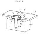
- FIG. 2 is a partially cut away, perspective view illustrating a waterproof structure for a portion where members are tightened, of a second embodiment according to the present invention, illustrating a tightening section where a first member 1 and a second member 6 are fastened with a flat head screw 4, the tightening section being cut out with a plane passing through a central axis of the flat head screw 4.
- a screw hole 1a with a bottom is provided, and in the second member 6, a screw insertion hole 6a is provided.
- the second member 6 is fastened to the first member 1 by screwing the flat head screw 4 which passes through the screw insertion hole 6a into the screw hole 1a with a bottom.
- a spacer 7 and an O-ring 5 are placed between the flat head screw 4 and the second member 6.
- a recessed circular conical surface 7a is formed to be in surface contact with a circular conical surface of a head of the flat head screw 4, and the outside of the spacer 7 is formed to be an approximately cylindrical surface, and in a lower surface thereof, an annular groove 7b is formed.
- the spacer 7 having the O-ring 5 fitted in the annular groove 7b is fitted in a cylindrically shaped dent of the second member 6. Then, the flat head screw 4 is inserted into the recessed circular conical surface 7a of the spacer 7 and an insertion hole communicating with it, and screwed into the screw hole 1a with a bottom of the first member 1.
- the second member 6 is fastened to the first member 1, and at this time, a waterproof property between the spacer 7 and a plane surface 6b of the second member 6 is accomplished by the O-ring 5 pressed against these members. Also, because the circular conical surface of the head of the flat head screw 4 and the recessed circular conical surface 7a are aligned to be completely coaxial with each other when the O-ring 5 is elastically deformed, a waterproof property is accomplished by ensuring a tight surface contact.
- the O-ring 5 is not damaged due to being pressed by the surface, allowing for repeated use. Further, because the head of the flat head screw 4 is put in the screw insertion hole 6a of the second member 6, the head of the flat head screw 4 is not protruded above the second member 6 and a necessary space is not enlarged.
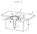
- FIG. 3 is a partially cut away, perspective view illustrating a waterproof structure for a portion where members are tightened, which is a third embodiment according to the present invention, illustrating a tightening section where a first member 1 and a second member 8 are fastened with a flat head screw 4, the tightening section being cut out with a plane passing through a central axis of the flat head screw 4.
- a screw hole 1a with a bottom is provided, and in the second member 8, a screw insertion hole 8a is provided.
- the second member 8 is fastened to the first member 1 by screwing the flat head screw 4 which passes through the screw insertion hole 8a into the screw hole 1a with a bottom.
- a spacer 9 and an O-ring 5 are placed between the flat head screw 4 and the second member 8.
- a recessed circular conical surface 9a is formed to be in surface contact with a circular conical surface of a head of the flat head screw 4, and the outside of the spacer 9 is formed to be an approximately cylindrical surface, and in the cylindrical surface on the side surface, an annular groove 9b is formed.
- the spacer 9 having the O-ring 5 fitted in the annular groove 9b is fitted in a cylindrically shaped dent of the second member 8. Then, the flat head screw 4 is inserted into the recessed circular conical surface 9a of the spacer 9 and an insertion hole communicating with it, and screwed into the screw hole 1a with a bottom of the first member 1.
- the second member 8 is fastened to the first member 1, and at this time, a waterproof property between the spacer 9 and the cylindrical surface 8b of the second member 8 is accomplished by the O-ring 5 pressed against these members. Also, because the circular conical surface of the head of the flat head screw 4 and the recessed circular conical surface 9a are aligned to be completely coaxial with each other when the O-ring 5 is elastically deformed, a waterproof property is accomplished by ensuring a tight surface contact.
- the O-ring 5 is not damaged due to being pressed by the surface, allowing for repeated use. Further, because the head of the flat head screw 4 is put in the screw insertion hole 8a of the second member 8, the head of the flat head screw 4 is not protruded above the second member 8 and a necessary space is not enlarged.
- an annular groove may be provided to fit an O-ring therein, and this O-ring may be pressed by the circular conical surface of the flat head screw. In such a manner, a complete waterproof property between the flat head screw and the spacer can be accomplished.
Landscapes
- Engineering & Computer Science (AREA)
- General Engineering & Computer Science (AREA)
- Mechanical Engineering (AREA)
- Bolts, Nuts, And Washers (AREA)
- Connection Of Plates (AREA)
- Gasket Seals (AREA)
- Casings For Electric Apparatus (AREA)
Abstract
Description
- The present invention relates to a waterproof structure for a portion where members are tightened with a screw.
- FIG. 4 shows an example of a conventional waterproof structure for a portion where members are tightened with a screw. FIG. 4 shows a state of a tightening section where a
first member 10 and a second member 11 are fastened with abolt 12, the tightening section being cut out by a plane passing through a central axis of thebolt 12. - In the
first member 10, a screw hole 10a with a bottom is provided, and in the second member 11, a screw insertion hole 11a is provided. The second member 11 is fastened to thefirst member 10 by screwing thebolt 12 which passes through the screw insertion hole 11a into the screw hole 10a with a bottom. - Then, to form a waterproof structure, a
spacer 13 and apacking 14 are placed between thebolt 12 and the second member 11. In addition, FIG. 4 exaggeratedly shows a state in a larger scale before thepacking 14 is deformed. A ring-like packing 14 having a rectangular cross-section made of rubber is fitted in a dent of thespacer 13 made of metal and placed on the screw insertion hole 11a of the second member 11 mounted on thefirst member 10, and thebolt 12 is inserted into thepacking 14 to be tightly screwed into the screw hole 10a with a bottom. - A lower surface of the
spacer 13 is pressed against an upper surface of the second member 11 by tightening up thebolt 12, and further thepacking 14 is compressed and pressed against an inner surface of thespacer 13, an outer surface of thebolt 12 and the upper surface of the second member 11, providing a waterproof property. - In the conventional waterproof structure for a portion where members are tightened with a screw described above shown in FIG. 4, a bottom surface of the
spacer 13 is arranged to abut on the upper surface of the second member 11 for positioning in the vertical direction, which has presented a problem that the surface of the second member 11 was scraped away, when it was made of resin. Also, thepacking 14 gets entangled with a screw portion of thebolt 12, which leads to a problem that thepacking 14 becomes unusable, when thebolt 12 is repeatedly tightened. - Further, because the
packing 14 gets entangled with the screw portion of thebolt 12 in a process of tightening thebolt 12, thespacer 13 and thepacking 14 are rotated together with thebolt 12, so that there arises a problem that thepacking 14 is likely to be deformed. - Also, because lower surfaces of the
spacer 13 and thepacking 14 are arranged to abut on the upper surface of the second member 11, the upper surface of the second member 11 has to be a horizontal surface. Then, because a head of thebolt 12 is mounted on the upper surface of the second member 11, thespacer 13 and the head of the bolt are protruded from the upper surface of the second member 11, presenting a problem of requiring a larger, necessary space. - In a waterproof structure for apparatuses proposed in
Japanese Patent Application Laid-Open No. 2000-277934 - Then, a through hole 44 is made into the second boss 43 to insert a fixing screw 55 thereinto, and a hole 34 with a bottom is made into the first boss 33 to screw the fixing screw 55 thereto. Also, an annular groove 45 coaxial with the through hole 44 is formed in a surface of the second boss 43 opposite to the first boss 33, and an O-ring 46 is positioned in this annular groove 45.
- On the one hand, in a surface of the first boss 33 opposite to the second boss 43, an annular projection 35 is formed to be opposite to the annular groove 45. Then, when the front case 31 and the rear case 41 are fitted in each other, the annular projection 35 is arranged to press the O-ring 46.
- In the waterproof structure for apparatuses proposed in
Japanese Patent Application Laid-Open No. 2000-277934 - The present invention was made in view of the points described above, and an object thereof is to provide a waterproof structure for a portion where members are tightened with a screw, not damaging the members and allowing for repeated use, with a necessary space not being enlarged.
- A waterproof structure for a portion where members are tightened with a screw according to the present invention is a waterproof structure for a tightening section where a first member having a screw hole with a bottom and a second member having a screw insertion hole with a screw that is inserted into the screw insertion hole and screwed to the screw hole, the waterproof structure being configured in such a way that the screw is a flat head screw, an annular groove coaxial with a recessed circular conical surface is provided in an outer surface of a spacer fitted in the screw insertion hole, having an insertion hole, in which the recessed circular conical surface is formed to be in surface contact with a circular conical surface of a head of the flat head screw, an O-ring is fitted in the annular groove, the spacer is placed between the first member and the second member, and the O-ring is pressed against an inner surface of the annular groove and a surface of the screw insertion hole of the second member by tightening up the flat head screw.
- Also, in the waterproof structure for a portion where members are tightened with a screw described above, the surface of the second member against which the O-ring is pressed is a circular conical surface coaxial with the flat head screw.
- Further, in the waterproof structure for a portion where members are tightened with a screw described above, the surface of the second member against which the O-ring is pressed is a plane surface orthogonal to a central axis of the flat head screw.
- Moreover, in the waterproof structure for a portion where members are tightened with a screw described above, the surface of the second member against which the O-ring is pressed is a cylindrical surface coaxial with the flat head screw.
- Owing to the waterproof structures for a portion where members are tightened with a screw according to the present invention, the O-ring is pressed by the surface not to be damaged, enabling repeated use. Further, the head of the flat head screw is put in the screw insertion hole of the second member, therefore the head of the screw is not protruded above the second member, eliminating enlargement of a necessary space.
-
- FIG. 1 is a partially cut away, perspective view illustrating a waterproof structure for a portion where members are tightened, of a first embodiment according to the present invention;
- FIG. 2 is a partially cut away, perspective view illustrating a waterproof structure for a portion where members are tightened, of a second embodiment according to the present invention;
- FIG. 3 is a partially cut away, perspective view illustrating a waterproof structure for a portion where members are tightened, of a third embodiment according to the present invention; and
- FIG. 4 is a partially cut away, perspective view illustrating a waterproof structure for a portion where members are tightened, of a conventional technique.
- Now, a best mode for carrying out the present invention will be hereinafter described with reference to embodiments.
- FIG. 1 is a partially cut away, perspective view illustrating a waterproof structure for a portion where members are tightened, of a first embodiment according to the present invention, illustrating a tightening section where a first member 1 and a second member 2 are fastened with a
flat head screw 4, the tightening section being cut out with a plane passing through a central axis of theflat head screw 4. - In the first member 1 shown in FIG. 1, a screw hole 1a with a bottom is provided, and in the second member 2, a
screw insertion hole 2a is provided. The second member 2 is fastened to the first member 1 by screwing theflat head screw 4 which passes through thescrew insertion hole 2a into the screw hole 1a with a bottom. - Then, to form a waterproof structure, a
spacer 3 and an O-ring 5 are placed between theflat head screw 4 and the second member 2. In the inside of thespacer 3, a recessed circularconical surface 3a is formed to be in surface contact with a circular conical surface of a head of theflat head screw 4, and in the outside of thespacer 3, anannular groove 3b is formed. - The
spacer 3 having the O-ring 5 fitted in theannular groove 3b is fitted in a circularconical surface 2b of the second member 2. Then, theflat head screw 4 is inserted into the recessed circularconical surface 3a of thespacer 3 and an insertion hole communicating with it, and screwed into the screw hole 1a with a bottom of the first member 1. - In such a manner, the second member 2 is fastened to the first member 1, and at this time, a waterproof property between the
spacer 3 and the second member 2 is accomplished by the O-ring 5 pressed against these members. Also, because the circular conical surface of the head of theflat head screw 4 and the recessed circularconical surface 3a are aligned to be completely coaxial with each other when the O-ring 5 is elastically deformed, a waterproof property is accomplished by ensuring a tight surface contact. - The O-
ring 5 is not damaged due to being pressed by the surface, allowing for repeated use. Further, because the head of theflat head screw 4 is put in thescrew insertion hole 2a of the second member 2, the head of theflat head screw 4 is not protruded above the second member 2 and a necessary space is not enlarged. - FIG. 2 is a partially cut away, perspective view illustrating a waterproof structure for a portion where members are tightened, of a second embodiment according to the present invention, illustrating a tightening section where a first member 1 and a
second member 6 are fastened with aflat head screw 4, the tightening section being cut out with a plane passing through a central axis of theflat head screw 4. - In the first member 1 shown in FIG. 2, a screw hole 1a with a bottom is provided, and in the
second member 6, ascrew insertion hole 6a is provided. Thesecond member 6 is fastened to the first member 1 by screwing theflat head screw 4 which passes through thescrew insertion hole 6a into the screw hole 1a with a bottom. - Then, to form a waterproof structure, a
spacer 7 and an O-ring 5 are placed between theflat head screw 4 and thesecond member 6. In the inside of thespacer 7, a recessed circularconical surface 7a is formed to be in surface contact with a circular conical surface of a head of theflat head screw 4, and the outside of thespacer 7 is formed to be an approximately cylindrical surface, and in a lower surface thereof, anannular groove 7b is formed. - The
spacer 7 having the O-ring 5 fitted in theannular groove 7b is fitted in a cylindrically shaped dent of thesecond member 6. Then, theflat head screw 4 is inserted into the recessed circularconical surface 7a of thespacer 7 and an insertion hole communicating with it, and screwed into the screw hole 1a with a bottom of the first member 1. - In such a manner, the
second member 6 is fastened to the first member 1, and at this time, a waterproof property between thespacer 7 and aplane surface 6b of thesecond member 6 is accomplished by the O-ring 5 pressed against these members. Also, because the circular conical surface of the head of theflat head screw 4 and the recessed circularconical surface 7a are aligned to be completely coaxial with each other when the O-ring 5 is elastically deformed, a waterproof property is accomplished by ensuring a tight surface contact. - The O-
ring 5 is not damaged due to being pressed by the surface, allowing for repeated use. Further, because the head of theflat head screw 4 is put in thescrew insertion hole 6a of thesecond member 6, the head of theflat head screw 4 is not protruded above thesecond member 6 and a necessary space is not enlarged. - FIG. 3 is a partially cut away, perspective view illustrating a waterproof structure for a portion where members are tightened, which is a third embodiment according to the present invention, illustrating a tightening section where a first member 1 and a
second member 8 are fastened with aflat head screw 4, the tightening section being cut out with a plane passing through a central axis of theflat head screw 4. - In the first member 1 shown in FIG. 3, a screw hole 1a with a bottom is provided, and in the
second member 8, ascrew insertion hole 8a is provided. Thesecond member 8 is fastened to the first member 1 by screwing theflat head screw 4 which passes through thescrew insertion hole 8a into the screw hole 1a with a bottom. - Then, to form a waterproof structure, a
spacer 9 and an O-ring 5 are placed between theflat head screw 4 and thesecond member 8. In the inside of thespacer 9, a recessed circularconical surface 9a is formed to be in surface contact with a circular conical surface of a head of theflat head screw 4, and the outside of thespacer 9 is formed to be an approximately cylindrical surface, and in the cylindrical surface on the side surface, anannular groove 9b is formed. - The
spacer 9 having the O-ring 5 fitted in theannular groove 9b is fitted in a cylindrically shaped dent of thesecond member 8. Then, theflat head screw 4 is inserted into the recessed circularconical surface 9a of thespacer 9 and an insertion hole communicating with it, and screwed into the screw hole 1a with a bottom of the first member 1. - In such a manner, the
second member 8 is fastened to the first member 1, and at this time, a waterproof property between thespacer 9 and thecylindrical surface 8b of thesecond member 8 is accomplished by the O-ring 5 pressed against these members. Also, because the circular conical surface of the head of theflat head screw 4 and the recessed circularconical surface 9a are aligned to be completely coaxial with each other when the O-ring 5 is elastically deformed, a waterproof property is accomplished by ensuring a tight surface contact. - Also, the O-
ring 5 is not damaged due to being pressed by the surface, allowing for repeated use. Further, because the head of theflat head screw 4 is put in thescrew insertion hole 8a of thesecond member 8, the head of theflat head screw 4 is not protruded above thesecond member 8 and a necessary space is not enlarged. - The embodiments are configured as described above, but the present invention is not limited to these, for example, in the recessed circular
conical surfaces spacers - In a portion where members are tightened with a screw, there can be provided a very effective waterproof structure both technically and for use.
Claims (4)
- A waterproof structure for a portion where members are tightened with a screw, for fastening by a first member having a screw hole with a bottom and a second member having a screw insertion hole with a screw that is inserted into the screw insertion hole and screwed to the screw hole, wherein the waterproof structure being configured in such a way that
the screw is a flat head screw,
an annular groove coaxial with a recessed circular conical surface is provided in an outer surface of a spacer fitted in the screw insertion hole, having an insertion hole in which the recessed circular conical surface is formed to be in surface contact with a circular conical surface of a head of the flat head screw,
an O-ring is fitted in the annular groove,
the spacer is placed between the first member and the second member, and
the O-ring is pressed against an inner surface of the annular groove and a surface of the screw insertion hole of the second member by tightening up the flat head screw. - The waterproof structure according to claim 1, wherein
the surface of the second member against which the O-ring is pressed is a circular conical surface coaxial with the flat head screw. - The waterproof structure according to claim 1, wherein
the surface of the second member against which the O-ring is pressed is a plane surface orthogonal to a central axis of the flat head screw. - The waterproof structure according to claim 1, wherein
the surface of the second member against which the 0-ring is pressed is a cylindrical surface coaxial with the flat head screw.
Applications Claiming Priority (2)
| Application Number | Priority Date | Filing Date | Title |
|---|---|---|---|
| JP2005143507A JP4729977B2 (en) | 2005-05-17 | 2005-05-17 | Waterproof structure for fastening parts with screws |
| PCT/JP2006/310092 WO2006123809A1 (en) | 2005-05-17 | 2006-05-16 | Waterproof structure for portion where members are tightened with screw |
Publications (2)
| Publication Number | Publication Date |
|---|---|
| EP1882872A1 true EP1882872A1 (en) | 2008-01-30 |
| EP1882872A4 EP1882872A4 (en) | 2012-03-28 |
Family
ID=37431372
Family Applications (1)
| Application Number | Title | Priority Date | Filing Date |
|---|---|---|---|
| EP06732666A Withdrawn EP1882872A4 (en) | 2005-05-17 | 2006-05-16 | Waterproof structure for portion where members are tightened with screw |
Country Status (6)
| Country | Link |
|---|---|
| US (1) | US7740433B2 (en) |
| EP (1) | EP1882872A4 (en) |
| JP (1) | JP4729977B2 (en) |
| CN (1) | CN101180481A (en) |
| DE (1) | DE06732666T1 (en) |
| WO (1) | WO2006123809A1 (en) |
Families Citing this family (21)
| Publication number | Priority date | Publication date | Assignee | Title |
|---|---|---|---|---|
| US8282108B2 (en) * | 2010-03-19 | 2012-10-09 | Unisaf Enterprise Company Limited | Water leakage-proof apparatus |
| JP5364045B2 (en) * | 2010-06-11 | 2013-12-11 | 川崎重工業株式会社 | Hydraulic equipment plugs |
| JP5498903B2 (en) * | 2010-09-27 | 2014-05-21 | メイラ株式会社 | Male fasteners |
| TWI461611B (en) * | 2011-08-03 | 2014-11-21 | Wistron Corp | Screw with a water-proof structure |
| EP2653376B1 (en) * | 2012-04-18 | 2016-03-23 | Airbus Operations, S.L. | Bolted joint of the cover of an access opening in an aircraft lifting surface |
| EP2913573A1 (en) * | 2014-02-26 | 2015-09-02 | VAT Holding AG | Vacuum valve |
| US9939004B2 (en) * | 2014-09-17 | 2018-04-10 | Arconic Inc | Coated fasteners with conforming seals |
| US20170189970A1 (en) * | 2016-01-04 | 2017-07-06 | Ching-Ting Chen | Bidirectional adjusting cutter holder |
| CN105526226A (en) * | 2016-01-15 | 2016-04-27 | 安徽江淮汽车股份有限公司 | Connection structure |
| US10527084B2 (en) * | 2016-05-19 | 2020-01-07 | Christopher Prevost | Elastomeric collar for fasteners |
| US11118616B2 (en) | 2016-05-19 | 2021-09-14 | Christopher Prevost | Vibration isolator for turnlock fasteners |
| JP6852176B2 (en) | 2016-12-13 | 2021-03-31 | アーコニック インコーポレイテッドArconic Inc. | Reduced electromagnetic signature of conformal conical seal fastener system |
| CN106678136A (en) * | 2017-02-21 | 2017-05-17 | 东莞市鹏翼自动化科技有限公司 | A structure for installing and fixing wooden panels on a steel structure |
| CN106763031A (en) * | 2017-02-21 | 2017-05-31 | 东莞市鹏翼自动化科技有限公司 | A construction for installing and fixing wooden panels on a concrete structure wall |
| US10190529B1 (en) * | 2017-10-06 | 2019-01-29 | Brunswick Corporation | Marine engines having cylinder block cooling jacket with spacer |
| EP3807543B1 (en) * | 2018-06-12 | 2026-05-13 | Sherex Fastening Solutions LLC | Rivet-like fastener and compression seal assembly |
| TW202033863A (en) | 2018-10-31 | 2020-09-16 | 美商艾斯克集團有限責任公司 | Wear assembly |
| TWI692687B (en) * | 2019-03-08 | 2020-05-01 | 和碩聯合科技股份有限公司 | Locking mechanism |
| CN110159632A (en) * | 2019-06-21 | 2019-08-23 | 重庆青山工业有限责任公司 | Fastening bolt and clamp device |
| US20240003376A1 (en) * | 2022-06-29 | 2024-01-04 | Hamilton Sundstrand Corporation | Manifold with repairable thread insert assemblies within manifold boreholes |
| JP2024038717A (en) * | 2022-09-08 | 2024-03-21 | 株式会社マリンテック | Lighting equipment for ships, etc. and method for preventing galvanic corrosion thereof |
Family Cites Families (19)
| Publication number | Priority date | Publication date | Assignee | Title |
|---|---|---|---|---|
| US2735572A (en) * | 1956-02-21 | Filler cap assembly | ||
| US2884099A (en) * | 1954-03-26 | 1959-04-28 | Rohr Aircraft Corp | Sealed riveted joint |
| US3884006A (en) * | 1973-01-05 | 1975-05-20 | Robert W Dietlein | Sandwich panel insert |
| JPS58191414A (en) | 1982-05-04 | 1983-11-08 | 三洋電機株式会社 | Solid electrolytic condenser |
| JPS58191414U (en) * | 1982-06-16 | 1983-12-20 | 昭和電工建材株式会社 | watertight screws |
| JPS6184796A (en) | 1984-10-02 | 1986-04-30 | 株式会社テクノロジー・リソーシズ・インコーポレーテツド | Oxygen enriched air vending machine |
| JPH0330474Y2 (en) * | 1984-11-02 | 1991-06-27 | ||
| JPH02101120A (en) * | 1988-10-06 | 1990-04-12 | Nippon Steel Corp | Production of grain oriented electrical steel sheet having excellent magnetic characteristic |
| JPH02101120U (en) * | 1989-01-27 | 1990-08-13 | ||
| JP2793310B2 (en) * | 1989-12-29 | 1998-09-03 | 株式会社トープラ | Screw fastening structure |
| JP2759239B2 (en) * | 1992-06-30 | 1998-05-28 | ミネベア株式会社 | Inlet seal body |
| US5340255A (en) * | 1993-04-26 | 1994-08-23 | Avibank Mfg., Inc. | Plug locking assembly |
| WO1998039141A1 (en) * | 1997-03-07 | 1998-09-11 | Yutaka Maeda | Collet and fastener using same |
| US5988965A (en) * | 1997-06-25 | 1999-11-23 | Mcdonnell Douglas Corporation | Locking fastener |
| JPH1137132A (en) * | 1997-07-18 | 1999-02-09 | Hitachi Ltd | bolt |
| JPH1137133A (en) | 1997-07-23 | 1999-02-09 | Toopura:Kk | Synthetic resin-made washer |
| JPH11229790A (en) | 1998-02-17 | 1999-08-24 | Okumura Corp | Closed structure of segment and working hole in segment |
| JP2005036962A (en) * | 2003-06-30 | 2005-02-10 | Fujiwa Shokai:Kk | Fastener with washer |
| JP4295033B2 (en) | 2003-07-31 | 2009-07-15 | 日本パワーファスニング株式会社 | Synthetic resin washer |
-
2005
- 2005-05-17 JP JP2005143507A patent/JP4729977B2/en not_active Expired - Lifetime
-
2006
- 2006-05-16 EP EP06732666A patent/EP1882872A4/en not_active Withdrawn
- 2006-05-16 DE DE06732666T patent/DE06732666T1/en active Pending
- 2006-05-16 WO PCT/JP2006/310092 patent/WO2006123809A1/en not_active Ceased
- 2006-05-16 CN CNA2006800173061A patent/CN101180481A/en active Pending
- 2006-05-16 US US11/920,502 patent/US7740433B2/en not_active Expired - Fee Related
Also Published As
| Publication number | Publication date |
|---|---|
| DE06732666T1 (en) | 2008-07-03 |
| WO2006123809A1 (en) | 2006-11-23 |
| EP1882872A4 (en) | 2012-03-28 |
| JP4729977B2 (en) | 2011-07-20 |
| US20090104000A1 (en) | 2009-04-23 |
| JP2006322469A (en) | 2006-11-30 |
| CN101180481A (en) | 2008-05-14 |
| US7740433B2 (en) | 2010-06-22 |
Similar Documents
| Publication | Publication Date | Title |
|---|---|---|
| US7740433B2 (en) | Waterproof structure for portion where members are tightened with screw | |
| JP4276196B2 (en) | Vehicle roof antenna mounting device | |
| US6714171B2 (en) | Antenna mounting apparatuses and methods | |
| US8657257B2 (en) | Gate valve | |
| JP2012189160A (en) | Bolt loosening prevention device, its attachment method and attachment jig | |
| EP2988399B1 (en) | Fastening system for a terminal box and electrical machine | |
| WO2003095270A1 (en) | Load carrier support | |
| JP2005123120A (en) | Connector for board | |
| KR102091715B1 (en) | Connecting Apparatus for Plate Type Member | |
| US7387519B2 (en) | Device for protecting electric component | |
| JP2008259969A (en) | Masking tool | |
| JP6573422B2 (en) | Wiring equipment attachment device and equipment support | |
| KR101909493B1 (en) | Apparatus for Fasteninga Shark Fin Type Antenna of Roof Panel | |
| JP2005229762A (en) | Electrical connection box for automobile | |
| KR100986424B1 (en) | Battery terminal connection assembly | |
| US20250030208A1 (en) | Rear-mountable connector housing | |
| CN115004483A (en) | Attached shell | |
| CN206351880U (en) | The component of cap assemblies and container | |
| CA3209606A1 (en) | Strip mounting system for mounting strip | |
| EP1742293B1 (en) | Antenna mounting apparatuses | |
| US7626833B1 (en) | Switch assembling structure | |
| JP3274059B2 (en) | Component mounting structure and electrical component box having the same | |
| JP4932422B2 (en) | Electronic device unit mounting structure | |
| KR200452701Y1 (en) | Cable connection module | |
| KR200455840Y1 (en) | Assembly structure of stud plate for large display device |
Legal Events
| Date | Code | Title | Description |
|---|---|---|---|
| PUAI | Public reference made under article 153(3) epc to a published international application that has entered the european phase |
Free format text: ORIGINAL CODE: 0009012 |
|
| 17P | Request for examination filed |
Effective date: 20071115 |
|
| AK | Designated contracting states |
Kind code of ref document: A1 Designated state(s): DE FR GB |
|
| EL | Fr: translation of claims filed | ||
| DAX | Request for extension of the european patent (deleted) | ||
| RBV | Designated contracting states (corrected) |
Designated state(s): DE FR GB |
|
| DET | De: translation of patent claims | ||
| A4 | Supplementary search report drawn up and despatched |
Effective date: 20120224 |
|
| RIC1 | Information provided on ipc code assigned before grant |
Ipc: F16J 15/06 20060101AFI20120220BHEP Ipc: F16B 5/02 20060101ALI20120220BHEP Ipc: F16B 43/00 20060101ALI20120220BHEP |
|
| RAP1 | Party data changed (applicant data changed or rights of an application transferred) |
Owner name: JVC KENWOOD CORPORATION |
|
| 17Q | First examination report despatched |
Effective date: 20121009 |
|
| STAA | Information on the status of an ep patent application or granted ep patent |
Free format text: STATUS: THE APPLICATION HAS BEEN WITHDRAWN |
|
| 18W | Application withdrawn |
Effective date: 20130124 |