EP1882844A1 - Valve assembly for an Injection valve and injection valve - Google Patents
Valve assembly for an Injection valve and injection valve Download PDFInfo
- Publication number
- EP1882844A1 EP1882844A1 EP06015488A EP06015488A EP1882844A1 EP 1882844 A1 EP1882844 A1 EP 1882844A1 EP 06015488 A EP06015488 A EP 06015488A EP 06015488 A EP06015488 A EP 06015488A EP 1882844 A1 EP1882844 A1 EP 1882844A1
- Authority
- EP
- European Patent Office
- Prior art keywords
- fluid
- channel portion
- recess
- valve
- fluid flow
- Prior art date
- Legal status (The legal status is an assumption and is not a legal conclusion. Google has not performed a legal analysis and makes no representation as to the accuracy of the status listed.)
- Withdrawn
Links
Images



Classifications
-
- F—MECHANICAL ENGINEERING; LIGHTING; HEATING; WEAPONS; BLASTING
- F02—COMBUSTION ENGINES; HOT-GAS OR COMBUSTION-PRODUCT ENGINE PLANTS
- F02M—SUPPLYING COMBUSTION ENGINES IN GENERAL WITH COMBUSTIBLE MIXTURES OR CONSTITUENTS THEREOF
- F02M61/00—Fuel-injectors not provided for in groups F02M39/00 - F02M57/00 or F02M67/00
- F02M61/16—Details not provided for in, or of interest apart from, the apparatus of groups F02M61/02 - F02M61/14
- F02M61/162—Means to impart a whirling motion to fuel upstream or near discharging orifices
-
- F—MECHANICAL ENGINEERING; LIGHTING; HEATING; WEAPONS; BLASTING
- F02—COMBUSTION ENGINES; HOT-GAS OR COMBUSTION-PRODUCT ENGINE PLANTS
- F02M—SUPPLYING COMBUSTION ENGINES IN GENERAL WITH COMBUSTIBLE MIXTURES OR CONSTITUENTS THEREOF
- F02M61/00—Fuel-injectors not provided for in groups F02M39/00 - F02M57/00 or F02M67/00
- F02M61/16—Details not provided for in, or of interest apart from, the apparatus of groups F02M61/02 - F02M61/14
- F02M61/18—Injection nozzles, e.g. having valve seats; Details of valve member seated ends, not otherwise provided for
Definitions
- the invention relates to a valve assembly for an injection valve and an injection valve.
- Injection valves are in wide spread use, in particular for internal combustion engines where they may be arranged in order to dose the fluid into an intake manifold of the internal combustion engine or directly into the combustion chamber of a cylinder of the internal combustion engine.
- injection valves are manufactured in various forms in order to satisfy the various needs for the various combustion engines. Therefore, for example, their length, their diameter and also various elements of the injection valve being responsible for the way the fluid is dosed may vary in a wide range.
- injection valves may accommodate an actuator for actuating a needle of the injection valve, which may, for example, be an electromagnetic actuator or piezo electric actuator.
- the respective injection valve may be suited to dose fluids under very high pressures.
- the pressures may be in case of a gasoline engine, for example, in the range of up to 200 bar and in the case of diesel engines in the range of up to 2000 bar.
- the object of the invention is to create a valve assembly which facilitates a reliable and precise function.
- the characteristic of the fluid flow releasing through the fluid outlet portion can be strongly influenced by the shape of the valve assembly in the area of the fluid outlet portion.
- the advantage of the invention is that the fluid flow receives a high fluid flow velocity available at the downstream end of the channel portion where the fluid leaves the fluid flow directing element. By this, a high fuel pressure is available at the downstream end of the channel portion and, consequently, a large cone angle of the spray of the fluid is possible.
- the cross-section of the channel portion is decreasing continuously from the upstream end of the channel portion to the downstream end of the channel portion. This has the advantage that the highest velocities of the fluid are available at the downstream end of the channel portion. This can increase the tangential speed of the fluid flow when the fluid flow leaves the fluid flow directing element.
- the recess fluid inlet portion and the channel portion are formed and arranged in a way that the transition between the recess fluid inlet portion and the channel portion is stepless.
- the channel portion has a conical shape.
- Conical shapes can be easily manufactured. A stepless transition between the channel portion and the recess fluid inlet portion of the fluid flow directing element is possible. Furthermore, the conical shape enables small pressure losses at the upstream end of the channel portion.
- a longitudinal section of the channel portion is of a convex shape. This has the advantage that a stepless transition between the channel portion and the recess fluid inlet portion is possible. Furthermore, a high fluid velocity is available at the downstream end of the channel portion.
- the longitudinal section of the channel portion is of a concave shape. This allows a stepless transition between the channel portion and the recess fluid inlet portion.
- An injection valve 62 (figure 1), that is in particular suitable for dosing fuel to an internal combustion engine, comprises an inlet tube 2, a housing 6 and a valve assembly 60.
- the valve assembly 60 comprises a valve body 4 with a central longitudinal axis L and a cavity 8, which takes in a valve needle 10 and preferably a part of an armature 12.
- the valve needle 10 has a surface 11 and a seat part 64.
- a recess 16 is provided which further extends to a recess 18 of the armature 12.
- a spring 14 is arranged in the recess 16 of the inlet tube 2 and/or the recess 18 of the armature 12. Preferably, it rests on a spring seat being formed by an anti-bounce disc 20. By this the spring 14 is mechanically coupled to the needle 10.
- An adjusting tube 22 is provided in the recess 16 of the inlet tube 2.
- the adjusting tube 22 forms a further seat for the spring 14 and may be axially moved during the manufacturing process of the fluid injection valve in order to preload the spring 14 in a desired way.
- the injection nozzle 24 may be, for example, an injection hole. However, it may also be of some other type suitable for dosing fluid.
- the seat plate 26 may be made in one part with the valve body 4 or a separate part from the valve body 4.
- a lower guide 28 for guiding the needle 10 is provided.
- the lower guide 28 further comprises an orifice 70 for guiding the fluid flow.
- a fluid flow directing element 30 is provided which is arranged in the cavity 8 between the lower guide 28 and the seat plate 26.
- the injection valve is provided with an actuator unit, that comprises preferably an electromagnetic actuator, comprising a coil 36, which is preferably overmolded.
- an actuator unit that comprises preferably an electromagnetic actuator, comprising a coil 36, which is preferably overmolded.
- a valve body shell 38, the armature 12 and the inlet tube 2 are forming an electromagnetic circuit.
- the actuator unit may, however, also comprise another type of actuator, which is known to a person skilled in the art for that purpose.
- Such an actuator may be, for example, a piezoelectric actuator.
- a fluid inlet portion 42 is provided in the valve body 4 which communicates with a fluid outlet portion 44 which is a part of the cavity 8 near the seat plate 26.
- the fluid flow directing element 30 has the shape of a cylindrical disk.
- the fluid flow directing element 30 comprises recesses 46 to direct the fluid flow to the fluid outlet portion 44.
- Each of the recesses 46 has a recess fluid inlet portion 48 and a channel portion 50, both with an inner surface 56.
- the recess fluid inlet portion 48 is hydraulically coupled to the orifice 70 in the lower guide 28.
- the channel portion 50 has an upstream end 52 and a downstream end 54. At the upstream end 52 the channel portion 50 is hydraulically coupled with the recess fluid inlet portion 48.
- the downstream end 54 of the channel portion 50 enables a hydraulic coupling of the channel portion 50 with the fluid outlet portion 44.
- the cross-section of the upstream end 52 of the channel portion 50 is larger than the cross-section of the downstream end 54 of the channel portion 50. Therefore, the velocity of the fluid flow at the downstream end 54 of the channel portion 50 is higher than the velocity of the fluid flow at the upstream end 52 of the channel portion 50.
- the cross-section of the channel portion 50 is decreasing continuously from the upstream end 52 of the channel portion 50 to the downstream end 54 of the channel portion 50. Therefore, the highest velocities of the fluid in the channel portion 50 are available at the downstream end 54 of the channel portion 50.
- the transition between the recess fluid inlet portion 48 and the channel portion 50 is continuous which means that no step or edge is on the inner surface 56 of the recess 46 in the transition between the recess fluid inlet portion 48 and the channel portion 50. Consequently, the pressure losses at the upstream end 52 of the channel portion 50 can be small and the fluid flow speed at the downstream end 54 of the channel portion 50 can be large. This means that the tangential speed of the fluid flow when the fluid enters the fluid outlet portion 44 can be large which can result in a large radial component of the fluid flow and the distribution of the fluid in radial direction can be very good. This can result in an increased spray angle of the fluid flow through the injection nozzle 24 and a good distribution of droplets of the spray.
- the channel portion has a conical shape.
- Conical shapes are simple to manufacture and a good adjustment of the channel portion 50 to the recess fluid inlet portion 48 is possible. This allows a stepless transition between the channel portion 50 and the recess fluid inlet portion 48. By this, small pressure losses at the upstream end 52 of the channel portion 50 and high fluid flow velocities at the downstream end 54 of the channel portion 50 are possible.
- the channel portion 50 has a convex shape (figure 5) or a concave shape having the shape of a drop (figure 6). These two embodiments allow good adaptation of the channel portion 50 to the recess fluid inlet portion 48 with a stepless transition between the channel portion 50 and the recess fluid inlet portion 48.
- the fluid is led from the fluid inlet portion 42 to the fluid outlet portion 44.
- the axial position of the valve needle 10, which determines whether the fluid outlet portion 44 is opened or closed for a fluid flow, depends on the force balance between the spring 14 and the forces applied to the valve needle 10 by the actuator unit with the coil 36.
- the fluid flow through the fluid outlet portion 44 can be described with a flow path 68 with flow path sections 68a, 68b.
- the fluid flow on the flow path 68 is passing the fluid flow directing element 30 thereby being accelerated in the channel portion 50.
- the fluid flow obtains a radial velocity component which results in a distribution of droplets in a spray in the flow path section 68b of the second flow path 68.
- the radial component of the fluid flow velocity on the flow path section 68b is high and a good distribution of fluid in radial direction is available. Therefore the fluid flow through the injection nozzle 24 generating a spray can result in a large spray angle and a good distribution of the droplets of the spray.
Landscapes
- Engineering & Computer Science (AREA)
- Chemical & Material Sciences (AREA)
- Combustion & Propulsion (AREA)
- Mechanical Engineering (AREA)
- General Engineering & Computer Science (AREA)
- Fuel-Injection Apparatus (AREA)
Abstract
Description
- The invention relates to a valve assembly for an injection valve and an injection valve.
- Injection valves are in wide spread use, in particular for internal combustion engines where they may be arranged in order to dose the fluid into an intake manifold of the internal combustion engine or directly into the combustion chamber of a cylinder of the internal combustion engine.
- Injection valves are manufactured in various forms in order to satisfy the various needs for the various combustion engines. Therefore, for example, their length, their diameter and also various elements of the injection valve being responsible for the way the fluid is dosed may vary in a wide range. In addition to that, injection valves may accommodate an actuator for actuating a needle of the injection valve, which may, for example, be an electromagnetic actuator or piezo electric actuator.
- In order to enhance the combustion process in view of the creation of unwanted emissions, the respective injection valve may be suited to dose fluids under very high pressures. The pressures may be in case of a gasoline engine, for example, in the range of up to 200 bar and in the case of diesel engines in the range of up to 2000 bar.
- The object of the invention is to create a valve assembly which facilitates a reliable and precise function.
- These objects are achieved by the features of the independent claim. Advantageous embodiments of the invention are given in the sub-claims.
- The invention is distinguished by a valve assembly for an injection valve, comprising a valve body including a central longitudinal axis, the valve body comprising a cavity with a fluid inlet portion and a fluid outlet portion, and a valve needle axially moveable in the cavity, the valve needle preventing a fluid flow through the fluid outlet portion in a closing position and releasing the fluid flow through the fluid outlet portion in further positions. Furthermore, the valve assembly comprises a fluid flow directing element arranged in the cavity and comprises a recess to direct the fluid flow to the fluid outlet portion. The recess has a recess fluid inlet portion and a channel portion arranged between the recess fluid inlet portion and the fluid outlet portion, and the channel portion has an upstream end and a downstream end. The cross section of the downstream end of the channel portion is smaller than the cross section of the upstream end of the channel portion.
- The characteristic of the fluid flow releasing through the fluid outlet portion can be strongly influenced by the shape of the valve assembly in the area of the fluid outlet portion. The advantage of the invention is that the fluid flow receives a high fluid flow velocity available at the downstream end of the channel portion where the fluid leaves the fluid flow directing element. By this, a high fuel pressure is available at the downstream end of the channel portion and, consequently, a large cone angle of the spray of the fluid is possible.
- Preferably, the cross-section of the channel portion is decreasing continuously from the upstream end of the channel portion to the downstream end of the channel portion. This has the advantage that the highest velocities of the fluid are available at the downstream end of the channel portion. This can increase the tangential speed of the fluid flow when the fluid flow leaves the fluid flow directing element.
- In an advantageous embodiment of the invention, the recess fluid inlet portion and the channel portion are formed and arranged in a way that the transition between the recess fluid inlet portion and the channel portion is stepless. By this, small pressure losses at the upstream end of the channel portion are possible. Consequently, a big fluid pressure is available at the downstream end of the channel portion and the radial component of the fluid flow releasing through the fluid outlet portion can be large. This makes is possible that the fluid flow releasing through the fluid outlet portion, which can be a spray, can have a big spray angle and a favorable distribution of fluid droplets.
- Preferably, the channel portion has a conical shape. Conical shapes can be easily manufactured. A stepless transition between the channel portion and the recess fluid inlet portion of the fluid flow directing element is possible. Furthermore, the conical shape enables small pressure losses at the upstream end of the channel portion.
- In an advantageous embodiment of the invention, a longitudinal section of the channel portion is of a convex shape. This has the advantage that a stepless transition between the channel portion and the recess fluid inlet portion is possible. Furthermore, a high fluid velocity is available at the downstream end of the channel portion.
- In a further advantageous embodiment of the invention, the longitudinal section of the channel portion is of a concave shape. This allows a stepless transition between the channel portion and the recess fluid inlet portion.
- Exemplary embodiments of the invention are explained in the following with the aid of schematic drawings. These are as follows:
- Figure 1, an injection valve with a valve assembly in a longitudinal section view,
- Figure 2, section II of the valve assembly of the injection valve according to figure 1 in a longitudinal section view,
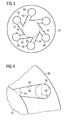
- Figure 3, a fluid flow directing element of the valve assembly of the injection valve in a cross section view,
- Figure 4, an enlarged view of a section of the fluid flow directing element of the valve assembly of the injection valve in a cross section view in one embodiment,
- Figure 5, an enlarged view of a section of the fluid flow directing element of the valve assembly of the injection valve in a cross section view in a second embodiment, and
- Figure 6, an enlarged view of a section of the fluid flow directing element of the valve assembly of the injection valve in a cross section view in a further embodiment.
- Elements of the same design and function that appear in different illustrations are identified by the same reference character.
- An injection valve 62 (figure 1), that is in particular suitable for dosing fuel to an internal combustion engine, comprises an
inlet tube 2, ahousing 6 and avalve assembly 60. - The
valve assembly 60 comprises avalve body 4 with a central longitudinal axis L and acavity 8, which takes in avalve needle 10 and preferably a part of anarmature 12. Thevalve needle 10 has asurface 11 and aseat part 64. In the inlet tube 2 arecess 16 is provided which further extends to arecess 18 of thearmature 12. Aspring 14 is arranged in therecess 16 of theinlet tube 2 and/or therecess 18 of thearmature 12. Preferably, it rests on a spring seat being formed by ananti-bounce disc 20. By this thespring 14 is mechanically coupled to theneedle 10. An adjustingtube 22 is provided in therecess 16 of theinlet tube 2. The adjustingtube 22 forms a further seat for thespring 14 and may be axially moved during the manufacturing process of the fluid injection valve in order to preload thespring 14 in a desired way. - In a closing position of the
needle 10 it sealingly rests on aseat plate 26 by this preventing a fluid flow through at least oneinjection nozzle 24. Theinjection nozzle 24 may be, for example, an injection hole. However, it may also be of some other type suitable for dosing fluid. Theseat plate 26 may be made in one part with thevalve body 4 or a separate part from thevalve body 4. In addition to that alower guide 28 for guiding theneedle 10 is provided. Thelower guide 28 further comprises anorifice 70 for guiding the fluid flow. - Additionally, a fluid
flow directing element 30 is provided which is arranged in thecavity 8 between thelower guide 28 and theseat plate 26. - The injection valve is provided with an actuator unit, that comprises preferably an electromagnetic actuator, comprising a
coil 36, which is preferably overmolded. Avalve body shell 38, thearmature 12 and theinlet tube 2 are forming an electromagnetic circuit. The actuator unit may, however, also comprise another type of actuator, which is known to a person skilled in the art for that purpose. Such an actuator may be, for example, a piezoelectric actuator. - A
fluid inlet portion 42 is provided in thevalve body 4 which communicates with afluid outlet portion 44 which is a part of thecavity 8 near theseat plate 26. - The fluid
flow directing element 30 has the shape of a cylindrical disk. The fluidflow directing element 30 comprisesrecesses 46 to direct the fluid flow to thefluid outlet portion 44. Each of therecesses 46 has a recessfluid inlet portion 48 and achannel portion 50, both with aninner surface 56. The recessfluid inlet portion 48 is hydraulically coupled to theorifice 70 in thelower guide 28. Thechannel portion 50 has anupstream end 52 and adownstream end 54. At theupstream end 52 thechannel portion 50 is hydraulically coupled with the recessfluid inlet portion 48. Thedownstream end 54 of thechannel portion 50 enables a hydraulic coupling of thechannel portion 50 with thefluid outlet portion 44. - The cross-section of the
upstream end 52 of thechannel portion 50 is larger than the cross-section of thedownstream end 54 of thechannel portion 50. Therefore, the velocity of the fluid flow at thedownstream end 54 of thechannel portion 50 is higher than the velocity of the fluid flow at theupstream end 52 of thechannel portion 50. - The cross-section of the
channel portion 50 is decreasing continuously from theupstream end 52 of thechannel portion 50 to thedownstream end 54 of thechannel portion 50. Therefore, the highest velocities of the fluid in thechannel portion 50 are available at thedownstream end 54 of thechannel portion 50. - The transition between the recess
fluid inlet portion 48 and thechannel portion 50 is continuous which means that no step or edge is on theinner surface 56 of therecess 46 in the transition between the recessfluid inlet portion 48 and thechannel portion 50. Consequently, the pressure losses at theupstream end 52 of thechannel portion 50 can be small and the fluid flow speed at thedownstream end 54 of thechannel portion 50 can be large. This means that the tangential speed of the fluid flow when the fluid enters thefluid outlet portion 44 can be large which can result in a large radial component of the fluid flow and the distribution of the fluid in radial direction can be very good. This can result in an increased spray angle of the fluid flow through theinjection nozzle 24 and a good distribution of droplets of the spray. - In the embodiment of figure 4, the channel portion has a conical shape. Conical shapes are simple to manufacture and a good adjustment of the
channel portion 50 to the recessfluid inlet portion 48 is possible. This allows a stepless transition between thechannel portion 50 and the recessfluid inlet portion 48. By this, small pressure losses at theupstream end 52 of thechannel portion 50 and high fluid flow velocities at thedownstream end 54 of thechannel portion 50 are possible. - In further embodiments of the invention, the
channel portion 50 has a convex shape (figure 5) or a concave shape having the shape of a drop (figure 6). These two embodiments allow good adaptation of thechannel portion 50 to the recessfluid inlet portion 48 with a stepless transition between thechannel portion 50 and the recessfluid inlet portion 48. - In the following, the function of the
injection valve 10 being described in detail: - The fluid is led from the
fluid inlet portion 42 to thefluid outlet portion 44. The axial position of thevalve needle 10, which determines whether thefluid outlet portion 44 is opened or closed for a fluid flow, depends on the force balance between thespring 14 and the forces applied to thevalve needle 10 by the actuator unit with thecoil 36. - The fluid flow through the
fluid outlet portion 44 can be described with aflow path 68 withflow path sections - The fluid flow on the
flow path 68 is passing the fluidflow directing element 30 thereby being accelerated in thechannel portion 50. By this the fluid flow obtains a radial velocity component which results in a distribution of droplets in a spray in theflow path section 68b of thesecond flow path 68. - The radial component of the fluid flow velocity on the
flow path section 68b is high and a good distribution of fluid in radial direction is available. Therefore the fluid flow through theinjection nozzle 24 generating a spray can result in a large spray angle and a good distribution of the droplets of the spray.
Claims (7)
- Valve assembly (60) for an injection valve (62), comprising- a valve body (4) including a central longitudinal axis (L), the valve body (4) comprising a cavity (8) with a fluid inlet portion (42) and a fluid outlet portion (44),- a valve needle (10) axially movable in the cavity (8), the valve needle (10) preventing a fluid flow through the fluid outlet portion (44) in a closing position and releasing the fluid flow through the fluid outlet portion (44) in further positions, and- a fluid flow directing element (30) arranged in the cavity (8) and comprising a recess (46) to direct the fluid flow to the fluid outlet portion (44), the recess (46) having a recess fluid inlet portion (48) and a channel portion (50) arranged between the recess fluid inlet portion (48) and the fluid outlet portion (44), the channel portion (50) having an upstream end (52) and a downstream end (54),and the cross section of the downstream end (54) of the channel portion (50) being smaller than the cross section of the upstream end (52) of the channel portion (50).
- Valve assembly (60) according to claim 1, wherein the cross section of the channel portion (50) is decreasing continuously from the upstream end (52) of the channel portion (50) to the downstream end (54) of the channel portion (50).
- Valve assembly (60) according to claim 1 or claim 2, wherein the recess fluid inlet portion (48) and the channel portion (50) are formed and arranged in a way that the transition between the recess fluid inlet portion (48) and the channel portion (50) is stepless.
- Valve assembly (60) according to one of the preceding claims, wherein the channel portion (50) has a conical shape.
- Valve assembly (60) according to one of the claims 1 to 3, wherein a longitudinal section of the channel portion (50) is of a convex shape.
- Valve assembly (60) according to one of the claims 1 to 3, wherein a longitudinal section of the channel portion (50) is of a concave shape.
- Injection valve (62) with a valve assembly (60) according to one of the preceding claims.
Priority Applications (3)
| Application Number | Priority Date | Filing Date | Title |
|---|---|---|---|
| EP06015488A EP1882844A1 (en) | 2006-07-25 | 2006-07-25 | Valve assembly for an Injection valve and injection valve |
| US11/779,702 US20080023578A1 (en) | 2006-07-25 | 2007-07-18 | Valve Assembly for an Injection Valve and Injection Valve |
| JP2007193801A JP2008032005A (en) | 2006-07-25 | 2007-07-25 | Valve assembly for injection valve and injection valve |
Applications Claiming Priority (1)
| Application Number | Priority Date | Filing Date | Title |
|---|---|---|---|
| EP06015488A EP1882844A1 (en) | 2006-07-25 | 2006-07-25 | Valve assembly for an Injection valve and injection valve |
Publications (1)
| Publication Number | Publication Date |
|---|---|
| EP1882844A1 true EP1882844A1 (en) | 2008-01-30 |
Family
ID=37523251
Family Applications (1)
| Application Number | Title | Priority Date | Filing Date |
|---|---|---|---|
| EP06015488A Withdrawn EP1882844A1 (en) | 2006-07-25 | 2006-07-25 | Valve assembly for an Injection valve and injection valve |
Country Status (3)
| Country | Link |
|---|---|
| US (1) | US20080023578A1 (en) |
| EP (1) | EP1882844A1 (en) |
| JP (1) | JP2008032005A (en) |
Cited By (1)
| Publication number | Priority date | Publication date | Assignee | Title |
|---|---|---|---|---|
| EP2700808A1 (en) * | 2012-08-23 | 2014-02-26 | Continental Automotive GmbH | Seat plate and valve assembly for an injection valve |
Families Citing this family (2)
| Publication number | Priority date | Publication date | Assignee | Title |
|---|---|---|---|---|
| EP2340383A4 (en) * | 2008-10-29 | 2017-08-30 | G.W. Lisk Company, Inc. | Adjustable doser valve |
| EP3153700A1 (en) * | 2015-10-08 | 2017-04-12 | Continental Automotive GmbH | Valve assembly for an injection valve, injection valve and method for assembling an injection valve |
Citations (3)
| Publication number | Priority date | Publication date | Assignee | Title |
|---|---|---|---|---|
| DE19736684A1 (en) * | 1997-08-22 | 1999-02-25 | Bosch Gmbh Robert | Fuel injector for internal combustion engine |
| EP1267069A2 (en) * | 2001-06-13 | 2002-12-18 | Siemens VDO Automotive Corporation | Method and apparatus for defining a spray pattern from a fuel injector |
| EP1375904A1 (en) * | 2002-06-24 | 2004-01-02 | Delphi Technologies, Inc. | Fuel swirler plate for a fuel injector |
Family Cites Families (15)
| Publication number | Priority date | Publication date | Assignee | Title |
|---|---|---|---|---|
| US1040827A (en) * | 1912-03-14 | 1912-10-08 | William A White | Liquid-fuel atomizer. |
| DE3878599T2 (en) * | 1987-06-26 | 1993-09-23 | Hitachi Automotive Eng | ELECTROMAGNETIC FUEL INJECTION VALVE. |
| JP3933739B2 (en) * | 1997-01-30 | 2007-06-20 | 三菱電機株式会社 | Fuel injection valve |
| US6886758B1 (en) * | 1997-02-06 | 2005-05-03 | Siemens Vdo Automotive Corp. | Fuel injector temperature stabilizing arrangement and method |
| US5875972A (en) * | 1997-02-06 | 1999-03-02 | Siemens Automotive Corporation | Swirl generator in a fuel injector |
| US6742727B1 (en) * | 2000-05-10 | 2004-06-01 | Siemens Automotive Corporation | Injection valve with single disc turbulence generation |
| US6783085B2 (en) * | 2002-01-31 | 2004-08-31 | Visteon Global Technologies, Inc. | Fuel injector swirl nozzle assembly |
| US6966505B2 (en) * | 2002-06-28 | 2005-11-22 | Siemens Vdo Automotive Corporation | Spray control with non-angled orifices in fuel injection metering disc and methods |
| EP1581737B1 (en) * | 2003-01-09 | 2009-05-27 | Continental Automotive Systems US, Inc. | Spray pattern control with non-angled orifices formed on a dimpled fuel injection metering disc having a sac volume reducer |
| US7744020B2 (en) * | 2003-07-21 | 2010-06-29 | Continental Automotive Systems Us, Inc. | Fuel injector including an orifice disc, and a method of forming the orifice disc including punching and shaving |
| US7021566B2 (en) * | 2003-08-19 | 2006-04-04 | Siemens Vdo Automotive Corporation | Modular fuel injector with a deep pocket seat and method of maintaining spatial orientation |
| US7237731B2 (en) * | 2003-08-19 | 2007-07-03 | Siemens Vdo Automotive Corporation | Fuel injector with a deep pocket seat and method of maintaining spatial orientation |
| EP1668241B1 (en) * | 2003-09-29 | 2012-06-13 | Continental Automotive Systems US, Inc. | Injector seat that includes a coined seal band |
| US7469845B2 (en) * | 2003-10-27 | 2008-12-30 | Continental Automotive Systems Us, Inc. | Fluidic flow controller orifice disc for fuel injector |
| JP4034263B2 (en) * | 2003-12-25 | 2008-01-16 | 三菱電機株式会社 | Fuel injection valve and swirler manufacturing method |
-
2006
- 2006-07-25 EP EP06015488A patent/EP1882844A1/en not_active Withdrawn
-
2007
- 2007-07-18 US US11/779,702 patent/US20080023578A1/en not_active Abandoned
- 2007-07-25 JP JP2007193801A patent/JP2008032005A/en not_active Withdrawn
Patent Citations (3)
| Publication number | Priority date | Publication date | Assignee | Title |
|---|---|---|---|---|
| DE19736684A1 (en) * | 1997-08-22 | 1999-02-25 | Bosch Gmbh Robert | Fuel injector for internal combustion engine |
| EP1267069A2 (en) * | 2001-06-13 | 2002-12-18 | Siemens VDO Automotive Corporation | Method and apparatus for defining a spray pattern from a fuel injector |
| EP1375904A1 (en) * | 2002-06-24 | 2004-01-02 | Delphi Technologies, Inc. | Fuel swirler plate for a fuel injector |
Cited By (1)
| Publication number | Priority date | Publication date | Assignee | Title |
|---|---|---|---|---|
| EP2700808A1 (en) * | 2012-08-23 | 2014-02-26 | Continental Automotive GmbH | Seat plate and valve assembly for an injection valve |
Also Published As
| Publication number | Publication date |
|---|---|
| US20080023578A1 (en) | 2008-01-31 |
| JP2008032005A (en) | 2008-02-14 |
Similar Documents
| Publication | Publication Date | Title |
|---|---|---|
| EP2436910B1 (en) | Valve assembly for an injection valve and injection valve | |
| EP2000662B1 (en) | Adjusting and filter arrangement for an injection valve and injection valve | |
| EP2333297B1 (en) | Valve assembly for an injection valve and injection valve | |
| EP2246554B1 (en) | Valve assembly for an injection valve and injection valve | |
| WO2012052364A1 (en) | Valve assembly for an injection valve and injection valve | |
| EP2067983A1 (en) | Valve assembly for an injection valve and injection valve | |
| US20080023578A1 (en) | Valve Assembly for an Injection Valve and Injection Valve | |
| US7607636B2 (en) | Valve assembly for an injection valve and injection valve | |
| EP2354528B1 (en) | Valve assembly and injection valve | |
| EP2375051A1 (en) | Valve assembly for an injection valve and injection valve | |
| EP2218900B1 (en) | Valve assembly for an injection valve and injection valve | |
| EP2166220B1 (en) | Injection valve | |
| EP2700808A1 (en) | Seat plate and valve assembly for an injection valve | |
| EP2354531A1 (en) | Valve assembly for an injection valve and injection valve | |
| EP2719886A1 (en) | Valve assembly for an injection valve | |
| EP2436909A1 (en) | Valve assembly for an injection valve and injection valve | |
| EP2282042B1 (en) | Valve assembly and injection valve | |
| EP2426350A1 (en) | Valve assembly for an injection valve and injection valve | |
| EP2216542A1 (en) | Valve assembly for an injection valve and injection valve | |
| EP2025923B1 (en) | Method for determining a set of a valve needle and a valve seat assembly of an injection valve | |
| EP2811148B1 (en) | Fluid injector for a combustion engine | |
| EP1816344B1 (en) | Valve assembly for an injection valve and injection valve | |
| EP1898082B1 (en) | Valve assembly for an injection valve and injection valve | |
| EP1793120A1 (en) | Valve assembly for an injection valve | |
| EP2241743B1 (en) | Valve assembly for an injection valve and injection valve |
Legal Events
| Date | Code | Title | Description |
|---|---|---|---|
| PUAI | Public reference made under article 153(3) epc to a published international application that has entered the european phase |
Free format text: ORIGINAL CODE: 0009012 |
|
| AK | Designated contracting states |
Kind code of ref document: A1 Designated state(s): AT BE BG CH CY CZ DE DK EE ES FI FR GB GR HU IE IS IT LI LT LU LV MC NL PL PT RO SE SI SK TR |
|
| AX | Request for extension of the european patent |
Extension state: AL BA HR MK YU |
|
| 17P | Request for examination filed |
Effective date: 20080730 |
|
| AKX | Designation fees paid |
Designated state(s): DE FR IT |
|
| RAP1 | Party data changed (applicant data changed or rights of an application transferred) |
Owner name: CONTINENTAL AUTOMOTIVE GMBH |
|
| 17Q | First examination report despatched |
Effective date: 20101021 |
|
| STAA | Information on the status of an ep patent application or granted ep patent |
Free format text: STATUS: THE APPLICATION IS DEEMED TO BE WITHDRAWN |
|
| 18D | Application deemed to be withdrawn |
Effective date: 20110201 |