EP1581737B1 - Spray pattern control with non-angled orifices formed on a dimpled fuel injection metering disc having a sac volume reducer - Google Patents
Spray pattern control with non-angled orifices formed on a dimpled fuel injection metering disc having a sac volume reducer Download PDFInfo
- Publication number
- EP1581737B1 EP1581737B1 EP04701235A EP04701235A EP1581737B1 EP 1581737 B1 EP1581737 B1 EP 1581737B1 EP 04701235 A EP04701235 A EP 04701235A EP 04701235 A EP04701235 A EP 04701235A EP 1581737 B1 EP1581737 B1 EP 1581737B1
- Authority
- EP
- European Patent Office
- Prior art keywords
- longitudinal axis
- metering
- fuel injector
- channel
- orifice
- Prior art date
- Legal status (The legal status is an assumption and is not a legal conclusion. Google has not performed a legal analysis and makes no representation as to the accuracy of the status listed.)
- Expired - Fee Related
Links
Images
Classifications
-
- F—MECHANICAL ENGINEERING; LIGHTING; HEATING; WEAPONS; BLASTING
- F02—COMBUSTION ENGINES; HOT-GAS OR COMBUSTION-PRODUCT ENGINE PLANTS
- F02M—SUPPLYING COMBUSTION ENGINES IN GENERAL WITH COMBUSTIBLE MIXTURES OR CONSTITUENTS THEREOF
- F02M61/00—Fuel-injectors not provided for in groups F02M39/00 - F02M57/00 or F02M67/00
- F02M61/16—Details not provided for in, or of interest apart from, the apparatus of groups F02M61/02 - F02M61/14
- F02M61/18—Injection nozzles, e.g. having valve seats; Details of valve member seated ends, not otherwise provided for
- F02M61/1853—Orifice plates
-
- F—MECHANICAL ENGINEERING; LIGHTING; HEATING; WEAPONS; BLASTING
- F02—COMBUSTION ENGINES; HOT-GAS OR COMBUSTION-PRODUCT ENGINE PLANTS
- F02M—SUPPLYING COMBUSTION ENGINES IN GENERAL WITH COMBUSTIBLE MIXTURES OR CONSTITUENTS THEREOF
- F02M51/00—Fuel-injection apparatus characterised by being operated electrically
- F02M51/06—Injectors peculiar thereto with means directly operating the valve needle
- F02M51/061—Injectors peculiar thereto with means directly operating the valve needle using electromagnetic operating means
- F02M51/0625—Injectors peculiar thereto with means directly operating the valve needle using electromagnetic operating means characterised by arrangement of mobile armatures
- F02M51/0635—Injectors peculiar thereto with means directly operating the valve needle using electromagnetic operating means characterised by arrangement of mobile armatures having a plate-shaped or undulated armature not entering the winding
- F02M51/0642—Injectors peculiar thereto with means directly operating the valve needle using electromagnetic operating means characterised by arrangement of mobile armatures having a plate-shaped or undulated armature not entering the winding the armature having a valve attached thereto
- F02M51/0653—Injectors peculiar thereto with means directly operating the valve needle using electromagnetic operating means characterised by arrangement of mobile armatures having a plate-shaped or undulated armature not entering the winding the armature having a valve attached thereto the valve being an elongated body, e.g. a needle valve
-
- F—MECHANICAL ENGINEERING; LIGHTING; HEATING; WEAPONS; BLASTING
- F02—COMBUSTION ENGINES; HOT-GAS OR COMBUSTION-PRODUCT ENGINE PLANTS
- F02M—SUPPLYING COMBUSTION ENGINES IN GENERAL WITH COMBUSTIBLE MIXTURES OR CONSTITUENTS THEREOF
- F02M51/00—Fuel-injection apparatus characterised by being operated electrically
- F02M51/06—Injectors peculiar thereto with means directly operating the valve needle
- F02M51/061—Injectors peculiar thereto with means directly operating the valve needle using electromagnetic operating means
- F02M51/0625—Injectors peculiar thereto with means directly operating the valve needle using electromagnetic operating means characterised by arrangement of mobile armatures
- F02M51/0664—Injectors peculiar thereto with means directly operating the valve needle using electromagnetic operating means characterised by arrangement of mobile armatures having a cylindrically or partly cylindrically shaped armature, e.g. entering the winding; having a plate-shaped or undulated armature entering the winding
- F02M51/0671—Injectors peculiar thereto with means directly operating the valve needle using electromagnetic operating means characterised by arrangement of mobile armatures having a cylindrically or partly cylindrically shaped armature, e.g. entering the winding; having a plate-shaped or undulated armature entering the winding the armature having an elongated valve body attached thereto
-
- F—MECHANICAL ENGINEERING; LIGHTING; HEATING; WEAPONS; BLASTING
- F02—COMBUSTION ENGINES; HOT-GAS OR COMBUSTION-PRODUCT ENGINE PLANTS
- F02M—SUPPLYING COMBUSTION ENGINES IN GENERAL WITH COMBUSTIBLE MIXTURES OR CONSTITUENTS THEREOF
- F02M61/00—Fuel-injectors not provided for in groups F02M39/00 - F02M57/00 or F02M67/00
- F02M61/16—Details not provided for in, or of interest apart from, the apparatus of groups F02M61/02 - F02M61/14
- F02M61/18—Injection nozzles, e.g. having valve seats; Details of valve member seated ends, not otherwise provided for
- F02M61/1806—Injection nozzles, e.g. having valve seats; Details of valve member seated ends, not otherwise provided for characterised by the arrangement of discharge orifices, e.g. orientation or size
- F02M61/1846—Dimensional characteristics of discharge orifices
-
- F—MECHANICAL ENGINEERING; LIGHTING; HEATING; WEAPONS; BLASTING
- F02—COMBUSTION ENGINES; HOT-GAS OR COMBUSTION-PRODUCT ENGINE PLANTS
- F02M—SUPPLYING COMBUSTION ENGINES IN GENERAL WITH COMBUSTIBLE MIXTURES OR CONSTITUENTS THEREOF
- F02M2200/00—Details of fuel-injection apparatus, not otherwise provided for
- F02M2200/50—Arrangements of springs for valves used in fuel injectors or fuel injection pumps
- F02M2200/505—Adjusting spring tension by sliding spring seats
-
- F—MECHANICAL ENGINEERING; LIGHTING; HEATING; WEAPONS; BLASTING
- F02—COMBUSTION ENGINES; HOT-GAS OR COMBUSTION-PRODUCT ENGINE PLANTS
- F02M—SUPPLYING COMBUSTION ENGINES IN GENERAL WITH COMBUSTIBLE MIXTURES OR CONSTITUENTS THEREOF
- F02M61/00—Fuel-injectors not provided for in groups F02M39/00 - F02M57/00 or F02M67/00
- F02M61/16—Details not provided for in, or of interest apart from, the apparatus of groups F02M61/02 - F02M61/14
- F02M61/165—Filtering elements specially adapted in fuel inlets to injector
-
- Y—GENERAL TAGGING OF NEW TECHNOLOGICAL DEVELOPMENTS; GENERAL TAGGING OF CROSS-SECTIONAL TECHNOLOGIES SPANNING OVER SEVERAL SECTIONS OF THE IPC; TECHNICAL SUBJECTS COVERED BY FORMER USPC CROSS-REFERENCE ART COLLECTIONS [XRACs] AND DIGESTS
- Y10—TECHNICAL SUBJECTS COVERED BY FORMER USPC
- Y10S—TECHNICAL SUBJECTS COVERED BY FORMER USPC CROSS-REFERENCE ART COLLECTIONS [XRACs] AND DIGESTS
- Y10S239/00—Fluid sprinkling, spraying, and diffusing
- Y10S239/90—Electromagnetically actuated fuel injector having ball and seat type valve
Definitions
- Most modem automotive fuel systems utilize fuel injectors to provide precise metering of fuel for introduction into each combustion chamber. Additionally, the fuel injector atomizes the fuel during injection, breaking the fuel into a large number of very small particles, increasing the surface area of the fuel being injected, and allowing the oxidizer, typically ambient air, to more thoroughly mix with the fuel prior to combustion.
- the metering and atomization of the fuel reduces combustion emissions and increases the fuel efficiency of the engine.
- the greater the precision in metering and targeting of the fuel and the greater the atomization of the fuel the lower the emissions with greater fuel efficiency.
- An electro-magnetic fuel injector typically utilizes a solenoid assembly to supply an actuating force to a fuel metering assembly.
- the fuel metering assembly is a plunger-style needle valve which reciprocates between a closed position, where the needle is seated in a seat to prevent fuel from escaping through a metering orifice into the combustion chamber, and an open position, where the needle is lifted from the seat, allowing fuel to discharge through the metering orifice for introduction into the combustion chamber.
- the fuel injector is typically mounted upstream of the intake valve in the intake manifold or proximate a cylinder head. As the intake valve opens on an intake port of the cylinder, fuel is sprayed towards the intake port. In one situation, it may be desirable to target the fuel spray at the intake valve head or stem while in another situation, it may be desirable to target the fuel spray at the intake port instead of at the intake valve. In both situations, the targeting of the fuel spray can be affected by the spray or cone pattern. Where the cone pattern has a large divergent cone shape, the fuel sprayed may impact on a surface of the intake port rather than towards its intended target. Conversely, where the cone pattern has a narrow divergence, the fuel may not atomize and may even recombine into a liquid stream. In either case, incomplete combustion may result, leading to an increase in undesirable exhaust emissions.
- Complicating the requirements for targeting and spray pattern is cylinder head configuration, intake geometry and intake port specific to each engine's design.
- a fuel injector designed for a specified cone pattern and targeting of the fuel spray may work extremely well in one type of engine configuration but may present emissions and driveability issues upon installation in a different type of engine configuration.
- emission standards have become stricter, leading to tighter metering, spray targeting and spray or cone pattern requirements of the fuel injector for each engine configuration.
- EP 1 154 151 A describes a fuel injector with an annular channel between a valve seat and a metering disc, whereas said channel tapers outwardly from a large height to a smaller height toward the metering openings.
- a fuel injector comprises a housing, a seat, a metering disc and a closure member.
- the housing has an inlet an outlet and a longitudinal axis extending therethrough.
- the seat is disposed proximate the outlet.
- the seat includes a sealing surface, an orifice, and a first channel surface. The first channel surface extends generally orthogonal to the longitudinal axis.
- the closure member is reciprocally located within the housing along the longitudinal axis between a first position wherein the closure member is displaced from the seat, allowing fuel flow past the closure member, and a second position wherein the closure member is biased against the seat, precluding fuel flow past the closure member.
- the metering disc has a plurality of metering orifices extending through the metering disc along the longitudinal axis. The metering orifices are located about the longitudinal axis on a first virtual circle greater than a second virtual circle defined by a projection of the sealing surface converging at a virtual apex disposed on the metering disc.
- the metering disc includes a second channel surface confronting the first channel surface.
- the second channel surface has at least a first surface portion generally oblique to the longitudinal axis and at least a second surface portion forming a curved surface with respect to the longitudinal axis.
- the controlled velocity channel is formed between the first and second channel surfaces.
- the controlled velocity channel has a first portion changing in cross-sectional area as the channel extends outwardly along the longitudinal axis to a location cincturing the plurality of metering orifices such that a fuel flow path exiting through each of the plurality of metering orifices forms a flow path oblique to the longitudinal axis.
- a method of controlling a spray angle of fuel flow through at least one metering orifice of a fuel injector has an inlet and an outlet and a passage extending along a longitudinal axis therethrough.
- the outlet has a seat and a metering disc.
- the seat has a seat orifice and a first channel surface extending generally orthogonal to the longitudinal axis.
- the metering disc includes a second channel surface confronting the first channel surface.
- the metering disc has a plurality of metering orifices extending therethrough along the longitudinal axis and located about the longitudinal axis.
- the method is achieved by inducing the fuel flow to flow radially outward along the longitudinal axis between the first and second channel surfaces, the first channel surface extending generally orthogonal to the longitudinal axis; deforming a portion of the second channel surface, at a dimpling angle relative to the longitudinal axis, on which the plurality of metering orifices are located so that a flow path of the fuel flow through each of the metering orifices is oblique with respect to the longitudinal axis as a function of the radial velocity and the dimpling angle; and reducing a sac volume formed between the first channel surface and the second channel surface.
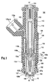
- Figure 1 illustrates a preferred embodiment of the fuel injector.
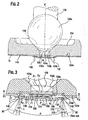
- Figure 2 illustrates a close-up cross-sectional view of an outlet end of the fuel injector of Figure 1 .
- Figure 3 illustrates a close-up cross-sectional view of an outlet end of the fuel injector of Figure 1 according to yet another preferred embodiment.
- Figs. 1-3 illustrate the preferred embodiments.
- a fuel injector 100 having a preferred embodiment of the metering disc 10 is illustrated in Fig. 1 .
- the fuel injector 100 includes: a fuel inlet tube 110, an adjustment tube 112, a filter assembly 114, a coil assembly 120, a coil spring 116, an armature 124, a closure member 126, a nonmagnetic shell 110a, a first overmold 118, a valve body 132, a valve body shell 132a, a second overmold 119, a coil assembly housing 121, a guide member 127 for the closure member 126, a seat 134, and a metering disc 10.
- the guide member 127, the seat 134, and the metering disc 10 form a stack that is coupled at the outlet end of fuel injector 100 by a suitable coupling technique, such as, for example, crimping, welding, bonding or riveting.
- Armature 124 and the closure member 126 are joined together to form an armature/needle valve assembly. It should be noted that one skilled in the art could form the assembly from a single component.
- Coil assembly 120 includes a plastic bobbin on which an electromagnetic coil 122 is wound.
- Respective terminations of coil 122 connect to respective terminals 122a, 122b that are shaped and, in cooperation with a surround 118a formed as an integral part of overmold 118, to form an electrical connector for connecting the fuel injector to an electronic control circuit (not shown) that operates the fuel injector.
- Fuel inlet tube 110 can be ferromagnetic and includes a fuel inlet opening at the exposed upper end.
- Filter assembly 114 can be fitted proximate to the open upper end of adjustment tube 112 to filter any particulate material larger than a certain size from fuel entering through inlet opening before the fuel enters adjustment tube 112.
- adjustment tube 112 has been positioned axially to an axial location within fuel inlet tube 110 that compresses preload spring 116 to a desired bias force that urges the armature/needle valve such that the rounded tip end of closure member 126 can be seated on seat 134 to close the central hole through the seat.
- tubes 110 and 112 are crimped together to maintain their relative axial positioning after adjustment calibration has been performed.
- Non-ferromagnetic shell 110a can be telescopically fitted on and joined to the lower end of inlet tube 110, as by a hermetic laser weld.
- Shell 110a has a tubular neck that telescopes over a tubular neck at the lower end of fuel inlet tube 110.
- Shell 110a also has a shoulder that extends radially outwardly from neck.
- Valve body shell 132a can be ferromagnetic and can be joined in fluid-tight manner to non-ferromagnetic shell 110a, preferably also by a hermetic laser weld.
- valve body 130 fits closely inside the lower end of valve body shell 132a and these two parts are joined together in fluid-tight manner, preferably by laser welding.
- Armature 124 can be guided by the inside wall of valve body 130 for axial reciprocation. Further axial guidance of the armature/needle valve assembly can be provided by a central guide hole in member 127 through which closure member 126 passes.
- the closure member 126 includes a spherical surface shaped member 126a disposed at one end distal to the armature.
- the spherical member 126a engages the seat 134 on seat surface 134a so as to form a generally line contact seal between the two members.
- the seat surface 134a tapers radially downward and inward toward the seat orifice 135 such that the surface 134a is oblique to the longitudinal axis A-A.
- the words “inward” and “outward” refer to directions toward and away from, respectively, the longitudinal axis A-A.
- the seal can be defined as a sealing circle 140 formed by contiguous engagement of the spherical member 126a with the seat surface 134a, shown here in Fig. 2 .
- the seat 134 includes a seat orifice 135, which extends generally along the longitudinal axis A-A of the fuel injector 100 and is formed by a generally cylindrical wall 134b.
- a center 135a of the seat orifice 135 is located generally on the longitudinal axis A-A.
- the seat 134 Downstream of the circular wall 134b, the seat 134 extends in an orthogonal manner relative to the longitudinal axis A-A to form channel surface 134d.
- the first channel surface 134d can comprise a portion curved with respect to the at least a portion of the first channel surface 134d,
- a chamfer 134c is preferably provided so as to reduce or eliminate burrs that might be formed during manufacturing of the seat 134.
- the metering disc 10 is preferably planar over its entire surface prior to being deformed so as to form a constant velocity flow channel 146 ( Fig. 3 ).
- the interior face 144 of the metering disc 10 proximate to the outer perimeter of the metering disc 10 engages the bottom surface 134e along a generally annular contact area.
- the seat orifice 135 is preferably located wholly within the perimeter, i.e., a "bolt circle" 150 defined by an imaginary line connecting a center of each of the metering orifices 142. That is, a virtual extension of the surface of the seat 135 generates a virtual orifice circle 152 that is preferably disposed within the bolt circle 150.
- the generally constant velocity flow channel 146 is formed between the seat orifice 135 of the seat 134 and interior face 134e of the metering disc 10, illustrated here in Figs. 2 and 3 .
- the channel 146 is initially formed by dimpling a surface area surrounding the bolt circle 150 in a direction downstream along the longitudinal axis A-A. This dimpling transforms a generally planar surface into a generally conic surface area 145.
- the term "dimpling" denotes that a generally material can be deformed by stamping or deep drawing a planar surface.
- a generally planar surface on which at least one metering orifice 142 is disposed thereon can be oriented along a plane C 1 and at least another metering orifice 142 can be disposed on a surface oriented along a plane C 2 oblique to a referential datum plane B-B.
- the planes C 1 and C 2 are generally symmetrical about the longitudinal axis A-A.
- each metering orifice 142 (as indicated by its metering orifice axis 170 in a pre-dimpled orientation) is re-orientated ( Fig. 3 ) such that each metering orifice 142 is no longer generally parallel to the longitudinal axis A-A (as indicated by its metering orifice axis 172 in a post-dimpled orientation).
- each metering orifice 142 is now orientated oblique to the longitudinal axis A-A at an orientation angle ⁇ .
- the channel 146 changes in cross-sectional area as the channel 146 extends outwardly from the seat orifice 135 of the seat 134 along the longitudinal axis A-A to the plurality of metering orifices 142 of the metering disc 10 such that fuel flow along the longitudinal axis through the seat orifice 135 is imparted with a radial velocity between the orifice and the plurality of metering orifices.
- dimpling of the interior surface 134e (i.e., the fuel inlet side) of the metering disc 10 tends to increase a "sac volume” between the closure member 126a and the metering disc 10.
- "Sac volume” is the small volume of fuel remaining in the interior of the tip of the injector that is believed to affect combustion and emission at the end of a fuel injection cycle.
- the surface 134f i.e. the fuel outlet side
- the sac volume reducer 160 projects toward the seat orifice 135 with a radius of curvature to reduce the interior volume between the closure member 126a and the metering disc 10, which reduced interior volume tends to reduce the sac volume.
- the sac volume reducer 160 is in the shape of a curved dome having a redefined radius of curvature.
- the sac volume reducer 160 is preferably formed such that the reducer 160 forms a perimeter 154 surrounding the virtual circle 152 on the surface 145 of the metering disc 10.
- the deformation of the surface 134e and surface 134f can be performed simultaneously or one surface can be deformed during a time interval that overlaps a time interval of the deformation of the other surface.
- the surface 134e can be deformed before the second surface 134f is deformed.
- the surface 134e is deformed before the second surface 134f is deformed.
- the channel 146 tapers outwardly from height h 1 at the seat orifice 135, as measured preferably from a position contiguous to a metering orifice 142 to referential datum plane B-B with corresponding diametrical distance D 1 to a height h 2 to referential datum plane B-B of a point on a perimeter of an area surrounding the seat orifice virtual circle 152 with corresponding diametrical distance D 2 .
- the channel surface 145 can be linear or curvilinear such that it forms a taper having an angle ⁇ between h 1 and h 2 .
- the distance h 2 is believed to be related to the taper in that the greater the height h 2 , the greater the taper angle ⁇ is required and the smaller the height h 2 , the smaller the taper angle ⁇ is required.
- An annular volume 148 that is preferably frustoconical in shape is formed between the wall surface 145 and the referential datum plane B-B.
- the velocity can decrease, increase or both increase/decrease at any point throughout the length of the channel 146, depending on the configuration of the channel, including varying D 1 , h 1 , D 2 , or h 2 of the controlled velocity channel 146, such that the product of D 1 and h 1 can be less than or greater than the product of D 2 and h 2 .
- the outward flow angle of fuel spray exiting the metering orifices 142 can be changed as a generally linear function of the radial velocity-i.e., the "linear separation angle effect.”
- the radial velocity can be changed preferably by changing the configuration of the seat subassembly, the metering disc (including D 1 , h 1 , D 2 , or h 2 of the controlled velocity channel 146), changing the flow rate of the fuel injector, or by a combination thereof.
- spray separation targeting can also be adjusted by varying a ratio of the through-length (or orifice length) "t" of each metering orifice to the diameter "D" of each orifice.
- the outward flow angle ⁇ is linearly and inversely related to the aspect ratio t/D.
- the outward flow angle ⁇ and cone size of the fuel spray are related to the aspect ratio t/D.
- the outward flow angle ⁇ and cone size increase or decrease, at different rates, correspondingly.
- the distance D is held constant, the larger the thickness "t", the smaller the outward flow angle ⁇ and cone size.
- the outward flow angle ⁇ and cone size are larger.
- spray separation can be accomplished by configuring the velocity channel 146 and space 148 while cone size and to a lesser extent, the outward flow angle ⁇ , can be accomplished by configuring the t/D ratio of the metering disc 10.
- the ratio t/D not only affects the outward flow angle, it also affects a size of the spray cone emanating from the metering orifice in a generally linear and inverse manner to the ratio t/D—i.e., the "linear and inverse separation effect.”
- the through-length "t” i.e., the length of the metering orifice along the longitudinal axis A-A
- the thickness of the metering disc can be different from the through-length t of each of the metering orifices 142.
- the term "cone size” denotes the circumference or area of the base of a fuel spray pattern defining a conic fuel spray pattern as measured at predetermined distance from the metering disc of the fuel injector 100.
- An actual separation angle can be, generally, the sum of the orientation angle ⁇ and the outward flow angle ⁇ formed by either manipulation of the channel 146 or the aspect ratio t/D of the metering disc 10.
- the orientation angle A is approximately 10 degrees.
- the term "approximately” encompasses the stated value plus or minus 25 percent ( ⁇ 25%).
- the metering disc 10 has a plurality of metering orifices 142, each metering orifice 142 having a center located on an imaginary "bolt circle" 150 prior to a deformation or dimpling of the metering disc 10.
- the metering orifices 142 are preferably circular openings, other orifice configurations, such as, for examples, square, rectangular, arcuate or slots can also be used.
- the metering orifices 142 are arrayed in a preferably circular configuration, which configuration, in one preferred embodiment, can be generally concentric with a seat orifice virtual circle 152.
- the seat orifice virtual circle 152 is formed by a virtual projection of the orifice 135 onto the metering disc 10 such that the seat orifice virtual circle 152 is within the bolt circle 150. Further, a virtual projection of the sealing surface 134a onto the metering disc 10 forms an apex "P" on the interior surface 134e of the metering disc 10 that is within the seat orifice virtual circle 152. And the preferred configuration of the seat 134, metering disc 10, metering orifices 142 and the channel 146 therebetween allows a flow path of fuel extending radially from the orifice 135 of the seat 134 in any one radial direction away from the longitudinal axis towards the metering disc passes to one metering orifice 142.
- the techniques previously described can be used to tailor the spray geometry (narrower spray pattern with greater spray angle to wider spray pattern but at a smaller spray angle) of a fuel injector to a specific engine design while using non-angled metering orifices (i.e. orifices having an axis generally parallel to the longitudinal axis A-A). Furthermore, the actual separation angle of fuel spray can be adjusted by dimpling the surface of the metering disc in two different directions along the longitudinal axis that provides for a desired separation angle and reducing the sac volume.
- the dimpling of the interior surface 134e to form the desired angle ⁇ can be done at a first time interval while the dimpling of the exterior surface 134f can be done to form the sac volume reducer 160 can be done at a second time interval that may overlap or discrete from the first time interval.
- the fuel injector 100 is initially at the non-injecting position shown in FIG. 1 .
- a working gap exists between the annular end face 110b of fuel inlet tube 110 and the confronting annular end face 124a of armature 124.
- Coil housing 121 and tube 12 are in contact at 74 and constitute a stator structure that is associated with coil assembly 18.
- Non-ferromagnetic shell 110a assures that when electromagnetic coil 122 is energized, the magnetic flux will follow a path that includes armature 124.
- the magnetic circuit extends through valve body shell 132a, valve body 130 and eyelet to armature 124, and from armature 124 across working gap 72 to inlet tube 110, and back to housing 121.
- the spring force on armature 124 can be overcome and the armature is attracted toward inlet tube 110 reducing working gap 72. This unseats closure member 126 from seat 134 open the fuel injector so that pressurized fuel in the valve body 132 flows through the seat orifice and through orifices formed on the metering disc 10, 10a, 10b or 10c.
- the actuator may be mounted such that a portion of the actuator can disposed in the fuel injector and a portion can be disposed outside the fuel injector.
Description
- This application claims the benefits of the following United States provisional patent applications:
- S.N.
60/439,059 filed on January 09, 2003 - S.N.
60/438,952, filed on January 09, 2003 - S.N.
60/439,094 filed on January 09, 2003 - Most modem automotive fuel systems utilize fuel injectors to provide precise metering of fuel for introduction into each combustion chamber. Additionally, the fuel injector atomizes the fuel during injection, breaking the fuel into a large number of very small particles, increasing the surface area of the fuel being injected, and allowing the oxidizer, typically ambient air, to more thoroughly mix with the fuel prior to combustion. The metering and atomization of the fuel reduces combustion emissions and increases the fuel efficiency of the engine. Thus, as a general rule, the greater the precision in metering and targeting of the fuel and the greater the atomization of the fuel, the lower the emissions with greater fuel efficiency.
- An electro-magnetic fuel injector typically utilizes a solenoid assembly to supply an actuating force to a fuel metering assembly. Typically, the fuel metering assembly is a plunger-style needle valve which reciprocates between a closed position, where the needle is seated in a seat to prevent fuel from escaping through a metering orifice into the combustion chamber, and an open position, where the needle is lifted from the seat, allowing fuel to discharge through the metering orifice for introduction into the combustion chamber.
- The fuel injector is typically mounted upstream of the intake valve in the intake manifold or proximate a cylinder head. As the intake valve opens on an intake port of the cylinder, fuel is sprayed towards the intake port. In one situation, it may be desirable to target the fuel spray at the intake valve head or stem while in another situation, it may be desirable to target the fuel spray at the intake port instead of at the intake valve. In both situations, the targeting of the fuel spray can be affected by the spray or cone pattern. Where the cone pattern has a large divergent cone shape, the fuel sprayed may impact on a surface of the intake port rather than towards its intended target. Conversely, where the cone pattern has a narrow divergence, the fuel may not atomize and may even recombine into a liquid stream. In either case, incomplete combustion may result, leading to an increase in undesirable exhaust emissions.
- Complicating the requirements for targeting and spray pattern is cylinder head configuration, intake geometry and intake port specific to each engine's design. As a result, a fuel injector designed for a specified cone pattern and targeting of the fuel spray may work extremely well in one type of engine configuration but may present emissions and driveability issues upon installation in a different type of engine configuration. Additionally, as more and more vehicles are produced using various configurations of engines (for example: inline-4, inline-6, V-6, V-8, V-12, W-8 etc.,), emission standards have become stricter, leading to tighter metering, spray targeting and spray or cone pattern requirements of the fuel injector for each engine configuration.
- It would be beneficial to develop a fuel injector in which increased atomization and precise targeting can be changed so as to meet a particular fuel targeting and cone pattern from one type of engine configuration to another type.
- It would also be beneficial to develop a fuel injector in which non-angled metering orifices can be used in controlling atomization, spray targeting and spray distribution of fuel.
-
EP 1 154 151 A describes a fuel injector with an annular channel between a valve seat and a metering disc, whereas said channel tapers outwardly from a large height to a smaller height toward the metering openings. - The present invention provides fuel targeting and fuel spray distribution with non-angled metering orifices. In a preferred embodiment, a fuel injector is provided. The fuel injector comprises a housing, a seat, a metering disc and a closure member. The housing has an inlet an outlet and a longitudinal axis extending therethrough. The seat is disposed proximate the outlet. The seat includes a sealing surface, an orifice, and a first channel surface. The first channel surface extends generally orthogonal to the longitudinal axis. The closure member is reciprocally located within the housing along the longitudinal axis between a first position wherein the closure member is displaced from the seat, allowing fuel flow past the closure member, and a second position wherein the closure member is biased against the seat, precluding fuel flow past the closure member. The metering disc has a plurality of metering orifices extending through the metering disc along the longitudinal axis. The metering orifices are located about the longitudinal axis on a first virtual circle greater than a second virtual circle defined by a projection of the sealing surface converging at a virtual apex disposed on the metering disc. The metering disc includes a second channel surface confronting the first channel surface. The second channel surface has at least a first surface portion generally oblique to the longitudinal axis and at least a second surface portion forming a curved surface with respect to the longitudinal axis. The controlled velocity channel is formed between the first and second channel surfaces. The controlled velocity channel has a first portion changing in cross-sectional area as the channel extends outwardly along the longitudinal axis to a location cincturing the plurality of metering orifices such that a fuel flow path exiting through each of the plurality of metering orifices forms a flow path oblique to the longitudinal axis.
- In yet another embodiment, a method of controlling a spray angle of fuel flow through at least one metering orifice of a fuel injector is provided. The fuel injector has an inlet and an outlet and a passage extending along a longitudinal axis therethrough. The outlet has a seat and a metering disc. The seat has a seat orifice and a first channel surface extending generally orthogonal to the longitudinal axis. The metering disc includes a second channel surface confronting the first channel surface. The metering disc has a plurality of metering orifices extending therethrough along the longitudinal axis and located about the longitudinal axis. The method is achieved by inducing the fuel flow to flow radially outward along the longitudinal axis between the first and second channel surfaces, the first channel surface extending generally orthogonal to the longitudinal axis; deforming a portion of the second channel surface, at a dimpling angle relative to the longitudinal axis, on which the plurality of metering orifices are located so that a flow path of the fuel flow through each of the metering orifices is oblique with respect to the longitudinal axis as a function of the radial velocity and the dimpling angle; and reducing a sac volume formed between the first channel surface and the second channel surface.
- The accompanying drawings, which are incorporated herein and constitute part of this specification, illustrate an embodiment of the invention, and, together with the general description given above and the detailed description given below, serve to explain the features of the invention.
-
Figure 1 illustrates a preferred embodiment of the fuel injector. -
Figure 2 illustrates a close-up cross-sectional view of an outlet end of the fuel injector ofFigure 1 . -
Figure 3 illustrates a close-up cross-sectional view of an outlet end of the fuel injector ofFigure 1 according to yet another preferred embodiment. -
Figs. 1-3 illustrate the preferred embodiments. In particular, afuel injector 100 having a preferred embodiment of themetering disc 10 is illustrated inFig. 1 . Thefuel injector 100 includes: afuel inlet tube 110, anadjustment tube 112, afilter assembly 114, acoil assembly 120, acoil spring 116, anarmature 124, aclosure member 126, anonmagnetic shell 110a, a first overmold 118, avalve body 132, avalve body shell 132a, a second overmold 119, acoil assembly housing 121, aguide member 127 for theclosure member 126, aseat 134, and ametering disc 10. - The
guide member 127, theseat 134, and themetering disc 10 form a stack that is coupled at the outlet end offuel injector 100 by a suitable coupling technique, such as, for example, crimping, welding, bonding or riveting.Armature 124 and theclosure member 126 are joined together to form an armature/needle valve assembly. It should be noted that one skilled in the art could form the assembly from a single component.Coil assembly 120 includes a plastic bobbin on which anelectromagnetic coil 122 is wound. - Respective terminations of
coil 122 connect torespective terminals 122a, 122b that are shaped and, in cooperation with a surround 118a formed as an integral part of overmold 118, to form an electrical connector for connecting the fuel injector to an electronic control circuit (not shown) that operates the fuel injector. -
Fuel inlet tube 110 can be ferromagnetic and includes a fuel inlet opening at the exposed upper end.Filter assembly 114 can be fitted proximate to the open upper end ofadjustment tube 112 to filter any particulate material larger than a certain size from fuel entering through inlet opening before the fuel entersadjustment tube 112. - In the calibrated fuel injector,
adjustment tube 112 has been positioned axially to an axial location withinfuel inlet tube 110 that compresses preloadspring 116 to a desired bias force that urges the armature/needle valve such that the rounded tip end ofclosure member 126 can be seated onseat 134 to close the central hole through the seat. Preferably,tubes - After passing through
adjustment tube 112, fuel enters a volume that is cooperatively defined by confronting ends ofinlet tube 110 andarmature 124 and that containspreload spring 116.Armature 124 includes apassageway 128, and guidemember 127 containsfuel passage holes volume 125 throughpassageways seat 134. -
Non-ferromagnetic shell 110a can be telescopically fitted on and joined to the lower end ofinlet tube 110, as by a hermetic laser weld.Shell 110a has a tubular neck that telescopes over a tubular neck at the lower end offuel inlet tube 110.Shell 110a also has a shoulder that extends radially outwardly from neck.Valve body shell 132a can be ferromagnetic and can be joined in fluid-tight manner tonon-ferromagnetic shell 110a, preferably also by a hermetic laser weld. - The upper end of
valve body 130 fits closely inside the lower end ofvalve body shell 132a and these two parts are joined together in fluid-tight manner, preferably by laser welding. Armature 124 can be guided by the inside wall ofvalve body 130 for axial reciprocation. Further axial guidance of the armature/needle valve assembly can be provided by a central guide hole inmember 127 through whichclosure member 126 passes. - Referring to a close up illustration of the seat subassembly of the fuel injector in
Fig. 2 , which has aclosure member 126,seat 134, and ametering disc 10. Theclosure member 126 includes a spherical surface shapedmember 126a disposed at one end distal to the armature. Thespherical member 126a engages theseat 134 onseat surface 134a so as to form a generally line contact seal between the two members. Theseat surface 134a tapers radially downward and inward toward theseat orifice 135 such that thesurface 134a is oblique to the longitudinal axis A-A. The words "inward" and "outward" refer to directions toward and away from, respectively, the longitudinal axis A-A. The seal can be defined as a sealingcircle 140 formed by contiguous engagement of thespherical member 126a with theseat surface 134a, shown here inFig. 2 . Theseat 134 includes aseat orifice 135, which extends generally along the longitudinal axis A-A of thefuel injector 100 and is formed by a generallycylindrical wall 134b. Preferably, acenter 135a of theseat orifice 135 is located generally on the longitudinal axis A-A. - Downstream of the
circular wall 134b, theseat 134 extends in an orthogonal manner relative to the longitudinal axis A-A to formchannel surface 134d. Thefirst channel surface 134d can comprise a portion curved with respect to the at least a portion of thefirst channel surface 134d, Although not required, achamfer 134c is preferably provided so as to reduce or eliminate burrs that might be formed during manufacturing of theseat 134. - Although not shown here, the
metering disc 10 is preferably planar over its entire surface prior to being deformed so as to form a constant velocity flow channel 146 (Fig. 3 ). Theinterior face 144 of themetering disc 10 proximate to the outer perimeter of themetering disc 10 engages thebottom surface 134e along a generally annular contact area. Theseat orifice 135 is preferably located wholly within the perimeter, i.e., a "bolt circle" 150 defined by an imaginary line connecting a center of each of themetering orifices 142. That is, a virtual extension of the surface of theseat 135 generates avirtual orifice circle 152 that is preferably disposed within the bolt circle 150. - The generally constant
velocity flow channel 146 is formed between theseat orifice 135 of theseat 134 andinterior face 134e of themetering disc 10, illustrated here inFigs. 2 and 3 . Specifically, thechannel 146 is initially formed by dimpling a surface area surrounding the bolt circle 150 in a direction downstream along the longitudinal axis A-A. This dimpling transforms a generally planar surface into a generallyconic surface area 145. As used herein, the term "dimpling" denotes that a generally material can be deformed by stamping or deep drawing a planar surface. That is to say, a generally planar surface on which at least onemetering orifice 142 is disposed thereon can be oriented along a plane C1 and at least anothermetering orifice 142 can be disposed on a surface oriented along a plane C2 oblique to a referential datum plane B-B. In a preferred embodiment, the planes C1 and C2 are generally symmetrical about the longitudinal axis A-A. - Due to the transformation of the initial planar surface on which the
metering orifices 142 are located on into the generallyconic surface area 145, each metering orifice 142 (as indicated by itsmetering orifice axis 170 in a pre-dimpled orientation) is re-orientated (Fig. 3 ) such that eachmetering orifice 142 is no longer generally parallel to the longitudinal axis A-A (as indicated by itsmetering orifice axis 172 in a post-dimpled orientation). As a result, eachmetering orifice 142 is now orientated oblique to the longitudinal axis A-A at an orientation angle λ. - The
channel 146 changes in cross-sectional area as thechannel 146 extends outwardly from theseat orifice 135 of theseat 134 along the longitudinal axis A-A to the plurality ofmetering orifices 142 of themetering disc 10 such that fuel flow along the longitudinal axis through theseat orifice 135 is imparted with a radial velocity between the orifice and the plurality of metering orifices. - However, dimpling of the
interior surface 134e (i.e., the fuel inlet side) of themetering disc 10 tends to increase a "sac volume" between theclosure member 126a and themetering disc 10. "Sac volume" is the small volume of fuel remaining in the interior of the tip of the injector that is believed to affect combustion and emission at the end of a fuel injection cycle. In order to reduce the "sac volume," the surface 134f (i.e. the fuel outlet side) can be dimpled towards the upstream direction with a suitable tool that preferably forms a sac volume reducer 160. The sac volume reducer 160 projects toward theseat orifice 135 with a radius of curvature to reduce the interior volume between theclosure member 126a and themetering disc 10, which reduced interior volume tends to reduce the sac volume. Preferably, the sac volume reducer 160 is in the shape of a curved dome having a redefined radius of curvature. The sac volume reducer 160 is preferably formed such that the reducer 160 forms aperimeter 154 surrounding thevirtual circle 152 on thesurface 145 of themetering disc 10. - The deformation of the
surface 134e and surface 134f can be performed simultaneously or one surface can be deformed during a time interval that overlaps a time interval of the deformation of the other surface. Alternatively, thesurface 134e can be deformed before the second surface 134f is deformed. In a preferred embodiment, thesurface 134e is deformed before the second surface 134f is deformed. - A physical representation of a particular relationship has been discovered that allows the controlled
velocity channel 146 to provide a generally constant velocity to fluid flowing through thechannel 146. In a preferred physical embodiment of this relationship, thechannel 146 tapers outwardly from height h1 at theseat orifice 135, as measured preferably from a position contiguous to ametering orifice 142 to referential datum plane B-B with corresponding diametrical distance D1 to a height h2 to referential datum plane B-B of a point on a perimeter of an area surrounding the seat orificevirtual circle 152 with corresponding diametrical distance D2. Preferably, a product of the height h1, distance D1 and π is approximately equal to the product of the height h2, distance D2 and π (i.e. D1* h1*π = D2*h2*π or D1* h1 = D2*h2) formed by theseat 134 and themetering disc 10. - The
channel surface 145 can be linear or curvilinear such that it forms a taper having an angle β between h1 and h2. The distance h2 is believed to be related to the taper in that the greater the height h2, the greater the taper angle β is required and the smaller the height h2, the smaller the taper angle β is required. Anannular volume 148 that is preferably frustoconical in shape is formed between thewall surface 145 and the referential datum plane B-B. - By providing a generally constant velocity of fuel flowing through the controlled
velocity channel 146, it is believed that a sensitivity of the position of themetering orifices 142 relative to theseat orifice 135 in spray targeting and spray distribution is minimized. That is to say, due to manufacturing tolerances, an acceptable level concentricity of the array ofmetering orifices 142 relative to theseat orifice 135 may be difficult to achieve. As such, features of the preferred embodiment are believed to provide a metering disc for a fuel injector that is believed to be less sensitive to concentricity variations between the array ofmetering orifices 142 on the bolt circle 150 and theseat orifice 135. It is also noted that those skilled in the art will recognize that from the particular relationship, the velocity can decrease, increase or both increase/decrease at any point throughout the length of thechannel 146, depending on the configuration of the channel, including varying D1, h1, D2, or h2 of the controlledvelocity channel 146, such that the product of D1 and h1 can be less than or greater than the product of D2 and h2. - By imparting a different radial velocity to fuel flowing through the
seat orifice 135, it has been discovered that the outward flow angle of fuel spray exiting themetering orifices 142 can be changed as a generally linear function of the radial velocity-i.e., the "linear separation angle effect." The radial velocity can be changed preferably by changing the configuration of the seat subassembly, the metering disc (including D1, h1, D2, or h2 of the controlled velocity channel 146), changing the flow rate of the fuel injector, or by a combination thereof. - Furthermore, it has also been discovered that spray separation targeting can also be adjusted by varying a ratio of the through-length (or orifice length) "t" of each metering orifice to the diameter "D" of each orifice. In particular, the outward flow angle θ is linearly and inversely related to the aspect ratio t/D. The outward flow angle θ and cone size of the fuel spray are related to the aspect ratio t/D. As the aspect ratio increases or decreases, the outward flow angle θ and cone size increase or decrease, at different rates, correspondingly. Where the distance D is held constant, the larger the thickness "t", the smaller the outward flow angle θ and cone size. Conversely, where the thickness "t" is smaller, the outward flow angle θ and cone size are larger. Hence, where a small cone size is desired but with a large outward flow angle, it is believed that spray separation can be accomplished by configuring the
velocity channel 146 andspace 148 while cone size and to a lesser extent, the outward flow angle θ, can be accomplished by configuring the t/D ratio of themetering disc 10. It should be reiterated that the ratio t/D not only affects the outward flow angle, it also affects a size of the spray cone emanating from the metering orifice in a generally linear and inverse manner to the ratio t/D—i.e., the "linear and inverse separation effect." Although the through-length "t" (i.e., the length of the metering orifice along the longitudinal axis A-A) is shown inFig. 3 as being substantially the same as that of the thickness of themetering disc 10, it is noted that the thickness of the metering disc can be different from the through-length t of each of themetering orifices 142. As used herein, the term "cone size" denotes the circumference or area of the base of a fuel spray pattern defining a conic fuel spray pattern as measured at predetermined distance from the metering disc of thefuel injector 100. - An actual separation angle can be, generally, the sum of the orientation angle λ and the outward flow angle θ formed by either manipulation of the
channel 146 or the aspect ratio t/D of themetering disc 10. Preferably, the orientation angle A is approximately 10 degrees. And as used herein, the term "approximately" encompasses the stated value plus or minus 25 percent (±25%). - The
metering disc 10 has a plurality ofmetering orifices 142, eachmetering orifice 142 having a center located on an imaginary "bolt circle" 150 prior to a deformation or dimpling of themetering disc 10. Although themetering orifices 142 are preferably circular openings, other orifice configurations, such as, for examples, square, rectangular, arcuate or slots can also be used. The metering orifices 142 are arrayed in a preferably circular configuration, which configuration, in one preferred embodiment, can be generally concentric with a seat orificevirtual circle 152. The seat orificevirtual circle 152 is formed by a virtual projection of theorifice 135 onto themetering disc 10 such that the seat orificevirtual circle 152 is within the bolt circle 150. Further, a virtual projection of the sealingsurface 134a onto themetering disc 10 forms an apex "P" on theinterior surface 134e of themetering disc 10 that is within the seat orificevirtual circle 152. And the preferred configuration of theseat 134,metering disc 10,metering orifices 142 and thechannel 146 therebetween allows a flow path of fuel extending radially from theorifice 135 of theseat 134 in any one radial direction away from the longitudinal axis towards the metering disc passes to onemetering orifice 142. - Thus, it has been discovered that manipulation of at least one of either the taper of the
flow channel 146 or the ratio t/D allows ametering orifice 142 to provide for an actual separation angle that is greater than an orientation angle λ of themetering orifice 142. - The techniques previously described can be used to tailor the spray geometry (narrower spray pattern with greater spray angle to wider spray pattern but at a smaller spray angle) of a fuel injector to a specific engine design while using non-angled metering orifices (i.e. orifices having an axis generally parallel to the longitudinal axis A-A). Furthermore, the actual separation angle of fuel spray can be adjusted by dimpling the surface of the metering disc in two different directions along the longitudinal axis that provides for a desired separation angle and reducing the sac volume. And the dimpling of the
interior surface 134e to form the desired angle λ can be done at a first time interval while the dimpling of the exterior surface 134f can be done to form the sac volume reducer 160 can be done at a second time interval that may overlap or discrete from the first time interval. - In operation, the
fuel injector 100 is initially at the non-injecting position shown inFIG. 1 . In this position, a working gap exists between theannular end face 110b offuel inlet tube 110 and the confrontingannular end face 124a ofarmature 124.Coil housing 121 and tube 12 are in contact at 74 and constitute a stator structure that is associated with coil assembly 18.Non-ferromagnetic shell 110a assures that whenelectromagnetic coil 122 is energized, the magnetic flux will follow a path that includesarmature 124. Starting at the lower axial end of housing 34, where it is joined withvalve body shell 132a by a hermetic laser weld, the magnetic circuit extends throughvalve body shell 132a,valve body 130 and eyelet toarmature 124, and fromarmature 124 across working gap 72 toinlet tube 110, and back tohousing 121. - When
electromagnetic coil 122 is energized, the spring force onarmature 124 can be overcome and the armature is attracted towardinlet tube 110 reducing working gap 72. This unseatsclosure member 126 fromseat 134 open the fuel injector so that pressurized fuel in thevalve body 132 flows through the seat orifice and through orifices formed on themetering disc 10, 10a, 10b or 10c. It should be noted here that the actuator may be mounted such that a portion of the actuator can disposed in the fuel injector and a portion can be disposed outside the fuel injector. When the coil ceases to be energized,preload spring 116 pushes the armature/needle valve closed onseat 134.
Claims (16)
- A fuel injector (100) comprising:a housing having an inlet, an outlet, and a longitudinal axis (A) extending therethrough;a seat (134) disposed proximate the outlet, the seat (134) having a sealing surface (134a) surrounding a seat orifice (135), the seat orifice (135) being disposed along the longitudinal axis (A) between the sealing surface (134a) and a first channel surface (134d) extending generally orthogonal about the longitudinal axis (A);a closure member (126) reciprocally located within the housing along the longitudinal axis (A) between a first position displaced from the sealing surface (134a) to permit fuel flow through the seat orifice (135) and a second position of the closure member (126) contiguous to the sealing surface (134a) to occlude fuel flow;a metering disc (10) having a plurality of metering orifices (142) extending through the metering disc (10) along the longitudinal axis (A), the metering orifices (142) being located about the longitudinal axis (A) on a first virtual circle greater than a second virtual circle defined by a projection of the sealing surface (134a) converging at a virtual apex disposed on the metering disc (10), the metering disc (10) including a second channel surface confronting the first channel surface (134d), the second channel surface having at least a portion (145) generally oblique to the longitudinal axis (A) and at least a portion forming curved surface with respect to the longitudinal axis (A); anda controlled velocity channel (146) formed between the first and second channel surfaces, the controlled velocity channel (146) having a first portion changing in cross-sectional area as the channel (146) extends outwardly along the longitudinal axis (A) to a location cincturing the plurality of metering orifices (142) such that a fuel flow path exiting through each of the plurality of metering orifices (142) forms a flow path oblique to the longitudinal axis (A) characterized in thatthe curved surface projects towards the seat orifices (135) to reduce a volume formed between the closure member (126) and the metering disc (10) when the closure member (126) is contiguous to the sealing surface (134a) of the seat (134).
- The fuel injector (100) of claim 1, wherein the controlled velocity channel (146) extends between a first end and a second end, the first end disposed at a first radius from the longitudinal axis (A) with the first (134d) and second channel surfaces spaced apart along the longitudinal axis (A) at a first distance, the second end disposed at a second radius proximate the plurality of metering orifices (142) with respect to the longitudinal axis (A) with the first (134d) and second channel surfaces spaced apart along the longitudinal axis (A) at a second distance such that a product of two times the trigonometric constant pi (π) times the first radius and the first distance is equal to a product of two times the trigonometric constant pi (π) of the second radius and the second distance.
- The fuel injector (100) of claim 2, wherein the plurality of metering orifices (142) includes at least two metering orifices (142) diametrically disposed on the first virtual circle.
- The fuel injector (100) of claim 1, wherein the plurality of metering orifices (142) includes at least two metering orifices (142), each metering orifice (142) having a through-length (t) and an orifice diameter (D) and being configured such that an increase in a ratio of the through-length (t) relative to the orifice diameter (D) results in a decrease in the spray angle relative to the longitudinal axis (A).
- The fuel injector (100) of claim 1, wherein the plurality of metering orifices (142) includes at least two metering orifices (142), each metering orifice (142) having a through-length (t) and an orifice diameter (D) and being configured such that an increase in a ratio of the through-length (t) relative to the orifice diameter (D) results in a decrease in an included angle of a spray cone produced by each metering orifice (142).
- The fuel injector (100) of claim 5, wherein second channel surface comprises a first generally planar surface portion cincturing second and third surface portions, the second and third surface portions projecting from the plane contiguous to the first generally planar surface portion.
- The fuel injector (100) of claim 6, wherein the second surface portion comprises at least one conic surface.
- The fuel injector (100) of claim 7, wherein the third surface portion intersects the longitudinal axis (A).
- The fuel injector (100) of claim 8, wherein the third surface portion projects towards the seat orifice (135) to reduce a volume formed between the closure member (126) and the metering disc (10) when the closure member (126) is contiguous to the sealing surface (134a) of the seat (134).
- The fuel injector (100) of claim 9, wherein the third surface portion intersects the second surface portion to define a generally circular perimeter defining an area equal to the area of the seat orifice (135) orthogonally with respect to the longitudinal axis (A).
- The fuel injector (100) of claim 10, wherein the area of the generally circular perimeter is less than the area of the seat orifice (135).
- The fuel injector (100) of claim 8, wherein the plurality of metering orifices. (142) is disposed on the at least one planar surface of the second surface portion.
- The fuel injector (100) of claim 9, wherein the first channel surface (134d) includes at least a portion extending at a taper angle with respect to the longitudinal axis (A).
- The fuel injector (100) of claim 10, wherein the taper angle comprises a taper angle of approximately ten degrees with respect to a plane transverse to the longitudinal axis.
- The fuel injector (100) of claim 11, wherein the first channel surface (134d) comprises a portion curved with respect to the at least a portion of the first channel surface (134d).
- A method of controlling a spray angle of fuel flow through at least one metering orifice (142) using a fuel injector (100) as claimed in any one of the preceding claims.
Applications Claiming Priority (7)
| Application Number | Priority Date | Filing Date | Title |
|---|---|---|---|
| US43905903P | 2003-01-09 | 2003-01-09 | |
| US43895203P | 2003-01-09 | 2003-01-09 | |
| US43909403P | 2003-01-09 | 2003-01-09 | |
| US439094P | 2003-01-09 | ||
| US438952P | 2003-01-09 | ||
| US439059P | 2003-01-09 | ||
| PCT/US2004/000594 WO2004063556A2 (en) | 2003-01-09 | 2004-01-09 | Spray pattern control with non-angled orifices formed on a dimpled fuel injection metering disc having a sac volume reducer |
Publications (2)
| Publication Number | Publication Date |
|---|---|
| EP1581737A2 EP1581737A2 (en) | 2005-10-05 |
| EP1581737B1 true EP1581737B1 (en) | 2009-05-27 |
Family
ID=32719198
Family Applications (3)
| Application Number | Title | Priority Date | Filing Date |
|---|---|---|---|
| EP04701235A Expired - Fee Related EP1581737B1 (en) | 2003-01-09 | 2004-01-09 | Spray pattern control with non-angled orifices formed on a dimpled fuel injection metering disc having a sac volume reducer |
| EP04701241A Expired - Fee Related EP1581738B1 (en) | 2003-01-09 | 2004-01-09 | Spray pattern control with non-angled orifices formed on a generally planar metering disc and reoriented on subsequently dimpled fuel injection metering disc |
| EP04701255A Expired - Fee Related EP1581739B1 (en) | 2003-01-09 | 2004-01-09 | Spray pattern control with non-angled orifices formed on dimpled fuel injection metering disc having a sac volume reducer |
Family Applications After (2)
| Application Number | Title | Priority Date | Filing Date |
|---|---|---|---|
| EP04701241A Expired - Fee Related EP1581738B1 (en) | 2003-01-09 | 2004-01-09 | Spray pattern control with non-angled orifices formed on a generally planar metering disc and reoriented on subsequently dimpled fuel injection metering disc |
| EP04701255A Expired - Fee Related EP1581739B1 (en) | 2003-01-09 | 2004-01-09 | Spray pattern control with non-angled orifices formed on dimpled fuel injection metering disc having a sac volume reducer |
Country Status (5)
| Country | Link |
|---|---|
| US (3) | US6921021B2 (en) |
| EP (3) | EP1581737B1 (en) |
| JP (3) | JP2006515402A (en) |
| DE (3) | DE602004002558T2 (en) |
| WO (3) | WO2004063556A2 (en) |
Families Citing this family (42)
| Publication number | Priority date | Publication date | Assignee | Title |
|---|---|---|---|---|
| US6742727B1 (en) * | 2000-05-10 | 2004-06-01 | Siemens Automotive Corporation | Injection valve with single disc turbulence generation |
| JP2005143111A (en) * | 2003-11-07 | 2005-06-02 | Siemens Ag | Method for operating telephone facility in domestic range and telephone facility for implementing the method |
| US7201329B2 (en) * | 2004-04-30 | 2007-04-10 | Siemens Vdo Automotive Corporation | Fuel injector including a compound angle orifice disc for adjusting spray targeting |
| DE102004049281A1 (en) * | 2004-10-09 | 2006-04-20 | Robert Bosch Gmbh | Fuel injector |
| US7051957B1 (en) * | 2004-11-05 | 2006-05-30 | Visteon Global Technologies, Inc. | Low pressure fuel injector nozzle |
| US7168637B2 (en) * | 2004-11-05 | 2007-01-30 | Visteon Global Technologies, Inc. | Low pressure fuel injector nozzle |
| US7198207B2 (en) * | 2004-11-05 | 2007-04-03 | Visteon Global Technologies, Inc. | Low pressure fuel injector nozzle |
| US7137577B2 (en) | 2004-11-05 | 2006-11-21 | Visteon Global Technologies, Inc. | Low pressure fuel injector nozzle |
| US7104475B2 (en) * | 2004-11-05 | 2006-09-12 | Visteon Global Technologies, Inc. | Low pressure fuel injector nozzle |
| US7438241B2 (en) * | 2004-11-05 | 2008-10-21 | Visteon Global Technologies, Inc. | Low pressure fuel injector nozzle |
| US7124963B2 (en) | 2004-11-05 | 2006-10-24 | Visteon Global Technologies, Inc. | Low pressure fuel injector nozzle |
| US20060157595A1 (en) * | 2005-01-14 | 2006-07-20 | Peterson William A Jr | Fuel injector for high fuel flow rate applications |
| US20080185460A1 (en) * | 2005-07-29 | 2008-08-07 | Mitsubishi Electric Corporation | Fuel Injection Valve |
| JP4218696B2 (en) * | 2006-05-19 | 2009-02-04 | トヨタ自動車株式会社 | Fuel injection nozzle |
| EP1882844A1 (en) * | 2006-07-25 | 2008-01-30 | Siemens Aktiengesellschaft | Valve assembly for an Injection valve and injection valve |
| JP4555955B2 (en) * | 2006-10-19 | 2010-10-06 | 日立オートモティブシステムズ株式会社 | Fuel injection valve and internal combustion engine equipped with the same |
| JP4296519B2 (en) | 2006-12-19 | 2009-07-15 | 株式会社日立製作所 | Fuel injection valve |
| WO2008093387A1 (en) * | 2007-01-29 | 2008-08-07 | Mitsubishi Electric Corporation | Fuel injection valve |
| WO2008117459A1 (en) * | 2007-03-27 | 2008-10-02 | Mitsubishi Electric Corporation | Fuel injection valve |
| US7669789B2 (en) * | 2007-08-29 | 2010-03-02 | Visteon Global Technologies, Inc. | Low pressure fuel injector nozzle |
| US20090057446A1 (en) * | 2007-08-29 | 2009-03-05 | Visteon Global Technologies, Inc. | Low pressure fuel injector nozzle |
| US20090090794A1 (en) * | 2007-10-04 | 2009-04-09 | Visteon Global Technologies, Inc. | Low pressure fuel injector |
| US20090200403A1 (en) * | 2008-02-08 | 2009-08-13 | David Ling-Shun Hung | Fuel injector |
| US20100314470A1 (en) * | 2009-06-11 | 2010-12-16 | Stanadyne Corporation | Injector having swirl structure downstream of valve seat |
| US8794550B2 (en) | 2010-03-05 | 2014-08-05 | Toyota Jidosha Kabushiki Kaisha | Fuel injection valve |
| EP2657509B1 (en) * | 2010-12-20 | 2016-08-24 | Toyota Jidosha Kabushiki Kaisha | Fuel injection valve |
| JP5668984B2 (en) * | 2011-05-31 | 2015-02-12 | 株式会社デンソー | Fuel injection device |
| CN104334865A (en) * | 2012-05-11 | 2015-02-04 | 丰田自动车株式会社 | Fuel injection valve and fuel injection device with same |
| DE102012210962A1 (en) * | 2012-06-27 | 2014-01-02 | Robert Bosch Gmbh | Fuel injector |
| US20150211458A1 (en) * | 2012-08-01 | 2015-07-30 | 3M Innovative Properties Company | Targeting of fuel output by off-axis directing of nozzle output streams |
| DE102013212191A1 (en) * | 2013-06-26 | 2014-12-31 | Robert Bosch Gmbh | Method and device for injecting a gaseous medium |
| JP6168936B2 (en) * | 2013-09-11 | 2017-07-26 | 日立オートモティブシステムズ株式会社 | Fuel injection valve |
| DE102013225948A1 (en) * | 2013-12-13 | 2015-06-18 | Continental Automotive Gmbh | Nozzle head and fluid injection valve |
| JP6501500B2 (en) * | 2014-11-11 | 2019-04-17 | 日立オートモティブシステムズ株式会社 | Fuel injection valve |
| JP6365450B2 (en) * | 2015-07-24 | 2018-08-01 | 株式会社デンソー | Fuel injection device |
| CN109072848A (en) * | 2015-10-16 | 2018-12-21 | 秘方能源私人有限公司 | Improve the tradition directly method of injector and improved injector assembly |
| DE102015226769A1 (en) * | 2015-12-29 | 2017-06-29 | Robert Bosch Gmbh | Fuel injector |
| US10865754B2 (en) | 2017-04-05 | 2020-12-15 | Progress Rail Services Corporation | Fuel injector having needle tip and nozzle body surfaces structured for reduced sac volume and fracture resistance |
| JP7206601B2 (en) * | 2018-03-08 | 2023-01-18 | 株式会社デンソー | Fuel injection valve and fuel injection system |
| US11253875B2 (en) * | 2018-07-27 | 2022-02-22 | Vitesco Technologies USA, LLC | Multi-dimple orifice disc for a fluid injector, and methods for constructing and utilizing same |
| US10895231B2 (en) | 2019-06-13 | 2021-01-19 | Progress Rail Services Corporation | Fuel injector nozzle assembly having anti-cavitation vent and method |
| EP3851663A1 (en) * | 2020-01-17 | 2021-07-21 | Vitesco Technologies GmbH | Valve seat body assembly for a fluid injector of an internal combustion engine with a valve seat body and an orifice part |
Family Cites Families (59)
| Publication number | Priority date | Publication date | Assignee | Title |
|---|---|---|---|---|
| US600687A (en) * | 1898-03-15 | Holes in brush backs by pressure | ||
| US335334A (en) * | 1886-02-02 | Method of making dies | ||
| US2737831A (en) * | 1950-06-02 | 1956-03-13 | American Viscose Corp | Process for making a spinneret |
| US2846902A (en) * | 1956-02-06 | 1958-08-12 | American Saw & Tool Company | Drill elements |
| JPS5232192A (en) | 1975-09-06 | 1977-03-11 | Yamamoto Seisakusho:Kk | Through hole boring method for flat heat screw |
| JPS52132490A (en) * | 1976-04-30 | 1977-11-07 | Yoshitaka Nakanishi | Method of sinking counter sink in plate blank |
| US4057190A (en) | 1976-06-17 | 1977-11-08 | Bendix Corporation | Fuel break-up disc for injection valve |
| US4101074A (en) | 1976-06-17 | 1978-07-18 | The Bendix Corporation | Fuel inlet assembly for a fuel injection valve |
| DE3229716C2 (en) * | 1982-08-10 | 1995-01-26 | Bosch Gmbh Robert | Fuel injector |
| JPS59223121A (en) | 1983-06-01 | 1984-12-14 | Miyagi Seiki Kk | Die set |
| JPS60137529A (en) | 1983-12-27 | 1985-07-22 | Amada Metoretsukusu:Kk | Method for forming countersink of platelike member |
| US4621772A (en) * | 1985-05-06 | 1986-11-11 | General Motors Corporation | Electromagnetic fuel injector with thin orifice director plate |
| US4970926A (en) | 1987-09-17 | 1990-11-20 | Neurodynamics, Inc. | Apparatus for making angled hole ventricular catheter |
| US4923169A (en) * | 1987-12-23 | 1990-05-08 | Siemens-Bendix Automotive Electronics L.P. | Multi-stream thin edge orifice disks for valves |
| DE8802464U1 (en) | 1988-02-25 | 1989-06-22 | Robert Bosch Gmbh, 7000 Stuttgart, De | |
| DE3841142C2 (en) * | 1988-12-07 | 1994-09-29 | Bosch Gmbh Robert | Injector |
| DE3919231C2 (en) * | 1989-06-13 | 1997-03-06 | Bosch Gmbh Robert | Fuel injection device for internal combustion engines |
| DE4104019C1 (en) * | 1991-02-09 | 1992-04-23 | Robert Bosch Gmbh, 7000 Stuttgart, De | |
| US5367057A (en) * | 1991-04-02 | 1994-11-22 | The Trustees Of Princeton University | Tyrosine kinase receptor flk-2 and fragments thereof |
| US5201806A (en) * | 1991-06-17 | 1993-04-13 | Siemens Automotive L.P. | Tilted fuel injector having a thin disc orifice member |
| DE4123692C2 (en) * | 1991-07-17 | 1995-01-26 | Bosch Gmbh Robert | Fuel injector |
| EP0636210B1 (en) | 1992-04-01 | 1996-12-11 | Siemens Automotive Corporation | Injector valve seat with recirculation trap |
| US5365819B1 (en) | 1992-12-22 | 1997-04-22 | Prompac Ind Inc | Method and process for manufacturing expandable packing material |
| DE4406846C1 (en) * | 1994-03-03 | 1995-05-04 | Koenig & Bauer Ag | Device for drying printed sheets or webs in printing machines |
| WO1995004881A1 (en) * | 1993-08-06 | 1995-02-16 | Ford Motor Company | A fuel injector |
| DE4328418A1 (en) | 1993-08-24 | 1995-03-02 | Bosch Gmbh Robert | Solenoid fuel injection valve |
| CN1050649C (en) | 1993-12-21 | 2000-03-22 | 罗伯特·博施有限公司 | Venturi filter and fuel injection valve with a venturi filter |
| JPH07279796A (en) * | 1994-02-16 | 1995-10-27 | Nippondenso Co Ltd | Fluid injection nozzle and its manufacture |
| JP3440534B2 (en) * | 1994-03-03 | 2003-08-25 | 株式会社デンソー | Fluid injection nozzle |
| US5484108A (en) * | 1994-03-31 | 1996-01-16 | Siemens Automotive L.P. | Fuel injector having novel multiple orifice disk members |
| DE19523165B4 (en) | 1994-06-29 | 2005-11-17 | Bosch Automotive Systems Corp. | fuel Injector |
| US5489065A (en) | 1994-06-30 | 1996-02-06 | Siemens Automotive L.P. | Thin disk orifice member for fuel injector |
| CH688306A5 (en) * | 1994-09-07 | 1997-07-31 | Eugen Haenggi | Method and apparatus for punching Loechernin a flat workpiece. |
| JP2935817B2 (en) | 1994-09-29 | 1999-08-16 | 日東工器株式会社 | Hole forming method for forming a tapered through hole in a workpiece by pressing and tool for forming the hole |
| DE4435163A1 (en) * | 1994-09-30 | 1996-04-04 | Bosch Gmbh Robert | Nozzle plate, in particular for injection valves and methods for producing a nozzle plate |
| DE4445358A1 (en) * | 1994-12-20 | 1996-06-27 | Bosch Gmbh Robert | Valve and method of making a valve |
| DE19503269A1 (en) * | 1995-02-02 | 1996-08-08 | Bosch Gmbh Robert | Fuel injection valve for internal combustion engines |
| ES2179184T3 (en) * | 1995-03-29 | 2003-01-16 | Bosch Gmbh Robert | PROCEDURE FOR THE MANUFACTURE OF A PERFORATED DISC. |
| JP3156554B2 (en) | 1995-07-24 | 2001-04-16 | トヨタ自動車株式会社 | Fuel injection valve |
| DE19527626A1 (en) | 1995-07-28 | 1997-01-30 | Bosch Gmbh Robert | Fuel injector |
| US5644081A (en) * | 1995-09-28 | 1997-07-01 | Delco Electronics Corp. | Microaccelerometer package with integral support braces |
| FR2743710B1 (en) * | 1996-01-24 | 1998-02-27 | Seb Sa | MULTI-PURPOSE ROBOT HOUSEHOLD APPLIANCES FOR CULINARY PREPARATION, INCLUDING A SUPPORT FOR THE ROTARY WORK UNIT |
| DE19631066A1 (en) * | 1996-08-01 | 1998-02-05 | Bosch Gmbh Robert | Fuel injector |
| JPH10122096A (en) | 1996-10-16 | 1998-05-12 | Aisan Ind Co Ltd | Fuel injection valve |
| US5916093A (en) * | 1996-10-24 | 1999-06-29 | American Composite Material Engineering, Inc. | Composite fiberglass railcar roof |
| JP3750768B2 (en) * | 1996-10-25 | 2006-03-01 | 株式会社デンソー | Fluid injection nozzle |
| DE19653832A1 (en) | 1996-12-21 | 1998-06-25 | Bosch Gmbh Robert | Valve with combined valve seat body and spray orifice plate |
| DE19703200A1 (en) * | 1997-01-30 | 1998-08-06 | Bosch Gmbh Robert | Fuel injector |
| JP3164023B2 (en) * | 1997-06-25 | 2001-05-08 | トヨタ自動車株式会社 | Fuel injection valve for internal combustion engine |
| JP3777259B2 (en) | 1998-09-24 | 2006-05-24 | 株式会社ケーヒン | Electromagnetic fuel injection valve |
| US6102299A (en) * | 1998-12-18 | 2000-08-15 | Siemens Automotive Corporation | Fuel injector with impinging jet atomizer |
| US6330981B1 (en) | 1999-03-01 | 2001-12-18 | Siemens Automotive Corporation | Fuel injector with turbulence generator for fuel orifice |
| JP2001027169A (en) | 1999-07-15 | 2001-01-30 | Unisia Jecs Corp | Fuel injection valve |
| JP2001046919A (en) * | 1999-08-06 | 2001-02-20 | Denso Corp | Fluid injection nozzle |
| US6357677B1 (en) | 1999-10-13 | 2002-03-19 | Siemens Automotive Corporation | Fuel injection valve with multiple nozzle plates |
| US6742727B1 (en) * | 2000-05-10 | 2004-06-01 | Siemens Automotive Corporation | Injection valve with single disc turbulence generation |
| JP2002039036A (en) * | 2000-07-24 | 2002-02-06 | Mitsubishi Electric Corp | Fuel injection valve |
| JP3837282B2 (en) * | 2000-10-24 | 2006-10-25 | 株式会社ケーヒン | Fuel injection valve |
| DE10059007A1 (en) | 2000-11-28 | 2002-05-29 | Bosch Gmbh Robert | Fuel injector |
-
2004
- 2004-01-09 WO PCT/US2004/000594 patent/WO2004063556A2/en active Search and Examination
- 2004-01-09 DE DE602004002558T patent/DE602004002558T2/en not_active Expired - Lifetime
- 2004-01-09 JP JP2006500889A patent/JP2006515402A/en active Pending
- 2004-01-09 US US10/753,377 patent/US6921021B2/en not_active Expired - Lifetime
- 2004-01-09 DE DE602004021231T patent/DE602004021231D1/en not_active Expired - Lifetime
- 2004-01-09 DE DE602004020970T patent/DE602004020970D1/en not_active Expired - Lifetime
- 2004-01-09 WO PCT/US2004/000593 patent/WO2004063555A1/en active Search and Examination
- 2004-01-09 JP JP2005518796A patent/JP4192179B2/en not_active Expired - Fee Related
- 2004-01-09 US US10/753,481 patent/US6966499B2/en not_active Expired - Lifetime
- 2004-01-09 JP JP2005518797A patent/JP4226604B2/en not_active Expired - Fee Related
- 2004-01-09 EP EP04701235A patent/EP1581737B1/en not_active Expired - Fee Related
- 2004-01-09 EP EP04701241A patent/EP1581738B1/en not_active Expired - Fee Related
- 2004-01-09 WO PCT/US2004/000518 patent/WO2004063554A2/en active IP Right Grant
- 2004-01-09 US US10/753,378 patent/US6921022B2/en not_active Expired - Lifetime
- 2004-01-09 EP EP04701255A patent/EP1581739B1/en not_active Expired - Fee Related
Also Published As
| Publication number | Publication date |
|---|---|
| JP4192179B2 (en) | 2008-12-03 |
| DE602004002558T2 (en) | 2007-10-25 |
| JP2006515402A (en) | 2006-05-25 |
| EP1581739B1 (en) | 2006-09-27 |
| WO2004063554A2 (en) | 2004-07-29 |
| WO2004063556A2 (en) | 2004-07-29 |
| WO2004063554A3 (en) | 2004-09-02 |
| EP1581737A2 (en) | 2005-10-05 |
| EP1581738A1 (en) | 2005-10-05 |
| EP1581738B1 (en) | 2009-05-06 |
| EP1581739A2 (en) | 2005-10-05 |
| WO2004063556A3 (en) | 2004-11-04 |
| US20040217207A1 (en) | 2004-11-04 |
| DE602004002558D1 (en) | 2006-11-09 |
| DE602004021231D1 (en) | 2009-07-09 |
| US6921022B2 (en) | 2005-07-26 |
| JP4226604B2 (en) | 2009-02-18 |
| US6921021B2 (en) | 2005-07-26 |
| US20040217213A1 (en) | 2004-11-04 |
| DE602004020970D1 (en) | 2009-06-18 |
| US6966499B2 (en) | 2005-11-22 |
| WO2004063555A1 (en) | 2004-07-29 |
| US20040217208A1 (en) | 2004-11-04 |
| JP2006514724A (en) | 2006-05-11 |
| JP2006513371A (en) | 2006-04-20 |
Similar Documents
| Publication | Publication Date | Title |
|---|---|---|
| EP1581737B1 (en) | Spray pattern control with non-angled orifices formed on a dimpled fuel injection metering disc having a sac volume reducer | |
| EP1392968B1 (en) | Spray pattern control with non-angled orifices in fuel injection metering disc | |
| US7159800B2 (en) | Spray pattern control with angular orientation in fuel injector and method | |
| US20050087629A1 (en) | Fuel injector with sauter-mean-diameter atomization spray of less than 70 microns | |
| US6966505B2 (en) | Spray control with non-angled orifices in fuel injection metering disc and methods | |
| US6929197B2 (en) | Generally circular spray pattern control with non-angled orifices in fuel injection metering disc and method | |
| US7048202B2 (en) | Compound-angled orifices in fuel injection metering disc | |
| EP1375903B1 (en) | Spray pattern and spray distribution control with non-angled orifices in fuel injection metering disc and methods | |
| US20060157595A1 (en) | Fuel injector for high fuel flow rate applications | |
| US6820826B2 (en) | Spray targeting to an arcuate sector with non-angled orifices in fuel injection metering disc and method | |
| US7334746B2 (en) | Seat-lower guide combination | |
| EP1856404B1 (en) | Seat-lower guide combination |
Legal Events
| Date | Code | Title | Description |
|---|---|---|---|
| PUAI | Public reference made under article 153(3) epc to a published international application that has entered the european phase |
Free format text: ORIGINAL CODE: 0009012 |
|
| 17P | Request for examination filed |
Effective date: 20050526 |
|
| AK | Designated contracting states |
Kind code of ref document: A2 Designated state(s): AT BE BG CH CY CZ DE DK EE ES FI FR GB GR HU IE IT LI LU MC NL PT RO SE SI SK TR |
|
| AX | Request for extension of the european patent |
Extension state: AL LT LV MK |
|
| DAX | Request for extension of the european patent (deleted) | ||
| RBV | Designated contracting states (corrected) |
Designated state(s): DE FR |
|
| RAP1 | Party data changed (applicant data changed or rights of an application transferred) |
Owner name: CONTINENTAL AUTOMOTIVE SYSTEMS US, INC. |
|
| GRAP | Despatch of communication of intention to grant a patent |
Free format text: ORIGINAL CODE: EPIDOSNIGR1 |
|
| GRAS | Grant fee paid |
Free format text: ORIGINAL CODE: EPIDOSNIGR3 |
|
| GRAA | (expected) grant |
Free format text: ORIGINAL CODE: 0009210 |
|
| AK | Designated contracting states |
Kind code of ref document: B1 Designated state(s): DE FR |
|
| REF | Corresponds to: |
Ref document number: 602004021231 Country of ref document: DE Date of ref document: 20090709 Kind code of ref document: P |
|
| PLBE | No opposition filed within time limit |
Free format text: ORIGINAL CODE: 0009261 |
|
| STAA | Information on the status of an ep patent application or granted ep patent |
Free format text: STATUS: NO OPPOSITION FILED WITHIN TIME LIMIT |
|
| 26N | No opposition filed |
Effective date: 20100302 |
|
| PGFP | Annual fee paid to national office [announced via postgrant information from national office to epo] |
Ref country code: FR Payment date: 20100223 Year of fee payment: 7 |
|
| REG | Reference to a national code |
Ref country code: FR Ref legal event code: ST Effective date: 20110930 |
|
| PG25 | Lapsed in a contracting state [announced via postgrant information from national office to epo] |
Ref country code: FR Free format text: LAPSE BECAUSE OF NON-PAYMENT OF DUE FEES Effective date: 20110131 |
|
| REG | Reference to a national code |
Ref country code: DE Ref legal event code: R081 Ref document number: 602004021231 Country of ref document: DE Owner name: CONTINENTAL AUTOMOTIVE SYSTEMS, INC. ( N. D. G, US Free format text: FORMER OWNER: CONTINENTAL AUTOMOTIVE SYSTEMS US, INC., AUBURN HILLS, US Effective date: 20140317 Ref country code: DE Ref legal event code: R081 Ref document number: 602004021231 Country of ref document: DE Owner name: CONTINENTAL AUTOMOTIVE SYSTEMS, INC. ( N. D. G, US Free format text: FORMER OWNER: CONTINENTAL AUTOMOTIVE SYSTEMS US, INC., AUBURN HILLS, MICH., US Effective date: 20140317 |
|
| PGFP | Annual fee paid to national office [announced via postgrant information from national office to epo] |
Ref country code: DE Payment date: 20180131 Year of fee payment: 15 |
|
| REG | Reference to a national code |
Ref country code: DE Ref legal event code: R119 Ref document number: 602004021231 Country of ref document: DE |
|
| PG25 | Lapsed in a contracting state [announced via postgrant information from national office to epo] |
Ref country code: DE Free format text: LAPSE BECAUSE OF NON-PAYMENT OF DUE FEES Effective date: 20190801 |