EP1882108B1 - Forged roller - Google Patents
Forged roller Download PDFInfo
- Publication number
- EP1882108B1 EP1882108B1 EP05770490.0A EP05770490A EP1882108B1 EP 1882108 B1 EP1882108 B1 EP 1882108B1 EP 05770490 A EP05770490 A EP 05770490A EP 1882108 B1 EP1882108 B1 EP 1882108B1
- Authority
- EP
- European Patent Office
- Prior art keywords
- blank
- die
- tool
- set forth
- roller
- Prior art date
- Legal status (The legal status is an assumption and is not a legal conclusion. Google has not performed a legal analysis and makes no representation as to the accuracy of the status listed.)
- Expired - Lifetime
Links
Images



Classifications
-
- F—MECHANICAL ENGINEERING; LIGHTING; HEATING; WEAPONS; BLASTING
- F16—ENGINEERING ELEMENTS AND UNITS; GENERAL MEASURES FOR PRODUCING AND MAINTAINING EFFECTIVE FUNCTIONING OF MACHINES OR INSTALLATIONS; THERMAL INSULATION IN GENERAL
- F16C—SHAFTS; FLEXIBLE SHAFTS; ELEMENTS OR CRANKSHAFT MECHANISMS; ROTARY BODIES OTHER THAN GEARING ELEMENTS; BEARINGS
- F16C33/00—Parts of bearings; Special methods for making bearings or parts thereof
- F16C33/30—Parts of ball or roller bearings
- F16C33/34—Rollers; Needles
- F16C33/36—Rollers; Needles with bearing-surfaces other than cylindrical, e.g. tapered; with grooves in the bearing surfaces
-
- B—PERFORMING OPERATIONS; TRANSPORTING
- B21—MECHANICAL METAL-WORKING WITHOUT ESSENTIALLY REMOVING MATERIAL; PUNCHING METAL
- B21J—FORGING; HAMMERING; PRESSING METAL; RIVETING; FORGE FURNACES
- B21J13/00—Details of machines for forging, pressing, or hammering
- B21J13/02—Dies or mountings therefor
- B21J13/03—Die mountings
-
- B—PERFORMING OPERATIONS; TRANSPORTING
- B21—MECHANICAL METAL-WORKING WITHOUT ESSENTIALLY REMOVING MATERIAL; PUNCHING METAL
- B21J—FORGING; HAMMERING; PRESSING METAL; RIVETING; FORGE FURNACES
- B21J5/00—Methods for forging, hammering, or pressing; Special equipment or accessories therefor
- B21J5/02—Die forging; Trimming by making use of special dies ; Punching during forging
-
- B—PERFORMING OPERATIONS; TRANSPORTING
- B21—MECHANICAL METAL-WORKING WITHOUT ESSENTIALLY REMOVING MATERIAL; PUNCHING METAL
- B21J—FORGING; HAMMERING; PRESSING METAL; RIVETING; FORGE FURNACES
- B21J9/00—Forging presses
- B21J9/02—Special design or construction
- B21J9/022—Special design or construction multi-stage forging presses
-
- B—PERFORMING OPERATIONS; TRANSPORTING
- B21—MECHANICAL METAL-WORKING WITHOUT ESSENTIALLY REMOVING MATERIAL; PUNCHING METAL
- B21K—MAKING FORGED OR PRESSED METAL PRODUCTS, e.g. HORSE-SHOES, RIVETS, BOLTS OR WHEELS
- B21K1/00—Making machine elements
- B21K1/02—Making machine elements balls, rolls, or rollers, e.g. for bearings
-
- Y—GENERAL TAGGING OF NEW TECHNOLOGICAL DEVELOPMENTS; GENERAL TAGGING OF CROSS-SECTIONAL TECHNOLOGIES SPANNING OVER SEVERAL SECTIONS OF THE IPC; TECHNICAL SUBJECTS COVERED BY FORMER USPC CROSS-REFERENCE ART COLLECTIONS [XRACs] AND DIGESTS
- Y10—TECHNICAL SUBJECTS COVERED BY FORMER USPC
- Y10T—TECHNICAL SUBJECTS COVERED BY FORMER US CLASSIFICATION
- Y10T29/00—Metal working
- Y10T29/49—Method of mechanical manufacture
- Y10T29/49636—Process for making bearing or component thereof
- Y10T29/49643—Rotary bearing
- Y10T29/49679—Anti-friction bearing or component thereof
- Y10T29/49693—Roller making
Definitions
- the invention relates to the manufacture of cold-formed rollers and, in particular, to a process, machine and tooling that affords improvements in roller quality and reduction in manufacturing costs.
- Rollers used in anti-friction bearings are commonly initially made in cold-forming machines.
- the cold-formed pieces are subsequently machined by grinding processes to achieve a desired precision shape and finish.
- grinding operations may involve several steps because the cold-formed part has significant flash and/or excess material as a result of the limitations and characteristics of traditional methods and tooling used in the cold-forming art. Grinding processes are expensive and significantly add to the cost of the finished roller.
- DD 122 651 A1 discloses a roller on which the preamble of claim 1 is based.
- JP S48 81768 A1 discloses a method and a set of tooling for cold forming metal roller blanks on which the preamble of claims 5 and 11 is based.
- the invention involves a cold-formed metal roller blank, that is relatively close to the net shape of a finish ground roller thereby greatly reducing machining or grinding costs and that has an improved grain structure which avoids premature bearing failure.
- the improved cold-formed part results from tooling elements that closely shape a part without flash and with a grain structure that follows the contours of the end edges of the roller and is axially uninterrupted thereby avoiding irregularities in the finished machined product.
- the process involves multistage forming steps and unique tooling capable of producing accurate shapes at each station without the need or risk of flash.
- the tooling is configured to work a blank that is relatively small in diameter compared to prior art practice, into a part of substantially increased diameter. This technique assures that the material of the sheared end faces of the original blank are essentially excluded from the formed radiused corners between the zone of the rolling surface of the roller and the end faces of the roller.
- the roller blank or workpiece is simultaneously formed at each end, at each station.
- the annular radiused corners at the ends of the workpiece are progressively accurately formed by filling the corresponding tool and die cavity areas at successive workstations without creating or risking flash at separation planes between the tool and die cavity parts.
- This flashless forming is accomplished by confining and shaping the mid-length of the blank with a floating die ring that eliminates the effects of friction at the sides of the workpiece which otherwise would inhibit material flow into the cavity corners and promote or require unwanted flash.
- the workpiece is precision formed by closing the tool and die with a positive stop so that the tool geometry determines the final part shape independently of machine variables.
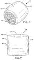
- FIG. 1 illustrates an example of a cold-formed roller blank 10 made in accordance with the present invention.
- the roller blank is of the barrel type, but it will be appreciated that certain principles of the invention are applicable to other roller styles including cylindrical and tapered rollers.
- the roller blank 10 made by the processes and tools disclosed hereinbelow can be produced to dimensional tolerances that are reduced to about 1/10 of that which is presently commercially accepted for subsequent finishing, typically by grinding after heat treatment.
- the roller blank 10 after heat treating and grinding is typically used with multiple identical pieces in anti-friction bearing assemblies as known in the art.
- the roller 10 is formed in a multistation progressive cold-forming machine 11 illustrated in FIG. 3 and of a type generally known in the industry.
- the forging machine 11 is depicted in a plan view of the tooling area in FIG. 3 .
- the machine 11 includes a quill 12 that receives steel wire 13 at a cutoff station 14, the center of which is represented by the center line 16.
- the wire 13, which is of a suitable steel such as AISI 52100, is very precisely fed in increments corresponding to the desired length of an initial workpiece or blank 10a to a shear or cutter 17 by feed apparatus known in the art.
- the machine 11 includes multiple progressive forming stations 21 - 23, preferably three in number.
- the stations 21 - 23 are conventionally uniformly spaced from one another and from the cutoff station 14.
- the forming stations 21 - 23 include die cases 26 - 28 fixed on a stationary die breast or bolster 29 and tool or punch cases 31 - 33 on a slide 34 that reciprocates towards and away from the die breast 29.
- the slide 34 is shown at front dead center in FIG. 3 .
- a conventional transfer mechanism not shown, moves workpieces in steps from the cutoff station 14 to each of the forming stations 21 - 23 in timed relation to cyclical displacement of the slide 34 to and from the die breast 29.
- roller blanks 10 The following description of the formation of roller blanks 10 is made with reference to FIGS. 3 , 4A , B, 5A, B, and 6A, B.
- the initial blank or workpiece 10a of predetermined diameter and precise length is produced by the shear 17 such that each end face 36, 37 of the blank 10a is a sheared surface having irregularities or unevenness inherent in the shearing process.
- the workpiece 10a is transferred to the first forming station 21 represented in FIGS. 4A and 4B .
- Tool and die cavities 41, 42 are formed in respective inserts 43, 44.
- These inserts or tooling elements 43, 44 and others shown in FIGS. 3 and 4 with cross-hatching are formed of carbide or other suitable tooling material.
- a floating die ring 46 including an insert 47.
- the floating die ring 46 is a cup-shaped body with a deep cylindrical skirt 48 and an integral end wall 49.
- the floating die ring skirt 48 is telescoped over the die case 26 with minimal radial clearance between these elements, while allowing axial movement between them.
- the end wall 49 has a central aperture in which the die ring insert 47 is fixed.
- the floating die ring 46 is resiliently biased to a forward position where its end wall 49 and insert 47 is spaced a limited distance from the die cavity 42 and the case 26 (as indicated in the right side of FIGS. 4A and 4B ).
- the biasing force is provided by compression springs 51 (only one is seen in the plane of FIG. 3 ) distributed symmetrically about the axis of the die cavity 42 (corresponding to the center line of the first station 21).
- the forward or extended position of the floating die ring 46 is determined by a tangential pin 52 received in a slot on the periphery of the floating die ring skirt 48.
- FIGS. 4A and 4B a workpiece or initial blank 10a is received in the first station 21.
- the right side of FIGS. 4A and 4B illustrate the beginning of the forming stages on the blank 10a which has been transferred from the cutoff station 14.
- the blank Prior to the instant in the machine cycle depicted at the right side of FIGS. 4A and 4B , the blank has been held in position at this station by its ends 36, 37 with knockout or ejector pins 53, 54, associated with the tool and die elements, respectively.
- These pins 53, 54 are yieldably held in their extended positions from the preceding machine cycle by friction drags, comprising belleville springs 57 and a friction shoe 58 thereby enabling the pins to grip the blank 18 when it is received from the transfer mechanism.
- the tool and die cavities 41, 42 have blank radiused corner forming areas 59 with minimum diameters that in the illustrated example are smaller than the original diameter of the workpiece 10a.
- the left sides of FIGS. 4A and 4B correspond to front dead center of the slide 34 and illustrate completion of the shaping of the workpiece at the first station.
- the workpiece or blank 10b has been partially extruded simultaneously and symmetrically at both of its ends and has been upset at its mid-section.
- the extrusion component of the forming process at this first station 21 results in substantially all of the material forming the original sheared end face 36, 37 to be displaced from the annular radiused corners 59 of the insert cavities 41, 42 which shape the rounded or radiused corners of the blank 10b between the ends of the blank and the sides of the blank. As shown, the radiused corners of the blank are produced by the complimentary-shaped corners 59 of the tool and die cavities 41, 42.
- the floating die ring 46 enables the material of the blank 10b to be fully driven into the corners 59 of the die cavity 42.
- the mid-length section of the blank 10b upsets, it is constrained to a desired size by the floating die ring 46, and specifically the cylindrical interior surface of the insert 47. Friction between the blank 10a and the wall of the floating ring insert 47 cannot significantly restrict displacement of blank material into the die cavity corners 59 because the floating ring 46, by overcoming a relatively small force of the biasing springs 51, can move with the blank stock and with the advancing tool cavity 41 so that substantially the full forging force is transmitted to the blank material in the area of the die cavity corners 59.
- the effect of sidewall friction in the forming cavities of the die side of the tooling is effectively eliminated and the ends of the blank 10b can be formed symmetrically end-to-end essentially simultaneously.
- the second die station 22 represented at FIGS. 5A, 5B , includes a floating die ring 61 similar in construction and function to the die ring 46 of the first station 21 and floating ring insert 60. Associated with the floating die ring 61 are an integral cylindrical skirt 65, springs 51 and a tangential pin 52 serving the same function as described before. Tool and die cavity inserts 62, 63 are mounted in respective cases 32 and 27.
- the first station die ring insert 47 establishes a diameter on the mid-length of the blank 10b (left side of FIGS. 4A and 4B ) that is relatively close, e.g. a slip fit or a clearance fit, to the diameter of the internal cylindrical surface of the floating die ring insert 60 at the second station.
- the blank or workpiece 10b is transferred to the second station 22 and because its diameter is close to the diameter of the inside wall of the insert 60, good alignment is maintained between the blank and tool elements of the second station 22.
- the next blow of the slide 34 causes the blank 10b to upset near its ends to reduce the radius of its corners and to expand its diameter near these corners.
- the floating die ring 61 eliminates the effects of friction between the mid-section of the blank and the die cavity 64 of the floating ring insert 60 so that the blank 10b can be fully upset into the corners 66 of the tool and die cavities 67, 68 of inserts 62, 63 symmetrically, end-for-end and simultaneously.
- FIGS. 6A, 6B symmetrical cavities 81, 82 are formed in tool and die insert sets 83, 84 mounted in the respective tool and die cases 33, 28.
- the right half of FIGS. 6A and 6B shows the start of the forming process and the left half of these figures shows the completed roller blank 10 developed at the end of the cold forming process.
- the blank is formed by a combination of limited extrusion at its ends and upsetting along its mid-length.
- the shaping of the ends from the intermediate blank 10b received from the second station is somewhat limited but quite accurate. Upsetting of the mid-section of the blank 10 produces a final barrel shape.
- the roller blank 10 produced at the third station 23 is very accurately formed for several reasons beyond the initial forming of its rounded corners as described in connection with the forming action at the first and second stations 21, 22.
- radiused corners 88 of the tool and die cavities 81, 82 are not substantially different than those existing at the prior second station 22 so that relatively little shaping is required in these corner areas at this station.
- a guide ring 90 fixed on the die case 28 is very closely fitted to the lead end of the tool case 33 so that when the tool case is received in the ring, both of these tool and die cases are precision aligned with one another.
- the guide ring 90 and lead end of the case 28 are cylindrical.
- the relative lengths of the tool and die cases 33, 28 is made so that there is a slight interference between them in the direction of slide movement when the slide is at front dead center and faces 91, 92 of the die and tool cases are in contact.
- the final shape of the roller blank 10 is accurately and repeatedly determined by the shape of the tooling, i.e. the cavities 81, 82 of the inserts 83, 84.
- the tool insert 83 at least, is recessed slightly from the plane of the tool case 33 so that there is no contact between the tool and die inserts 83, 84 in the front dead center position of the slide.
- the accuracy of the cold-forming machine 10 in making the roller blanks is augmented by the technique of cooling the tooling with lubricant/coolant.
- Lubricant/coolant is circulated with a pump (not shown) through internal passages 94 in the tool and die cases 31 - 33, 26 - 28, and floating die ring skirts 48, 65.
- the coolant can be arranged to keep the temperature of the tools between room temperature and 140° F.
- the method of cooling the tooling elements improves the forming accuracy of the cold-forming machine because it essentially eliminates thermally induced dimensional variations in the tooling which can otherwise result in variations in the dimensional accuracy of the roller blank parts it is making.
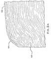
- FIGS. 2 and 2a are photomicrographs of a longitudinally sectioned roller blank made according to the process and with the tooling and machine described hereinabove.
- the roller blank 10 has been etched to highlight its grain structure pattern.
- FIG. 2A is a view similar to FIG. 2 on an enlarged scale showing the grain structure pattern of the roller blank 10 at a radiused corner surface 101 between the peripheral main surface 102 corresponding to the rolling surface and an end surface 103 of the roller 10, the illustrated corner being typical of the other corners.
- the radiused corner surface 101 blends smoothly with the main surface 102.
- the grain pattern is characterized by smooth, uninterrupted lines that are parallel to the main surface 102 that extends along the major length of the roller blank and parallel to the annular radiused corner surfaces 101 at each end of the roller blank.
- the end faces 103 of the roller blank are generally perpendicular to its longitudinal axis which corresponds to the axis of rotation.
- the end faces 103, on the scale of FIGS. 2 and 2A are somewhat irregular since they are the vestiges of the sheared end faces of the original or starting form of the roller blank.
- the roller blank 10 is superior to prior art roller blanks for several reasons.
- the roller blank is manufactured to very precise dimensional tolerances, in some cases in the order of 1/10 of previously expected tolerances, so that it is near the net shape of the finished roller product thereby greatly reducing the amount of machining required to reach specified dimensions and rolling surface finish quality. Since the radiused corners are precisely formed to net shape (i.e. as ultimately used) or near net shape, the machining requirement in these areas is non-existent or minimal.
- the tooling is arranged to exclude the material that forms the original sheared end faces from the radiused corners.
- the absence of this material from such corners is of great advantage because faults and irregularities ordinarily produced in the shearing process cannot exist in the radiused corners.
- Such faults and irregularities in the radiused corners of prior art rollers are known to initiate cracks and premature bearing failure when used in bearing assemblies.
- the disclosed roller blank avoids flash between a plane of separation between the tool and die cavity elements.
- Prior art processes and tooling frequently resulted in a flash ring being created on the periphery of the roller blank where the tool and die elements separate. This ring of flash required extra machining steps and resulted in discontinuous grain patterns at the finished rolling surface.
- Prior art bearing rollers are subject to premature failure adjacent the site of the flash created grain pattern discontinuity.
- roller blank because of its improved grain structure and accurate shape, is capable of reducing costs of anti-friction bearing manufacture and increasing bearing performance in service life.
- a finished anti-friction metal roller 95 for an anti-friction bearing assembly is made by machining the blank 10, ordinarily after heat treatment by grinding a limited amount of material (e.g..07 mm) from its annular main surface 102 and, optionally, from its end surface 103. Suitable grinding equipment and techniques are well known in the industry.
- the axis of rotation of the roller is shown at 96; the ends 99 of the roller are in planes or substantially in planes perpendicular to the axis 96, and a rolling surface 97 is concentrically disposed about the axis 96.
- the grain structure pattern of the roller metal forming the rolling surface 97, and the radiused corner surfaces 98 is parallel to such surfaces, being the result of grinding a small amount of material from the main side 102 of the blank 10.
- one commercial barrel-type roller blank made in accordance with the above description has a nominal major outside diameter of about 18 mm, a nominal length of about 17.5 mm and the radiused corner has a nominal radius of 2.04 mm.
- a barrel-type roller blank has a nominal major diameter of 12 mm, a nominal length of 10 mm and the radiused corners have a nominal radius of 1.4 mm.
- Blanks of these two examples can be ground on the main surface to remote about .07 mm of material, for example, to form the peripheral rolling surface 97 and obtain acceptable commercial size and finish requirements.
- the end faces 99 of the finished roller can typically be left in their cold formed condition without machining, or can be ground as desired.
- the surface of the radiused corners both in the cold formed state and in the finished or ground state of the roller, frequently is not tangent to the peripheral main formed surface or the peripheral finished rolling surface and/or is not tangent to a radial plane at its respective end face.
- a radiused corner surface can intersect the peripheral formed main surface or the peripheral finished rolling surface, and/or a radial end surface at various different angles of, for example, 10, 20 or more degrees.
- An end surface, as originally cold formed can be symmetrically indented around the roller axis and can be ground.
- substantially all of the formed radiused corner surfaces will be devoid of material from the original sheared end face of the starting blank and the grain pattern immediately underlying this radiused corner surface will be parallel to such surface.
- the cold forming of the radiused corner surfaces of a blank to a precise shape and without material from the original irregular sheared end face of a starting blank in accordance with the invention enables the blank to be machined into a finished bearing roller ordinarily without the need to machine the radiused corners.
- tooling and, alternatively, tools includes, separately and collectively, the tool and die inserts, the tool and die cases, and the floating die rings and inserts. In some applications, it may be desirable to integrate the tool cases and the inserts.
Landscapes
- Engineering & Computer Science (AREA)
- Mechanical Engineering (AREA)
- General Engineering & Computer Science (AREA)
- Forging (AREA)
- Rolling Contact Bearings (AREA)
Description
- The invention relates to the manufacture of cold-formed rollers and, in particular, to a process, machine and tooling that affords improvements in roller quality and reduction in manufacturing costs.
- Rollers used in anti-friction bearings are commonly initially made in cold-forming machines. Traditionally, the cold-formed pieces are subsequently machined by grinding processes to achieve a desired precision shape and finish. Typically, grinding operations may involve several steps because the cold-formed part has significant flash and/or excess material as a result of the limitations and characteristics of traditional methods and tooling used in the cold-forming art. Grinding processes are expensive and significantly add to the cost of the finished roller.
-
DD 122 651 A1 -
JP S48 81768 A1 claims 5 and 11 is based. - The invention involves a cold-formed metal roller blank, that is relatively close to the net shape of a finish ground roller thereby greatly reducing machining or grinding costs and that has an improved grain structure which avoids premature bearing failure. The improved cold-formed part results from tooling elements that closely shape a part without flash and with a grain structure that follows the contours of the end edges of the roller and is axially uninterrupted thereby avoiding irregularities in the finished machined product.
- The process involves multistage forming steps and unique tooling capable of producing accurate shapes at each station without the need or risk of flash. The tooling is configured to work a blank that is relatively small in diameter compared to prior art practice, into a part of substantially increased diameter. This technique assures that the material of the sheared end faces of the original blank are essentially excluded from the formed radiused corners between the zone of the rolling surface of the roller and the end faces of the roller.
- The roller blank or workpiece is simultaneously formed at each end, at each station. The annular radiused corners at the ends of the workpiece are progressively accurately formed by filling the corresponding tool and die cavity areas at successive workstations without creating or risking flash at separation planes between the tool and die cavity parts. This flashless forming is accomplished by confining and shaping the mid-length of the blank with a floating die ring that eliminates the effects of friction at the sides of the workpiece which otherwise would inhibit material flow into the cavity corners and promote or require unwanted flash. At the last station, the workpiece is precision formed by closing the tool and die with a positive stop so that the tool geometry determines the final part shape independently of machine variables.
-
-
FIG. 1 is a perspective view of a roller blank made in accordance with the invention; -
FIG. 2 is a photomicrograph of an axial cross-section of the blank ofFIG. 1 , acid etched to illustrate the grain pattern of the roller blank material; -
FIG. 2A is a photomicrograph similar toFIG. 2 of the blank cross-section on an enlarged scale of a typical radiused corner of the blank; -
FIG. 3 is a somewhat schematic plan view of tooling area of a multistation cold-forming or forging machine arranged to perform the process of the invention; -
FIGS 4A and 4B are schematic sectional views of the first station of the machine ofFIG. 3 before and at front dead center of the slide, respectively; -
FIGS. 5A and 5B are schematic sectional views of the second station of the machine ofFIG. 3 before and at front dead center of the slide, respectively; -
FIGS. 6A and 6B are schematic sectional views of the third station of the machine ofFIG. 3 before and at front dead center of the slide, respectively; and -
FIG. 7 is a side view of a finished roller made from the roller blank ofFIGS. 1 and2 . -
FIG. 1 illustrates an example of a cold-formed roller blank 10 made in accordance with the present invention. The roller blank is of the barrel type, but it will be appreciated that certain principles of the invention are applicable to other roller styles including cylindrical and tapered rollers. The roller blank 10 made by the processes and tools disclosed hereinbelow can be produced to dimensional tolerances that are reduced to about 1/10 of that which is presently commercially accepted for subsequent finishing, typically by grinding after heat treatment. The roller blank 10 after heat treating and grinding is typically used with multiple identical pieces in anti-friction bearing assemblies as known in the art. - The
roller 10 is formed in a multistation progressive cold-formingmachine 11 illustrated inFIG. 3 and of a type generally known in the industry. Theforging machine 11 is depicted in a plan view of the tooling area inFIG. 3 . Themachine 11 includes aquill 12 that receivessteel wire 13 at acutoff station 14, the center of which is represented by thecenter line 16. Thewire 13, which is of a suitable steel such as AISI 52100, is very precisely fed in increments corresponding to the desired length of an initial workpiece or blank 10a to a shear orcutter 17 by feed apparatus known in the art. Themachine 11 includes multiple progressive forming stations 21 - 23, preferably three in number. The stations 21 - 23 are conventionally uniformly spaced from one another and from thecutoff station 14. The forming stations 21 - 23 include die cases 26 - 28 fixed on a stationary die breast orbolster 29 and tool or punch cases 31 - 33 on aslide 34 that reciprocates towards and away from the diebreast 29. Theslide 34 is shown at front dead center inFIG. 3 . A conventional transfer mechanism, not shown, moves workpieces in steps from thecutoff station 14 to each of the forming stations 21 - 23 in timed relation to cyclical displacement of theslide 34 to and from thedie breast 29. - The following description of the formation of
roller blanks 10 is made with reference toFIGS. 3 ,4A , B, 5A, B, and 6A, B. The initial blank orworkpiece 10a of predetermined diameter and precise length is produced by theshear 17 such that eachend face workpiece 10a is transferred to the first formingstation 21 represented inFIGS. 4A and 4B . Tool and diecavities respective inserts tooling elements FIGS. 3 and4 with cross-hatching are formed of carbide or other suitable tooling material. Associated with thedie cavity 42 is afloating die ring 46 including aninsert 47. Thesecavities ring 46, and insert 47, as well as others to be described, are annular or ring-like in form. As shown inFIG. 3 , the floatingdie ring 46 is a cup-shaped body with a deepcylindrical skirt 48 and anintegral end wall 49. As indicated inFIG. 3 , the floatingdie ring skirt 48 is telescoped over thedie case 26 with minimal radial clearance between these elements, while allowing axial movement between them. Theend wall 49 has a central aperture in which the diering insert 47 is fixed. - The floating
die ring 46 is resiliently biased to a forward position where itsend wall 49 andinsert 47 is spaced a limited distance from thedie cavity 42 and the case 26 (as indicated in the right side ofFIGS. 4A and 4B ). The biasing force is provided by compression springs 51 (only one is seen in the plane ofFIG. 3 ) distributed symmetrically about the axis of the die cavity 42 (corresponding to the center line of the first station 21). The forward or extended position of the floatingdie ring 46 is determined by atangential pin 52 received in a slot on the periphery of the floatingdie ring skirt 48. - Referring to
FIGS. 4A and 4B , a workpiece or initial blank 10a is received in thefirst station 21. The right side ofFIGS. 4A and 4B illustrate the beginning of the forming stages on the blank 10a which has been transferred from thecutoff station 14. Prior to the instant in the machine cycle depicted at the right side ofFIGS. 4A and 4B , the blank has been held in position at this station by itsends pins friction shoe 58 thereby enabling the pins to grip the blank 18 when it is received from the transfer mechanism. Similar friction drags on the knockout pins at thesubsequent stations cavities corner forming areas 59 with minimum diameters that in the illustrated example are smaller than the original diameter of theworkpiece 10a. The left sides ofFIGS. 4A and 4B correspond to front dead center of theslide 34 and illustrate completion of the shaping of the workpiece at the first station. In the illustrated process, the workpiece or blank 10b has been partially extruded simultaneously and symmetrically at both of its ends and has been upset at its mid-section. The extrusion component of the forming process at thisfirst station 21 results in substantially all of the material forming the originalsheared end face radiused corners 59 of theinsert cavities corners 59 of the tool and diecavities - The floating
die ring 46 enables the material of the blank 10b to be fully driven into thecorners 59 of thedie cavity 42. When the mid-length section of the blank 10b upsets, it is constrained to a desired size by the floatingdie ring 46, and specifically the cylindrical interior surface of theinsert 47. Friction between the blank 10a and the wall of the floatingring insert 47 cannot significantly restrict displacement of blank material into thedie cavity corners 59 because the floatingring 46, by overcoming a relatively small force of the biasing springs 51, can move with the blank stock and with the advancingtool cavity 41 so that substantially the full forging force is transmitted to the blank material in the area of thedie cavity corners 59. Thus, the effect of sidewall friction in the forming cavities of the die side of the tooling is effectively eliminated and the ends of the blank 10b can be formed symmetrically end-to-end essentially simultaneously. - The
second die station 22, represented atFIGS. 5A, 5B , includes a floatingdie ring 61 similar in construction and function to thedie ring 46 of thefirst station 21 and floatingring insert 60. Associated with the floatingdie ring 61 are an integralcylindrical skirt 65, springs 51 and atangential pin 52 serving the same function as described before. Tool and die cavity inserts 62, 63 are mounted inrespective cases - The first station die
ring insert 47 establishes a diameter on the mid-length of the blank 10b (left side ofFIGS. 4A and 4B ) that is relatively close, e.g. a slip fit or a clearance fit, to the diameter of the internal cylindrical surface of the floatingdie ring insert 60 at the second station. The blank orworkpiece 10b is transferred to thesecond station 22 and because its diameter is close to the diameter of the inside wall of theinsert 60, good alignment is maintained between the blank and tool elements of thesecond station 22. At this station, the next blow of theslide 34 causes the blank 10b to upset near its ends to reduce the radius of its corners and to expand its diameter near these corners. The floatingdie ring 61, as in thefirst station 21, eliminates the effects of friction between the mid-section of the blank and thedie cavity 64 of the floatingring insert 60 so that the blank 10b can be fully upset into thecorners 66 of the tool and diecavities inserts - At the
third station 23, seen inFIGS. 6A, 6B ,symmetrical cavities cases FIGS. 6A and 6B shows the start of the forming process and the left half of these figures shows the completed roller blank 10 developed at the end of the cold forming process. At thisstation 23, as can be seen in a comparison of the right and left halves ofFIGS. 6A and 6B , the blank is formed by a combination of limited extrusion at its ends and upsetting along its mid-length. The shaping of the ends from the intermediate blank 10b received from the second station is somewhat limited but quite accurate. Upsetting of the mid-section of the blank 10 produces a final barrel shape. - The roller blank 10 produced at the
third station 23 is very accurately formed for several reasons beyond the initial forming of its rounded corners as described in connection with the forming action at the first andsecond stations corners 88 of the tool and diecavities second station 22 so that relatively little shaping is required in these corner areas at this station. Secondly, aguide ring 90 fixed on thedie case 28 is very closely fitted to the lead end of thetool case 33 so that when the tool case is received in the ring, both of these tool and die cases are precision aligned with one another. Theguide ring 90 and lead end of thecase 28 are cylindrical. - The relative lengths of the tool and die
cases cavities inserts tool insert 83, at least, is recessed slightly from the plane of thetool case 33 so that there is no contact between the tool and dieinserts - The accuracy of the cold-forming
machine 10 in making the roller blanks is augmented by the technique of cooling the tooling with lubricant/coolant. Lubricant/coolant is circulated with a pump (not shown) throughinternal passages 94 in the tool and die cases 31 - 33, 26 - 28, and floatingdie ring skirts - Comparing the configuration of the original blank 10a with the
finished shape 10, it will be seen that the disclosed process departs from conventional practice in that a relatively large percentage of upset, i.e. change in diameter, is performed on the blank. This technique is helpful in removing irregularities out of the rounded or radiused corners of the blank 10. -
FIGS. 2 and2a are photomicrographs of a longitudinally sectioned roller blank made according to the process and with the tooling and machine described hereinabove. The roller blank 10 has been etched to highlight its grain structure pattern.FIG. 2A is a view similar toFIG. 2 on an enlarged scale showing the grain structure pattern of the roller blank 10 at aradiused corner surface 101 between the peripheralmain surface 102 corresponding to the rolling surface and anend surface 103 of theroller 10, the illustrated corner being typical of the other corners. In the illustrated example of the roller blank 10 particularly shown inFIG. 2A , theradiused corner surface 101 blends smoothly with themain surface 102. The grain pattern is characterized by smooth, uninterrupted lines that are parallel to themain surface 102 that extends along the major length of the roller blank and parallel to the annular radiused corner surfaces 101 at each end of the roller blank. The end faces 103 of the roller blank are generally perpendicular to its longitudinal axis which corresponds to the axis of rotation. The end faces 103, on the scale ofFIGS. 2 and2A are somewhat irregular since they are the vestiges of the sheared end faces of the original or starting form of the roller blank. - The roller blank 10 is superior to prior art roller blanks for several reasons. The roller blank is manufactured to very precise dimensional tolerances, in some cases in the order of 1/10 of previously expected tolerances, so that it is near the net shape of the finished roller product thereby greatly reducing the amount of machining required to reach specified dimensions and rolling surface finish quality. Since the radiused corners are precisely formed to net shape (i.e. as ultimately used) or near net shape, the machining requirement in these areas is non-existent or minimal.
- In the disclosed process, the tooling is arranged to exclude the material that forms the original sheared end faces from the radiused corners. The absence of this material from such corners is of great advantage because faults and irregularities ordinarily produced in the shearing process cannot exist in the radiused corners. Such faults and irregularities in the radiused corners of prior art rollers are known to initiate cracks and premature bearing failure when used in bearing assemblies. Still further, the disclosed roller blank avoids flash between a plane of separation between the tool and die cavity elements. Prior art processes and tooling frequently resulted in a flash ring being created on the periphery of the roller blank where the tool and die elements separate. This ring of flash required extra machining steps and resulted in discontinuous grain patterns at the finished rolling surface. Prior art bearing rollers are subject to premature failure adjacent the site of the flash created grain pattern discontinuity.
- From the foregoing, it will be understood that the roller blank, because of its improved grain structure and accurate shape, is capable of reducing costs of anti-friction bearing manufacture and increasing bearing performance in service life.
- A finished
anti-friction metal roller 95 for an anti-friction bearing assembly, shown inFIG. 7 , is made by machining the blank 10, ordinarily after heat treatment by grinding a limited amount of material (e.g..07 mm) from its annularmain surface 102 and, optionally, from itsend surface 103. Suitable grinding equipment and techniques are well known in the industry. The axis of rotation of the roller is shown at 96; theends 99 of the roller are in planes or substantially in planes perpendicular to theaxis 96, and a rollingsurface 97 is concentrically disposed about theaxis 96. The grain structure pattern of the roller metal forming the rollingsurface 97, and the radiused corner surfaces 98 is parallel to such surfaces, being the result of grinding a small amount of material from themain side 102 of the blank 10. By way of example, one commercial barrel-type roller blank made in accordance with the above description has a nominal major outside diameter of about 18 mm, a nominal length of about 17.5 mm and the radiused corner has a nominal radius of 2.04 mm. In another commercial example, a barrel-type roller blank has a nominal major diameter of 12 mm, a nominal length of 10 mm and the radiused corners have a nominal radius of 1.4 mm. Blanks of these two examples can be ground on the main surface to remote about .07 mm of material, for example, to form the peripheral rollingsurface 97 and obtain acceptable commercial size and finish requirements. The end faces 99 of the finished roller can typically be left in their cold formed condition without machining, or can be ground as desired. - In various roller designs, the surface of the radiused corners, both in the cold formed state and in the finished or ground state of the roller, frequently is not tangent to the peripheral main formed surface or the peripheral finished rolling surface and/or is not tangent to a radial plane at its respective end face. For example, a radiused corner surface can intersect the peripheral formed main surface or the peripheral finished rolling surface, and/or a radial end surface at various different angles of, for example, 10, 20 or more degrees. An end surface, as originally cold formed, can be symmetrically indented around the roller axis and can be ground.
- Ideally, when practicing the invention substantially all of the formed radiused corner surfaces will be devoid of material from the original sheared end face of the starting blank and the grain pattern immediately underlying this radiused corner surface will be parallel to such surface. The cold forming of the radiused corner surfaces of a blank to a precise shape and without material from the original irregular sheared end face of a starting blank in accordance with the invention enables the blank to be machined into a finished bearing roller ordinarily without the need to machine the radiused corners.
- It should be evident that this disclosure is by way of example and that various changes may be made by adding, modifying or eliminating details without departing from the scope of the appended claims. As used herein, the term tooling and, alternatively, tools includes, separately and collectively, the tool and die inserts, the tool and die cases, and the floating die rings and inserts. In some applications, it may be desirable to integrate the tool cases and the inserts.
Claims (19)
- A cold-formed metal bearing roller (95) made from sheared end cylindrical blank (10) having a continuous annular main surface (102) corresponding to a rolling surface concentric about a central axis (96) of rotation and disposed between a pair of end faces (103) generally perpendicular to said central axis, the end faces (103) generally representing the ends of the roller, an annular radiused corner surface (98) at each end of the roller extending smoothly from the main surface, the radiused corner at each end of the roller forming a transition area between the main surface and a respective end face, characterized in that the material forming each of said radiused corner surfaces (101) and the material immediately adjacent said main surface (102) have a grain pattern that is substantially parallel in an axial plane to said radiused corner surfaces (101) and said main surface (102).
- A metal bearing roller as set forth in claim 1, wherein each end face (103) is formed of the material that existed at the sheared end of a blank (10) from which the roller (95) was formed.
- A metal bearing roller produced from a cold-formed blank as set forth in claim 1, by grinding the main surface (102) to its finished condition.
- A metal bearing roller as set forth in claim 1, wherein the main surface (102) is in a cold-formed condition.
- A method of cold-forming near net shape metal roller blanks (10) for anti-friction bearings comprising shearing a blank from wire (13) of a predetermined size to a predetermined length, transferring the blank to a plurality of successive workstations (21-23), forming the blank at the workstations to create a main annular surface (102) surrounding a latent rolling surface which can be machined away to produce said rolling surface, opposed roller end faces (103), and annular radiused corners (101) at the ends of the main surface forming uniform transitions from the main surface (102) to the end faces (103), characterized in that the formation of the blank is performed in a manner such that the material forming the original sheared wire end faces is substantially fully excluded from the surface of the radiused corners (101) , wherein the blank is simultaneously and symmetrically extruded at both of its ends and upset at its mid section to exclude the sheared wire end faces from the surface of the radiused corners (101).
- A method as set forth in claim 5, wherein the blank is upset between a tool cavity (41) and a die cavity (42), the blank being constrained by a floating die element capable of moving in the slide direction with the blank material while the blank is driven into the die cavity to shape the radiused corners of the blank so as to reduce the effects of friction between the blank and floating die element in the formation of the corners of the blank in the die cavity.
- A method as set forth in claim 6, wherein the blank is transferred from a workstation (21) where the diameter of its mid-section is formed by the floating die element (47) to a subsequent workstation (22) having another floating die element (40) associated with another die cavity.
- A method as set forth in claim 7, wherein the floating die elements are rings and the floating ring (47) at the first mentioned workstation is sized to form the blank with a diameter at its mid-section that is a slip fit with the floating ring (60) at the second mentioned workstation.
- A method as set forth in claim 5, wherein said blank at a final workstation (23) is formed by tool and die cavities (81, 82) carried in respective cases (33, 28), said cases being arranged to limit movement of the final workstation tool and die cavities at the front dead center of a slide carrying said tool cavities.
- A method as set forth in claim 5, wherein the tools are maintained in a limited operating temperature range by circulation of coolant liquid through tool cases on a die breast (29) and reciprocating slide (34).
- A set of tooling for cold-forming metal roller blanks comprising a pair of tool and die cavities (41, 42) for simultaneously forming the ends of a blank with radiused corners characterized in that floating die ring (47) is provided for shaping the blank by circumferentially constraining its mid-section while being driven towards the die cavity by friction between the floating die ring and the blank independently of direct correspondence with movement of the tool cavity such that friction between the mid-section of the blank is effectively eliminated as a retarding force which would otherwise operate to diminish the filling of the radiused corners (59) of the die cavity with the blank material.
- A set of tooling as set forth in claim 11, wherein the die cavity is in a case (26) and said floating die ring is arranged to be supported by said case for movement towards said die cavity.
- A set of tooling as set forth in claim 12, wherein said case has a cylindrical portion with its axis aligned with the direction of slide movement and said floating die ring (60) has a skirt (48) telescoped over the cylindrical portion of said case.
- A set of tooling as set forth in claim 13, wherein said die cavity is an insert carried in said case.
- A set of tooling as set forth in claim 11, including a second pair of tool and die cavities (47, 48) and a floating die ring for said second die cavity, said second pair of tool and die cavities being arranged to shape the ends of a blank received from said first tool and die cavities and the first floating die ring.
- A set of tooling as set forth in claim 15, wherein said first floating die ring is sized to form the mid-section of the blank to produce a slip fit in the second floating die ring.
- A set of tooling as set forth in claim 15, including a third pair of tool and die cavities (81, 82) configured to finish shape a blank received from the second pair of tool and die cavities.
- A set of tooling as set forth in claim 17, including a guide (90), separate from said slide, to closely align said third pair of cavities.
- A set of tooling as set forth in claim 17, wherein said pairs of tool and die cavities have associated passages (94) for circulating coolant to maintain said tool cavities at a predetermined temperature range.
Applications Claiming Priority (2)
| Application Number | Priority Date | Filing Date | Title |
|---|---|---|---|
| US10/890,339 US7377042B2 (en) | 2004-07-13 | 2004-07-13 | Method of cold-forming near net shape metal roller blanks for anti-friction bearings |
| PCT/US2005/024637 WO2006017260A2 (en) | 2004-07-13 | 2005-07-12 | Forged roller |
Publications (3)
| Publication Number | Publication Date |
|---|---|
| EP1882108A2 EP1882108A2 (en) | 2008-01-30 |
| EP1882108A4 EP1882108A4 (en) | 2014-01-01 |
| EP1882108B1 true EP1882108B1 (en) | 2016-10-12 |
Family
ID=35599511
Family Applications (1)
| Application Number | Title | Priority Date | Filing Date |
|---|---|---|---|
| EP05770490.0A Expired - Lifetime EP1882108B1 (en) | 2004-07-13 | 2005-07-12 | Forged roller |
Country Status (5)
| Country | Link |
|---|---|
| US (3) | US7377042B2 (en) |
| EP (1) | EP1882108B1 (en) |
| JP (2) | JP4942650B2 (en) |
| CN (1) | CN101410641B (en) |
| WO (1) | WO2006017260A2 (en) |
Families Citing this family (28)
| Publication number | Priority date | Publication date | Assignee | Title |
|---|---|---|---|---|
| US7377042B2 (en) * | 2004-07-13 | 2008-05-27 | National Machinery Llc | Method of cold-forming near net shape metal roller blanks for anti-friction bearings |
| JP4377901B2 (en) * | 2006-10-05 | 2009-12-02 | 株式会社ゴーシュー | Method and apparatus for manufacturing high-strength processed material |
| EP2239069B1 (en) * | 2008-01-29 | 2016-11-23 | NSK Ltd. | Method for manufacturing outward-flanged metallic member |
| US20100071649A1 (en) | 2008-09-23 | 2010-03-25 | Eaton Corporation | Ball plunger for use in a hydraulic lash adjuster and method of making same |
| CN102554033B (en) * | 2012-01-17 | 2016-05-11 | 洛阳市人诚轴承配件有限责任公司 | A kind of stamping die for roller cold heading machine |
| US9120138B2 (en) * | 2012-10-10 | 2015-09-01 | National Machinery Llc | Forged sideways extrusion |
| CN103008460B (en) * | 2012-12-10 | 2015-06-17 | 柳州市金元机械制造有限公司 | Manufacturing method of automobile engine mounting bracket and die for manufacturing automobile engine mounting bracket |
| CN103008475B (en) * | 2012-12-26 | 2015-06-24 | 宁波刚发实业有限公司 | Stainless steel washer progressive die |
| US9120143B2 (en) * | 2013-01-15 | 2015-09-01 | National Machinery Llc | Cut-off end surface improvement |
| CN103273538B (en) * | 2013-06-07 | 2015-09-23 | 南通超达机械科技有限公司 | The die cutting die of floating modular belt positioning inhibiting device |
| EP2944800B1 (en) * | 2014-05-13 | 2022-08-24 | Aktiebolaget SKF | Method for manufacturing a roller, adapted to equip a mechanical system forming a cam follower. |
| CN104097032B (en) * | 2014-06-26 | 2016-05-11 | 庹汉彪 | A kind of bearing needle moulding process |
| CN104084510B (en) * | 2014-06-30 | 2015-12-09 | 江苏力星通用钢球股份有限公司 | A kind of taper roller four station precise forming system |
| DE102014018669A1 (en) * | 2014-12-18 | 2016-06-23 | Kid-Systeme Gmbh | Power supply for seat-related power supply of an electrical unit, in particular in an aircraft, and method for wireless readout of status information of a power supply. |
| US9545659B2 (en) * | 2015-02-19 | 2017-01-17 | National Machinery Llc | Poppet pin ejector |
| CN104759534B (en) * | 2015-03-24 | 2016-11-30 | 安徽汇精模具研发科技有限公司 | Riveting multistation progressive die in front, contact in mould |
| CN105312465A (en) * | 2015-11-25 | 2016-02-10 | 江苏力星通用钢球股份有限公司 | Four-station roller forming process of cold header |
| CN105945140B (en) * | 2016-06-14 | 2017-08-25 | 安徽晶赛科技股份有限公司 | A kind of floating type strip drawing progressive die |
| CN106216531A (en) * | 2016-08-03 | 2016-12-14 | 安徽汇精模具研发科技有限公司 | Silver contact front riveting die set on a kind of switch on wall metalwork |
| EP3628413B1 (en) * | 2017-07-28 | 2021-11-24 | NSK Ltd. | Molding device for manufacturing cylindrical rolling body, manufacturing method for cylindrical rolling body, manufacturing method for rolling bearing, manufacturing method for vehicle, and manufacturing method for mechanical apparatus |
| CN108381187B (en) * | 2018-04-26 | 2023-12-26 | 海盐力度紧固件有限公司 | Screw heading machine with shearing function |
| CN108465734B (en) * | 2018-05-04 | 2024-04-12 | 东光县飞天冷弯机械制造有限公司 | Corner protection net forming machine |
| CN109226649A (en) * | 2018-10-17 | 2019-01-18 | 济南大学 | A kind of steel ball cold heading experimental rig |
| CN109926532B (en) * | 2019-03-20 | 2021-04-02 | 江苏森威精锻有限公司 | Multi-station precision forming process for hub bearing outer ring and implementation device thereof |
| CN110091138A (en) * | 2019-06-18 | 2019-08-06 | 常熟希那基汽车零件有限公司 | A kind of novel hollow production method of shaft |
| CN111531115B (en) * | 2020-03-31 | 2021-07-23 | 江苏恩诺轴研科技有限公司 | Cold forging production process for bearing roller |
| CN116393633A (en) * | 2023-03-31 | 2023-07-07 | 四川丰元机械制造有限公司 | A kind of forging method of roll end flat head forging for rolling mill |
| CN118595332B (en) * | 2024-06-14 | 2026-03-10 | 湖南星途航空航天器制造有限公司 | Fine blanking method and die for thick material narrow edge ring type parts |
Citations (1)
| Publication number | Priority date | Publication date | Assignee | Title |
|---|---|---|---|---|
| US1601252A (en) * | 1924-12-20 | 1926-09-28 | Lines Charles Henry | Method of rounding the edges at the ends of cylindrical rollers for roller bearings |
Family Cites Families (38)
| Publication number | Priority date | Publication date | Assignee | Title |
|---|---|---|---|---|
| DE122651C (en) | ||||
| US585821A (en) * | 1897-07-06 | Island | ||
| US1205796A (en) * | 1913-02-26 | 1916-11-21 | Jakob Schlumpf | Device for pressing rollers, particularly for lacing-eyelets. |
| US1640964A (en) * | 1923-10-26 | 1927-08-30 | Timken Roller Bearing Co | Roll-making machine |
| US1957922A (en) * | 1932-05-24 | 1934-05-08 | Waterbury Farrel Foundry Co | Method of making nuts and like articles |
| US2603987A (en) * | 1942-01-12 | 1952-07-22 | Lyon George Albert | Apparatus for making cartridge casing blanks or the like |
| JPS5029439B1 (en) * | 1970-12-28 | 1975-09-23 | ||
| JPS5147659B1 (en) * | 1971-06-14 | 1976-12-16 | ||
| US3791188A (en) * | 1971-10-26 | 1974-02-12 | E Deussen | Method of die-forming parts with improved grain structure |
| JPS5225391B2 (en) * | 1972-02-02 | 1977-07-07 | ||
| US3842646A (en) * | 1973-04-20 | 1974-10-22 | Gleason Works | Process and apparatus for densifying powder metal compact to form a gear having a hub portion,and preferred powder metal compact shape for use therewith |
| JPS50117137A (en) * | 1974-03-01 | 1975-09-12 | ||
| JPS50117137U (en) * | 1974-03-13 | 1975-09-25 | ||
| DD122651A1 (en) * | 1975-10-15 | 1976-10-20 | ||
| JPS54118437A (en) * | 1978-03-07 | 1979-09-13 | Akiyoshi Matsushige | Refractory heat insulating coating material |
| DE2927135B1 (en) * | 1979-07-05 | 1980-09-11 | Kabel Metallwerke Ghh | Method and device for producing bevel gears |
| JPS5992142A (en) * | 1982-11-17 | 1984-05-28 | Takehiko Kondo | Forming and forging method of nut |
| DE3343623A1 (en) * | 1983-12-02 | 1985-06-13 | Thyssen Industrie AG Schmiedetechnik/Bergbautechnik, 4100 Duisburg | FORGING PRESS AND CONTROL FOR THIS |
| JPS63145534A (en) * | 1986-12-08 | 1988-06-17 | Mitsubishi Electric Corp | Data processor |
| JPS63145534U (en) * | 1987-03-17 | 1988-09-26 | ||
| JPS63278629A (en) * | 1987-05-11 | 1988-11-16 | Sakamura Kikai Seisakusho:Kk | Method and device for pressing circular columnar product having spherical face at both ends |
| JP2511141Y2 (en) * | 1993-01-14 | 1996-09-18 | 株式会社阪村機械製作所 | Hot forging equipment |
| GB9311215D0 (en) * | 1993-05-29 | 1993-07-14 | Metal Box Plc | Spacer |
| JP3554005B2 (en) * | 1993-12-24 | 2004-08-11 | 本田技研工業株式会社 | Forging die |
| JPH07241644A (en) * | 1994-03-04 | 1995-09-19 | Toyota Motor Corp | Extruder |
| JPH0910883A (en) * | 1995-06-30 | 1997-01-14 | Hitachi Ltd | Gear molding method |
| JP3648801B2 (en) * | 1995-09-14 | 2005-05-18 | 日本精工株式会社 | Roller bearing roller manufacturing method |
| JP3341981B2 (en) * | 1997-08-27 | 2002-11-05 | 本田技研工業株式会社 | Helical gear sizing device and sizing method |
| SE512119C2 (en) * | 1998-06-29 | 2000-01-31 | Eric Wirgarth | Press tool for submersible forging and procedure for submersible forging with this tool |
| JP4159063B2 (en) * | 1998-12-25 | 2008-10-01 | アイシン機工株式会社 | Forging equipment |
| JP3949319B2 (en) * | 1999-07-14 | 2007-07-25 | 株式会社ジェイテクト | Roller bearing and manufacturing method thereof |
| US6440237B1 (en) * | 2000-05-23 | 2002-08-27 | Delphi Technologies, Inc. | Process for forming cold formed high-load bearing steel parts |
| JP2002307126A (en) * | 2001-04-10 | 2002-10-22 | Komatsu Sanki Kk | Tooth profile molding method |
| JP2002332960A (en) * | 2001-05-10 | 2002-11-22 | Toyota Industries Corp | Method of manufacturing shoe |
| JP3600813B2 (en) * | 2001-10-30 | 2004-12-15 | Gmb株式会社 | Needle roller compression device and needle roller compression method |
| JP2003181590A (en) * | 2001-12-13 | 2003-07-02 | Daido Steel Co Ltd | Ball-shaped product, its manufacturing method and its manufacturing apparatus |
| JP4053405B2 (en) * | 2002-11-05 | 2008-02-27 | トヨタ自動車株式会社 | Mold for molding external tooth parts and molding method |
| US7377042B2 (en) * | 2004-07-13 | 2008-05-27 | National Machinery Llc | Method of cold-forming near net shape metal roller blanks for anti-friction bearings |
-
2004
- 2004-07-13 US US10/890,339 patent/US7377042B2/en active Active
-
2005
- 2005-07-12 EP EP05770490.0A patent/EP1882108B1/en not_active Expired - Lifetime
- 2005-07-12 CN CN2005800294080A patent/CN101410641B/en not_active Expired - Lifetime
- 2005-07-12 WO PCT/US2005/024637 patent/WO2006017260A2/en not_active Ceased
- 2005-07-12 JP JP2007521555A patent/JP4942650B2/en not_active Expired - Fee Related
-
2008
- 2008-05-20 US US12/123,485 patent/US7712221B2/en not_active Expired - Lifetime
- 2008-05-20 US US12/123,488 patent/US7634934B2/en not_active Expired - Lifetime
-
2011
- 2011-08-17 JP JP2011178464A patent/JP5504222B2/en not_active Expired - Fee Related
Patent Citations (1)
| Publication number | Priority date | Publication date | Assignee | Title |
|---|---|---|---|---|
| US1601252A (en) * | 1924-12-20 | 1926-09-28 | Lines Charles Henry | Method of rounding the edges at the ends of cylindrical rollers for roller bearings |
Also Published As
| Publication number | Publication date |
|---|---|
| US7377042B2 (en) | 2008-05-27 |
| CN101410641B (en) | 2012-07-04 |
| WO2006017260A2 (en) | 2006-02-16 |
| JP5504222B2 (en) | 2014-05-28 |
| US7712221B2 (en) | 2010-05-11 |
| CN101410641A (en) | 2009-04-15 |
| BRPI0513177A (en) | 2008-04-29 |
| JP2012006082A (en) | 2012-01-12 |
| US7634934B2 (en) | 2009-12-22 |
| US20080216550A1 (en) | 2008-09-11 |
| EP1882108A4 (en) | 2014-01-01 |
| US20080216319A1 (en) | 2008-09-11 |
| JP2008506903A (en) | 2008-03-06 |
| WO2006017260A3 (en) | 2008-10-23 |
| EP1882108A2 (en) | 2008-01-30 |
| JP4942650B2 (en) | 2012-05-30 |
| US20060013521A1 (en) | 2006-01-19 |
Similar Documents
| Publication | Publication Date | Title |
|---|---|---|
| US7712221B2 (en) | Method of cold-forming near net shape metal roller blanks for anti-friction bearings | |
| US9016184B2 (en) | Precision forged cartridge case | |
| EP2000688B1 (en) | Method for producing a forged inner ring for constant velocity universal joint and manufacturing apparatus therefor | |
| EP3372324B1 (en) | Long cartridge case | |
| CN114309442B (en) | Milling-free machining method for ball channel of inner star wheel of automobile universal joint | |
| US3434322A (en) | Method and apparatus for rolling bearing races | |
| US7588834B2 (en) | Trimless forged products and method | |
| JP2023058507A (en) | Bearing element, bearing, machine and vehicle | |
| CN101091070A (en) | Apparatus and method for manufacturing outer ring member for constant velocity joint and intermediate molded body of the outer ring member | |
| US3288542A (en) | Method of rolling bearing races | |
| CN113941678B (en) | Forging process for hub sleeve warm forging and cold extrusion and die thereof | |
| US7347077B2 (en) | Method of manufacturing outer ring member for constant velocity joint | |
| EP2566655B1 (en) | Piston assembly multiple step forming process | |
| US20080120846A1 (en) | Apparatus And Method For Manufacturing Outer Race Member For Constant Velocity Joint And Intermediate Molded Body Of The Outer Race Member | |
| HK1223065A1 (en) | Poppet pin ejector | |
| JP7753231B2 (en) | Apparatus and method for manufacturing blanks for rings or tubular members | |
| JP6096051B2 (en) | Manufacturing method of outer joint member for constant velocity universal joint, intermediate forged product and final forged product processed into outer joint member | |
| Bhupatiraju et al. | Cold extrusion | |
| JPH02133136A (en) | Manufacture of warm or hot forged parts | |
| BRPI0513177B1 (en) | METAL BEARING, FORGED METAL BEARING, COLD FORMING METHOD, TOOL SET AND MACHINE |
Legal Events
| Date | Code | Title | Description |
|---|---|---|---|
| PUAI | Public reference made under article 153(3) epc to a published international application that has entered the european phase |
Free format text: ORIGINAL CODE: 0009012 |
|
| AK | Designated contracting states |
Kind code of ref document: A2 Designated state(s): DE FR IT PL SE |
|
| R17D | Deferred search report published (corrected) |
Effective date: 20081023 |
|
| RIC1 | Information provided on ipc code assigned before grant |
Ipc: B21H 1/14 20060101ALI20081117BHEP Ipc: F16C 33/34 20060101AFI20081117BHEP |
|
| 17P | Request for examination filed |
Effective date: 20070108 |
|
| RBV | Designated contracting states (corrected) |
Designated state(s): DE FR IT PL SE |
|
| A4 | Supplementary search report drawn up and despatched |
Effective date: 20131204 |
|
| RIC1 | Information provided on ipc code assigned before grant |
Ipc: F16C 33/34 20060101AFI20131128BHEP Ipc: B21K 1/02 20060101ALI20131128BHEP Ipc: B21J 9/02 20060101ALI20131128BHEP |
|
| 17Q | First examination report despatched |
Effective date: 20150203 |
|
| GRAP | Despatch of communication of intention to grant a patent |
Free format text: ORIGINAL CODE: EPIDOSNIGR1 |
|
| INTG | Intention to grant announced |
Effective date: 20160527 |
|
| GRAS | Grant fee paid |
Free format text: ORIGINAL CODE: EPIDOSNIGR3 |
|
| GRAA | (expected) grant |
Free format text: ORIGINAL CODE: 0009210 |
|
| AK | Designated contracting states |
Kind code of ref document: B1 Designated state(s): DE FR IT PL SE |
|
| REG | Reference to a national code |
Ref country code: DE Ref legal event code: R096 Ref document number: 602005050434 Country of ref document: DE |
|
| PG25 | Lapsed in a contracting state [announced via postgrant information from national office to epo] |
Ref country code: SE Free format text: LAPSE BECAUSE OF FAILURE TO SUBMIT A TRANSLATION OF THE DESCRIPTION OR TO PAY THE FEE WITHIN THE PRESCRIBED TIME-LIMIT Effective date: 20161012 |
|
| PG25 | Lapsed in a contracting state [announced via postgrant information from national office to epo] |
Ref country code: PL Free format text: LAPSE BECAUSE OF FAILURE TO SUBMIT A TRANSLATION OF THE DESCRIPTION OR TO PAY THE FEE WITHIN THE PRESCRIBED TIME-LIMIT Effective date: 20161012 |
|
| REG | Reference to a national code |
Ref country code: DE Ref legal event code: R097 Ref document number: 602005050434 Country of ref document: DE |
|
| PLBE | No opposition filed within time limit |
Free format text: ORIGINAL CODE: 0009261 |
|
| STAA | Information on the status of an ep patent application or granted ep patent |
Free format text: STATUS: NO OPPOSITION FILED WITHIN TIME LIMIT |
|
| 26N | No opposition filed |
Effective date: 20170713 |
|
| REG | Reference to a national code |
Ref country code: FR Ref legal event code: ST Effective date: 20180330 |
|
| PG25 | Lapsed in a contracting state [announced via postgrant information from national office to epo] |
Ref country code: FR Free format text: LAPSE BECAUSE OF NON-PAYMENT OF DUE FEES Effective date: 20170731 |
|
| PGFP | Annual fee paid to national office [announced via postgrant information from national office to epo] |
Ref country code: DE Payment date: 20240705 Year of fee payment: 20 |
|
| PGFP | Annual fee paid to national office [announced via postgrant information from national office to epo] |
Ref country code: IT Payment date: 20240726 Year of fee payment: 20 |
|
| REG | Reference to a national code |
Ref country code: DE Ref legal event code: R071 Ref document number: 602005050434 Country of ref document: DE |