EP1880942B1 - Closure and docking arrangement for a flexible bag, process for emptying and/or filling bulk material from flexible bags and two coupled flexible bags - Google Patents
Closure and docking arrangement for a flexible bag, process for emptying and/or filling bulk material from flexible bags and two coupled flexible bags Download PDFInfo
- Publication number
- EP1880942B1 EP1880942B1 EP06014378A EP06014378A EP1880942B1 EP 1880942 B1 EP1880942 B1 EP 1880942B1 EP 06014378 A EP06014378 A EP 06014378A EP 06014378 A EP06014378 A EP 06014378A EP 1880942 B1 EP1880942 B1 EP 1880942B1
- Authority
- EP
- European Patent Office
- Prior art keywords
- seal
- coupling
- sealing
- closure
- coupler
- Prior art date
- Legal status (The legal status is an assumption and is not a legal conclusion. Google has not performed a legal analysis and makes no representation as to the accuracy of the status listed.)
- Not-in-force
Links
Images


Classifications
-
- B—PERFORMING OPERATIONS; TRANSPORTING
- B65—CONVEYING; PACKING; STORING; HANDLING THIN OR FILAMENTARY MATERIAL
- B65B—MACHINES, APPARATUS OR DEVICES FOR, OR METHODS OF, PACKAGING ARTICLES OR MATERIALS; UNPACKING
- B65B1/00—Packaging fluent solid material, e.g. powders, granular or loose fibrous material, loose masses of small articles, in individual containers or receptacles, e.g. bags, sacks, boxes, cartons, cans, or jars
- B65B1/28—Controlling escape of air or dust from containers or receptacles during filling
-
- B—PERFORMING OPERATIONS; TRANSPORTING
- B65—CONVEYING; PACKING; STORING; HANDLING THIN OR FILAMENTARY MATERIAL
- B65D—CONTAINERS FOR STORAGE OR TRANSPORT OF ARTICLES OR MATERIALS, e.g. BAGS, BARRELS, BOTTLES, BOXES, CANS, CARTONS, CRATES, DRUMS, JARS, TANKS, HOPPERS, FORWARDING CONTAINERS; ACCESSORIES, CLOSURES, OR FITTINGS THEREFOR; PACKAGING ELEMENTS; PACKAGES
- B65D33/00—Details of, or accessories for, sacks or bags
- B65D33/16—End- or aperture-closing arrangements or devices
- B65D33/1658—Elements for flattening or folding the mouth portion
- B65D33/1675—Hinged clips
-
- B—PERFORMING OPERATIONS; TRANSPORTING
- B65—CONVEYING; PACKING; STORING; HANDLING THIN OR FILAMENTARY MATERIAL
- B65D—CONTAINERS FOR STORAGE OR TRANSPORT OF ARTICLES OR MATERIALS, e.g. BAGS, BARRELS, BOTTLES, BOXES, CANS, CARTONS, CRATES, DRUMS, JARS, TANKS, HOPPERS, FORWARDING CONTAINERS; ACCESSORIES, CLOSURES, OR FITTINGS THEREFOR; PACKAGING ELEMENTS; PACKAGES
- B65D33/00—Details of, or accessories for, sacks or bags
- B65D33/16—End- or aperture-closing arrangements or devices
- B65D33/25—Riveting; Dovetailing; Screwing; using press buttons or slide fasteners
- B65D33/2508—Riveting; Dovetailing; Screwing; using press buttons or slide fasteners using slide fasteners with interlocking members having a substantially uniform section throughout the length of the fastener; Sliders therefor
-
- B—PERFORMING OPERATIONS; TRANSPORTING
- B65—CONVEYING; PACKING; STORING; HANDLING THIN OR FILAMENTARY MATERIAL
- B65D—CONTAINERS FOR STORAGE OR TRANSPORT OF ARTICLES OR MATERIALS, e.g. BAGS, BARRELS, BOTTLES, BOXES, CANS, CARTONS, CRATES, DRUMS, JARS, TANKS, HOPPERS, FORWARDING CONTAINERS; ACCESSORIES, CLOSURES, OR FITTINGS THEREFOR; PACKAGING ELEMENTS; PACKAGES
- B65D88/00—Large containers
- B65D88/16—Large containers flexible
- B65D88/1612—Flexible intermediate bulk containers [FIBC]
- B65D88/1668—Flexible intermediate bulk containers [FIBC] closures for top or bottom openings
Definitions
- the present invention relates to a coupling closure for a flexible container, a docking device for flexible containers, a method for emptying, loading and / or decanting of bulk material from flexible containers and two environmentally sealed coupled flexible container.
- containment docking systems based on the half-flap technology, such as in the DE 196 41 827 C2 described, reinforced.
- containment docking systems which are usually constructed of stainless steel, meet the highest requirements in terms of tightness when transferring bulk material, but are complex in design and, in particular For larger nominal sizes due to the not low weight for the variable-position use only partially suitable.
- Constructively simpler docking devices as in the WO 03/037717 A1 disclosed, for example, use elastically deformable coupling elements, each having a superimposed slot, which is closed in the ground state and can be opened by applying pressure.
- elastically deformable coupling elements each having a superimposed slot, which is closed in the ground state and can be opened by applying pressure.
- special care must be taken to ensure that the slots of the adjacent coupling elements of the same length and come to lie exactly above each other.
- a coupling element for environmentally-insulated transfer, filling and emptying of containers is disclosed, which is composed essentially of two flush abutting closure strips, which have at their ends via interlocking hinge body, which are rotatable about common bearing elements.
- the Gelenkachs institute or joint caps have to be matched exactly to the shape and size of the bearing elements of the sealing strips to permanently and reliably act as a pivot bearing can.
- An opening and closing of this coupling element is achieved in that opposing hinge body are moved toward or away from each other.
- the spring elasticity of the material of the closure strips is utilized in order to effect a repositioning in the closed state when the application of force ceases.
- a coupling closure has been found for an at least partially flexible container, comprising a first closure strip having a first end and an opposite second end in the longitudinal direction (X-direction), an inner side, an outer side and an abutment side, the inner and outer sides together connects, wherein the plant side in the longitudinal extent at least partially has at least one first closure element; a second closure strip having a first end and an opposite second end in longitudinal extent, an inner side, a Outer side and an abutment side, which connects the inside and outside together, wherein the plant side in longitudinal extent at least partially at least a second closure element, further wherein the first and second ends of the first and second closure strip in mutual contact of the insides of these closure strips are adjacent and wherein the first and second closure members extend to the adjacent first and / or adjacent second ends; and a coupling closure comprising a strip having a first and a second end in longitudinal extent, the first and / or second end having an end stop, and a support side comprising, in longitudinal extension on the support
- the first and / or second end of the coupling closure an end stop
- the first and / or the second end of the first closure strip an end stop and the first end and / or the second end of the second closure strip have an end stop
- each adjacent ends of the coupling closure and the first and second closure strip have an end stop
- the first and second closure elements to the adjacent end stops of the first and second closure strip and that the third and fourth closure elements to the end stop of the coupling closure the is adjacent to the adjacent end stops of the first and second closure strip, extend and that the first and / or second end of the coupling closure has an end stop.
- the first and / or second closure strip has a holding section in longitudinal alignment at the first and / or second end, containing first and second contact surfaces and an inner and an outer side.
- the inside and the outside of a holding portion are connected by the first and second abutment surface with each other.
- Bulk goods that can be environmentally sealed with the help of the coupling closure according to the invention include all fluid systems that are pourable. This may be liquid bulk material as well as particulate bulk material, for example fine or coarse-grained.
- Preferred containers for example, bags or sacks as well as conveying means, for example in the form of hoses or hose elements, come into question.
- Preferred containers also provide so-called inliners, e.g. for big bags, which are used, for example, in storage tanks for liquid or particulate bulk goods.
- These containers can e.g. also be made of a plastic, textile and / or nonwoven material.
- that portion of the container in the vicinity of the opening edge is designed to be flexible, which is connected to the coupling closure.
- the coupling closure according to the invention consequently serves in its first function as a closure for the openings of flexible containers. In its second function, it serves for coupling or docking to a complementary coupling closure to form a particular environmentally sealed docking device, can be easily transported by the bulk material from a first container in a second container.
- the size of the coupling closures can be adapted in many areas to the opening size of the containers to be closed or coupled.
- the coupling closures according to the invention can have openings with a diameter in the range of 10 to 200 cm, preferably in the range of 15 to 100 cm.
- containers, in particular bags can be used with the coupling closures according to the invention and conveying means, eg closing or docking hoses, which have opening diameters in the range from 10 to 200 cm, preferably from 15 to 100 cm.
- the coupling closures according to the invention or the first and second closure strips as well as the coupling closure have a longitudinal extent, each bounded by the first and the opposite second end of the coupling closure or the closure strips and the coupling closure.
- the length of such a coupling closure ie the distance between the first and the second end, which is demonstrably a particular advantage of the coupling closures according to the invention, can vary within very wide ranges and for example in the range of 10 to 400 cm, preferably in the range of 15 to 315 cm lie. If the coupling closure or the first and second closure strips as well as the coupling closure in longitudinal alignment on an X-axis, then the transverse or transverse extent, ie perpendicular to the X-axis, vary within wide ranges.
- the height of the coupling closure ie the extension in the Z direction in the range of 10 to 130 mm, preferably from 20 to 50 mm, lie.
- the height of the closure strips usually takes a value in the range of 6 to 100 mm, preferably 16 to 40 mm, and the height of the coupling closure or the bar of the coupling closure a height in the range of 4 to 30 mm, preferably from 4 up to 10 mm, on.
- the height of the end stop of the first and second closure strip may for example be in the range of 4 to 10 mm.
- this height of the end stop of the first and second closure strip coincides with the height of the coupling closure or the strip of the coupling closure of a second coupling closure to be docked, in particular if the closure strips have holding sections which extend beyond the end stops in the X direction.
- the width of the first and second closure strips ie the extent in the Y direction, is in each case preferably in the range from 2 to 10 mm, in particular from 2 to 4 mm, while the width of the coupling closure preferably in the range of 5 to 30 mm, in particular of 5 to 10 mm.
- the coupling closure is wider than the two adjacent to their inner sides first and second closure strips, so that the support side of the coupling closure protrudes at its longitudinal edges on the ubenohn's the closure strips.
- the X, Y and Z dimensions correspond to the axes of a Cartesian coordinate system.
- the first and the second closure strip of the coupling closure form a peripheral edge, which can be sealed by mutual application of the insides of these closure strips.
- the closure strips are preferably made of a non-rigid material, in particular a plastic material. Suitable materials for the closure strips are, for example, polyethylene and polypropylene. In principle, all thermoplastic materials known to the person skilled in the art, also in the form of mixtures, come into consideration. Of course, also sealing strips can be used, which are less flexible, as long as a sufficiently large cross-section for the passage of bulk material is reversibly adjustable.
- Suitable flexible materials include, for example, polyolefins such as polyethylene, especially LD polyethylene, polyvinyl chloride and polyester.
- polyolefins such as polyethylene, especially LD polyethylene, polyvinyl chloride and polyester.
- plastic materials such as polyamides, polystyrene, polypropylene and polyoxyalkylenes are suitable.
- Particularly preferred are those materials with which the coupling closure, in particular the strip of the coupling closure, can be produced by means of extrusion by means of an extruded profile, for example polyethylene.
- the bar of the coupling closure can basically take any form, as long as it is ensured that docking with a complementary coupling closure can be accomplished with it.
- the support side of the coupling closure is designed flat.
- the basic shape of the bar when viewed from above on the support side can basically be arbitrarily shaped and, for example, be rectilinear, curved or wavy.
- the course of the bar, when viewed from the top of the bar is straight.
- the third and fourth closure elements extend as well as the first and second closure elements of the closure strips at least at one end directly to the respective end stops.
- the plant sides of the closure strips are preferably formed such that they can form a tight seal when applied to the support side of the coupling closure.
- the cross section of the closure strips can basically assume any desired shapes.
- the cross-sectional shapes of the first and second closure strip are matched to each other in such a way and / or on the coupling closure, that an environmentally sealed coupling closure results.
- the first and second closure strips may have a square or rectangular cross-section.
- the cross section of the first and / or second sealing strip tapers the farther one moves away from the contact side. This can be continuous or discontinuous.
- the cross-sectional extent in the region of the end stop may be constant and only then use a taper of the cross section. Particularly preferably, this rejuvenation does not start immediately, but only at a location further away from the plant side.
- the holding portion has a cross-sectional segment, which at least partially has a uniform cross-sectional width.
- the taper of the cross section is preferably such that the inside of the first and / or second closure strip remains substantially on a straight line.
- the portions of the closure strips that taper away from the contact side are suitable as attachment surfaces, preferably welding surfaces, for the edges of containers to be connected to the coupling fasteners according to the invention.
- the connection of the flexible Binder edges to the connection surface or to the closure strip can be done by means known to those skilled, for example by means of gluing, ultrasonic, vibration or laser welding.
- the first and / or second closure strip spaced from the contact side has a connection surface, in particular welding surface, for the opening edge of containers, in particular with a thickness (in the Y direction ), which is at least partially smaller than the thickness of the first or second sealing strip in the region of the end stops.
- the container edges may also extend to the plant side and beyond, and e.g. be connected over the entire surface with the insides of the closure strips. Alternatively, the container edges may also be connected to the outsides of the closure strips.
- the holding portions protrude in the X direction, for example in a length of 10 to 50 mm, preferably from 20 to 40 mm, beyond the respective end stop.
- the first and second closure elements can usually readily in the complementary third or fourth closure elements are inserted.
- the respective complementary first and second closure elements of the first and second closure strip are pushed together forming a tight docking device.
- the third and fourth closure elements of the coupling closures are gradually released. This docking operation can be substantially improved and simplified by the holding sections described above.
- the holder portions provide an extension of the closure strips spaced from their plant sides, while maintaining the first and second end stops. Accordingly, the holding portions do not have a continuous contact side with the closure strips, but the support surface of the holding portions is displaced in the direction of the bag wall to be connected and usually opens at an angle, preferably at right angles, in the first and second end stop. Preferably, the bearing surface of the holding portion of a closure strip is parallel to the plant side.
- the holding sections facilitate the operation of the coupling closures according to the invention again considerably.
- the bearing surfaces of the holding sections can be placed on the opposite side of the coupling closure side, whereby the tines the closure strips of the coupling to be docked closure are approximately at a level on which the closure strips or their first and second closure elements directly into the complementary first and second closure elements of the first coupling closure can be inserted.
- the coupling closure in transverse alignment (Z direction) between the support side and the support side opposite Side in the region of the end stop has a thickness which is the distance between the contact surface of the holding portion of the first and / or second closure strip, at the location where the contact surface meets the first and second end stop, and the contact side of the first and second closure strip in essentially corresponds.
- an embodiment is characterized in that the closure elements of the first and second closure strip each represent a groove and that the third and fourth closure elements of the coupling closure each represent a spring which is complementary to the groove of the first and second closure strip, so that groove and spring each reversible, in particular environmentally sealed, can be brought into engagement.
- the first and second closure elements of the first and second closure strip each represent a spring and that the third and fourth closure elements of the coupling closure form a groove which are complementary to the spring of the first and second closure strip, so that Both tongue and groove reversible, especially environmentally sealed, can be brought into engagement.
- first closure element of the first closure strip a groove and the second closure element of the second closure strip form a spring and that the third closure element of the coupling closure a spring which is complementary to the groove of the first closure strip, and the fourth closure element of the Coupling closure a groove which is complementary to the spring of the second closure strip represent, so that tongue and groove are each reversible, in particular environmentally sealed, engageable.
- Coupling of the first and second coupling closure succeeds particularly unproblematic if the strip of the coupling closure in the region of the first and / or second end, in particular in the region of the end stop of the first and / or second end in longitudinal alignment a receiving device, in particular a recess, the Receiving the holding portion of a second coupling closure has, in particular in the form spaced sidewalls, which extend away from the side opposite to the support side, in particular at least partially substantially parallel walls.
- the receiving device in particular at least one inside of the spaced side walls of this receiving device, has at least one guide element which can be brought into engagement with a complementary guide element of the holding portion of the first and / or second closure strip of a second coupling closure.
- the holding portions are in the region of the first and second ends of the coupling closure according to the invention. At these opposite ends, the coupling closures are regularly gripped by hand to initiate the docking process.
- the adjoining, forming a closure first and second closure strips are then particularly well and unproblematically, as described above, connected to a complementary coupling closure when the holding sections during docking can not slip out of the recess. This is achieved by the use of complementary guide elements, which are engageable with each other and thus present in a substantially locked state.
- the coupling closures according to the invention preferably have at least one holding section of the first and / or second closure strip with on its outer side at least one guide element which can be brought into engagement with a complementary guide element of the coupling closure of a second coupling closure.
- Particularly suitable are those coupling closures in which the first and third closure elements and / or the second and fourth closure elements so matched to one another are that the contact side of the first and second sealing strip and the support side of the coupling closure in the coupled state at least partially sealingly abut each other or sealingly against each other can be applied.
- the third and fourth closure elements have such a distance from each other that the inner sides of the first and second closure strip in the coupled to the first and second closure element state at least partially, in particular sealing, abut each other or can be applied.
- first and second closure members in longitudinal alignment are substantially the same length. This also preferably applies to the third and the fourth closure element, which preferably run parallel.
- coupling closures in which the first and third closure element and / or the second and fourth closure elements in longitudinal alignment are substantially the same length.
- the device for receiving the holding portion or the first and second holding portions of a second coupling closure may be integrally or separately connected or connected to the strip of the coupling closure of the first coupling closure.
- this device which takes the form of a recess in an expedient embodiment, as a separate component with the strip, in particular at the first and / or the opposite second end connectable, e.g. in the way of a plug or clip connection.
- bar and device for receiving the holding portion of a second coupling closure can be made separately.
- the first and second closure strips can be present both separately and connected to one another. It is preferred that the first and the second closure strip on their respective adjacent ends, in particular via adjacent holding portions and / or on the inner side portions adjacent to the end stops of adjacent end stops, are interconnected, in particular to form a closed periphery. Accordingly, at least portions of the adjoining inner sides of adjacent holding portions are preferably connected. In addition, the inner side regions adjacent to the adjacent end stops of the first and second closure strips are particularly preferably at least partially connected or sealed with one another, for example with the formation of a film hinge.
- Coupling closures according to the invention also include such embodiments in which the closure strips are at least partially connected separately or integrally with the opening edge of a flexible container, in particular in the form of a bag or conveyor.
- a particularly secure docking of a first coupling closure according to the invention to a second coupling closure according to the invention is achieved by at least one first adjusting aid present at the first and / or second end, in particular in and / or on the end stop of the coupling closure, in particular in the form of at least one pin or one inlet for receiving a second adjustment aid of a second coupling closure to be coupled, in particular for receiving a complementary adjustment aid in and / or on the end stop of the first and / or second closure strip of a dockable or to be coupled second coupling closure.
- the pins and / or inlets of Justier Anlagenn are preferably configured with a cross-sectional geometry, for example in the form of a rectangle, triangle, square or pentagon, which automatically locks the required orientation of the first and second to be engaged when locked with the complementary second adjustment aid of the second coupling closure Ensures closure elements of the first and second coupling closure.
- the docking process is further facilitated by at least one at the first and / or second end, in particular in and / or on the end stop, the first and / or second closure strip present second Justier Anlagen, in particular in the form of at least one pin or an inlet, for receiving a complementary adjustment aid of a second coupling closure to be coupled, in particular for receiving a complementary adjustment aid in and / or on the end stop of a coupling closure of a second coupling closure to be coupled or to be docked.
- coupling fasteners are preferred in which on the support surface of at least one first and / or second holding portion, a first centering, in particular in longitudinal alignment, which with a complementary second centering on the opposite side of the pad side of the coupling closure of a to be coupled or docking Coupling closure is engageable.
- a centering for example in the form of a longitudinally oriented web or a longitudinally aligned indentation or gutter
- This first centering engages or engages in on the support side of the strip of the coupling closure of a second coupling to be coupled opposite side present complementary second centering, whereby the mutual axial alignment of the closure strips of the first and second coupling closure is ensured at least in the region of abutting ends ,
- such coupling closures are also included, in which on the side opposite the support side of the coupling closure at least one second centering, in particular in longitudinal orientation, which is provided with a complementary first centering on the support surface of a first and / or second holding portion a coupling closure to be coupled or docked can be brought into engagement.
- the coupling closures according to the invention are designed such that when docking with a complementary second coupling closure, the third and fourth closure elements of the coupling closures are not completely expelled from the coupled connection with the first and second closure elements of the first and second closure strips, but that always in sections, the third and fourth closure elements of a coupling closure are in engagement with the first and second closure elements of the first and second closure strip of the coupling closure.
- a docking device for, in particular environmentally sealed, emptying, loading and / or decanting of bulk material, comprising a first and a second coupling closure according to one of the preceding claims, wherein the first and the second closure strip the first coupling closure and the first and second closure strips of the second coupling closure are of substantially equal length and wherein the first and second closure elements of the first and second closure strips of the first coupling closure are complementary to the first and second closure elements of the first and second closure strips of the second coupling closure, so that the first and second closure strips of the first and second coupling closure, in particular environmentally sealed, reversibly connected to each other or are connected.
- first and / or the second coupling closure with a flexible container, in particular in the form of a container or a conveyor, separately or in one piece, connectable or connected.
- a particular advantage of the docking devices according to the invention is also due to the fact that two substantially identical coupling closures can be used, which drastically reduces the material and construction costs.
- a further development of the docking device further provides that the third and fourth closure elements of the coupling closure of the first coupling closure in the docked state of the first and second coupling closure sections in engagement with the first and second closure elements of the first and second closure strip of the first coupling closure remain and / or the third and fourth closure elements of the coupling closure of the second coupling closure in the docked state remain in sections in engagement with the first and second closure elements of the first and second closure strip of the second coupling closure.
- a further development of the method according to the invention is based on that one applies the first and second contact surface of the first and second holding portion of the first coupling closure in axial alignment on the support side of the strip of the coupling closure of the second coupling closure opposite side and / or that the first and second Plays contact surfaces of the first and second holding portion of the second coupling closure to the support side of the bar of the coupling closure of the first coupling closure opposite side.
- the method according to the invention provides in a preferred embodiment that the first and second holding portions of the first coupling closure in a recess of the coupling closure of the second coupling closure and / or that the first and second Holding portions of the second coupling closure are inserted into a recess of the coupling closure of the first coupling closure.
- the present invention was based on the surprising finding that even very flexible coupling closures can be sealed in an environmentally sealed way for any nominal widths with the aid of a strip-shaped coupling closure. Furthermore, the invention is based on the surprising knowledge that these systems, if they are equipped with a common end stop, can be coupled with complementary coupling closure systems to form an environmentally-friendly docking device without problems.
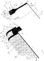
- FIG. 1 shows the area around the first end 3 of a preferred embodiment of a coupling closure according to the invention 1.
- the coupling closure 1 is composed of a first closure strip 5, a second closure strip 7 and the coupling closure 9.
- the first and second closure strips can be integral with the front and rear side wall be connected to a flexible bag.
- the cross section of the first and second closure elements according to the invention (in YZ plane) is initially constant starting from the plant side. Accordingly, both the end stops and a portion of the holding portions (apart from the recess 61) have a substantially constant cross section (in the Y direction). Beginning at the edges 41 and 43, the first and second sealing strips taper, respectively, until they have reached a relatively thin-walled cross-section.
- the minimum cross-section obtained is maintained for a certain length.
- the taper affects the contour of the outer wall of the closure strip, but not the contour of the inner wall.
- the inner wall of the closure strips can, as shown, preferably lay in a flat plane.
- the tapered portions of the closure strips are preferred weld surfaces for flexible bag edges of environmentally sealed containers.
- the first closure strip 5 and the second closure strip 7 are provided with end stops 15 and 17 at their respective first ends 3.
- the first closure strip 5 has a first closure element 19 in the form of a longitudinal groove
- the second closure strip 7 has a second closure element 21 in the form of a longitudinal spring.
- the groove 19 as well as the spring 21 are respectively mounted on the abutment side 23 and 25 of the first and second closure strip 5 and 7 respectively.
- the first and second closure strips 5 and 7 have retaining sections 27 and 29 at least at the first end 3.
- the closure strips 5 and 7 have a longitudinal alignment between the first end 3 and the second end 31 (not shown), i. the abutment sides 23 and 25 extend between the first and second ends in the longitudinal direction (X-direction).
- each closure strip has a thickness or width (distance between the respective outer sides 33, 35 and inner sides 37, 39 of the first and second closure strip (Y-direction).)
- each closure strip or the base body of the closure strip also has transverse to the longitudinal direction over a height extent (Z-direction), which is characterized on one side by the plant sides 23 and 25 and on the other side by the edges 75 and 77.
- Retaining portions 27 and 29 extend beyond the end stops 15 and 17 of the first and second closure strips 5, 7, respectively. These holding portions constitute extensions of the closure strips 5, 7 in longitudinal alignment.
- the respective holding portions 27 and 29 set in the Z direction where the stops 15 and 17 stop.
- the end stops 15 and 17 at a right angle in the holding sections 27 and 29 over.
- the outer and inner sides 33a, 35a and 37a, 39a of the holding portions 27, 29 generally form seamlessly a uniform surface with the inner and outer sides 33, 37; 35, 39 of the closure strips beyond the end stops.
- these outer and inner sides of the holding portions by a contact surface 45, 47, which extends parallel to the contact side 23, 25 of the first and second closure strip 5, 7, respectively.
- the inner sides 37a, 39a of the holding portions 27, 29 of the first and second closure strip 5, 7 are also close to each other can be applied, and preferably firmly connected. Inserting the inner sides 37, 39 of the first and second closure strip 5, 7 close to each other, so that the respective first and second ends 3, 31 and thus the respective end stops 15, 17 are adjacent to each other, the surfaces of the respective end stops lie in a common curved or plan, especially plan level, as in Fig. 1 shown.
- the two end stops 15, 17 of first and second closure strip 5, 7 uniformly dimensioned at least in the Z direction, so that the contact surfaces 45, 47 of the holding portions 27, 29 of the first and second closure strip and the plant sides 23, 25 of the first and second closure strip 5, 7 a curved or planar plane, in particular to form a plane plane.
- the closure 1 has a coupling closure 9.
- This coupling closure 9 has a longitudinal extension in the form of a strip 49 between the first and second end like the closure strips.
- This strip 49 is provided with a support side 51 adjacent to it in a longitudinal orientation to each other third and fourth closure elements 53, 55 are present.
- the third shutter member 53 is a spring and the fourth shutter member 55 is a groove.
- the third shutter member 53 is complementary to the first shutter member 19 in the form of a groove of the first shutter bar 5.
- the fourth shutter member 55 is complementary to the second shutter member 21 in the form of a spring of the second closure strip 7.
- the coupling closure 9 At the first end 3a of the coupling closure 9 there is an end stop 57 which extends at the first end between the support side 51 and the side 59 opposite the support side.
- the first and third 19, 53 and second and fourth closure elements 21, 55 have been coordinated in such a way that the tineumble 23, 25 of the first and second sealing strip in each case rest sealingly on the support side 51 of the coupling closure 9.
- the distance between the third and fourth closure element 53, 55 of the coupling closure 9 and the thickness of the first and second closure element 19, 21 have been selected such that in the closed, ie coupled state, the respective inner sides 37, 39 of first and second closure strip 5, 7 sealingly abut each other.
- the holding sections 27, 29 are also each equipped with a guide element 61, the operation of which will be described in more detail below.
- the thickness or height of the end stop 57 of the coupling closure 9 is substantially equal to the height of the end stops 15, 17 (also in Z-orientation) of the first and second closure strip.
- the thickness of the closure strips 5, 7 (in the Y direction) in the region of the end stops preferably greater than the thickness in the region of the welding surfaces 11, 13 for the subsequent bag walls.
- the transition from closure strip to bag wall can be made jumpy continuously.
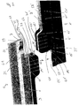
- FIG. 2 shows two coupling closures 1, 1 'according to the invention shortly before the docking operation.
- the docking operation has in an initial stage to the goal, the end stops 15, 17 of the first and second closure strip 5, 7 of the first coupling closure 1 with the end stop 57 'of the coupling closure 9' of the second coupling closure 1 'and the end stops 15', 17 'of first and second closure strip 5 ', 7' of the second closure 1 'with the end stop 57 of the coupling closure 9 of the first coupling closure 1 in such a way to bear that the complementary first closure elements 19, 19' of the first and second coupling closure 1, the first 'and the complementary second closure elements 21, 21' of the first and second coupling closure 1, 1 'by mutual displacement of the two coupling closures 1, 1' according to the invention or the coupling closures 9; 9 'and / or closure strips 15, 17; 15 ', 17' can be coupled together in longitudinal alignment.
- first and second coupling closure 1, 1 ' requires that the complementary first closure elements 19, 19' and the complementary second closure elements 21, 21 'of the first and second coupling closure engage each other unhindered, whereby the respective coupling closures 9, 9' be successively forced out of their connection with these closure elements.
- the dimensions of the end stops 15 ', 17' of the first and second closure strip 5 ', 7' of the second coupling closure 1 'on the end stop 57 of the coupling closure 9 of the first coupling closure 1 are tuned.
- the inner sides of the indentation 67, 67 'forming side walls 63, 65; 63 ', 65' of the coupling closures 9, 9 'of the first and second coupling closure 1, 1' are equipped with guide elements 71, 71 'which are in complementary guide elements 61 and 61' on the outer sides 33, 33 'of the respective holding portions 25, 27 and 25 ', 27' engage in docking.
- the position of these complementary guide elements 61, 71 'and 61', 71 is selected such that the complementary first and second closure elements to be coupled to the first and second closure strips of the first and second coupling closure are unproblematically feasible.
- the indentations 67, 67 'of the coupling closure 9 forming side walls 63, 65 also have the purpose to serve as a preferred grip or breakpoints in particular manual docking.
- the first coupling closure 1 and the coupling closure 9 'of the second coupling closure 1' a particularly reliable docking be accomplished. Because in this way the respectively abutting closure strips of the coupling closures according to the invention are taken safely and reliably during docking.
- FIG. 3 shows a docking device 101 according to the invention, in which the two coupling closures 1, 1 'according to the invention are coupled in the region of their respective adjacent first ends 3, 3'.
- This arrangement is obtained in that the coupling closures 1, 1 ', as in FIG. 2 indicated by the arrow symbols to be moved towards each other to the mutual attachment.
- the coupling closures 9, 9 'of the first and second coupling closure 1, 1' are made of flexible plastics in the illustrated embodiment, as well as the closure strips 5, 5 ', 7, 7' of the first and second coupling closure 1, 1 '.
- the use of complementary guiding elements on the insides of the side walls of the indentation has proven to be particularly useful.
- Particularly preferred is such an embodiment, in which the indentations 67 of the coupling closure 9 forming side walls 63, 65 have on their opposite inner sides further clamping or holding elements.
- These clamping or holding elements can, for example, as in FIG. 1 . 2 . 3 . 4 shown, in the direction of the respective opposite side wall facing projections 73, which are arranged as far away from the support side 51 opposite side 59, be.
- FIG. 4 shows a docking device 101 according to the invention in the coupled state.
- first closure strips 5, 5 'of the first and second coupling closure 1, 1' via their complementary first closure elements 19, 19 'and the second closure strips 7, 7' of the first and second coupling closure 1, 1 'via their complementary second closure elements 21, 21 'sealingly connected to each other over their entire length in longitudinal extent.
- the respective coupling closures 9, 9 'of the first and second coupling closure 1, 1' via the holding portions 27, 29 and 27 ', 29' connected to the respective closure strips.
- the closure elements 53, 55; 53 ', 55' of the coupling closures 9, 9 'in this embodiment are no longer in engagement with the closure elements of the first and the second coupling closure 1, 1' before.
- the inner sides 35, 39; 35 ', 39' of the first and second closure strips 5, 7; 5 ', 7' of the coupling closures 1, 1 ' according to the invention in the region of the end stops and in particular also in the region of the inner sides of the holding sections 27, 29; 27 ', 29' permanently sealed, for example glued or integrally connected.
- the method according to the invention for emptying or loading and / or transferring bulk material with the aid of the inventive coupling fasteners 1, 1 'or the docking device 101 according to the invention will be described below on the basis of the drawings discussed above.
- the first coupling closure 1 according to the invention as in FIG. 3 reproduced, the opening of an inliner closes, as it is used for example in so-called big bags for products used in the food industry products.
- the second coupling closure 1 'according to the invention should in the present case represent the opening of a flexible filling hose which is connected to a storage container.
- the coupling closures 1, 1 'present in the closed state are in the range their end stops 15, 17 to be coupled; 15 ', 17', as in the Figures 2 and 3 reproduced, led together.
- the end stops are at this stage of the process in such a way that the first closure element 19 of the first closure strip 5 of the first coupling closure 1 in the complementary first closure element 19 'of the first closure strip 5' of the second coupling closure 1 'and the second closure element 21 of the second closure strip of the first coupling closure 1 engage in the complementary second closure element 21 'of the second closure strip 7' of the second coupling closure 1 '.
- the docking of the two coupling closures 1, 1 'according to the invention can now be accomplished by holding the side walls 63, 65 of the indentation 67 of the coupling closure 9 of the first coupling closure 1 in order to secure the closure strips 5', 7 'of the second coupling closure 1' left in the Figure 4 ) over the closure strips 5, 7 of the first coupling closure 1 to pull.
- the plant sides slide 23, 23 ', 25, 25' of the first and second coupling closure 1, 1 'one above the other.
- the side walls 63 ', 65' of the coupling closure 9 'of the second coupling closure 1' can be kept to the first and second closure strips 5, 7 of the first coupling closure 1 (to the right in FIG. 3 ), as described above, with the closure strips 5 ', 7' of the second coupling closure 1 'to connect. Furthermore, it is possible by holding the side walls 63, 65; 63 ', 65' of the coupling closures 9, 9 'of the first and second coupling closure 1, 1', the closure strips of these closures relative to each other to move toward each other. In each of the preceding variants, a coupled docking device 101, as in FIG FIG. 4 shown, received.
- This docking device can now be separated again, namely environmentally sealed, in that the third and fourth closure elements 53, 55 of the first coupling closure 1 are reintroduced into the complementary first and second closure elements 19, 21 of the first coupling closure 1.
- the first and second closure elements 19 ', 21' of the second coupling closure 1 ' are automatically reinserted into the complementary third and fourth closure elements 53', 55 'of the second closure. Accordingly, the coupling closures 1, 1 'to be coupled are automatically opened during the docking operation, while they are automatically closed again during decoupling.
- bulk material can thus be removed from a storage container, e.g. a silo to be filled into the inliner of a big bag. If the filling process is completed and no further bulk material material is transferred, as described above, the docking device can be decoupled again. During the entire process, it is ensured that the bulk material to be filled into the inliner neither escapes to the outside nor can components from outside contaminate the bulk material.
- a storage container e.g. a silo to be filled into the inliner of a big bag.
Abstract
Description
Die vorliegende Erfindung betrifft einen Kupplungsverschluß für ein flexibles Gebinde, eine Andockeinrichtung für flexible Gebinde, ein Verfahren zum Entleeren, Be- und/oder Umfüllen von Schüttgut aus flexiblen Gebinden und zwei umweltdicht gekoppelte flexible Gebinde.The present invention relates to a coupling closure for a flexible container, a docking device for flexible containers, a method for emptying, loading and / or decanting of bulk material from flexible containers and two environmentally sealed coupled flexible container.
An den Transfer von Schüttgütern in oder aus Gebinden werden in der lebensmittel- und pharmazeutischen Industrie hohe Qualitätsanforderungen unterstellt. Denn einerseits darf die Umgebung nicht mit dem zuweilen gesundheitsschädlichen Schüttgut kontaminiert werden, andererseits sind Bestandteile aus der Umgebungsluft oder Luft als solche in umweltdichter Weise von dem Schüttgut beim Transferprozeß fernzuhalten. Im übrigen sind auch bei weniger problematischem Schüttgut die Anforderungen an kontaminationsfreies Arbeiten in der lebensmittelverarbeitenden, der chemischen und der pharmazeutischen Industrie sehr hoch.The transfer of bulk goods into or out of containers requires high quality standards in the food and pharmaceutical industries. Because on the one hand, the environment must not be contaminated with the sometimes harmful bulk material, on the other hand components of the ambient air or air as such are kept away from the bulk material during the transfer process in an environmentally sealed manner. Incidentally, the requirements for contamination-free work in the food processing, the chemical and the pharmaceutical industry are very high even with less problematic bulk.
Für die genannten Zwecke haben sich sogenannte Containment-Andocksysteme auf der Basis der Halbklappen-Technologie, wie beispielsweise in der
Konstruktiv einfacherer Andockeinrichtungen, wie in der
In der deutschen Patentanmeldung mit dem Aktenzeichen
Darüber hinaus sind für weniger anspruchsvolle Anwendungen wiederverschließbare Zippverschlüsse zum reversiblen Verschließen von Plastikbeuteln aus der
Es wäre nun wünschenswert, auf nochmals verbesserte Verschlußsysteme für flexible Beutel zurückgreifen zu können, die für jedwede Beutel- bzw. Öffnungsgrößen gleichermaßen zuverlässig und praktikabel, insbesondere lagevariant, eingesetzt werden können und die zudem ein sicheres, gleichwohl einfacheres Verschließen von Gebinden ermöglichen.It would now be desirable to be able to resort to even more improved closure systems for flexible bags, which can be used for any bag or opening sizes equally reliable and practical, in particular positionally variable, and also allow a safe, yet easier closure of containers.
Daher lag der vorliegenden Erfindung die Aufgabe zugrunde, Verschlüsse für flexible Gebinde verfügbar zu machen, die nicht mit den Nachteilen des Standes der Technik behaftet sind und die insbesondere für jede Gebindegröße, d.h. insbesondere auch für große Gebinde- und Öffnungsgrößen ein sicheres und einfach zu handhabendes Verschließen und Öffnen gewährleisten.It is therefore an object of the present invention to provide flexible container closures which do not suffer from the disadvantages of the prior art and which are particularly suitable for each package size, e.g. especially for large container and opening sizes ensure safe and easy to handle closing and opening.
Demgemäß wurde ein Kupplungsverschluß für ein zumindest abschnittsweise flexibles Gebinde gefunden, umfassend eine erste Verschlußleiste mit einem ersten Ende und einem gegenüberliegenden zweiten Ende in longitudinaler Ausdehnung (X-Richtung), einer Innenseite, einer Außenseite und einer Anlageseite, die die Innen- und Außenseite miteinander verbindet, wobei die Anlageseite in longitudinaler Ausdehnung mindestens abschnittsweise mindestens ein erstes Verschlußelement aufweist; eine zweite Verschlußleiste mit einem ersten Ende und einem gegenüberliegenden zweiten Ende in longitudinaler Ausdehnung, einer Innenseite, einer Außenseite und einer Anlageseite, die die Innen- und Außenseite miteinander verbindet, wobei die Anlageseite in longitudinaler Ausdehnung mindestens abschnittsweise mindestens ein zweites Verschlußelement aufweist, wobei ferner die ersten und zweiten Enden von erster und zweiter Verschlußleiste bei gegenseitiger Anlage der Innenseiten dieser Verschlußleisten jeweils benachbart sind, und wobei die ersten und zweiten Verschlußelemente sich bis zu den benachbarten ersten und/oder den benachbarten zweiten Enden erstrecken; und einen Koppelverschluß, umfassend eine Leiste mit einem ersten und einem zweiten Ende in longitudinaler Ausdehnung, wobei das erste und/oder zweite Ende einen Endanschlag aufweist, und einer Auflageseite, umfassend in longitudinaler Ausdehnung auf der Auflageseite mindestens abschnittsweise ein drittes Verschlußelement, das mit dem ersten Verschlußelement reversibel, insbesondere umweltdicht, gekoppelt oder koppelbar ist, und beabstandet, insbesondere äquidistant beabstandet, hierzu mindestens abschnittsweise ein viertes Verschlußelement, das mit dem zweiten Verschlußelement reversibel, insbesondere umweltdicht, gekoppelt oder koppelbar ist.Accordingly, a coupling closure has been found for an at least partially flexible container, comprising a first closure strip having a first end and an opposite second end in the longitudinal direction (X-direction), an inner side, an outer side and an abutment side, the inner and outer sides together connects, wherein the plant side in the longitudinal extent at least partially has at least one first closure element; a second closure strip having a first end and an opposite second end in longitudinal extent, an inner side, a Outer side and an abutment side, which connects the inside and outside together, wherein the plant side in longitudinal extent at least partially at least a second closure element, further wherein the first and second ends of the first and second closure strip in mutual contact of the insides of these closure strips are adjacent and wherein the first and second closure members extend to the adjacent first and / or adjacent second ends; and a coupling closure comprising a strip having a first and a second end in longitudinal extent, the first and / or second end having an end stop, and a support side comprising, in longitudinal extension on the support side at least in sections, a third closure element connected to the first closure element is reversible, in particular environmentally sealed, coupled or coupled, and spaced, in particular equidistantly spaced, this at least partially a fourth closure element which is reversible, in particular environmentally sealed, coupled or coupled to the second closure element.
Gemäß einer besonders bevorzugten Ausgestaltung ist vorgesehen, daß das erste und/oder zweite Ende des Koppelverschlusses einen Endanschlag, das erste und/oder das zweite Ende der ersten Verschlußleiste einen Endanschlag und das erste Ende und/oder das zweite Ende der zweiten Verschlußleiste einen Endanschlag aufweisen, wobei jeweils benachbarte Enden von Koppelverschluß sowie von erster und zweiter Verschlußleiste einen Endanschlag aufweisen, und daß die ersten und zweiten Verschlußelemente sich bis zu den benachbarten Endanschlägen von erster und zweiter Verschlußleiste und daß die dritten und vierten Verschlußelemente sich bis zum Endanschlag des Koppelverschlusses, der benachbart zu den einander benachbarten Endanschlägen von erster und zweiter Verschlußleiste ist, erstrecken und daß das erste und/oder zweite Ende des Koppelverschlusses einen Endanschlag aufweist.According to a particularly preferred embodiment, it is provided that the first and / or second end of the coupling closure an end stop, the first and / or the second end of the first closure strip an end stop and the first end and / or the second end of the second closure strip have an end stop , wherein each adjacent ends of the coupling closure and the first and second closure strip have an end stop, and that the first and second closure elements to the adjacent end stops of the first and second closure strip and that the third and fourth closure elements to the end stop of the coupling closure, the is adjacent to the adjacent end stops of the first and second closure strip, extend and that the first and / or second end of the coupling closure has an end stop.
Ferner kann erfindungsgemäß vorgesehen sein, daß die erste und/oder zweite Verschlußleiste in longitudinaler Ausrichtung an dem ersten und/oder zweiten Ende einen Halteabschnitt aufweist, enthaltend erste bzw. zweite Anlageflächen sowie eine Innen- und eine Außenseite. Die Innen- und die Außenseite eines Halteabschnitts stehen durch die erste bzw. zweite Anlagefläche miteinander in Verbindung.Furthermore, it can be provided according to the invention that the first and / or second closure strip has a holding section in longitudinal alignment at the first and / or second end, containing first and second contact surfaces and an inner and an outer side. The inside and the outside of a holding portion are connected by the first and second abutment surface with each other.
Schüttgüter, die mit Hilfe des erfindungsgemäßen Kupplungsverschlusses umweltdicht transferiert werden können, umfassen sämtliche fluiden Systeme, die schüttbar sind. Hierbei kann es sich um flüssiges Schüttgut wie auch um partikuläres Schüttgut, beispielsweise fein- oder grobkörnig, handeln.Bulk goods that can be environmentally sealed with the help of the coupling closure according to the invention include all fluid systems that are pourable. This may be liquid bulk material as well as particulate bulk material, for example fine or coarse-grained.
Als flexible Gebinde kommen beispielsweise Beutel oder Säcke sowie Fördermittel, beispielsweise in Form von Schläuchen oder Schlauchelementen, in Frage. Bevorzugte Gebinde stellen auch sogenannte Inliner, z.B. für Big Bags, dar, die beispielsweise in Vorratstanks für flüssige oder partikuläre Schüttgüter zum Einsatz kommen. Diese Gebinde können z.B. auch aus einem Plastik-, Textil- und/oder Vliesmaterial gefertigt sein. Zweckmäßigerweise ist derjenige Abschnitt des Gebindes in der Nähe des Öffnungsrandes flexibel ausgestaltet, der mit dem Kupplungsverschluß verbunden ist. Der erfindungsgemäße Kupplungsverschluß dient folglich in seiner ersten Funktion als Verschluß für die Öffnungen flexibler Gebinde. In seiner zweiten Funktion dient er zum Kuppeln bzw. Andocken an einen komplementären Kupplungsverschluß unter Ausbildung einer insbesondere umweltdichten Andockeinrichtung, durch die Schüttgut problemlos von einem ersten Gebinde in ein zweites Gebinde transportiert werden kann.As flexible containers, for example, bags or sacks as well as conveying means, for example in the form of hoses or hose elements, come into question. Preferred containers also provide so-called inliners, e.g. for big bags, which are used, for example, in storage tanks for liquid or particulate bulk goods. These containers can e.g. also be made of a plastic, textile and / or nonwoven material. Conveniently, that portion of the container in the vicinity of the opening edge is designed to be flexible, which is connected to the coupling closure. The coupling closure according to the invention consequently serves in its first function as a closure for the openings of flexible containers. In its second function, it serves for coupling or docking to a complementary coupling closure to form a particular environmentally sealed docking device, can be easily transported by the bulk material from a first container in a second container.
Die Größe der Kupplungsverschlüsse ist in weiten Bereichen an die Öffnungsgröße der zu verschließenden bzw. zu koppelnden Gebinde anpaßbar. Beispielsweise können die erfindungsgemäßen Kupplungsverschlüsse über Öffnungen mit einem Durchmesser im Bereich von 10 bis 200 cm, vorzugsweise im Bereich von 15 bis 100 cm, aufweisen. Demgemäß lassen sich mit den erfindungsgemäßen Kupplungsverschlüssen Gebinde, insbesondere Beutel und Fördermittel, z.B. Schläuche verschließen bzw. andocken, die über Öffnungsdurchmesser im Bereich von 10 bis 200 cm, vorzugsweise von 15 bis 100 cm verfügen.The size of the coupling closures can be adapted in many areas to the opening size of the containers to be closed or coupled. For example, the coupling closures according to the invention can have openings with a diameter in the range of 10 to 200 cm, preferably in the range of 15 to 100 cm. Accordingly, containers, in particular bags, can be used with the coupling closures according to the invention and conveying means, eg closing or docking hoses, which have opening diameters in the range from 10 to 200 cm, preferably from 15 to 100 cm.
Die erfindungsgemäßen Kupplungsverschlüsse bzw. die ersten und zweiten Verschlußleisten wie auch der Koppelverschluß verfügen über eine longitudinale Ausdehnung, jeweils begrenzt durch das erste und das gegenüberliegende zweite Ende des Kupplungsverschlusses bzw. der Verschlußleisten und des Koppelverschlusses. Die Länge eines solchen Kupplungsverschlusses, d.h. der Abstand zwischen dem ersten und dem zweiten Ende kann, was nachweislich ein besonderer Vorteil der erfindungsgemäßen Kupplungsverschlüsse ist, in sehr weiten Bereichen variieren und beispielsweise im Bereich von 10 bis 400 cm, vorzugsweise im Bereich von 15 bis 315 cm liegen. Liegen der Kupplungsverschluß bzw. die ersten und zweiten Verschlußleisten sowie der Koppelverschluß in longitudinaler Ausrichtung auf einer X-Achse, so kann auch die transversale bzw. Querausdehnung, d.h. senkrecht zur X-Achse, in weiten Bereichen variieren. Beispielsweise kann die Höhe des Kupplungsverschlusses, d.h. die Ausdehnung in Z-Richtung im Bereich von 10 bis 130 mm, vorzugsweise von 20 bis 50 mm, liegen. Hierbei nimmt die Höhe der Verschlußleisten in der Regel einen Wert im Bereich von 6 bis 100 mm, vorzugsweise von 16 bis 40 mm, und die Höhe des Koppelverschlusses bzw. der Leiste des Koppelverschlusses eine Höhe im Bereich von 4 bis 30 mm, vorzugsweise von 4 bis 10 mm, an. Die Höhe des Endanschlags von erster und zweiter Verschlußleiste kann beispielsweise im Bereich von 4 bis 10 mm liegen. Vorzugsweise stimmt diese Höhe des Endanschlags von erster und zweiter Verschlußleiste mit der Höhe des Koppelverschlusses bzw. der Leiste des Koppelverschlusses eines anzudockenden zweiten Kupplungsverschlusses überein, insbesondere wenn die Verschlußleisten über Halteabschnitte verfügen, die in X-Richtung über die Endanschläge hinausgehen. Die Breite der ersten und zweiten Verschlußleisten, d.h. die Ausdehnung in Y-Richtung, liegt jeweils vorzugsweise im Bereich von 2 bis 10 mm, insbesondere von 2 bis 4 mm, während die Breite des Koppelverschlusses vorzugsweise im Bereich von 5 bis 30 mm, insbesondere von 5 bis 10 mm, liegt. In einer zweckmäßigen Ausgestaltung ist der Koppelverschluß breiter als die beiden an ihren Innenseiten benachbarten ersten und zweiten Verschlußleisten, so daß die Auflageseite des Koppelverschlusses an ihren Längsrändern über die Anlageseiten der Verschlußleisten hervorragt. Die X-, Y- und Z-Dimensionen entsprechen hierbei den Achsen eines kartesischen Koordinatensystems.The coupling closures according to the invention or the first and second closure strips as well as the coupling closure have a longitudinal extent, each bounded by the first and the opposite second end of the coupling closure or the closure strips and the coupling closure. The length of such a coupling closure, ie the distance between the first and the second end, which is demonstrably a particular advantage of the coupling closures according to the invention, can vary within very wide ranges and for example in the range of 10 to 400 cm, preferably in the range of 15 to 315 cm lie. If the coupling closure or the first and second closure strips as well as the coupling closure in longitudinal alignment on an X-axis, then the transverse or transverse extent, ie perpendicular to the X-axis, vary within wide ranges. For example, the height of the coupling closure, ie the extension in the Z direction in the range of 10 to 130 mm, preferably from 20 to 50 mm, lie. In this case, the height of the closure strips usually takes a value in the range of 6 to 100 mm, preferably 16 to 40 mm, and the height of the coupling closure or the bar of the coupling closure a height in the range of 4 to 30 mm, preferably from 4 up to 10 mm, on. The height of the end stop of the first and second closure strip may for example be in the range of 4 to 10 mm. Preferably, this height of the end stop of the first and second closure strip coincides with the height of the coupling closure or the strip of the coupling closure of a second coupling closure to be docked, in particular if the closure strips have holding sections which extend beyond the end stops in the X direction. The width of the first and second closure strips, ie the extent in the Y direction, is in each case preferably in the range from 2 to 10 mm, in particular from 2 to 4 mm, while the width of the coupling closure preferably in the range of 5 to 30 mm, in particular of 5 to 10 mm. In an expedient embodiment of the coupling closure is wider than the two adjacent to their inner sides first and second closure strips, so that the support side of the coupling closure protrudes at its longitudinal edges on the Anlageseiten the closure strips. The X, Y and Z dimensions correspond to the axes of a Cartesian coordinate system.
Die erste und die zweite Verschlußleiste des Kupplungsverschlusse bilden einen Umfangsrand aus, der durch gegenseitiges Anlegen der Innenseiten dieser Verschlußleisten dichtend verschlossen werden kann. Die Verschlußleisten sind vorzugsweise aus einem nicht starren Material gefertigt, insbesondere einem Kunststoffmaterial. Geeignete Materialien für die Verschlußleisten sind beispielsweise Polyethylen und Polypropylen. Grundsätzlich kommen alle dem Fachmann bekannten thermoplastischen Werkstoffe, auch in Form von Mischungen, in Betracht. Selbstverständlich können auch Verschlußleisten eingesetzt werden, die weniger flexibel ausgebildet sind, solange ein hinreichend großer Querschnitt für den Durchtritt von Schüttgut reversibel einstellbar ist.The first and the second closure strip of the coupling closure form a peripheral edge, which can be sealed by mutual application of the insides of these closure strips. The closure strips are preferably made of a non-rigid material, in particular a plastic material. Suitable materials for the closure strips are, for example, polyethylene and polypropylene. In principle, all thermoplastic materials known to the person skilled in the art, also in the form of mixtures, come into consideration. Of course, also sealing strips can be used, which are less flexible, as long as a sufficiently large cross-section for the passage of bulk material is reversibly adjustable.
Für den Koppelverschluß können sowohl flexible als auch starrere Materialien, beispielsweise aus Kunststoff oder Metall eingesetzt werden. Geeignete flexible Materialien umfassen z.B. Polyolefine wie Polyethylen, insbesondere LD-Polyethylen, Polyvinylchlorid und Polyester. Als starrerer Kunststoffmaterialien sind z.B. Polyamide, Polystyrol, Polypropylen und Polyoxyalkylene geeignet. Besonders bevorzugt sind solche Materialien, mit denen sich der Koppelverschluß, insbesondere die Leiste des Koppelverschlusses, mit Hilfe eines Strangpreßprofils mittels Extrusion herstellen läßt, z.B. Polyethylen. Die Leiste des Koppelverschlusses kann im Grunde jedwede Form annehmen, solange sichergestellt ist, daß ein Andocken an einen komplementären Kupplungsverschluß damit bewerkstelligt werden kann. Bevorzugt ist die Auflageseite des Koppelverschlusses flach ausgestaltet. Die Grundform der Leiste, wenn von oben auf die Auflageseite geschaut wird, kann grundsätzlich beliebig geformt sein und beispielsweise geradlinig, gebogen oder wellenförmig sein. Vorzugsweise ist der Verlauf der Leiste, wenn von oben auf die Leiste geschaut wird, geradlinig. Dieses trifft vorzugsweise auch auf die auf der Auflageseite vorliegenden dritten und vierten Verschlußelemente des Koppelverschlusses zu. Die dritten und vierten Verschlußelemente erstrecken sich ebenso wie die ersten und zweiten Verschlußelemente der Verschlußleisten zumindest an einem Ende unmittelbar bis zu den jeweiligen Endanschlägen.For the coupling closure both flexible and more rigid materials, such as plastic or metal can be used. Suitable flexible materials include, for example, polyolefins such as polyethylene, especially LD polyethylene, polyvinyl chloride and polyester. As a more rigid plastic materials such as polyamides, polystyrene, polypropylene and polyoxyalkylenes are suitable. Particularly preferred are those materials with which the coupling closure, in particular the strip of the coupling closure, can be produced by means of extrusion by means of an extruded profile, for example polyethylene. The bar of the coupling closure can basically take any form, as long as it is ensured that docking with a complementary coupling closure can be accomplished with it. Preferably, the support side of the coupling closure is designed flat. The basic shape of the bar when viewed from above on the support side, can basically be arbitrarily shaped and, for example, be rectilinear, curved or wavy. Preferably, the course of the bar, when viewed from the top of the bar, is straight. This preferably also applies to the present on the support side third and fourth closure elements of Coupling closure to. The third and fourth closure elements extend as well as the first and second closure elements of the closure strips at least at one end directly to the respective end stops.
Die Anlageseiten der Verschlußleisten sind vorzugsweise derart ausgeformt, daß sie bei Anlage an die Auflageseite des Koppelverschlusses einen dichten Abschluß bilden können.The plant sides of the closure strips are preferably formed such that they can form a tight seal when applied to the support side of the coupling closure.
Der Querschnitt der Verschlußleisten kann grundsätzlich beliebige Formen annehmen. Vorzugsweise sind die Querschnittsformen der ersten und zweiten Verschlußleiste in der Weise aufeinander und/oder auf den Koppelverschluß abgestimmt, daß ein umweltdichter Kupplungsverschluß resultiert. Beispielsweise können die ersten und zweiten Verschlußleisten in einer Ausführungsform einen quadratischen oder rechteckigen Querschnitt aufweisen. Gemäß einer weiteren, bevorzugten Ausgestaltung verjüngt sich der Querschnitt von erster und/oder zweiter Verschlußleiste, je weiter man sich von der Anlageseite entfernt. Dieses kann kontinuierlich oder diskontinuierlich sein. Beispielsweise kann die Querschnittsausdehnung im Bereich des Endanschlages konstant sein und erst anschließend eine Verjüngung des Querschnitts einsetzen. Besonders bevorzugt setzt diese Verjüngung nicht unverzüglich ein, sondern erst an einer noch weiter von der Anlageseite entfernten Stelle. Bei dieser Ausführungsform verfügt somit auch der Halteabschnitt über ein Querschnittsegment, das zumindest teilweise eine einheitliche Querschnittsbreite aufweist. Während z.B. die einheitliche Breite (in Y-Richtung) sich über die gesamte Ausdehnung des Endanschlags erstreckt, z.B. über eine Ausdehnung von 5 bis 10 mm, kann diese unveränderte Querschnittausdehnung noch für weitere 5 bis 10 mm beibehalten werden, bevor sich der Querschnitt zu verjüngen beginnt. Die Verjüngung des Querschnitts verläuft vorzugsweise derart, daß die Innenseite der ersten und/oder zweiten Verschlußleiste im wesentlichen auf einer Geraden verbleibt. Insbesondere die sich entfernt von der Anlageseite verjüngenden Abschnitte der Verschlußleisten eignen sich als Anbindungsfläche, vorzugsweise Anschweißfläche, für die Ränder von mit den erfindungsgemäßen Kupplungsverschlüssen zu verbindenen Gebinden. Die Anbindung der flexiblen Gebinderänder an die Anbindungsfläche bzw. an die Verschlußleiste kann mit dem Fachmann bekannten Mitteln erfolgen, beispielsweise mittels Verklebens, Ultraschall-, Vibration- oder Laserschweißens.The cross section of the closure strips can basically assume any desired shapes. Preferably, the cross-sectional shapes of the first and second closure strip are matched to each other in such a way and / or on the coupling closure, that an environmentally sealed coupling closure results. For example, in one embodiment, the first and second closure strips may have a square or rectangular cross-section. According to a further, preferred embodiment, the cross section of the first and / or second sealing strip tapers the farther one moves away from the contact side. This can be continuous or discontinuous. For example, the cross-sectional extent in the region of the end stop may be constant and only then use a taper of the cross section. Particularly preferably, this rejuvenation does not start immediately, but only at a location further away from the plant side. In this embodiment, therefore, also the holding portion has a cross-sectional segment, which at least partially has a uniform cross-sectional width. For example, while the uniform width (in the Y direction) extends over the entire extension of the end stop, for example over an extent of 5 to 10 mm, this unchanged cross-sectional extension can be maintained for a further 5 to 10 mm before the cross section is tapered starts. The taper of the cross section is preferably such that the inside of the first and / or second closure strip remains substantially on a straight line. In particular, the portions of the closure strips that taper away from the contact side are suitable as attachment surfaces, preferably welding surfaces, for the edges of containers to be connected to the coupling fasteners according to the invention. The connection of the flexible Binder edges to the connection surface or to the closure strip can be done by means known to those skilled, for example by means of gluing, ultrasonic, vibration or laser welding.
Demgemäß sieht eine Weiterentwicklung der erfindungsgemäßen Kupplungsverschlüsse ferner vor, daß die erste und/oder zweite Verschlußleiste beabstandet von der Anlageseite (in Z-Richtung) eine Anbindungsfläche, insbesondere Anschweißfläche, für den Öffnungsrand von Gebinden aufweist, insbesondere mit einer Dicke (in Y-Richtung), die zumindest abschnittsweise geringer ist als die Dicke der ersten oder zweiten Verschlußleiste im Bereich der Endanschläge. Selbstverständlich können die Gebinderänder auch bis zur Anlageseite und darüber hinaus reichen und z.B. vollflächig mit den Innenseiten der Verschlußleisten verbunden sein. Alternativ können die Gebinderänder auch mit den Außenseiten der Verschlußleisten verbunden sein.Accordingly, a further development of the coupling closures according to the invention also provides that the first and / or second closure strip spaced from the contact side (in the Z direction) has a connection surface, in particular welding surface, for the opening edge of containers, in particular with a thickness (in the Y direction ), which is at least partially smaller than the thickness of the first or second sealing strip in the region of the end stops. Of course, the container edges may also extend to the plant side and beyond, and e.g. be connected over the entire surface with the insides of the closure strips. Alternatively, the container edges may also be connected to the outsides of the closure strips.
Gemäß einer bevorzugten Ausgestaltung ist vorgesehen, daß die erste und/oder zweite Verschlußleiste in longitudinaler Ausrichtung an dem ersten und/oder zweiten Ende über den ersten bzw. zweiten Endanschlag hinaus und in transversaler Ausrichtung (Z-Richtung) entfernt von den Anlageseiten und im Anschluß an den ersten und/oder zweiten Endanschlag in Form von Halteabschnitten, enthaltend eine sich von dem ersten und/oder zweiten Endanschlag erstreckende erste bzw. zweite Anlagefläche sowie eine Innen- und eine Außenseite, verlängert sind, insbesondere derart daß der erste und/oder zweite Endanschlag mit dem Endanschlag eines Koppelverschlusses eines zweiten Kupplungsverschluß zur Anlage bringbar sind. Die Halteabschnitte ragen in X-Richtung beispielsweise in einer Länge von 10 bis 50 mm, vorzugsweise von 20 bis 40 mm, über den jeweiligen Endanschlag hinaus.According to a preferred embodiment it is provided that the first and / or second closure strip in longitudinal alignment at the first and / or second end beyond the first and second end stop and in transverse alignment (Z direction) away from the plant sides and in connection to the first and / or second end stop in the form of holding sections, containing a first and / or second end stop extending first and second contact surface and an inner and an outer are extended, in particular such that the first and / or second End stop can be brought to the end stop of a coupling closure of a second coupling closure to the plant. The holding portions protrude in the X direction, for example in a length of 10 to 50 mm, preferably from 20 to 40 mm, beyond the respective end stop.
Liegen die ersten und zweiten Verschlußleisten mit ihren Innenseiten dicht aneinander an und bilden die Anlageseiten dieser Verschlußleisten im wesentlichen eine gemeinsame Fläche aus, können die ersten und zweiten Verschlußelemente in der Regel ohne weiteres in die komplementären dritten bzw. vierten Verschlußelemente eingeschoben werden. Indem man die Endanschläge der ersten und zweiten Verschlußleisten an den Endanschlag des Koppelverschlusses eines komplementären Kupplungsverschlusses anlegt sowie gleichzeitig die Endanschläge von erster und zweiter Verschlußleise eines zweiten Kupplungsverschlusses an den Endanschlag des ersten Kupplungsverschlusses, können die jeweils komplementären ersten und zweiten Verschlußelemente von erster und zweiter Verschlußleiste unter Ausbildung einer dichten Andockeinrichtung ineinander geschoben werden. Gleichzeitig werden die dritten und vierten Verschlußelemente der Koppelverschlüsse nach und nach freigesetzt. Dieser Andockvorgang kann wesentlich durch die vorangehend beschriebenen Halteabschnitte verbessert und vereinfacht werden. Die Halterabschnitte stellen eine Verlängerung der Verschlußleisten beabstandet von deren Anlageseiten dar, und zwar unter Beibehaltung der ersten und zweiten Endanschläge. Demgemäß verfügen die Halteabschnitte nicht über eine durchgehende Anlageseite mit den Verschlußleisten, vielmehr ist die Auflagefläche der Halteabschnitte in Richtung der anzubindenden Beutelwand verschoben und mündet üblicherweise in einem Winkel, vorzugsweise rechtwinklig, in den ersten bzw. zweiten Endanschlag. Bevorzugt ist die Auflagefläche des Halteabschnitts einer Verschlußleiste parallel zu deren Anlageseite.Are the first and second closure strips with their inner sides close to each other and form the Anlageseiten this closure strips essentially a common surface, the first and second closure elements can usually readily in the complementary third or fourth closure elements are inserted. By applying the end stops of the first and second closure strips to the end stop of the coupling closure of a complementary coupling closure and at the same time the end stops of the first and second locking of a second coupling closure to the end stop of the first coupling closure, the respective complementary first and second closure elements of the first and second closure strip are pushed together forming a tight docking device. At the same time, the third and fourth closure elements of the coupling closures are gradually released. This docking operation can be substantially improved and simplified by the holding sections described above. The holder portions provide an extension of the closure strips spaced from their plant sides, while maintaining the first and second end stops. Accordingly, the holding portions do not have a continuous contact side with the closure strips, but the support surface of the holding portions is displaced in the direction of the bag wall to be connected and usually opens at an angle, preferably at right angles, in the first and second end stop. Preferably, the bearing surface of the holding portion of a closure strip is parallel to the plant side.
Die Halteabschnitte erleichtern die Bedienung der erfindungsgemäßen Kupplungsverschlüsse nochmals beträchtlich. Beim manuellen Andocken komplementärer Kupplungsverschlüsse lassen sich die Auflageflächen der Halteabschnitte auf die der Auflagenseite des Koppelverschlusses gegenüberliegende Seite auflegen, wodurch sich die Anlageseiten der Verschlußleisten des anzudockenden Kupplungsverschlusses in etwa auf einer Höhe befinden, auf der die Verschlußleisten bzw. deren erste und zweite Verschlußelemente direkt in die komplementären ersten und zweiten Verschlußelemente des ersten Kupplungsverschlusses eingeführt werden können.The holding sections facilitate the operation of the coupling closures according to the invention again considerably. When manually docking complementary coupling closures, the bearing surfaces of the holding sections can be placed on the opposite side of the coupling closure side, whereby the Anlageseiten the closure strips of the coupling to be docked closure are approximately at a level on which the closure strips or their first and second closure elements directly into the complementary first and second closure elements of the first coupling closure can be inserted.
Dabei kann insbesondere vorgesehen sein, daß der Koppelverschluß in transversaler Ausrichtung (Z-Richtung) zwischen der Auflageseite und der der Auflageseite gegenüberliegenden Seite im Bereich des Endanschlags eine Dicke aufweist, die dem Abstand zwischen der Anlagefläche des Halteabschnitts der ersten und/oder zweiten Verschlußleiste, an der Stelle, wo die Anlagefläche den ersten bzw. zweiten Endanschlag trifft, und der Anlageseite von erster bzw. zweiter Verschlußleiste im wesentlichen entspricht.It can be provided in particular that the coupling closure in transverse alignment (Z direction) between the support side and the support side opposite Side in the region of the end stop has a thickness which is the distance between the contact surface of the holding portion of the first and / or second closure strip, at the location where the contact surface meets the first and second end stop, and the contact side of the first and second closure strip in essentially corresponds.
Im allgemeinen kann für komplementäre Verschlußelemente auf Feder/Nut-Verbindungen zurückgegriffen werden. Demgemäß zeichnet sich eine Ausführungsform dadurch aus, daß die Verschlußelemente von erster und zweiter Verschlußleiste jeweils eine Nut darstellen und daß die dritten und vierten Verschlußelemente des Koppelverschlusses jeweils eine Feder darstellen, die zu der Nut der ersten bzw. zweiten Verschlußleiste komplementär ist, so daß Nut und Feder jeweils reversibel, insbesondere umweltdicht, in Eingriff bringbar sind. Gemäß einer weiteren Variante ist vorgesehen, daß die ersten und zweiten Verschlußelemente von erster und zweiter Verschlußleiste jeweils eine Feder darstellen und daß die dritten und vierten Verschlußelemente des Koppelverschlusses eine Nut darstellen, die zu der Feder von erster bzw. zweiter Verschlußleiste komplementär sind, so daß Nut und Feder jeweils reversibel, insbesondere umweltdicht, in Eingriff bringbar sind. Alternativ kann ferner vorgesehen sein, daß das erste Verschlußelement der ersten Verschlußleiste eine Nut und das zweite Verschlußelement der zweiten Verschlußleiste eine Feder darstellen sowie daß das dritte Verschlußelement des Koppelverschlusses eine Feder, die zu der Nut der ersten Verschlußleiste komplementär ist, und das vierte Verschlußelement des Koppelverschlusses eine Nut, die zu der Feder der zweiten Verschlußleiste komplementär ist, darstellen, so daß Nut und Feder jeweils reversibel, insbesondere umweltdicht, in Eingriff bringbar sind.In general can be used for complementary closure elements on spring / groove connections. Accordingly, an embodiment is characterized in that the closure elements of the first and second closure strip each represent a groove and that the third and fourth closure elements of the coupling closure each represent a spring which is complementary to the groove of the first and second closure strip, so that groove and spring each reversible, in particular environmentally sealed, can be brought into engagement. According to a further variant, it is provided that the first and second closure elements of the first and second closure strip each represent a spring and that the third and fourth closure elements of the coupling closure form a groove which are complementary to the spring of the first and second closure strip, so that Both tongue and groove reversible, especially environmentally sealed, can be brought into engagement. Alternatively, it may further be provided that the first closure element of the first closure strip a groove and the second closure element of the second closure strip form a spring and that the third closure element of the coupling closure a spring which is complementary to the groove of the first closure strip, and the fourth closure element of the Coupling closure a groove which is complementary to the spring of the second closure strip represent, so that tongue and groove are each reversible, in particular environmentally sealed, engageable.
Ein Ankuppeln von erstem und zweitem Kupplungsverschluß gelingt dann besonders unproblematisch, wenn die Leiste des Koppelverschlusses im Bereich des ersten und/oder zweiten Endes, insbesondere im Bereich des Endanschlags des ersten und/oder zweiten Endes in longitudinaler Ausrichtung eine Aufnahmevorrichtung, insbesondere eine Einbuchtung, zur Aufnahme des Halteabschnitts eines zweiten Kupplungsverschluß aufweist, insbesondere in Form beabstandeter Seitenwandungen, die sich von der Seite, die der Auflageseite gegenüberliegt, weg erstrecken, insbesondere zumindest abschnittsweise im wesentlichen parallele Wandungen.Coupling of the first and second coupling closure succeeds particularly unproblematic if the strip of the coupling closure in the region of the first and / or second end, in particular in the region of the end stop of the first and / or second end in longitudinal alignment a receiving device, in particular a recess, the Receiving the holding portion of a second coupling closure has, in particular in the form spaced sidewalls, which extend away from the side opposite to the support side, in particular at least partially substantially parallel walls.
Hierbei ist von Vorteil, wenn die Aufnahmevorrichtung, insbesondere mindestens eine Innenseite der beabstandeten Seitenwandungen dieser Aufnahmevorrichtung, mindestens ein Führelement aufweist, das mit einem komplementären Führelement des Halteabschnitts von erster und/oder zweiter Verschlußleiste eines zweiten Kupplungsverschlusses in Eingriff bringbar ist. Die Halteabschnitte liegen im Bereich der ersten und zweiten Enden des erfindungsgemäßen Kupplungsverschlusses vor. An diesen sich gegenüberliegenden Enden werden die Kupplungsverschlüsse regelmäßig mit der Hand ergriffen, um den Andockvorgang zu initiieren. Indem die Koppelverschlüsse mit Einbuchtungen versehen werden, in die die Halteabschnitte korrespondierender Kupplungsverschlüsse eingelegt werden können, können durch Zusammendrücken der Seitenwände dieser Einbuchtungen bei hinreichender Dicke der eingefügten benachbarten ersten und zweiten Halteabschnitte die ersten und zweiten Verschlußleisten bereits gemeinsam bewegt werden. Die aneinander anliegenden, einen Verschluß bildenden ersten und zweiten Verschlußleisten werden dann besonders gut und unproblematisch, wie vorangehend beschrieben, mit einem komplementären Kupplungsverschluß verbunden, wenn die Halteabschnitte beim Andockvorgang nicht mehr aus der Einbuchtung herausrutschen können. Dieses gelingt durch den Einsatz komplementärer Führelemente, die miteinander in Eingriff bringbar sind und somit in einem im wesentlichen arretierten Zustand vorliegen.It is advantageous if the receiving device, in particular at least one inside of the spaced side walls of this receiving device, has at least one guide element which can be brought into engagement with a complementary guide element of the holding portion of the first and / or second closure strip of a second coupling closure. The holding portions are in the region of the first and second ends of the coupling closure according to the invention. At these opposite ends, the coupling closures are regularly gripped by hand to initiate the docking process. By providing the coupling closures with indentations into which the holding portions of corresponding coupling closures can be inserted, the first and second closure strips can already be moved together by compressing the side walls of these indentations with sufficient thickness of the inserted adjacent first and second holding portions. The adjoining, forming a closure first and second closure strips are then particularly well and unproblematically, as described above, connected to a complementary coupling closure when the holding sections during docking can not slip out of the recess. This is achieved by the use of complementary guide elements, which are engageable with each other and thus present in a substantially locked state.
Demgemäß verfügen die erfindungsgemäßen Kupplungsverschlüsse vorzugsweise über mindestens einen Halteabschnitt von erster und/oder zweiter Verschlußleiste mit auf seiner Außenseite mindestens einem Führelement, das mit einem komplementären Führelement des Koppelverschlusses eines zweiten Kupplungsverschlusses in Eingriff bringbar ist. Besonders geeignet sind diejenigen Kupplungsverschlüsse, bei denen die ersten und dritten Verschlußelemente und/oder die zweiten und vierten Verschlußelemente derart aufeinander abgestimmt sind, daß die Anlageseite der ersten bzw. zweiten Verschlußleiste und die Auflageseite des Koppelverschlusses im gekoppelten Zustand zumindest bereichsweise dichtend aneinander anliegen bzw. dichtend aneinander anlegbar sind.Accordingly, the coupling closures according to the invention preferably have at least one holding section of the first and / or second closure strip with on its outer side at least one guide element which can be brought into engagement with a complementary guide element of the coupling closure of a second coupling closure. Particularly suitable are those coupling closures in which the first and third closure elements and / or the second and fourth closure elements so matched to one another are that the contact side of the first and second sealing strip and the support side of the coupling closure in the coupled state at least partially sealingly abut each other or sealingly against each other can be applied.
Erfindungsgemäß ist ferner vorgesehen, daß die dritten und vierten Verschlußelemente einen derartigen Abstand voneinander aufweisen, daß die Innenseiten von erster und zweiter Verschlußleiste im mit dem ersten bzw. zweiten Verschlußelement gekoppelten Zustand zumindest bereichsweise, insbesondere dichtend, aneinander anliegen oder anlegbar sind.According to the invention it is further provided that the third and fourth closure elements have such a distance from each other that the inner sides of the first and second closure strip in the coupled to the first and second closure element state at least partially, in particular sealing, abut each other or can be applied.
Zweckmäßigerweise sind das erste und das zweite Verschlußelement in longitudinaler Ausrichtung im wesentlichen gleich lang. Dieses trifft ebenfalls bevorzugt auf das dritte und das vierte Verschlußelement zu, welche vorzugsweise parallel verlaufen.Conveniently, the first and second closure members in longitudinal alignment are substantially the same length. This also preferably applies to the third and the fourth closure element, which preferably run parallel.
Besonders bevorzugt sind auch Kupplungsverschlüsse, bei denen das erste und das dritte Verschlußelement und/oder das zweite und das vierte Verschlußelement in longitudinaler Ausrichtung im wesentlichen gleich lang sind.Also particularly preferred are coupling closures in which the first and third closure element and / or the second and fourth closure elements in longitudinal alignment are substantially the same length.
Die Vorrichtung zur Aufnahme des Halteabschnitts bzw. der ersten und zweiten Halteabschnitte eines zweiten Kupplungsverschlusses kann einstückig oder separat mit der Leiste des Koppelverschlusses des ersten Kupplungsverschlusses verbindbar oder verbunden sein. Bevorzugt ist diese Vorrichtung, die in einer zweckmäßigen Ausgestaltung die Form einer Einbuchtung annimmt, als separates Bauteil mit der Leiste, insbesondere an deren erstem und/oder dem gegenüberliegendem zweiten Ende verbindbar, z.B. im Wege einer Steck- oder Klippverbindung. Somit können Leiste und Vorrichtung zur Aufnahme des Halteabschnitts eines zweiten Kupplungsverschlusses separat hergestellt werden.The device for receiving the holding portion or the first and second holding portions of a second coupling closure may be integrally or separately connected or connected to the strip of the coupling closure of the first coupling closure. Preferably, this device, which takes the form of a recess in an expedient embodiment, as a separate component with the strip, in particular at the first and / or the opposite second end connectable, e.g. in the way of a plug or clip connection. Thus, bar and device for receiving the holding portion of a second coupling closure can be made separately.
Die ersten und zweiten Verschlußleisten können sowohl separat als auch miteinander verbunden vorliegen. Bevorzugt ist, daß die erste und die zweite Verschlußleiste über ihre jeweils benachbarten Enden, insbesondere über benachbarte Halteabschnitte und/oder über die Innenseitenbereiche benachbart zu den Endanschlägen von benachbarten Endanschlägen, miteinander verbunden sind, insbesondere unter Ausbildung eines geschlossenen Umfangs. Bevorzugt liegen demgemäß zumindest Bereiche der aneinander anliegenden Innenseiten von benachbarten Halteabschnitte verbunden vor. Besonders bevorzugt sind zusätzlich die Innenseitenbereiche benachbart zu den benachbarten Endanschlägen von erster und zweiter Verschlußleiste zumindest abschnittsweise miteinander verbunden bzw. versiegelt, z.B. unter Ausbildung eines Filmscharniers.The first and second closure strips can be present both separately and connected to one another. It is preferred that the first and the second closure strip on their respective adjacent ends, in particular via adjacent holding portions and / or on the inner side portions adjacent to the end stops of adjacent end stops, are interconnected, in particular to form a closed periphery. Accordingly, at least portions of the adjoining inner sides of adjacent holding portions are preferably connected. In addition, the inner side regions adjacent to the adjacent end stops of the first and second closure strips are particularly preferably at least partially connected or sealed with one another, for example with the formation of a film hinge.
Erfindungsgemäße Kupplungsverschlüsse umfassen ebenfalls solche Ausführungsformen, bei denen die Verschlußleisten zumindest abschnittsweise separat oder aber einstückig mit dem Öffnungsrand eines flexiblen Gebindes, insbesondere in Form eines Beutels oder Fördermittels, verbunden sind.Coupling closures according to the invention also include such embodiments in which the closure strips are at least partially connected separately or integrally with the opening edge of a flexible container, in particular in the form of a bag or conveyor.
Ein besonders sicheres Andocken eines ersten erfindungsgemäßen Kupplungsverschlusses an einen zweiten erfindungsgemäßen Kupplungsverschluß gelingt durch mindestens eine an dem ersten und/oder zweiten Ende, insbesondere in und/oder auf dem Endanschlag, des Koppelverschlusses vorliegende erste Justierhilfe, insbesondere in Form mindestens eines Stifts oder eines Einlasses, zur Aufnahme einer zweiten Justierhilfe eines zu koppelnden zweiten Kupplungsverschlusses, insbesondere zur Aufnahme einer komplementären Justierhilfe in und/oder auf dem Endanschlag von erster und/oder zweiter Verschlußleiste eines andockbaren bzw. zu kuppelnden zweiten Kupplungsverschlusses.A particularly secure docking of a first coupling closure according to the invention to a second coupling closure according to the invention is achieved by at least one first adjusting aid present at the first and / or second end, in particular in and / or on the end stop of the coupling closure, in particular in the form of at least one pin or one inlet for receiving a second adjustment aid of a second coupling closure to be coupled, in particular for receiving a complementary adjustment aid in and / or on the end stop of the first and / or second closure strip of a dockable or to be coupled second coupling closure.
Die Stifte und/oder Einlässe der Justierhilfen sind vorzugsweise mit einer Querschnittsgeometrie ausgestaltet, beispielsweise in Form eines Rechtecks, Dreiecks, Quadrats oder Fünfecks, die bei Arretierung mit der komplementären zweiten Justierhilfe des zweiten Kupplungsverschlusses automatisch die erforderliche Ausrichtung der in Eingriff zu bringenden ersten und zweiten Verschlußelemente von erstem und zweitem Kupplungsverschluß sicherstellt.The pins and / or inlets of Justierhilfen are preferably configured with a cross-sectional geometry, for example in the form of a rectangle, triangle, square or pentagon, which automatically locks the required orientation of the first and second to be engaged when locked with the complementary second adjustment aid of the second coupling closure Ensures closure elements of the first and second coupling closure.
Der Andockvorgang wird nochmals erleichtert durch mindestens eine an dem ersten und/oder zweiten Ende, insbesondere in und/oder auf dem Endanschlag, der ersten und/oder zweiten Verschlußleiste vorliegende zweite Justierhilfe, insbesondere in Form mindestens eines Stifts oder eines Einlasses, zur Aufnahme einer komplementären Justierhilfe eines zu koppelnden zweiten Kupplungsverschlusses, insbesondere zur Aufnahme einer komplementären Justierhilfe in und/oder auf dem Endanschlag eines Koppelverschlusses eines zu kuppelnden bzw. anzudockenden zweiten Kupplungsverschlusses.The docking process is further facilitated by at least one at the first and / or second end, in particular in and / or on the end stop, the first and / or second closure strip present second Justierhilfe, in particular in the form of at least one pin or an inlet, for receiving a complementary adjustment aid of a second coupling closure to be coupled, in particular for receiving a complementary adjustment aid in and / or on the end stop of a coupling closure of a second coupling closure to be coupled or to be docked.
Ferner sind solche Kupplungsverschlüsse bevorzugt, bei denen auf der Auflagefläche mindestens eines ersten und/oder zweiten Halteabschnitts eine erste Zentrierhilfe, insbesondere in longitudinaler Ausrichtung, vorliegt, die mit einer komplementären zweiten Zentrierhilfe auf der der Auflagenseite gegenüberliegenden Seite des Koppelverschlusses eines zu kuppelnden bzw. andockenden Kupplungsverschlusses in Eingriff bringbar ist.Furthermore, such coupling fasteners are preferred in which on the support surface of at least one first and / or second holding portion, a first centering, in particular in longitudinal alignment, which with a complementary second centering on the opposite side of the pad side of the coupling closure of a to be coupled or docking Coupling closure is engageable.
Indem man auf der Auflagefläche des Halteabschnitts eine Zentrierhilfe, beispielsweise in Form eines longitudinal ausgerichteten Stegs oder einer longitudinal ausgerichteten Einbuchtung bzw. Rinne vorsieht, kann ein sicheres und unproblematisches Andocken zweier Kupplungsverschlüsse nochmals verbessert werden. Diese erste Zentrierhilfe greift bzw. rastet in auf der der Auflagenseite der Leiste des Koppelverschlusses eines zu koppelnden zweiten Kupplungsverschlusses gegenüberliegenden Seite vorliegende komplementäre zweite Zentrierhilfen ein, wodurch die gegenseitige axiale Ausrichtung der Verschlußleisten von erstem und zweitem Kupplungsverschluß zumindest im Bereich der aneinander anliegenden Enden gewährleistet ist.By providing on the support surface of the holding portion a centering, for example in the form of a longitudinally oriented web or a longitudinally aligned indentation or gutter, a safe and unproblematic docking of two coupling closures can be further improved. This first centering engages or engages in on the support side of the strip of the coupling closure of a second coupling to be coupled opposite side present complementary second centering, whereby the mutual axial alignment of the closure strips of the first and second coupling closure is ensured at least in the region of abutting ends ,
Erfindungsgemäß sind demnach auch solche Kupplungsverschlüsse mit umfaßt, bei denen auf der der Auflagenseite des Koppelverschlusses gegenüberliegenden Seite mindestens eine zweite Zentrierhilfe, insbesondere in longitudinaler Ausrichtung, vorliegt, die mit einer komplementären ersten Zentrierhilfe auf der Auflagefläche eines ersten und/oder zweiten Halteabschnitts eines zu kuppelnden bzw. anzudockenden Kupplungsverschlusses in Eingriff bringbar ist.Accordingly, according to the invention, such coupling closures are also included, in which on the side opposite the support side of the coupling closure at least one second centering, in particular in longitudinal orientation, which is provided with a complementary first centering on the support surface of a first and / or second holding portion a coupling closure to be coupled or docked can be brought into engagement.
In einer weiteren Gestaltungsvariante sind die erfindungsgemäßen Kupplungsverschlüsse derart ausgebildet, daß beim Andocken mit einem komplementären zweiten Kupplungsverschluß die dritten und vierten Verschlußelemente der Koppelverschlüsse nicht vollständig aus der gekoppelten Verbindung mit den ersten und zweiten Verschlußelementen der ersten und zweiten Verschlußleisten herausgedrängt werden, sondern daß noch stets abschnittsweise die dritten und vierten Verschlußelemente eines Koppelverschlusses in Eingriff sind mit den ersten und zweiten Verschlußelementen der ersten und zweiten Verschlußleiste des Kupplungsverschlusses.In a further embodiment variant, the coupling closures according to the invention are designed such that when docking with a complementary second coupling closure, the third and fourth closure elements of the coupling closures are not completely expelled from the coupled connection with the first and second closure elements of the first and second closure strips, but that always in sections, the third and fourth closure elements of a coupling closure are in engagement with the first and second closure elements of the first and second closure strip of the coupling closure.
Gemäß einem weiteren Aspekt wird die Erfindung zugrunde liegende Aufgabe gelöst durch eine Andockeinrichtung zum, insbesondere umweltdichten, Entleeren, Be- und/oder Umfüllen von Schüttgut, umfassend einen ersten und einen zweiten Kupplungsverschluß gemäß einem der vorangehenden Ansprüche, wobei die erste und die zweite Verschlußleiste des ersten Kupplungsverschlusses und die erste und die zweite Verschlußleiste des zweiten Kupplungsverschlusses im wesentlichen gleich lang sind und wobei die ersten und zweiten Verschlußelemente von erster und zweiter Verschlußleiste des ersten Kupplungsverschlusses komplementär sind zu den ersten und zweiten Verschlußelementen von erster und zweiter Verschlußleiste des zweiten Kupplungsverschlusses, so daß die ersten und zweiten Verschlußleisten von erstem und zweitem Kupplungsverschluß, insbesondere umweltdicht, reversibel miteinander verbindbar oder verbunden sind.According to a further aspect, the object underlying the invention is achieved by a docking device for, in particular environmentally sealed, emptying, loading and / or decanting of bulk material, comprising a first and a second coupling closure according to one of the preceding claims, wherein the first and the second closure strip the first coupling closure and the first and second closure strips of the second coupling closure are of substantially equal length and wherein the first and second closure elements of the first and second closure strips of the first coupling closure are complementary to the first and second closure elements of the first and second closure strips of the second coupling closure, so that the first and second closure strips of the first and second coupling closure, in particular environmentally sealed, reversibly connected to each other or are connected.
Dabei kann insbesondere vorgesehen sein, daß der erste und/oder der zweite Kupplungsverschluß mit einem flexiblen Gebinde, insbesondere in Form eines Behältnisses oder eines Fördermittels, separat oder einstückig, verbindbar oder verbunden ist. Ein besonderer Vorteil der erfindungsgemäßen Andockeinrichtungen liegt auch darin begründet, daß zwei im wesentlichen identische Kupplungsverschlüsse eingesetzt werden können, was den Material- und Konstruktionsaufwand drastisch erniedrigt.It can be provided in particular that the first and / or the second coupling closure with a flexible container, in particular in the form of a container or a conveyor, separately or in one piece, connectable or connected. A particular advantage of the docking devices according to the invention is also due to the fact that two substantially identical coupling closures can be used, which drastically reduces the material and construction costs.
Eine Weiterentwicklung der erfindungsgemäßen Andockeinrichtung sieht ferner vor, daß die dritten und vierten Verschlußelemente des Koppelverschlusses des ersten Kupplungsverschlusses im angedockten Zustand von erstem und zweitem Kupplungsverschluß abschnittsweise in Eingriff mit den ersten und zweiten Verschlußelementen von erster und zweiter Verschlußleiste des ersten Kupplungsverschlusses verbleiben und/oder daß die dritten und vierten Verschlußelemente des Koppelverschlusses des zweiten Kupplungsverschlusses im angedockten Zustand abschnittsweise in Eingriff mit den ersten und zweiten Verschlußelementen der ersten und zweiten Verschlußleiste des zweiten Kupplungsverschlusses verbleiben.A further development of the docking device according to the invention further provides that the third and fourth closure elements of the coupling closure of the first coupling closure in the docked state of the first and second coupling closure sections in engagement with the first and second closure elements of the first and second closure strip of the first coupling closure remain and / or the third and fourth closure elements of the coupling closure of the second coupling closure in the docked state remain in sections in engagement with the first and second closure elements of the first and second closure strip of the second coupling closure.
Gemäß einem weiteren Aspekt wird die der Erfindung zugrunde liegende Aufgabe gelöst durch ein Verfahren zum, insbesondere umweltdichten, Befüllen, Umfüllen und/oder Entleeren von Gebinden, umfassend die Schritte:
- Zurverfügungstellung eines zumindest im Öffnungsbereich flexiblen ersten Gebindes, insbesondere eines erfindungsgemäßen Gebindes, enthaltend mindestens einen ersten, zumindest teilweise verschlossen vorliegenden erfindungsgemäßen Kupplungsverschluß,
- Zurverfügungstellung eines zumindest im Öffnungsbereich flexiblen zweiten Gebindes, insbesondere eines erfindungsgemäßen Gebindes, enthaltend mindestens einen zweiten, zumindest teilweise verschlossen vorliegenden erfindungsgemäßen Kupplungsverschluß,
- Anlegen des ersten Endes des ersten Verschlußelements der ersten Verschlußleiste des ersten Kupplungsverschlusses an das erste Ende eines komplementären ersten Verschlußelements einer ersten Verschlußleiste des zweiten Kupplungsverschlusses und Anlegen des ersten Endes des zweiten Verschlußelements der zweiten Verschlußleiste des ersten Kupplungsverschlusses an das erste Ende des komplementären zweiten Verschlußelements der zweiten Verschlußleiste des zweiten Kupplungsverschlusses, so daß die jeweils komplementären ersten und zweiten Verschlußelemente von erstem und zweitem Kupplungsverschluß durch axiale Bewegung in Eingriff bringbar sind,
- gegenseitiges Ineingriffbringen der jeweils komplementären ersten und zweiten Verschlußelemente durch axiales Verschieben, wobei die dritten und vierten Verschlußelemente der Koppelverschlüsse von erstem und zweitem Kupplungsverschluß sukzessive aus der Verbindung mit dem ersten und zweiten Verschlußelement von erstem bzw. zweitem Kupplungsverschluß freigegeben werden, vorzugsweise bis das erste Ende des Koppelverschlusses des ersten Kupplungsverschlusses im Bereich des zweiten Endes des ersten Kupplungsverschlusses vorliegt und bis das erste Ende des Koppelverschlusses des zweiten Kupplungsverschlusses im Bereich des zweiten Endes des ersten Kupplungsverschlusses vorliegt, insbesondere unter Ausbildung einer erfindungsgemäßen Andockeinrichtung,
- Überführen von Schüttgut aus dem ersten Gebinde in das zweite Gebinde, oder umgekehrt,
- Bewegen des ersten Endes des Koppelverschlusses des ersten Kupplungsverschlusses in Richtung des ersten Endes dieses Kupplungsverschlusses und Bewegen des ersten Endes des Koppelverschlusses des zweiten Kupplungsverschlusses in Richtung des ersten Endes dieses Kupplungsverschlusses, so daß die dritten und vierten Verschlußelemente des Koppelverschlusses des ersten Kupplungsverschlusses sukzessive in Eingriff mit den komplementären ersten und zweiten Verschlußelementen der ersten und zweiten Verschlußleisten des ersten Kupplungsverschlusses gebracht werden und daß die dritten und vierten Verschlußelemente des Koppelverschlusses des zweiten Kupplungsverschlusses sukzessive mit den komplementären ersten und zweiten Verschlußelementen der ersten bzw. zweiten Verschlußleiste des zweiten Kupplungsverschlusses in Eingriff gebracht werden, insbesondere bis die ersten und zweiten Verschlußelemente des ersten Kupplungsverschlusses nicht mehr in Eingriff mit den komplementären ersten und zweiten Verschlußelementen des zweiten Kupplungsverschlusses vorliegen, so daß die ersten und zweiten Gebinde voneinander getrennt sind.
- Provision of a first container, in particular a container according to the invention, which is flexible at least in the opening region and contains at least one first, at least partially closed, present inventive coupling closure,
- Provision of a second container, in particular a container according to the invention, which is flexible at least in the opening region, comprising at least one second, at least partially closed, coupling closure according to the invention;
- Applying the first end of the first closure element of the first closure strip of the first coupling closure to the first end of a complementary first closure element of a first closure strip of the second coupling closure and applying the first end of the second closure element of the second closure strip of the first coupling closure to the first End of the complementary second closure element of the second closure strip of the second coupling closure, so that the respective complementary first and second closure elements of the first and second coupling closure can be brought into engagement by axial movement,
- mutual engagement of the respective complementary first and second closure elements by axial displacement, wherein the third and fourth closure elements of the coupling closures of the first and second coupling closure are successively released from the connection with the first and second closure element of the first and second coupling closure, preferably until the first end the coupling closure of the first coupling closure is present in the region of the second end of the first coupling closure and until the first end of the coupling closure of the second coupling closure is present in the region of the second end of the first coupling closure, in particular forming a docking device according to the invention,
- Transfer of bulk material from the first container to the second container, or vice versa,
- Moving the first end of the coupling closure of the first coupling closure towards the first end of this coupling closure and moving the first end of the coupling closure of the second coupling closure towards the first end of this coupling closure so that the third and fourth closure elements of the coupling closure of the first coupling closure successively engage the complementary first and second closure elements of the first and second closure strips of the first coupling closure are brought and that the third and fourth closure elements of the coupling closure of the second coupling closure are successively engaged with the complementary first and second closure elements of the first and second closure strip of the second coupling closure, in particular until the first and second closure elements the first coupling closure are no longer in engagement with the complementary first and second closure elements of the second coupling closure, so that the first and second containers are separated from each other.
Besonders bevorzugt sind solche Verfahren, bei denen man den Endanschlag des Koppelverschlusses des ersten Kupplungsverschlusses an die Endanschläge von erster und zweiter Verschlußleiste des zweiten Kupplungsverschlusses und den Endanschlag des Koppelverschlusses des zweiten Kupplungsverschlusses an die Endanschläge von erster und zweiter Verschlußleiste des ersten Kupplungsverschlusses heranführt, insbesondere aneinander anlegt, so daß zumindest im Bereich der Endanschläge die Auflageseite des Koppelverschlusses des ersten Kupplungsverschlusses im wesentlichen parallel zu den Anlageseiten von erster und zweiter Verschlußleiste des zweiten Kupplungsverschlusses verläuft und/oder daß die Auflageseite des Koppelverschlusses des zweiten Kupplungsverschlusses im wesentlichen parallel zu den Anlageseiten von erster und zweiter Verschlußleiste des ersten Kupplungsverschlusses verläuft.Particularly preferred are those methods in which one brings the end stop of the coupling closure of the first coupling closure to the end stops of the first and second closure strip of the second coupling closure and the end stop of the coupling closure of the second coupling closure to the end stops of the first and second closure strip of the first coupling closure, in particular to each other applies, so that extends at least in the region of the end stops the bearing side of the coupling closure of the first coupling closure substantially parallel to the Anlageseiten of the first and second closure strip of the second coupling closure and / or that the support side of the coupling closure of the second coupling closure substantially parallel to the Anlageseiten of the first and second closure strip of the first coupling closure extends.
Eine Weiterentwicklung des erfindungsgemäßen Verfahrens stellt darauf ab, daß man die erste und zweite Anlagefläche von erstem und zweitem Halteabschnitt des ersten Kupplungsverschlusses in axialer Ausrichtung auf die der Auflageseite der Leiste des Koppelverschlusses des zweiten Kupplungsverschlusses gegenüberliegende Seite anlegt und/oder daß man die ersten und zweiten Anlageflächen von erstem und zweitem Halteabschnitt des zweiten Kupplungsverschlusses an die der Auflageseite der Leiste des Koppelverschlusses des ersten Kupplungsverschlusse gegenüberliegende Seite anlegt.A further development of the method according to the invention is based on that one applies the first and second contact surface of the first and second holding portion of the first coupling closure in axial alignment on the support side of the strip of the coupling closure of the second coupling closure opposite side and / or that the first and second Plays contact surfaces of the first and second holding portion of the second coupling closure to the support side of the bar of the coupling closure of the first coupling closure opposite side.
Ferner sieht das erfindungsgemäße Verfahren in einer bevorzugten Ausgestaltung vor, daß die ersten und zweiten Halteabschnitte des ersten Kupplungsverschlusses in eine Einbuchtung des Koppelverschlusses des zweiten Kupplungsverschlusses und/oder daß die ersten und zweiten Halteabschnitte des zweiten Kupplungsverschlusses in eine Einbuchtung des Koppelverschlusses des ersten Kupplungsverschlusses eingeführt werden.Furthermore, the method according to the invention provides in a preferred embodiment that the first and second holding portions of the first coupling closure in a recess of the coupling closure of the second coupling closure and / or that the first and second Holding portions of the second coupling closure are inserted into a recess of the coupling closure of the first coupling closure.
Der vorliegenden Erfindung lag die überraschende Erkenntnis zugrunde, daß sich selbst sehr flexible Kupplungsverschlüsse für jedwede Nennweiten mit Hilfe eines leistenförmigen Koppelverschlusses umweltdicht verschließen lassen. Ferner liegt der Erfindung die überraschende Kenntnis zugrunde, daß sich diese Systeme, wenn sie mit einem gemeinsamen Endanschlag ausgestattet sind, mit komplementären Kupplungsverschlußsystemen unter Ausbildung einer umweltdichten Andockeinrichtung unproblematisch koppeln lassen.The present invention was based on the surprising finding that even very flexible coupling closures can be sealed in an environmentally sealed way for any nominal widths with the aid of a strip-shaped coupling closure. Furthermore, the invention is based on the surprising knowledge that these systems, if they are equipped with a common end stop, can be coupled with complementary coupling closure systems to form an environmentally-friendly docking device without problems.
Weitere Merkmale und Vorteile der Erfindung ergeben sich aus der nachstehenden Beschreibung, in der Ausführungsbeispiele von erfindungsgemäßen Kupplungsverschlüssen und Andockeinrichtungen anhand schematischer Zeichnungen im einzelnen erläutert werden. Dabei zeigen:
- Figur 1:
- einen Ausschnitt einer schematischen perspektivischen Ansicht eines erfindungsgemäßen Kupplungsverschlusses;
- Figur 2:
- einen Ausschnitt aus einer schematischen perspektivischen Ansicht zweier erfindungsgemäßer Kupplungsverschlüsse;
Figur 3.- eine schematische Seitenansicht einer erfindungsgemäßen Andockeinrichtung im entkoppelten Zustand; und
- Figur 4:
- eine schematische Seitenansicht einer erfindungsgemäßen Andockeinrichtung im gekoppelten Zustand.
- FIG. 1:
- a detail of a schematic perspective view of a coupling closure according to the invention;
- FIG. 2:
- a detail of a schematic perspective view of two inventive coupling fasteners;
- FIG. 3.
- a schematic side view of a docking device according to the invention in the decoupled state; and
- FIG. 4:
- a schematic side view of a docking device according to the invention in the coupled state.
Die sich verjüngenen Abschnitte der Verschlußleisten, innen wie auch außenseitig, stellen bevorzugte Anschweißflächen für flexible Beutelränder von umweltdicht anzubindenden Gebinden dar. Die erste Verschlußleiste 5 und die zweite Verschlußleiste 7 sind mit Endanschlägen 15 bzw. 17 an ihrem jeweiligen ersten Ende 3 ausgestattet. Ferner verfügt die erste Verschlußleiste 5 über ein erstes Verschlußelement 19 in Form einer longitudinalen Nut und die zweite Verschlußleiste 7 verfügt über ein zweites Verschlußelement 21 in Form einer longitudinalen Feder. Die Nut 19 wie auch die Feder 21 sind jeweils auf der Anlageseite 23 und 25 von erster und zweiter Verschlußleiste 5 bzw. 7 angebracht. Ferner verfügen die ersten und zweiten Verschlußleisten 5 und 7 zumindest an dem ersten Ende 3 über Halteabschnitte 27 bzw. 29.The tapered portions of the closure strips, both inside and outside, are preferred weld surfaces for flexible bag edges of environmentally sealed containers. The
Die Verschlußleisten 5 und 7 haben eine longitudinale Ausrichtung zwischen dem ersten Ende 3 und dem zweiten Ende 31 (nicht abgebildet), d.h. die Anlageseiten 23 und 25 erstrecken sich zwischen dem ersten und dem zweiten Ende in longitudinaler Ausrichtung (X-Richtung). Quer zu dieser longitudinalen Ausrichtung verfügt jede Verschlußleiste über eine Dicke bzw. Breite (Abstand zwischen den jeweiligen Außenseiten 33, 35 und Innenseiten 37, 39 von erster und zweiter Verschlußleiste (Y-Richtung). Ferner verfügt jede Verschlußleiste bzw. der Grundkörper der Verschlußleiste ebenfalls quer zur longitudinalen Richtung über eine Höhenausdehnung (Z-Richtung), die auf der einen Seite durch die Anlageseiten 23 bzw. 25 und auf der anderen Seite durch die Ränder 75 und 77 charakterisiert wird.The closure strips 5 and 7 have a longitudinal alignment between the
Über die Endanschläge 15 und 17 von erster bzw. zweiter Verschlußleiste 5, 7 hinaus erstrekken sich jeweils Halteabschnitte 27 bzw. 29. Diese Halteabschnitte stellen Verlängerungen der Verschlußleisten 5, 7 in longitudinaler Ausrichtung dar. Die jeweiligen Halteabschnitte 27 und 29 setzen in Z-Richtung dort an, wo die Endanschläge 15 und 17 aufhören. Vorzugsweise gehen die Endanschläge 15 und 17 in einem rechten Winkel in die Halteabschnitte 27 und 29 über. Wie die Verschlußleisten 5, 7 verfügen diese Halteabschnitte als Bestandteil derselben über eine Außen- und eine Innenseite. Die Außen- und Innenseiten 33a, 35a bzw. 37a, 39a der Halteabschnitte 27, 29 bilden im allgemeinen übergangslos eine einheitliche Fläche mit den Innen- und Außenseiten 33, 37; 35, 39 der Verschlußleisten jenseits der Endanschläge. In der dargestellten Ausführungsform werden diese Außen- und Innenseiten der Halteabschnitte durch eine Anlagefläche 45, 47, die parallel zur Anlageseite 23, 25 von erster bzw. zweiter Verschlußleiste 5, 7 verläuft, verbunden. Die Innenseiten 37a, 39a der Halteabschnitte 27, 29 von erster und zweiter Verschlußleiste 5, 7 sind ebenfalls dicht aneinander anlegbar, und vorzugsweise fest miteinander verbunden. Legt man die Innenseiten 37, 39 der ersten und zweiten Verschlußleiste 5, 7 dicht aneinander an, so daß die jeweiligen ersten und zweiten Enden 3, 31 und somit auch die jeweiligen Endanschläge 15, 17 benachbart zueinander sind, liegen die Flächen der jeweiligen Endanschläge in einer gemeinsamen gekrümmten oder planen, insbesondere planen Ebene, wie in
Des weiteren verfügt der erfindungsgemäße Verschluß 1 über einen Koppelverschluß 9. Dieser Koppelverschluß 9 besitzt zwischen dem ersten und zweiten Ende wie die Verschlußleisten eine longitudinale Ausdehnung in Form einer Leiste 49. Diese Leiste 49 ist mit einer Auflageseite 51 ausgestattet, auf der in longitudinaler Ausrichtung benachbart zueinander dritte und vierte Verschlußelemente 53, 55 vorliegen. In der abgebildeten Ausführungsform stellen das dritte Verschlußelement 53 eine Feder und das vierte Verschlußelemente 55 eine Nut dar. Das dritte Verschlußelement 53 ist komplementär zu dem ersten Verschlußelement 19 in Form einer Nut der ersten Verschlußleiste 5. Das vierte Verschlußelement 55 ist komplementär zu dem zweiten Verschlußelement 21 in Form einer Feder der zweiten Verschlußleiste 7. An dem ersten Ende 3a des Koppelverschlusses 9 ist ein Endanschlag 57 vorhanden, der sich an dem ersten Ende zwischen der Auflageseite 51 und der der Auflageseite gegenüberliegenden Seite 59 erstreckt. Wie in
Wie der
Wie abgebildet, verfügt der Koppelverschluß 9 im Bereich des ersten Endes 3a über im wesentlichen parallele Seitenwandungen 63, 65, die sich von der Leiste 49 weg erstrecken und zwischen sich eine kanalähnliche Einbuchtung 67 ausbilden. Auf den Außenseiten dieser Seitenwände 63, 65 sind Erhebungen 69 vorgesehen, um den manuellen Bedienvorgang zu erleichtern.As shown, has the
Wie in
Die Innenseiten der die Einbuchtung 67, 67' bildenden Seitenwandungen 63, 65; 63', 65' der Koppelverschlüsse 9, 9' von erstem und zweitem Kupplungsverschluß 1, 1' sind mit Führelementen 71, 71' ausgestattet, die in komplementäre Führelemente 61 bzw. 61' auf den Außenseiten 33, 33' der jeweiligen Halteabschnitte 25, 27 bzw. 25', 27' beim Andockvorgang eingreifen. Die Lage dieser komplementären Führelemente 61, 71' bzw. 61', 71 ist derart gewählt, daß die zu koppelnden komplementären ersten und zweiten Verschlußelemente der ersten und zweiten Verschlußleisten von erstem und zweitem Kupplungsverschluß unproblematisch ineinander führbar sind. Die die Einbuchtungen 67, 67' des Koppelverschlusses 9 bildenden Seitenwände 63, 65 haben darüber hinaus den Zweck, beim insbesondere manuellen Andockvorgang als bevorzugte Griff- bzw. Haltepunkte zu dienen. In diesem Fall kann mit den komplementären Ineinandergreifen der Führelemente von den Halteabschnitten 25, 27 des ersten Kupplungsverschlusses 1 und dem Koppelverschluß 9' des zweiten Kupplungsverschlusses 1' ein besonders zuverlässiges Andocken bewerkstelligt werden. Denn auf diese Weise werden die jeweils aneinander anliegenden Verschlußleisten der erfindungsgemäßen Kupplungsverschlüsse beim Andockvorgang sicher und zuverlässig mitgenommen.The inner sides of the
Während die Halteabschnitte 27, 29 der ersten und zweiten Verschlußleiste 5, 7 des ersten Kupplungsverschlusses 1 in die Einbuchtung 67' des Koppelverschlusses 9' des zweiten Kupplungsverschlusses 1' einrasten, geschieht dieses auf gleicher Weise mit den Halterabschnitten 27', 29' von erster und zweiter Verschlußleiste 5', 7' des zweiten Kupplungsverschlusses 1', die in die Einbuchtung 67 des Koppelverschlusses 9 des ersten Kupplungsverschlusses 1 einrasten.While the holding
Wie bereits der
Um die Koppelverschlüsse 9, 9' in dieser Ausführungsform zuverlässig mit dem ersten bzw. zweiten Kupplungsverschluß 1, 1' verbunden zu halten, hat sich insbesondere auch der Einsatz komplementärer Führelemente auf den Innenseiten der Seitenwandungen der Einbuchtung bewährt. Als besonders bevorzugt ist eine solche Ausführungsform zu nennen, bei der die die Einbuchtung 67 des Koppelverschlusses 9 bildenden Seitenwandungen 63, 65 auf ihren gegenüberliegenden Innenseiten weitere Klemm- bzw. Halteelemente aufweisen. Diese Klemm- bzw. Halteelemente können z.B., wie in
Durch gegenseitiges Bewegen der Kupplungsverschlüsse 1, 1' kann eine gekuppelte Andockeinrichtung erhalten werden (siehe Pfeile in
In einer besonders bevorzugten Ausführungsform sind die Innenseiten 35, 39; 35', 39' der ersten und zweiten Verschlußleisten 5, 7; 5', 7' der erfindungsgemäßen Kupplungsverschlüsse 1, 1' im Bereich der Endanschläge und insbesondere auch im Bereich der Innenseiten der Halteabschnitte 27, 29; 27', 29' dauerhaft dicht, beispielsweise verklebt oder einstückig, miteinander verbunden.In a particularly preferred embodiment, the
Nachfolgend wird das erfindungsgemäße Verfahren des Entleerens bzw. des Be- und/oder Umfüllens von Schüttgut unter Zuhilfenahme der erfindungsgemäßen Kupplungsverschlüsse 1, 1' bzw. der erfindungsgemäßen Andockeinrichtung 101 anhand der vorangehend erörterten Zeichnungen beschrieben. Zur besseren Veranschaulichung soll angenommen werden, daß der erfindungsgemäße erste Kupplungsverschluß 1, wie in
Alternativ können die Seitenwandungen 63', 65' des Koppelverschlusses 9' des zweiten Kupplungsverschlusses 1' gehalten werden, um die ersten und zweiten Verschlußleisten 5, 7 des ersten Kupplungsverschlusses 1 (nach rechts in
Im angedockten Zustand kann somit Schüttgut aus einem Vorratsbehälter, z.B. einem Silo, in den Inliner eines Big Bags eingefüllt werden. Ist der Einfüllvorgang abgeschlossen und wird kein weiteres Schüttgutmaterial mehr transferiert, kann wie vorangehend beschrieben, die Andockeinrichtung wieder entkoppelt werden. Während des gesamten Vorgangs wird sichergestellt, daß das in den Inliner einzufüllende Schüttgut weder nach außen gelangt, noch Bestandteile von außen das Schüttgutmaterial kontaminieren können.When docked, bulk material can thus be removed from a storage container, e.g. a silo to be filled into the inliner of a big bag. If the filling process is completed and no further bulk material material is transferred, as described above, the docking device can be decoupled again. During the entire process, it is ensured that the bulk material to be filled into the inliner neither escapes to the outside nor can components from outside contaminate the bulk material.
Die in der voranstehenden Beschreibung, den Zeichnungen sowie den Ansprüchen offenbarten Merkmale der Erfindung können sowohl einzeln als auch in jeder beliebigen Kombination für die Verwirklichung der Erfindung in ihren verschiedenen Ausführungsformen wesentlich sein.The features of the invention disclosed in the foregoing description, the drawings and the claims may be essential both individually and in any combination for the realization of the invention in its various embodiments.
- 11
- Kupplungsverschlußcoupling seal
- 33
- erstes Ende des Kupplungsverschlussesfirst end of the coupling closure
- 3a3a
- erstes Ende des Koppelverschlussesfirst end of the coupling closure
- 55
- erste Verschlußleistefirst closure strip
- 77
- zweite Verschlußleistesecond closure strip
- 99
- Koppelverschlußcoupling closure
- 1111
- Anschweißfläche für Vorderwand eines flexiblen BeutelsWelding surface for front wall of a flexible bag
- 1313
- Anschweißfläche für Rückwand eines flexiblen BeutelsWelding surface for the back wall of a flexible bag
- 1515
- Endanschlag der ersten VerschlußleisteEnd stop of the first sealing strip
- 1717
- Endanschlag der zweiten VerschlußleisteEnd stop of the second sealing strip
- 1919
- erstes Verschlußelement der ersten Verschlußleistefirst closure element of the first closure strip
- 2121
- zweites Verschlußelement der zweiten Verschlußleistesecond closure element of the second closure strip
- 2323
- Anlageseite der ersten VerschlußleisteInvestment side of the first closure strip
- 2525
- Anlageseite der zweiten VerschlußleisteAttachment side of the second closure strip
- 2727
- Halteabschnitte der ersten VerschlußleisteHolding sections of the first closure strip
- 2929
- Halteabschnitt der zweiten VerschlußleisteHolding section of the second closure strip
- 3131
- zweites Ende des Kupplungsverschlussessecond end of the coupling closure
- 3333
- Außenseite der ersten VerschlußleisteOutside of the first closure strip
- 3535
- Außenseite der zweiten VerschlußleisteOutside of the second closure strip
- 3737
- Innenseite der ersten VerschlußleisteInside of the first closure strip
- 3939
- Innenseite der zweiten VerschlußleisteInside the second closure strip
- 4141
- Verjüngungskante der ersten VerschlußleisteRejuvenation edge of the first closure strip
- 4343
- Verjüngungskante zweiten VerschlußleisteRejuvenation edge second closure strip
- 4545
- Anlagefläche des ersten HalteabschnittsContact surface of the first holding section
- 4747
- Anlagefläche des zweiten HalteabschnittsContact surface of the second holding section
- 4949
- Leiste des KoppelverschlussesStrip of the coupling closure
- 5151
- Auflageseite der LeisteOverlay side of the bar
- 5353
- drittes Verschlußelement des Koppelverschlussesthird closure element of the coupling closure
- 5555
- viertes Verschlußelement des Koppelverschlussesfourth closure element of the coupling closure
- 5757
- Endanschlag des KoppelverschlussesEnd stop of the coupling closure
- 5959
-
Seite der Leiste, die der Auflageseite 51 gegenüberliegtSide of the bar, which is opposite to the
support side 51 - 6161
- Führelement der SeitenwandungGuide element of the side wall
- 6363
- Seitenwandungsidewall
- 6565
- Seitenwandungsidewall
- 6767
- Einbuchtungindentation
- 6969
- Vorsprünge, ErhebungenProjections, elevations
- 7171
- Führelement auf der Außenseite des HalteabschnittsGuide element on the outside of the holding section
- 7373
- Vorsprunghead Start
- 7575
- oberer Rand der ersten Verschlußleisteupper edge of the first closure strip
- 7777
- oberer Rand der zweiten Verschlußleisteupper edge of the second closure strip
- 101101
- Andockeinrichtungdocking
Claims (27)
- Coupler seal (1) for an at least partly flexible container, comprising:a first sealing strip (5) with a first end (3) and an opposite second end (31) in the longitudinal extension (X-direction), an inner surface (37), an outer surface (33), and a contact surface (23) that connects the inner and outer surfaces to each other, wherein in the longitudinal extension, the contact surface (23) has, at least in a section thereof, at least a first sealing member (19); a second sealing strip (7) with a first end (3) and an opposite second end (31) in the longitudinal extension, an inner surface (39), an outer surface (35), and a contact surface (25) that connects the inner and outer surfaces to each other, wherein in the longitudinal extension, the contact surface (25) has, at least in a section thereof, at least a second sealing member (21), further wherein both the first ends (3) and the second ends (31) of the first and second sealing strips (5, 7) are adjacent to each other if the inner surfaces (37, 39) of these sealing strips are in contact with each other, and wherein the first and second sealing members (19, 21) extend to the adjacent first ends (3) and/or the adjacent second ends (31); anda coupling seal (9), comprising a strip (49) with a first and a second end (3a, 31a) in the longitudinal extension, wherein the first end and/or the second end have/has an end stop (57), and a supporting surface (51), comprising, at least in a section thereof, in the longitudinal extension on the supporting surface (51), a third sealing member (53) that is coupled to or can be coupled to the first sealing member (19) in a reversible manner and, in particular, in such a manner that a seal against the environment is provided, and spaced thereto, in particular equidistantly spaced thereto, comprising, at least in a section thereof, a fourth sealing member (55) that is coupled to or can be coupled to the second sealing member (21) in a reversible manner and, in particular, in such a manner that a seal against the environment is provided.
- Coupler seal (1) according to claim 1, characterized in that the first end and/or the second end of the coupling seal (9) have/has an end stop (57), the first end (3) and/or the second end (31) of the first sealing strip (5) have/has an end stop (15) and the first end (3) and/or the second end (31) of the second sealing strip have/has an end stop (17), wherein adjacent ends of the coupling seal and of the first and second sealing strips have an end stop (15, 17), and in that the first and second sealing members (19, 21) extend to the adjacent end stops (15, 17) of the first and second sealing strips (5, 7), and in that the third and fourth sealing members (53, 55) extend to the end stop of the coupling seal (9) that is adjacent to the mutually adjacent end stops of the first and second sealing strips.
- Coupler seal (1) according to claim 1 or 2, characterized in that in the longitudinal orientation, the first sealing strip (5) and/or the second sealing strip (7) have/has a holding section (27, 29) at the first end (3) and/or the second end (31), said holding section (27, 29) including first and second contact surfaces, respectively, (45, 47) as well as an inner surface and an outer surface (37a, 39a; 33a, 35a).
- Coupler seal (1) according to any one of the preceding claims, characterized in that the first sealing strip (5) and/or the second sealing strip (7) are/is extended, in the longitudinal orientation, at the first end (3) and/or the second end (31) beyond the first end stop and second end stop, respectively, (15, 17), and, in the transverse orientation (Z-direction), remote from the contact surfaces (23, 25) and following the first end stop (15) and/or the second end stop (17) in the form of holding sections (27, 29) including a first contact surface and a second contact surface, respectively, (45, 47) extending from the first and/or second end stop (15, 17) as well as an inner surface and an outer surface (37a, 39a; 33a, 35a), in particular in such a manner that the first end stop (15) and/or the second end stop (17) can be brought into contact with the end stop of a coupling seal of a second coupler seal.
- Coupler seal (1) according to any one of claims 3 to 4, characterized in that the thickness of the coupling seal (9) in the transverse orientation (Z-direction) between the supporting surface (51) and the surface (59) opposite the supporting surface in the area of the end stop (57) essentially corresponds to the distance between, on the one hand, the contact surface (45, 47) of the holding section (27, 29) of the first and/or the second sealing strip (5, 7) at the point where the contact surface (45, 47) meets the first end stop and second end stop, respectively, (15, 17), and, on the other hand, the contact surface (23, 25) of the first sealing strip and the second sealing strip, respectively, (5, 7).
- Coupler seal according to any one of the preceding claims, characterized in that the first and second sealing strips are essentially made of a flexible synthetic material and in that the coupling seal is also made of a flexible synthetic material or of a more rigid material, particularly of synthetic material or metal.
- Coupler seal (1) according to any one of the preceding claims, characterized in that the sealing members (19, 21) of the first and second sealing strips (5, 7) each represent a slot and in that the third and fourth sealing members (53, 55) of the coupling seal (9) each represent a key that is complementary to the slot of the first sealing strip and the second sealing strip, respectively, (5, 7), so that in each case, the slot and the key can be engaged in a reversible manner and, in particular, in such a manner that a seal against the environment is provided;
or in that the first and second sealing members (19, 21) of the first and second sealing strips (5, 7) each represent a key and in that the third and fourth sealing members (53, 55) of the coupling seal (9) represent a slot that is complementary to the key of the first sealing strip and the second sealing strip, respectively, (5, 7), so that in each case, the slot and the key can be engaged in a reversible manner and, in particular, in such a manner that a seal against the environment is provided; or in that the first sealing member (19) of the first sealing strip (5) represents a slot and the second sealing member (21) of the second sealing strip (7) represents a key and that the third sealing member (53) of the coupling seal (9) represents a key that is complementary to the slot of the first sealing strip (5) and the fourth sealing member (55) of the coupling seal (9) represents a slot that is complementary to the key of the second sealing strip (7), so that in each case, the slot and the key can be engaged in a reversible manner and, in particular, in such a manner that a seal against the environment is provided. - Coupler seal (1) according to any one of the preceding claims, characterized in that the strip of the coupling seal (9) has, in the area of the first end (3a) and/or the second end (31a), in particular in the area of the end stop (57) of the first end (3a) and/or the second end (31 a), in the longitudinal orientation, a receiving device, in particular a recess (67), for receiving the holding section of a first sealing strip and/or a second sealing strip of a second coupler seal, in particular in the form of spaced side walls (63, 65) that extend away from the surface (59) that is opposite the supporting surface (51) of the strip (49), in particular at least partly essentially parallel walls.
- Coupler seal according to claim 8, characterized in that the receiving device (67) can be connected to or is connected to the strip (49) integrally or separately, in particular by a plug-in or clip connection.
- Coupler seal (1) according to claim 9, characterized in that the receiving device (67), in particular at least one inner surface of the spaced side walls (63, 65) of this receiving device (67), has at least one guide member (71) that can be engaged with a complementary guide member (61) of the holding section of the first sealing strip and/or the second sealing strip of a second coupler seal.
- Coupler seal (1) according to any one of claims 3 to 10, characterized in that at least one holding section (27, 29) of the first sealing strip and/or the second sealing strip has, on its outer surface (33a, 35a), at least one guide member (61) that can be engaged with a complementary guide member of the coupling seal of a second coupler seal.
- Coupler seal (1) according to any one of the preceding claims, characterized in that the first and the third sealing members (19, 53) and/or the second and the fourth sealing members (21, 55) are adjusted to each other in such a manner that the contact surface (23, 25) of the first sealing strip and the second sealing strip, respectively, (5, 7) and the supporting surface (51) of the coupling seal (9), when in the coupled state, at least partly contact each other in a sealing manner or can be brought into sealing contact with each other;
and/or in that the distance between the third and fourth sealing members (53, 55) is such that the inner surfaces (37, 39) of the first and second sealing strips (5, 7), when coupled to the first sealing member and second sealing member, respectively, (19, 21), at least partly, in particular in a sealing manner, contact each other or can be brought into contact with each other. - Coupler seal (1) according to any one of the preceding claims, characterized in that the first sealing member (19) and the second sealing member (21), in the longitudinal orientation, essentially have the same length,
and/or the third sealing member (53) and the fourth sealing member (55), in the longitudinal extension, essentially have the same length and, in particular, are parallel to each other, and/or the first sealing member (19) and the third sealing member (53) and/or the second sealing member (21) and the fourth sealing member (55), in the longitudinal orientation, essentially have the same length. - Coupler seal (1) according to any one of the preceding claims, characterized in that the first sealing strip (5) and the second sealing strip (7) are connected to each other via their respective adjacent ends (3, 31) and, in particular, via adjacent holding sections (27, 29) and/or via the inner-surface areas adjacent to the end stops of adjacent end stops, in particular by forming a closed circumference.
- Coupler seal (1) according to any one of the preceding claims, characterized by an at least partly flexible container, in particular in the form of a bag or conveying means whose opening edge is separately or integrally connected to the first sealing strip and the second sealing strip.
- Coupler seal according to any one of the preceding claims, characterized by at least a first adjusting aid provided at the first end and/or the second end (3a, 31a), in particular in and/or on the end stop, of the coupling seal, in particular in the form of at least one pin or one lead-in, for receiving a second adjusting aid of a second coupler seal to be coupled, in particular for receiving a complementary adjusting aid in and/or on the end stop of the first sealing strip and/or the second sealing strip of a dockable second coupler seal;
and/or characterized by at least a second adjusting aid provided at the first end and/or the second end (3a, 31a), in particular in and/or on the end stop, of the first sealing strip and/or the second sealing strip, in particular in the form of at least one pin or one lead-in, for receiving a complementary adjusting aid of a second coupler seal to be coupled, in particular for receiving a complementary adjusting aid in and/or on the end stop of a coupling seal of a dockable second coupler seal. - Coupler seal (1) according to any one of the preceding claims, characterized in that a first centering aid is provided on the supporting surface (45, 47) of at least a first and/or a second holding section (27, 29), in particular in the longitudinal orientation, wherein said first centering aid can be engaged with a complementary second centering aid on that surface of the coupling seal of a dockable coupler seal which is opposite the supporting surface;
and/or in that at least a second centering aid is provided on the surface (59) opposite the supporting surface of the coupling seal (9), in particular in the longitudinal orientation, wherein said second centering aid can be engaged with a complementary first centering aid on the supporting surface of a first and/or a second holding section of a dockable coupler seal. - Coupler seal (1) according to any one of the preceding claims, characterized in that the first and/or the second sealing strip (5, 7), in particular spaced from the contact surface (in the Z-direction), have/has a connecting surface, in particular a welding surface, for the opening edge of containers, in particular with a thickness (in the Y-direction) that is at least partly smaller than the thickness of the first or the second sealing strip in the area of the end stops.
- Docking device (101) for discharging bulk material, filling with bulk material and/or filling bulk material into another container, in particular in such a manner that a seal against the environment is provided, comprising a first and a second coupler seal (1, 1') according to any one of the preceding claims, wherein the first and the second sealing strip (5, 7) of the first coupler seal (1) and the first and the second sealing strip (5', 7') of the second coupler seal (1') essentially have the same length, and wherein the first and second sealing members (19, 21) of the first and the second sealing strip (5, 7) of the first coupler seal (1) are complementary to the first and second sealing members (19', 21') of the first and the second sealing strip (5', 7') of the second coupler seal (1'), so that the first and second sealing strips (5, 5', 7, 7') of the first and the second coupler seal (1, 1') can be connected to or are connected to each other in a reversible manner and, in particular, in such a manner that a seal against the environment is provided.
- Docking device (101) according to claim 19, characterized in that the first coupler seal (1) and/or the second coupler seal (1') can be separately or integrally connected to or are/is separately or integrally connected to a flexible container that, in particular, is in the form of a receptacle or a conveying means.
- Docking device (101) according to claim 19 or 20, characterized in that the first coupler seal (1) and the second coupler seal (1') are essentially identical.
- Docking device (101) according to any one of claims 19 to 21, characterized in that, when the first coupler seal and the second coupler seal are in the docked state, the third and fourth sealing members of the coupling seal of the first coupler seal partly remain in engagement with the first and second sealing members of the first sealing strip and the second sealing strip, respectively, of the first coupler seal, and/or in that the third and fourth sealing members of the coupling seal of the second coupler seal, when in the docked state, partly remain in engagement with the first and the second sealing members, respectively, of the first and the second sealing strip of the second coupler seal.
- An at least partly flexible container, including at least one coupler seal according to any one of claims 1 to 18.
- Method for filling containers, filling the contents of a container into another container and/or emptying containers, in particular in such a manner that a seal against the environment is provided, comprising the steps of:- providing a first container that is flexible at least in the area of its opening, in particular according to claim 23, including at least a first, at least partly closed coupler seal according to any one of claims 1 to 18;- providing a second container that is flexible at least in the area of its opening, in particular according to claim 23, including at least a second, at least partly closed coupler seal according to any one of claims 1 to 18;- putting the first end of the first sealing member of the first sealing strip of the first coupler seal against the first end of a complementary first sealing member of a first sealing strip of the second coupler seal, and putting the first end of the second sealing member of the second sealing strip of the first coupler seal against the first end of the complementary second sealing member of the second sealing strip of the second coupler seal, so that the respective complementary first and second sealing members of the first and the second coupler seal can be engaged by axial movement;- engaging the respective complementary first and second sealing members with each other by axial displacement, wherein the connection between the third and fourth sealing members of the coupling seals of the first and the second coupler seal and the first and the second sealing member of the first and the second coupler seal, respectively, is successively released, preferably until the first end of the coupling seal of the first coupler seal is in the area of the second end of the first coupler seal and until the first end of the coupling seal of the second coupler seal is in the area of the second end of the first coupler seal;- transferring bulk material from the first container into the second container or the other way round;- moving the first end of the coupling seal of the first coupler seal toward the first end of this coupler seal and moving the first end of the coupling seal of the second coupler seal toward the first end of this coupler seal, so that the third and fourth sealing members of the coupling seal of the first coupler seal are successively engaged with the complementary first and second sealing members of the first and second sealing strips of the first coupler seal and that the third and fourth sealing members of the coupling seal of the second coupler seal are successively engaged with the complementary first and second sealing members of the first sealing strip and the second sealing strip, respectively of the second coupler seal, in particular until the first and second sealing members of the first coupler seal are no longer engaged with the complementary first and second sealing members of the second coupler seal, so that the first and second containers are separate from each other.
- Method according to claim 24, characterized in that the end stop of the coupling seal of the first coupler seal is brought to, in particular put against, the end stops of the first sealing strip and the second sealing strip of the second coupler seal and that the end stop of the coupling seal of the second coupler seal is brought to, in particular put against, the end stops of the first sealing strip and the second sealing strip of the first coupler seal, so that, at least in the area of the end stops, the supporting surface of the coupling seal of the first coupler seal is essentially parallel to the contact surfaces of the first sealing strip and the second sealing strip of the second coupler seal and/or that the supporting surface of the coupling seal of the second coupler seal is essentially parallel to the contact surfaces of the first sealing strip and the second sealing strip of the first coupler seal.
- Method according to claim 24 or 25, characterized in that the first contact surface and the second contact surface of the first holding section and the second holding section of the first coupler seal are, in the axial orientation, put against the surface that is opposite the supporting surface of the strip of the coupling seal of the second coupler seal and/or that the first and second contact surfaces of the first and the second holding section of the second coupler seal are put against the surface that is opposite the supporting surface of the strip of the coupling seal of the first coupler seal.
- Method according to claim 26, characterized in that the first and second holding sections of the first coupler seal are inserted into a recess in the coupling seal of the second coupler seal and/or that the first and second holding sections of the second coupler seal are inserted into a recess in the coupling seal of the first coupler seal.
Priority Applications (6)
| Application Number | Priority Date | Filing Date | Title |
|---|---|---|---|
| AT06014378T ATE426552T1 (en) | 2006-07-11 | 2006-07-11 | COUPLING CLOSURE FOR A FLEXIBLE CONTAINER, A DOCKING DEVICE FOR FLEXIBLE CONTAINER, A METHOD FOR EMPTYING, FILLING AND/OR REFILLING BULK FROM FLEXIBLE CONTAINER AND TWO ENVIRONMENTALLY COUPLED FLEXIBLE CONTAINER |
| EP06014378A EP1880942B1 (en) | 2006-07-11 | 2006-07-11 | Closure and docking arrangement for a flexible bag, process for emptying and/or filling bulk material from flexible bags and two coupled flexible bags |
| DE502006003268T DE502006003268D1 (en) | 2006-07-11 | 2006-07-11 | Coupling closure for a flexible container, a docking device for flexible containers, a method for emptying, loading and / or decanting of bulk material from flexible containers and two environmentally sealed coupled flexible containers |
| JP2009518783A JP2009542542A (en) | 2006-07-11 | 2007-07-11 | Connecting fasteners for flexible containers, docking devices for flexible containers, methods for unloading, filling or refilling bulk material from flexible containers, and securely against the surroundings Two connected flexible containers |
| PCT/EP2007/006132 WO2008006557A1 (en) | 2006-07-11 | 2007-07-11 | Coupling fastener for a flexible container, a docking device for flexible containers, a method for emptying, filling or refilling bulk material from flexible containers, and two flexible containers which are coupled tightly with respect to the environment |
| US12/373,290 US20100294396A1 (en) | 2006-07-11 | 2007-07-11 | Coupling fastener for a flexible container, a docking device for flexible containers, a method for emptying, filling or refilling bulk material from flexible containers, and two flexible containers which are coupled tightly with respect to the environment |
Applications Claiming Priority (1)
| Application Number | Priority Date | Filing Date | Title |
|---|---|---|---|
| EP06014378A EP1880942B1 (en) | 2006-07-11 | 2006-07-11 | Closure and docking arrangement for a flexible bag, process for emptying and/or filling bulk material from flexible bags and two coupled flexible bags |
Publications (2)
| Publication Number | Publication Date |
|---|---|
| EP1880942A1 EP1880942A1 (en) | 2008-01-23 |
| EP1880942B1 true EP1880942B1 (en) | 2009-03-25 |
Family
ID=37685031
Family Applications (1)
| Application Number | Title | Priority Date | Filing Date |
|---|---|---|---|
| EP06014378A Not-in-force EP1880942B1 (en) | 2006-07-11 | 2006-07-11 | Closure and docking arrangement for a flexible bag, process for emptying and/or filling bulk material from flexible bags and two coupled flexible bags |
Country Status (6)
| Country | Link |
|---|---|
| US (1) | US20100294396A1 (en) |
| EP (1) | EP1880942B1 (en) |
| JP (1) | JP2009542542A (en) |
| AT (1) | ATE426552T1 (en) |
| DE (1) | DE502006003268D1 (en) |
| WO (1) | WO2008006557A1 (en) |
Families Citing this family (1)
| Publication number | Priority date | Publication date | Assignee | Title |
|---|---|---|---|---|
| DE102019123335B4 (en) | 2019-08-30 | 2021-10-07 | Andocksysteme G. Untch Gmbh | Docking closure and method for the contamination-free connection of a first flexible cover to a second flexible cover, flexible cover with such a docking closure and device and method for filling flexible coverings |
Family Cites Families (15)
| Publication number | Priority date | Publication date | Assignee | Title |
|---|---|---|---|---|
| US2064432A (en) * | 1936-04-25 | 1936-12-15 | Internat Seal And Knot Protect | Sealable container |
| US4541117A (en) * | 1983-07-28 | 1985-09-10 | Martin I. Davis | Sealing closure for a flexible container |
| JPS6216319A (en) * | 1985-07-11 | 1987-01-24 | 呉羽化学工業株式会社 | Automatic filling packaging device |
| US5655179A (en) * | 1995-06-15 | 1997-08-05 | Mita Industrial Co., Ltd. | Developer replenishing apparatus having engaging mechanisms for preventing toner scatter during toner replenishment |
| JPH10114316A (en) * | 1996-10-02 | 1998-05-06 | Okabe Lock:Kk | Push-in type bag laying device |
| DE19641827C2 (en) * | 1996-10-10 | 2002-11-21 | Gea Buck Valve Gmbh | Discharge aid for hard-flowing bulk goods from containers |
| US6059456A (en) * | 1997-04-23 | 2000-05-09 | Reynolds Consumer Products, Inc. | Reclosable profile arrangement using slidable closure strip |
| US6074094A (en) * | 1997-06-25 | 2000-06-13 | Manolizi; Jorge Eleuterio | Safety locking for a bag |
| DE20117669U1 (en) * | 2001-10-29 | 2002-03-14 | Gea Buck Valve Gmbh | Sealed docking device, especially for sacks |
| US7097359B2 (en) * | 2003-02-20 | 2006-08-29 | Illinois Tool Works Inc. | Reclosable packaging having slider coupled to top of zipper |
| DE10321814B4 (en) * | 2003-05-15 | 2007-03-01 | Gea Niro Gmbh | Coupling element and docking device containing a coupling element |
| DE10335325B4 (en) * | 2003-08-01 | 2007-05-03 | Gea Niro Gmbh | Coupling closures and docking devices containing these coupling closures |
| FR2867756B1 (en) * | 2004-03-18 | 2008-05-23 | Morance Soudure | SEALED OPEN / CLOSE SYSTEM FOR PACKAGING BAGS |
| DE202004017855U1 (en) * | 2004-11-17 | 2005-02-17 | Gea Buck Valve Gmbh | Coupling closure for filling and emptying vessels comprises a first closing strip containing an elastic cheek body, a second closing strip, and a first elastic element with opposite-lying ends |
| US8043005B2 (en) * | 2006-06-02 | 2011-10-25 | Hydrapak, Inc. | Reservoir closure system and method |
-
2006
- 2006-07-11 AT AT06014378T patent/ATE426552T1/en not_active IP Right Cessation
- 2006-07-11 EP EP06014378A patent/EP1880942B1/en not_active Not-in-force
- 2006-07-11 DE DE502006003268T patent/DE502006003268D1/en active Active
-
2007
- 2007-07-11 US US12/373,290 patent/US20100294396A1/en not_active Abandoned
- 2007-07-11 WO PCT/EP2007/006132 patent/WO2008006557A1/en active Application Filing
- 2007-07-11 JP JP2009518783A patent/JP2009542542A/en active Pending
Also Published As
| Publication number | Publication date |
|---|---|
| WO2008006557A1 (en) | 2008-01-17 |
| DE502006003268D1 (en) | 2009-05-07 |
| US20100294396A1 (en) | 2010-11-25 |
| JP2009542542A (en) | 2009-12-03 |
| ATE426552T1 (en) | 2009-04-15 |
| EP1880942A1 (en) | 2008-01-23 |
Similar Documents
| Publication | Publication Date | Title |
|---|---|---|
| DE60005611T2 (en) | Process for attaching a slide to a resealable packaging made of flexible material | |
| DE4339436C2 (en) | Gusseted bags and process for making them | |
| DE69905989T2 (en) | Zipper with slider and case, and zippered pouch | |
| DE69813292T2 (en) | Bags with transverse sealing profiles and sealing means for their manufacture | |
| EP1441953B1 (en) | Sealed docking arrangement in particular for bags and a method for the filling and emptying of containers in an environmentally-sealed manner | |
| EP1648780B1 (en) | Multiple coupling closures and multiple docking devices containing said coupling closures | |
| EP1723042B1 (en) | Reclosable seals and docking systems containing said seals | |
| DE10321814B4 (en) | Coupling element and docking device containing a coupling element | |
| EP1812293A1 (en) | Coupling seal docking device comprising two of said coupling seals and container comprising at least one of said coupling seals | |
| EP2455297B1 (en) | Slider for connecting and separating two closures both with two profile rails and slider | |
| DE60200703T2 (en) | Method and device for producing reclosable bags | |
| EP3284689A1 (en) | Sidewall system for a container, method of manufacture, and container comprising such a sidewall system | |
| DE4419371C2 (en) | Connection arrangement | |
| EP1880942B1 (en) | Closure and docking arrangement for a flexible bag, process for emptying and/or filling bulk material from flexible bags and two coupled flexible bags | |
| DE2720907C2 (en) | Tube-like container and method for its manufacture | |
| DE202006007686U1 (en) | Device for securing rollable transport goods on transport palette has locking elements connected via at least one coupling element, each in from of flat band and each with at least one locking element holder | |
| DE102018008346B4 (en) | Clasp | |
| EP1947039A1 (en) | Coupling seal and docking device comprising two of said coupling seals | |
| EP1746033B1 (en) | Container, and method and device for its manufacturing | |
| EP3831734A1 (en) | Mounting sleeve and transport container with a mounting sleeve | |
| DE202019100798U1 (en) | Flexible collection container | |
| DE19942035A1 (en) | Method and appliance for inserting attachment to flat bags involve packaging material unwound from roll, two edges and counter plunger | |
| EP3655339A1 (en) | Container having a plurality of chambers | |
| WO2017080670A1 (en) | Plastics strapping band for looping around one or more articles | |
| EP0635433A1 (en) | Bag with press strip closure |
Legal Events
| Date | Code | Title | Description |
|---|---|---|---|
| PUAI | Public reference made under article 153(3) epc to a published international application that has entered the european phase |
Free format text: ORIGINAL CODE: 0009012 |
|
| 17P | Request for examination filed |
Effective date: 20070328 |
|
| AK | Designated contracting states |
Kind code of ref document: A1 Designated state(s): AT BE BG CH CY CZ DE DK EE ES FI FR GB GR HU IE IS IT LI LT LU LV MC NL PL PT RO SE SI SK TR |
|
| AX | Request for extension of the european patent |
Extension state: AL BA HR MK YU |
|
| RIN1 | Information on inventor provided before grant (corrected) |
Inventor name: LAIS, PETER Inventor name: KOCH, MARTIN |
|
| GRAP | Despatch of communication of intention to grant a patent |
Free format text: ORIGINAL CODE: EPIDOSNIGR1 |
|
| AKX | Designation fees paid |
Designated state(s): AT BE BG CH CY CZ DE DK EE ES FI FR GB GR HU IE IS IT LI LT LU LV MC NL PL PT RO SE SI SK TR |
|
| GRAS | Grant fee paid |
Free format text: ORIGINAL CODE: EPIDOSNIGR3 |
|
| GRAA | (expected) grant |
Free format text: ORIGINAL CODE: 0009210 |
|
| AK | Designated contracting states |
Kind code of ref document: B1 Designated state(s): AT BE BG CH CY CZ DE DK EE ES FI FR GB GR HU IE IS IT LI LT LU LV MC NL PL PT RO SE SI SK TR |
|
| REG | Reference to a national code |
Ref country code: GB Ref legal event code: FG4D Free format text: NOT ENGLISH |
|
| REG | Reference to a national code |
Ref country code: CH Ref legal event code: EP |
|
| REG | Reference to a national code |
Ref country code: IE Ref legal event code: FG4D Free format text: LANGUAGE OF EP DOCUMENT: GERMAN |
|
| REF | Corresponds to: |
Ref document number: 502006003268 Country of ref document: DE Date of ref document: 20090507 Kind code of ref document: P |
|
| PG25 | Lapsed in a contracting state [announced via postgrant information from national office to epo] |
Ref country code: LT Free format text: LAPSE BECAUSE OF FAILURE TO SUBMIT A TRANSLATION OF THE DESCRIPTION OR TO PAY THE FEE WITHIN THE PRESCRIBED TIME-LIMIT Effective date: 20090325 Ref country code: SI Free format text: LAPSE BECAUSE OF FAILURE TO SUBMIT A TRANSLATION OF THE DESCRIPTION OR TO PAY THE FEE WITHIN THE PRESCRIBED TIME-LIMIT Effective date: 20090325 Ref country code: FI Free format text: LAPSE BECAUSE OF FAILURE TO SUBMIT A TRANSLATION OF THE DESCRIPTION OR TO PAY THE FEE WITHIN THE PRESCRIBED TIME-LIMIT Effective date: 20090325 |
|
| REG | Reference to a national code |
Ref country code: CH Ref legal event code: NV Representative=s name: E. BLUM & CO. AG PATENT- UND MARKENANWAELTE VSP |
|
| PG25 | Lapsed in a contracting state [announced via postgrant information from national office to epo] |
Ref country code: SE Free format text: LAPSE BECAUSE OF FAILURE TO SUBMIT A TRANSLATION OF THE DESCRIPTION OR TO PAY THE FEE WITHIN THE PRESCRIBED TIME-LIMIT Effective date: 20090625 Ref country code: LV Free format text: LAPSE BECAUSE OF FAILURE TO SUBMIT A TRANSLATION OF THE DESCRIPTION OR TO PAY THE FEE WITHIN THE PRESCRIBED TIME-LIMIT Effective date: 20090325 Ref country code: PL Free format text: LAPSE BECAUSE OF FAILURE TO SUBMIT A TRANSLATION OF THE DESCRIPTION OR TO PAY THE FEE WITHIN THE PRESCRIBED TIME-LIMIT Effective date: 20090325 |
|
| REG | Reference to a national code |
Ref country code: IE Ref legal event code: FD4D |
|
| PG25 | Lapsed in a contracting state [announced via postgrant information from national office to epo] |
Ref country code: PT Free format text: LAPSE BECAUSE OF FAILURE TO SUBMIT A TRANSLATION OF THE DESCRIPTION OR TO PAY THE FEE WITHIN THE PRESCRIBED TIME-LIMIT Effective date: 20090831 Ref country code: ES Free format text: LAPSE BECAUSE OF FAILURE TO SUBMIT A TRANSLATION OF THE DESCRIPTION OR TO PAY THE FEE WITHIN THE PRESCRIBED TIME-LIMIT Effective date: 20090706 Ref country code: EE Free format text: LAPSE BECAUSE OF FAILURE TO SUBMIT A TRANSLATION OF THE DESCRIPTION OR TO PAY THE FEE WITHIN THE PRESCRIBED TIME-LIMIT Effective date: 20090325 Ref country code: CZ Free format text: LAPSE BECAUSE OF FAILURE TO SUBMIT A TRANSLATION OF THE DESCRIPTION OR TO PAY THE FEE WITHIN THE PRESCRIBED TIME-LIMIT Effective date: 20090325 |
|
| PG25 | Lapsed in a contracting state [announced via postgrant information from national office to epo] |
Ref country code: RO Free format text: LAPSE BECAUSE OF FAILURE TO SUBMIT A TRANSLATION OF THE DESCRIPTION OR TO PAY THE FEE WITHIN THE PRESCRIBED TIME-LIMIT Effective date: 20090325 Ref country code: SK Free format text: LAPSE BECAUSE OF FAILURE TO SUBMIT A TRANSLATION OF THE DESCRIPTION OR TO PAY THE FEE WITHIN THE PRESCRIBED TIME-LIMIT Effective date: 20090325 Ref country code: IS Free format text: LAPSE BECAUSE OF FAILURE TO SUBMIT A TRANSLATION OF THE DESCRIPTION OR TO PAY THE FEE WITHIN THE PRESCRIBED TIME-LIMIT Effective date: 20090725 |
|
| PG25 | Lapsed in a contracting state [announced via postgrant information from national office to epo] |
Ref country code: IE Free format text: LAPSE BECAUSE OF FAILURE TO SUBMIT A TRANSLATION OF THE DESCRIPTION OR TO PAY THE FEE WITHIN THE PRESCRIBED TIME-LIMIT Effective date: 20090325 Ref country code: DK Free format text: LAPSE BECAUSE OF FAILURE TO SUBMIT A TRANSLATION OF THE DESCRIPTION OR TO PAY THE FEE WITHIN THE PRESCRIBED TIME-LIMIT Effective date: 20090325 Ref country code: BG Free format text: LAPSE BECAUSE OF FAILURE TO SUBMIT A TRANSLATION OF THE DESCRIPTION OR TO PAY THE FEE WITHIN THE PRESCRIBED TIME-LIMIT Effective date: 20090625 |
|
| PLBE | No opposition filed within time limit |
Free format text: ORIGINAL CODE: 0009261 |
|
| STAA | Information on the status of an ep patent application or granted ep patent |
Free format text: STATUS: NO OPPOSITION FILED WITHIN TIME LIMIT |
|
| PG25 | Lapsed in a contracting state [announced via postgrant information from national office to epo] |
Ref country code: MC Free format text: LAPSE BECAUSE OF NON-PAYMENT OF DUE FEES Effective date: 20090731 |
|
| 26N | No opposition filed |
Effective date: 20091229 |
|
| REG | Reference to a national code |
Ref country code: CH Ref legal event code: NV Representative=s name: E. BLUM & CO. AG PATENT- UND MARKENANWAELTE VSP Ref country code: CH Ref legal event code: PUE Owner name: GEA PHARMA SYSTEMS AG Free format text: GEA NIRO GMBH#MAUCHENER STRASSE 14#79379 MUELLHEIM (DE) -TRANSFER TO- GEA PHARMA SYSTEMS AG#HAUPTSTRASSE 145#4416 BUBENDORF (CH) |
|
| REG | Reference to a national code |
Ref country code: GB Ref legal event code: 732E Free format text: REGISTERED BETWEEN 20100819 AND 20100825 |
|
| PG25 | Lapsed in a contracting state [announced via postgrant information from national office to epo] |
Ref country code: GR Free format text: LAPSE BECAUSE OF FAILURE TO SUBMIT A TRANSLATION OF THE DESCRIPTION OR TO PAY THE FEE WITHIN THE PRESCRIBED TIME-LIMIT Effective date: 20090626 |
|
| REG | Reference to a national code |
Ref country code: FR Ref legal event code: TP |
|
| REG | Reference to a national code |
Ref country code: NL Ref legal event code: SD Effective date: 20101101 |
|
| PG25 | Lapsed in a contracting state [announced via postgrant information from national office to epo] |
Ref country code: AT Free format text: LAPSE BECAUSE OF NON-PAYMENT OF DUE FEES Effective date: 20090711 |
|
| PG25 | Lapsed in a contracting state [announced via postgrant information from national office to epo] |
Ref country code: LU Free format text: LAPSE BECAUSE OF NON-PAYMENT OF DUE FEES Effective date: 20090711 |
|
| PG25 | Lapsed in a contracting state [announced via postgrant information from national office to epo] |
Ref country code: HU Free format text: LAPSE BECAUSE OF FAILURE TO SUBMIT A TRANSLATION OF THE DESCRIPTION OR TO PAY THE FEE WITHIN THE PRESCRIBED TIME-LIMIT Effective date: 20090926 |
|
| PG25 | Lapsed in a contracting state [announced via postgrant information from national office to epo] |
Ref country code: TR Free format text: LAPSE BECAUSE OF FAILURE TO SUBMIT A TRANSLATION OF THE DESCRIPTION OR TO PAY THE FEE WITHIN THE PRESCRIBED TIME-LIMIT Effective date: 20090325 |
|
| PG25 | Lapsed in a contracting state [announced via postgrant information from national office to epo] |
Ref country code: CY Free format text: LAPSE BECAUSE OF FAILURE TO SUBMIT A TRANSLATION OF THE DESCRIPTION OR TO PAY THE FEE WITHIN THE PRESCRIBED TIME-LIMIT Effective date: 20090325 |
|
| PGFP | Annual fee paid to national office [announced via postgrant information from national office to epo] |
Ref country code: BE Payment date: 20120713 Year of fee payment: 7 Ref country code: FR Payment date: 20120719 Year of fee payment: 7 Ref country code: IT Payment date: 20120711 Year of fee payment: 7 |
|
| PGFP | Annual fee paid to national office [announced via postgrant information from national office to epo] |
Ref country code: NL Payment date: 20120710 Year of fee payment: 7 |
|
| BERE | Be: lapsed |
Owner name: GEA PHARMA SYSTEMS A.G. Effective date: 20130731 |
|
| REG | Reference to a national code |
Ref country code: NL Ref legal event code: V1 Effective date: 20140201 |
|
| REG | Reference to a national code |
Ref country code: FR Ref legal event code: ST Effective date: 20140331 |
|
| PG25 | Lapsed in a contracting state [announced via postgrant information from national office to epo] |
Ref country code: NL Free format text: LAPSE BECAUSE OF NON-PAYMENT OF DUE FEES Effective date: 20140201 Ref country code: BE Free format text: LAPSE BECAUSE OF NON-PAYMENT OF DUE FEES Effective date: 20130731 |
|
| PG25 | Lapsed in a contracting state [announced via postgrant information from national office to epo] |
Ref country code: IT Free format text: LAPSE BECAUSE OF NON-PAYMENT OF DUE FEES Effective date: 20130711 Ref country code: FR Free format text: LAPSE BECAUSE OF NON-PAYMENT OF DUE FEES Effective date: 20130731 |
|
| PGFP | Annual fee paid to national office [announced via postgrant information from national office to epo] |
Ref country code: GB Payment date: 20160706 Year of fee payment: 11 Ref country code: DE Payment date: 20160727 Year of fee payment: 11 Ref country code: CH Payment date: 20160712 Year of fee payment: 11 |
|
| REG | Reference to a national code |
Ref country code: DE Ref legal event code: R119 Ref document number: 502006003268 Country of ref document: DE |
|
| REG | Reference to a national code |
Ref country code: CH Ref legal event code: PL |
|
| GBPC | Gb: european patent ceased through non-payment of renewal fee |
Effective date: 20170711 |
|
| PG25 | Lapsed in a contracting state [announced via postgrant information from national office to epo] |
Ref country code: DE Free format text: LAPSE BECAUSE OF NON-PAYMENT OF DUE FEES Effective date: 20180201 Ref country code: LI Free format text: LAPSE BECAUSE OF NON-PAYMENT OF DUE FEES Effective date: 20170731 Ref country code: GB Free format text: LAPSE BECAUSE OF NON-PAYMENT OF DUE FEES Effective date: 20170711 Ref country code: CH Free format text: LAPSE BECAUSE OF NON-PAYMENT OF DUE FEES Effective date: 20170731 |