EP1880800B1 - Threaded fastener and method of installation - Google Patents
Threaded fastener and method of installation Download PDFInfo
- Publication number
- EP1880800B1 EP1880800B1 EP06014835.0A EP06014835A EP1880800B1 EP 1880800 B1 EP1880800 B1 EP 1880800B1 EP 06014835 A EP06014835 A EP 06014835A EP 1880800 B1 EP1880800 B1 EP 1880800B1
- Authority
- EP
- European Patent Office
- Prior art keywords
- collar
- bolt
- hole
- tool
- protrusion
- Prior art date
- Legal status (The legal status is an assumption and is not a legal conclusion. Google has not performed a legal analysis and makes no representation as to the accuracy of the status listed.)
- Not-in-force
Links
- 238000000034 method Methods 0.000 title claims description 17
- 238000009434 installation Methods 0.000 title description 7
- 230000002093 peripheral effect Effects 0.000 claims description 18
- 239000000758 substrate Substances 0.000 claims description 5
- 238000000926 separation method Methods 0.000 claims description 3
- 229910000831 Steel Inorganic materials 0.000 description 5
- 239000010959 steel Substances 0.000 description 5
- 230000000717 retained effect Effects 0.000 description 4
- 230000007246 mechanism Effects 0.000 description 3
- 239000002184 metal Substances 0.000 description 3
- 230000007704 transition Effects 0.000 description 3
- 238000010276 construction Methods 0.000 description 2
- 230000000284 resting effect Effects 0.000 description 2
- 230000000630 rising effect Effects 0.000 description 2
- 229910000760 Hardened steel Inorganic materials 0.000 description 1
- 229910000746 Structural steel Inorganic materials 0.000 description 1
- 238000007792 addition Methods 0.000 description 1
- 239000002390 adhesive tape Substances 0.000 description 1
- 230000004075 alteration Effects 0.000 description 1
- 230000000881 depressing effect Effects 0.000 description 1
- 230000000994 depressogenic effect Effects 0.000 description 1
- 239000006185 dispersion Substances 0.000 description 1
- 238000005553 drilling Methods 0.000 description 1
- 229920006351 engineering plastic Polymers 0.000 description 1
- 230000007717 exclusion Effects 0.000 description 1
- 238000003698 laser cutting Methods 0.000 description 1
- 238000004519 manufacturing process Methods 0.000 description 1
- 239000000463 material Substances 0.000 description 1
- 230000013011 mating Effects 0.000 description 1
- 230000004048 modification Effects 0.000 description 1
- 238000012986 modification Methods 0.000 description 1
- 238000003825 pressing Methods 0.000 description 1
- 230000008569 process Effects 0.000 description 1
Images


Classifications
-
- B—PERFORMING OPERATIONS; TRANSPORTING
- B25—HAND TOOLS; PORTABLE POWER-DRIVEN TOOLS; MANIPULATORS
- B25B—TOOLS OR BENCH DEVICES NOT OTHERWISE PROVIDED FOR, FOR FASTENING, CONNECTING, DISENGAGING OR HOLDING
- B25B13/00—Spanners; Wrenches
- B25B13/48—Spanners; Wrenches for special purposes
- B25B13/481—Spanners; Wrenches for special purposes for operating in areas having limited access
-
- B—PERFORMING OPERATIONS; TRANSPORTING
- B25—HAND TOOLS; PORTABLE POWER-DRIVEN TOOLS; MANIPULATORS
- B25B—TOOLS OR BENCH DEVICES NOT OTHERWISE PROVIDED FOR, FOR FASTENING, CONNECTING, DISENGAGING OR HOLDING
- B25B21/00—Portable power-driven screw or nut setting or loosening tools; Attachments for drilling apparatus serving the same purpose
- B25B21/002—Portable power-driven screw or nut setting or loosening tools; Attachments for drilling apparatus serving the same purpose for special purposes
-
- F—MECHANICAL ENGINEERING; LIGHTING; HEATING; WEAPONS; BLASTING
- F16—ENGINEERING ELEMENTS AND UNITS; GENERAL MEASURES FOR PRODUCING AND MAINTAINING EFFECTIVE FUNCTIONING OF MACHINES OR INSTALLATIONS; THERMAL INSULATION IN GENERAL
- F16B—DEVICES FOR FASTENING OR SECURING CONSTRUCTIONAL ELEMENTS OR MACHINE PARTS TOGETHER, e.g. NAILS, BOLTS, CIRCLIPS, CLAMPS, CLIPS OR WEDGES; JOINTS OR JOINTING
- F16B35/00—Screw-bolts; Stay-bolts; Screw-threaded studs; Screws; Set screws
- F16B35/04—Screw-bolts; Stay-bolts; Screw-threaded studs; Screws; Set screws with specially-shaped head or shaft in order to fix the bolt on or in an object
- F16B35/041—Specially-shaped shafts
- F16B35/044—Specially-shaped ends
- F16B35/045—Specially-shaped ends for retention or rotation by a tool
-
- F—MECHANICAL ENGINEERING; LIGHTING; HEATING; WEAPONS; BLASTING
- F16—ENGINEERING ELEMENTS AND UNITS; GENERAL MEASURES FOR PRODUCING AND MAINTAINING EFFECTIVE FUNCTIONING OF MACHINES OR INSTALLATIONS; THERMAL INSULATION IN GENERAL
- F16B—DEVICES FOR FASTENING OR SECURING CONSTRUCTIONAL ELEMENTS OR MACHINE PARTS TOGETHER, e.g. NAILS, BOLTS, CIRCLIPS, CLAMPS, CLIPS OR WEDGES; JOINTS OR JOINTING
- F16B43/00—Washers or equivalent devices; Other devices for supporting bolt-heads or nuts
- F16B43/005—Washers or equivalent devices; Other devices for supporting bolt-heads or nuts engaging the bolt laterally to allow a quick mounting or dismounting of the washer, i.e. without the need to engage over the end of the bolt
- F16B43/006—Washers or equivalent devices; Other devices for supporting bolt-heads or nuts engaging the bolt laterally to allow a quick mounting or dismounting of the washer, i.e. without the need to engage over the end of the bolt in two or more parts hingedly connected
Definitions
- This invention concerns the use of threaded fasteners, particularly the field of bolts adapted to be installed entirely from one side of a hole. Such fasteners are commonly referred to as blind bolts.
- One type of fastener which can be installed from one side of a hole includes those commonly called blind bolts. These have evolved over many years and may be suitable for limited structural applications. Examples are described in Australian patent specifications AU-A-67133/90 , AU-A-20458/92 and AU-A-20279/95 . However a major problem with bolts of that type is that the failure load has a high dispersion and hence the use in structural applications is limited. Also these bolts are relatively expensive to manufacture.
- the present invention provides a method of installing a threaded fastener from one side of a hole through a substrate, said fastener comprising:
- the bolt engagement portion and the tool engagement portion may engage in a sliding fit along an interface aligned axially to said bolt, preferably by way of a protrusion sliding into a socket.
- Said tool engagement portion may include a recess and said bolt engagement portion include a moveable member which engages into said recess to thereby prevent said separation of said bolt engagement portion and said tool engagement portion.
- Said tool engagement portion may comprise a protrusion extending from said threaded tail portion, said bolt engagement portion comprise a socket, and said protrusion and said socket may engage in a sliding fit along an interface aligned in an axial direction relative to said bolt.
- said protrusion includes a recess and said bolt engagement portion includes a moveable member which engages into said recess to thereby prevent withdrawal of said protrusion from within said socket.
- the moveable member may be manually activated towards said engagement into the recess by means of manually sliding an outer sleeve on said bolt engagement portion.
- Said moveable member may comprise a stud, preferably round-ended, on a flattened strip.
- the sleeve preferably prevents said strip from moving radially outwards relative to the threaded tail portion.
- Said protrusion preferably has a non-circular cross section so as to prevent rotation of said protrusion in said socket.
- Said non-circular cross section preferably has a straight portion, such that said protrusion has a flattened face on its periphery.
- Said non-circular cross section is preferably D-shaped, the rounded portion of which is circular having a centre which lies on the axis of said threaded tail portion, such that said protrusion has a cylindrical face and a flattened face on its periphery.
- Said recess is preferably formed into said flattened face.
- Said moveable member may prevent rotational movement of said protrusion relative to said socket when said moveable member is engaged across said interface.
- Said tool preferably has a handle, a shaft attached to the handle, and said bolt engagement portion affixed to one end of said shaft, said shaft including on respective portions of its length:
- said collar is folded with portions of said collar lying on respective opposite sides of said diametrically aligned portion, said collar spans said overlap of said flattened peripheral portion and said diametrically aligned portion, and a second folded portion of said collar abuts said flattened peripheral portion.
- Said collar preferably comprises two rigid halves joined by flexible hinge portions.
- Preferably said collar has a boss or other axial protrusion which engages into said hole when said fastener is tensioned.
- a washer may be provided between said nut and said substrate such that, as said nut is tightened, a boss on said washer engages into said hole.
- said nut may have a boss formed thereon such that as said nut is tightened, said boss on said nut engages into said hole.
- a sleeve may be fitted inside the hole and around the fastener.
- the invention comprises bolt comprising:
- Said recess may be a circular hole but is preferably a slot formed across said flattened face.
- a fastener assembly 6 comprises a fastener 8, a nut 14 and washer 16.
- the fastener 8 consists of a bolt portion 10 and a round collar portion 12.
- the fastener joins two steel plates 18 and 19 (together comprising a substrate) by passing through holes 20 and 21 in them and being tensioned.
- Figure 12 shows a diametral half of the assembled and tensioned fastener 8 extending through the plates 18 and 19 with the collar 12, washer 16 and nut 14 engaged.
- the bolt 10 has a shank 22 with, at one end 24, an enlarged head 28 and, at the other end 26, a tail 30 which carries a thread 32 on a threaded portion 33 to suit the nut 14.
- the head 28 of the bolt 10 is a crown integrally formed with the shank 22.
- the head of the fastener 8 is thus the combination of the bolt head 28 and the collar 12.
- the bolt On the end of its tail 30 the bolt carries an axial protrusion 34 having a flat end face 37 and a peripheral surface 38.
- the peripheral surface 38 has a curved portion 40 and a flat face 42.
- the curved portion 40 has a cylindrical form whose axis is coincident with the major axis 36 of the bolt.
- the cylindrical form has a segment removed from its cylindrical shape so as to form the flat face 42 on the peripheral surface 38.
- the protrusion 34 thus has a non-circular cross-section.
- the cross section is D-shaped when viewed as a plane transverse to the axis 36 of the bolt 12.
- the curved portion 40 of the peripheral surface 38 provides a circular curved edge 43 in cross section.
- the flat face 42 on the periphery provides flat portion 44 on the cross-section.
- the maximum diameter of the protrusion 34 is smaller than the root diameter of the bolt thread 32.
- a short circular hole 56 forms a recess in about the centre of the flat face 42.
- the collar 12 comprises two half-collars 46 and 47 linked together by a backing strap 48.
- the collar 12 has a central aperture 51 forming a bore surrounded by a boss 54 and an outwardly extending flange 55 to form a stepped front face 58 and a flat rear face 50.
- Each half-collar 46 and 47 have corresponding respective boss portions 54a and 54b, flange portions 55a and 55b, front faces 58a and 58b, and rear faces 50a and 50b.
- the half-collars 46 and 47 are generally made from hardened steel and the strap 48 made from a strong adhesive tape which is tightly adhered to the rear faces 50a and 50b of respective half-collars.
- the half-collars 46 and 47 are separated by a narrow gap 45 which is bridged by the strap 48.
- the strap 48 provides a pair of hinges 52 and 53 whereby the half-collars can be folded over with their rear faces 50a and 50b abutting and the boss outwards.
- the portion of the strap bridging the gap 45 provides a length over which the strap can bend for hinging.
- the strap 48 is made of tape which has no significant resilience tending to open the collar out. In some less preferred embodiments the strap 48 may have some resilient property, but not enough by itself to fully open out the collar to the position shown in Figure 5 . In other less preferred embodiments the strap does have sufficient resilience to fully open out the collar to the position shown in Figure 5 .
- the washer 16 has a shape the same as the collar 12 but without the dividing gap nor backing strap.
- a central aperture 80 is surrounded by an axially extending boss 82 and an outwardly extending flange 84 to form a stepped front face 86 and a flat rear face 88 on the washer.
- the two half-collars 46 and 47 may be made by sawing or laser cutting a washer 16 in half, with the gap 45 being the width of the saw or laser cut.
- the half-collars may be separately formed as identical components.
- the additional apparatus used to install the fastener assembly 6 comprises a tool 60 having a handle 62 mounted at right angles to, and part way along, an elongate shaft 64.
- the handle 62 is shown pointing downwards in the Figures.
- the shaft 64 is generally cylindrical for most of its length, with a stepped bar portion 63 extending from its rear end 65 to a non-cylindrical collar-supporting portion 66 of the shaft 64 and a bolt engagement portion 67 of the shaft attached to the collar-supporting portion 66.
- the handle 62 is adapted to be held by hand.
- the collar-supporting portion 66 is thinned and is described in detail below.
- the bolt-engagement portion 67 includes a D-shaped socket 68, on the front end 70 of the tool 60, which engages with the D-shaped protrusion 34 on the bolt.
- the bolt-engagement portion 67 also includes a manually moveable sleeve 76 and a latch 78 held captive by the sleeve 76.
- the collar-supporting portion 66 has a forward end 89 attached to the bolt-engagement portion 67 and a rearward end 90 attached to the cylindrical portion of the shaft 64.
- the collar-supporting portion is thinned in two ways. Towards its rearward end 90 it has a first thinned portion 91 which is merely a flattened peripheral portion of the overall cross section of the shaft and has a curved upper face 92 and a flat lower face 94.
- the second thinned portion 96 which is towards the forward end 89, is waisted.
- the second thinned portion 96 is a thin flat portion positioned along a diameter of the shaft, and with its main faces 99 and 100 oriented vertically when the handle 62 is pointed downwards, and a top edge 101 which is stepped inwards from the upper face 92 of the first thinned portion.
- the first and second thinned portions 91 and 96 overlap along a portion 93 of the collar-supporting portion 66 around the middle of the collar-supporting portion.
- the collar-supporting portion is smoothly flared out over a tapered transition region 135 by side faces 97 and 98 which extend from the diametrically aligned thin waisted portion 96 to the full diameter of the shaft at the shoulder 137.
- the side faces 97 and 98 are flat in this preferred embodiment, but may be curved if desired.
- the fastener 8 is shown being installed through two steel plates 18 and 19 by a person who has access to only the near side 72 of the plates. Holes 20 and 21 have been drilled in the plates 18 and 19 and, upon installation, the fastener 8 will pass through those holes and clamp the plates firmly together.
- the nut 14, washer 16 and collar 12 are first fed in that order onto the shaft 64 of the tool.
- the stepped front face 86 of the washer faces the front face 58 of the collar.
- the protrusion 34 on the bolt 10 is then clipped into the socket 68 and the sleeve 76 is adjusted to engage the latch 78 with the protrusion 34. and thereby prevent the protrusion from slipping out of the socket. That engagement of latch and protrusion is described later in this specification.
- the bolt 10 is then fed head first through the aligned holes 20 and 21 from the near-side 72 to the far side 74 of the plates while at the same time manually positioning the collar 12 on the collar supporting portion 66 of the shaft 64.
- the head 28 of the bolt is a loose clearance fit through the holes 20 and 21.
- the bolt passes fully through the holes using the tool 60 to support it on the far side 74.
- the collar is folded to hinge at 52 and 53 along the backing strap 48 and is positioned on the collar-supporting portion so that the hinge 52 spans and is supported by the thin upper edge 101 of the diametrically aligned waisted portion 96, the strap on the rear faces 50a and 50b lays substantially flat against side faces 99 and 100, and the end faces 102 and 104 of the half-collars and the hinge 53 are pressed into contact with the lower face 94 of the flattened peripheral portion 91.
- Portions 46 and 47 of the collar thus lie on respective opposite sides of the tool and the collar spans the overlap portion 93.
- the folded collar is thereby aligned to be pushed through the holes 20 and 21 by the tool when the collar supporting portion 66 is pushed through the holes.
- the leading edge 106 of the peripheral portion 91 presses on the inside wall 108 of the bore 51 of the collar to push the collar through the holes.
- the collar is collapsed from its fully opened out condition to a configuration which has a total height of about half its full diameter.
- the hinge 53 drops a little but the collar continues to hang from the hinge 52 with the rear faces 50a and 50b resting against or closely adjacent to the side faces 99 and 100 of the waisted portion 96.
- the handle 62 is then pulled to draw the collar supporting portion 66 of the tool back into the hole, thus causing the plate 18 to push the collar along the tapered transition region 135 to thereby unfold the collar 12.
- Rotation of the tool through 90° before pulling the handle back causes one of the half-collars 46 and 47 to drop, thereby partly opening the collar before it slides along the transition region 135, and thus requiring less force pulling on the handle to fully open the collar.
- Pulling the handle back further draws the shank 22 of the bolt back into the hole, with the head 28 pressing on the collar 12 to fully open the collar and thereby assemble the fastener 8.
- the half-collars 46 and 47 each carry a respective boss portion 54a and 54b on the front faces 58a and 58b adjacent the bore 51. These curved boss portions create a discontinuous boss 54 on the collar when the fastener 8 is assembled in use.
- the thickness of each boss portion in the diametrical direction is slightly less than the clearance between the shank 22 of the bolt and the wall 23 of the hole. The collar 12 is thus able to take up the position shown in Figure 12 where the boss 54 serves to prevent the collar and the bolt from moving laterally relative to the hole.
- the hinges 52 and 53 lie almost parallel to the axis 36 as the collar 12 is pushed through the holes while on the collar-supporting portion 66. Only the thickness of the peripheral portion 91 of the tool prevents completely parallel alignment of the hinges with the axis.
- the ability to nest the collar onto the tool with the collar's hinges aligned more parallel to the axis 36 when compared with the prior art allows the diameter and/or thickness of the collar to be increased for any given diameter hole through the substrate.
- the washer 16 and nut 14 are then engaged with the thread 11 and tightened by hand.
- the bolt is then released from the socket 68 and the nut is tightened to the desired tension using a spanner or power wrench as desired.
- the washer 16 has its boss 82 extending from the front face 86 in contact with the steel plate 19.
- the outside diameter of the boss 82 is slightly smaller than the diameter of the hole 21, so the boss fits neatly into the entry of the hole 21 and thus serves to positively locate the shank 22 central to the hole in the same manner as the boss 54 on the collar 12 act in relation to the hole 20.
- the rear end 71 of the shaft 64 has a D-shaped socket 75 formed therein which may be used to restrain the bolt 10 from turning while the nut 14 is being tightened.
- the collar shown folded in Figure 2 is oriented so that at the completion of installation the backing strap 48 finishes being pressed between the bolt head 10 and the rear faces 50a and 50b of the half-collars.
- the tool 60 as described above is entirely of metal construction, although it may alternatively be constructed entirely from appropriately chosen engineering plastics material(s).
- the portions 61, 66 and 67 are socketed onto each other using socket joints 141 and 161 which are each fastened by respective pins 138 and 164 inserted through diametrical holes 133 and 163 drilled through the socket joints.
- the bolt-engagement portion 67 and collar supporting portion 66 may thus be conveniently replaced if worn or damaged.
- the bolt engagement portion 67 comprises a tubular body portion 110 which has a bore 111 with a D-shaped cross-section and has a wall 116 of non-uniform thickness.
- a leading end 112 of the body portion 110 has an outwardly extending flange 128 around its perimeter.
- the inboard end 112 of the portion 110 is fastened by socket joint 141 to the collar supporting portion 66.
- the curved face 114 of the bore 111 is on a portion of the wall 116 which is thinner than the portion 118 which forms the flat face 120 in the bore 111.
- an elongate channel 122 having a flat bottom 123 and rounded ends 124 and 126.
- the end 124 closest the leading end 112 of the tube has a hole 130 extending radially through the wall 118 into the bore 111, the diameter of the hole 130 being the same as the width of the channel 122.
- the inboard end 126 of the channel which is that end closest the handle 62, has a smaller hole 132 extending from the channel radially into the bore 111.
- a hole 133 diametrically completely through the tube is a hole 133 diametrically completely through the tube.
- the leading end 134 of the collar-supporting portion 66 has a protuberance 136 which neatly fits into the D-shaped bore at the inboard end 113 to form the socket joint 141.
- a shoulder 137 is formed on the collar-supporting portion where the collar-supporting portion expands from the protuberance 136 to the circumferentially outer surface of the leading end 134.
- a circular pin 138 forming an interference fit through the hole 133 and a corresponding hole 139 through the protuberance 136 fastens the tubular body portion to the collar supporting portion.
- a similar socket joint 161 joins the collar-supporting portion 66 to the main body 61.
- joint 161 is formed by a cylindrical protrusion on the collar-retaining portion engaging with a socket 162 on the main body portion and retained by a pin 164 through a diametrical hole 163.
- the pin 164 is selected to break, thus allowing the joint 161 to rotate, if the torque on the joint exceeds a value somewhat less than that required to damage thinned portions 91 and 96.
- the retaining clip 78 shown in Figures 18 and 19 forms a latch in the bolt-engagement portion 67.
- the body 142 of the latch 78 is an elongate flat strip of metal having rounded ends 144 and 146 termed the latching end and the retained end respectively.
- On the latching end 144 is a hemispherically-ended stud 148, while at the retained end 146 of the latch 78, the strip metal of its body 142 is narrowed and turned at right angles to extend as a narrow tab 150 in the same direction as the stud 148.
- the stud has a hemispherical end 151 rising from a short cylindrical portion 152.
- the length of the cylindrical portion 152 is about the same as the length of the hole 130.
- the body 142 of the latch has a hole 153 therethrough into which a tail 154 of the stud 148 is expanded in order to fasten the stud 148 to the body 142.
- the latch 78 is located with its body 142 resting in the channel 122, its stud 148 extending inwards into the larger hole 130 and the tab 150 extending inwards into the smaller hole 132. While the tab 150 is not long enough to project past the flat face 120 into the bore 111, the stud 148 acts as a moveable member which is long enough to extend into the bore when depressed but nevertheless short enough to withdraw from the bore.
- the thin-walled tubular sleeve 76 is held captive on the outside of the tubular body portion 110 such that the sleeve is free to slide backwards and forwards along the length of the tubular body portion and also slide around it.
- the sleeve is held captive by the outwardly extending flange 128 at the leading end 112 and, at the inboard end 113 by the shoulder 137 on the collar-supporting portion.
- the thickness of the body 142 of the latch is such that when the sleeve 76 slides forwards to the leading end 112, the stud 148 is held down at maximum projection in the hole 130 and the hemispherical end 151 protrudes from the flat wall 118 inside the socket and engages into the recess 56 in the bolt.
- the latch may tilt lengthways so that the stud 138 retracts through the flat wall 118 of the socket, thus disengaging from the hole 56, and the protrusion 34 is then free to slide out of the socket 68.
- the sleeve 76 is slid back towards the handle of the tool and the protrusion 34 on the bolt is slipped into the socket 68. This forms an interface 121 between the flat faces 42 and 120 and between the curved faces 40 and 114. The sleeve 76 is then slid forward so depressing the stud across the interface 121 and into the recess 56. The body 142 of the latch is prevented from moving radially outwards by the sleeve 76. The stud mechanically locks the bolt to the socket. The bolt at this stage cannot be pulled from the socket without something breaking or irreversibly distorting. This constitutes a positive location of the head of the stud into the recess and does not depend upon any spring loading mechanism.
- Typical nominal dimensions for a fastener used with 30 mm diameter holes in the steel plates 18 and 19 would be:
- Figure 13 shows a second embodiment of the invention which is preferred for joins under high shear loading.
- a sleeve 162 is fed onto the shaft 64 of the tool between the collar and the washer and is pressed along over the shank 22 of the bolt into the holes 20 and 21.
- the sleeve 162 is sized so that the sum of its length plus the heights of the bosses on the collar and washer is a little shorter than the total length through the plates 18 and 19, so that the sleeve substantially fills the annular gap lengthwise but is not axially compressed during tightening of the nut 14.
- the inside and outside diameters of the sleeve 162 are selected to be a loose (but not sloppy) sliding fit to the bolt 10 and the holes 20 and 21 respectively.
- the sleeve 162 thus neatly fills the annular gap between the bolt and the walls of the holes 21 and 22, so there can be no significant movement lateral to the hole.
- the bosses on the collar and washer are typically a little looser fit than the sleeve 162 into the holes.
- a sleeve applied to the example fastener dimensioned above would have a nominal internal diameter of 20mm and outside diameter of 29mm. For joints under high shear, this is equivalent to having a fastener with a 29mm shank through the 30mm hole. For a cost-effective greater increase in shear strength of the fastening, a higher strength steel may be used for the sleeve than is used for the bolt. If there is little or no shear component to the loading, then the sleeve may be omitted from the assembly if required as shown in Figure 12 .
- a preferred alterative configuration of the recess in the protrusion is shown on the bolt 170 in Figure 22 .
- the bolt 170 works with the same tool 60 as described above.
- the recess previously described is a circular hole 56
- the recess in Figure 22 is a slot 172 formed across the flattened face 174.
- Such a slot can be formed in the same operation as that which machines the flattened face 174 and thus a further drilling operation to make the hole is not required.
- slot 172 shown in Figure 22 has a rectangular cross section with a flat bottom 176 and flat side walls 178
- the slot may alternatively have a cross section which is semicircular, V-shaped, or any other shape which provides a positive interlock with a correspondingly shaped mating stud on the latch 78.
- the nut 14 and washer 16 are combined into a single item such that the nut has a boss corresponding to boss 82 which in use engages into the hole 21 as the nut is tightened.
- the collar supporting portion 66 is welded to (or otherwise integrally formed with) the leading end of the main body portion 61 of the tool rather than having pinned socket joint 161.
- the collar-supporting portion 66 may be welded to (or otherwise integrally formed with) the bolt-engaging portion 67 rather than having the pinned socket joint 141.
- the protrusion 34 and engaging socket have simple cylindrical forms so that, unless the stud is engaged into the recess, the protrusion is free to rotate in the socket.
Description
- This invention concerns the use of threaded fasteners, particularly the field of bolts adapted to be installed entirely from one side of a hole. Such fasteners are commonly referred to as blind bolts.
- There is a need for threaded fasteners, particularly in structural steel applications, which can be installed from only one side of a hole so they may be used where the other side of the hole is inaccessible for some reason.
- One type of fastener which can be installed from one side of a hole includes those commonly called blind bolts. These have evolved over many years and may be suitable for limited structural applications. Examples are described in Australian patent specifications
AU-A-67133/90 AU-A-20458/92 AU-A-20279/95 - An improved type of fastening system is described in International patent specification
WO 00/19113 - While the system described in
WO 00/19113 - In a first aspect the present invention provides a method of installing a threaded fastener from one side of a hole through a substrate, said fastener comprising:
- (a) a bolt having:
- (i) an enlarged head portion at one end,
- (ii) a threaded tail portion at the end opposite said head, and
- (iii) a tool engagement portion extending from said threaded tail portion, and
- (b) a washer-like collar having an aperture therethrough,
- (a) engaging said tool engagement portion with a bolt engagement portion of a tool,
- (b) passing said bolt completely through said hole head first from said one side, being the near side of said hole, to the far side of said hole,
- (c) supporting said bolt on said far side of said hole by way of said tool which is extending through said hole,
- (d) passing said collar completely through said hole while supporting said collar with said tool extending through said aperture and through said hole, said collar being collapsed with portions of said collar lying on respective opposite sides of said tool as said collar is being passed through said hole;
- (e) causing said bolt and said collar to assemble to form said threaded fastener having a head larger than said hole on said far side of the hole, a shank within said hole, and portion of said threaded tail on the near side of said hole;
- (f) engaging a nut with said threaded tail portion on said near side and rotating said nut to tighten said fastener; and
- (g) detaching said tool from said fastener;
characterised in that said bolt engagement portion and said tool engagement portion engage along an interface, and separation of said bolt engagement portion and said tool engagement portion is prevented by a moveable member which engages said bolt engagement portion and said tool engagement portion across said interface. - The bolt engagement portion and the tool engagement portion may engage in a sliding fit along an interface aligned axially to said bolt, preferably by way of a protrusion sliding into a socket. Said tool engagement portion may include a recess and said bolt engagement portion include a moveable member which engages into said recess to thereby prevent said separation of said bolt engagement portion and said tool engagement portion.
- Said tool engagement portion may comprise a protrusion extending from said threaded tail portion, said bolt engagement portion comprise a socket, and said protrusion and said socket may engage in a sliding fit along an interface aligned in an axial direction relative to said bolt. Preferably said protrusion includes a recess and said bolt engagement portion includes a moveable member which engages into said recess to thereby prevent withdrawal of said protrusion from within said socket.
- The moveable member may be manually activated towards said engagement into the recess by means of manually sliding an outer sleeve on said bolt engagement portion. Said moveable member may comprise a stud, preferably round-ended, on a flattened strip. The sleeve preferably prevents said strip from moving radially outwards relative to the threaded tail portion.
- Said protrusion preferably has a non-circular cross section so as to prevent rotation of said protrusion in said socket. Said non-circular cross section preferably has a straight portion, such that said protrusion has a flattened face on its periphery. Said non-circular cross section is preferably D-shaped, the rounded portion of which is circular having a centre which lies on the axis of said threaded tail portion, such that said protrusion has a cylindrical face and a flattened face on its periphery. Said recess is preferably formed into said flattened face.
- Said moveable member may prevent rotational movement of said protrusion relative to said socket when said moveable member is engaged across said interface.
- Said tool preferably has a handle, a shaft attached to the handle, and said bolt engagement portion affixed to one end of said shaft, said shaft including on respective portions of its length:
- a flattened peripheral portion, and
- a flattened diametrically aligned portion located between said flattened peripheral portion and said bolt engagement portion and extending towards said handle to partly overlap with said flattened peripheral portion,
- Preferably, as said collar is passed through said hole, said collar is folded with portions of said collar lying on respective opposite sides of said diametrically aligned portion, said collar spans said overlap of said flattened peripheral portion and said diametrically aligned portion, and a second folded portion of said collar abuts said flattened peripheral portion.
- Said collar preferably comprises two rigid halves joined by flexible hinge portions. Preferably said collar has a boss or other axial protrusion which engages into said hole when said fastener is tensioned.
- A washer may be provided between said nut and said substrate such that, as said nut is tightened, a boss on said washer engages into said hole. Alternatively, said nut may have a boss formed thereon such that as said nut is tightened, said boss on said nut engages into said hole. A sleeve may be fitted inside the hole and around the fastener.
- In another aspect the invention comprises bolt comprising:
- (i) an enlarged head portion at one end,
- (ii) a threaded tail portion at the end opposite said head,
- (iii) a major axis running the length of said bolt, and
- (iv) a protrusion extending from said threaded tail portion, said protrusion having a non-circular cross section transverse to said axis and having formed therein a recess characterised in that
- Said recess may be a circular hole but is preferably a slot formed across said flattened face.
- Document
WO 2004/094840 discloses a bolt according to the preamble ofclaim 12. - Examples of the invention will now be described with reference to the attached drawings where:
-
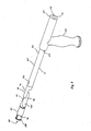
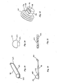
Figure 1 is an exploded view of a fastener assembly according to a first embodiment of the present invention prior to installation; -
Figures 2 and 3 are respective front and rear views of a collar component of the fastener shown inFigure 1 ; -
Figure 4 is a cross section view through A-A shown inFigure 2 ; -
Figure 5 is a side view looking in the same direction as inFigure 4 ; -
Figure 6 shows the component ofFigure 2 folded ready for installation; -
Figure 7 is a side view of a bolt component of the fastener shown inFigure 1 ; -
Figure 8 is a perspective view of a tool used for installing the assembly shown inFigure 1 ; -
Figures 9 and 10 are respectively a side view and plan view of the tool inFigure 8 ; -
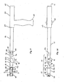
Figure 11 is a cut away view of the fastener assembly ofFigure 1 , shown in the process of installation using the installation tool shown inFigure 8 ; -
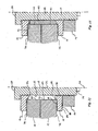
Figure 12 is a cross section through part of an assembled fastener assembly according to the first embodiment; -
Figure 13 is a cross section similar toFigure 12 but through part of an assembled fastener assembly according to a second embodiment of the invention; -
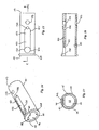
Figure 14 is an isometric view of a bolt-holding component of the tool shown inFigure 8 ; -
Figure 15 is a plan view of the component shown inFigure 14 ; -
Figure 16 is an axial cross section view through C-C shown inFigure 15 ; -
Figure 17 is a cross section view through D-D shown inFigure 9 ; -
Figure 18 is an isometric view of a retaining clip component of the tool shown inFigure 8 ; -
Figure 19 is a side view of the component shown inFigure 18 ; -
Figure 20 is a side view of a stud component of the retaining clip shown inFigure 18 ; -
Figure 21 is a cross section view of part of the retaining clip shown inFigure 18 prior to its assembly; and -
Figure 22 is a view of the end of the tail portion of an alternative configuration of a bolt component utilised in the invention. - Referring to
Figures 1 to 12 , afastener assembly 6 comprises afastener 8, anut 14 andwasher 16. Thefastener 8 consists of abolt portion 10 and around collar portion 12. The fastener joins twosteel plates 18 and 19 (together comprising a substrate) by passing throughholes Figure 12 shows a diametral half of the assembled and tensionedfastener 8 extending through theplates collar 12,washer 16 andnut 14 engaged. - The
bolt 10 has ashank 22 with, at oneend 24, anenlarged head 28 and, at theother end 26, atail 30 which carries athread 32 on a threadedportion 33 to suit thenut 14. Thehead 28 of thebolt 10 is a crown integrally formed with theshank 22. The head of thefastener 8 is thus the combination of thebolt head 28 and thecollar 12. On the end of itstail 30 the bolt carries anaxial protrusion 34 having aflat end face 37 and aperipheral surface 38. Theperipheral surface 38 has acurved portion 40 and aflat face 42. Thecurved portion 40 has a cylindrical form whose axis is coincident with themajor axis 36 of the bolt. The cylindrical form has a segment removed from its cylindrical shape so as to form theflat face 42 on theperipheral surface 38. - The
protrusion 34 thus has a non-circular cross-section. The cross section is D-shaped when viewed as a plane transverse to theaxis 36 of thebolt 12. Thecurved portion 40 of theperipheral surface 38 provides a circular curved edge 43 in cross section. Theflat face 42 on the periphery provides flat portion 44 on the cross-section. The maximum diameter of theprotrusion 34 is smaller than the root diameter of thebolt thread 32. - A short
circular hole 56 forms a recess in about the centre of theflat face 42. - As best seen in
Figures 2 to 6 , thecollar 12 comprises two half-collars backing strap 48. Thecollar 12 has acentral aperture 51 forming a bore surrounded by aboss 54 and an outwardly extending flange 55 to form a stepped front face 58 and a flat rear face 50. Each half-collar respective boss portions flange portions rear faces 50a and 50b. - The half-
collars strap 48 made from a strong adhesive tape which is tightly adhered to the rear faces 50a and 50b of respective half-collars. The half-collars narrow gap 45 which is bridged by thestrap 48. Thus theboss 54 and flange 55 are each discontinuous due to thegap 45 separating their halves. Thestrap 48 provides a pair ofhinges rear faces 50a and 50b abutting and the boss outwards. The portion of the strap bridging thegap 45 provides a length over which the strap can bend for hinging. - The
strap 48 is made of tape which has no significant resilience tending to open the collar out. In some less preferred embodiments thestrap 48 may have some resilient property, but not enough by itself to fully open out the collar to the position shown inFigure 5 . In other less preferred embodiments the strap does have sufficient resilience to fully open out the collar to the position shown inFigure 5 . - The
washer 16 has a shape the same as thecollar 12 but without the dividing gap nor backing strap. Acentral aperture 80 is surrounded by anaxially extending boss 82 and an outwardly extendingflange 84 to form a steppedfront face 86 and a flatrear face 88 on the washer. - The two half-
collars washer 16 in half, with thegap 45 being the width of the saw or laser cut. Alternatively the half-collars may be separately formed as identical components. - Referring to
Figures 8 to 11 and14 to 21 , the additional apparatus used to install thefastener assembly 6 comprises atool 60 having ahandle 62 mounted at right angles to, and part way along, anelongate shaft 64. Thehandle 62 is shown pointing downwards in the Figures. Theshaft 64 is generally cylindrical for most of its length, with a steppedbar portion 63 extending from itsrear end 65 to a non-cylindrical collar-supportingportion 66 of theshaft 64 and abolt engagement portion 67 of the shaft attached to the collar-supportingportion 66. - The
handle 62 is adapted to be held by hand. The collar-supportingportion 66 is thinned and is described in detail below. The bolt-engagement portion 67 includes a D-shapedsocket 68, on thefront end 70 of thetool 60, which engages with the D-shapedprotrusion 34 on the bolt. The bolt-engagement portion 67 also includes a manuallymoveable sleeve 76 and alatch 78 held captive by thesleeve 76. - The collar-supporting
portion 66 has aforward end 89 attached to the bolt-engagement portion 67 and arearward end 90 attached to the cylindrical portion of theshaft 64. The collar-supporting portion is thinned in two ways. Towards itsrearward end 90 it has a first thinnedportion 91 which is merely a flattened peripheral portion of the overall cross section of the shaft and has a curved upper face 92 and a flatlower face 94. The second thinnedportion 96, which is towards theforward end 89, is waisted. The second thinnedportion 96 is a thin flat portion positioned along a diameter of the shaft, and with its main faces 99 and 100 oriented vertically when thehandle 62 is pointed downwards, and atop edge 101 which is stepped inwards from the upper face 92 of the first thinned portion. - The first and second thinned
portions portion 93 of the collar-supportingportion 66 around the middle of the collar-supporting portion. Towards theleading end 134 of the collar-supportingportion 66, the collar-supporting portion is smoothly flared out over a taperedtransition region 135 by side faces 97 and 98 which extend from the diametrically aligned thinwaisted portion 96 to the full diameter of the shaft at theshoulder 137. The side faces 97 and 98 are flat in this preferred embodiment, but may be curved if desired. - In
Figure 11 , thefastener 8 is shown being installed through twosteel plates near side 72 of the plates.Holes plates fastener 8 will pass through those holes and clamp the plates firmly together. - To install the
fastener assembly 6, thenut 14,washer 16 andcollar 12 are first fed in that order onto theshaft 64 of the tool. The steppedfront face 86 of the washer faces the front face 58 of the collar. Theprotrusion 34 on thebolt 10 is then clipped into thesocket 68 and thesleeve 76 is adjusted to engage thelatch 78 with theprotrusion 34. and thereby prevent the protrusion from slipping out of the socket. That engagement of latch and protrusion is described later in this specification. Thebolt 10 is then fed head first through the alignedholes side 72 to thefar side 74 of the plates while at the same time manually positioning thecollar 12 on thecollar supporting portion 66 of theshaft 64. Thehead 28 of the bolt is a loose clearance fit through theholes tool 60 to support it on thefar side 74. - The collar is folded to hinge at 52 and 53 along the backing
strap 48 and is positioned on the collar-supporting portion so that thehinge 52 spans and is supported by the thinupper edge 101 of the diametrically alignedwaisted portion 96, the strap on the rear faces 50a and 50b lays substantially flat against side faces 99 and 100, and the end faces 102 and 104 of the half-collars and thehinge 53 are pressed into contact with thelower face 94 of the flattenedperipheral portion 91.Portions overlap portion 93. The folded collar is thereby aligned to be pushed through theholes collar supporting portion 66 is pushed through the holes. Theleading edge 106 of theperipheral portion 91 presses on theinside wall 108 of thebore 51 of the collar to push the collar through the holes. At this stage the collar is collapsed from its fully opened out condition to a configuration which has a total height of about half its full diameter. - When the
collar 12 emerges completely on thefar side 74 of the plates, thehinge 53 drops a little but the collar continues to hang from thehinge 52 with the rear faces 50a and 50b resting against or closely adjacent to the side faces 99 and 100 of thewaisted portion 96. Thehandle 62 is then pulled to draw thecollar supporting portion 66 of the tool back into the hole, thus causing theplate 18 to push the collar along the taperedtransition region 135 to thereby unfold thecollar 12. Rotation of the tool through 90° before pulling the handle back causes one of the half-collars transition region 135, and thus requiring less force pulling on the handle to fully open the collar. Pulling the handle back further draws theshank 22 of the bolt back into the hole, with thehead 28 pressing on thecollar 12 to fully open the collar and thereby assemble thefastener 8. - The half-
collars respective boss portion bore 51. These curved boss portions create adiscontinuous boss 54 on the collar when thefastener 8 is assembled in use. The thickness of each boss portion in the diametrical direction is slightly less than the clearance between theshank 22 of the bolt and thewall 23 of the hole. Thecollar 12 is thus able to take up the position shown inFigure 12 where theboss 54 serves to prevent the collar and the bolt from moving laterally relative to the hole. - The hinges 52 and 53 lie almost parallel to the
axis 36 as thecollar 12 is pushed through the holes while on the collar-supportingportion 66. Only the thickness of theperipheral portion 91 of the tool prevents completely parallel alignment of the hinges with the axis. The ability to nest the collar onto the tool with the collar's hinges aligned more parallel to theaxis 36 when compared with the prior art allows the diameter and/or thickness of the collar to be increased for any given diameter hole through the substrate. - The
washer 16 andnut 14 are then engaged with the thread 11 and tightened by hand. The bolt is then released from thesocket 68 and the nut is tightened to the desired tension using a spanner or power wrench as desired. - As shown most clearly in
Figure 12 thewasher 16 has itsboss 82 extending from thefront face 86 in contact with thesteel plate 19. The outside diameter of theboss 82 is slightly smaller than the diameter of thehole 21, so the boss fits neatly into the entry of thehole 21 and thus serves to positively locate theshank 22 central to the hole in the same manner as theboss 54 on thecollar 12 act in relation to thehole 20. - The
rear end 71 of theshaft 64 has a D-shapedsocket 75 formed therein which may be used to restrain thebolt 10 from turning while thenut 14 is being tightened. - The collar shown folded in
Figure 2 is oriented so that at the completion of installation thebacking strap 48 finishes being pressed between thebolt head 10 and the rear faces 50a and 50b of the half-collars. - The
tool 60 as described above is entirely of metal construction, although it may alternatively be constructed entirely from appropriately chosen engineering plastics material(s). Theportions socket joints respective pins diametrical holes engagement portion 67 andcollar supporting portion 66 may thus be conveniently replaced if worn or damaged. - The mechanism for fastening the bolt to the tool will now be described with particular reference to
Figures 11 and14 to 21 . Thebolt engagement portion 67 comprises atubular body portion 110 which has a bore 111 with a D-shaped cross-section and has a wall 116 of non-uniform thickness. Aleading end 112 of thebody portion 110 has an outwardly extendingflange 128 around its perimeter. Theinboard end 112 of theportion 110 is fastened by socket joint 141 to thecollar supporting portion 66. Thecurved face 114 of the bore 111 is on a portion of the wall 116 which is thinner than theportion 118 which forms the flat face 120 in the bore 111. - Into the thicker
walled portion 118 is cut from the outside of thetube 110 anelongate channel 122 having aflat bottom 123 and rounded ends 124 and 126. Theend 124 closest theleading end 112 of the tube has ahole 130 extending radially through thewall 118 into the bore 111, the diameter of thehole 130 being the same as the width of thechannel 122. The inboard end 126 of the channel, which is that end closest thehandle 62, has asmaller hole 132 extending from the channel radially into the bore 111. - Further towards the
inboard end 113 of thetubular body portion 110 is ahole 133 diametrically completely through the tube. Theleading end 134 of the collar-supportingportion 66 has aprotuberance 136 which neatly fits into the D-shaped bore at theinboard end 113 to form thesocket joint 141. Ashoulder 137 is formed on the collar-supporting portion where the collar-supporting portion expands from theprotuberance 136 to the circumferentially outer surface of theleading end 134. Acircular pin 138 forming an interference fit through thehole 133 and acorresponding hole 139 through theprotuberance 136 fastens the tubular body portion to the collar supporting portion. - A similar socket joint 161 joins the collar-supporting
portion 66 to themain body 61. However joint 161 is formed by a cylindrical protrusion on the collar-retaining portion engaging with asocket 162 on the main body portion and retained by apin 164 through adiametrical hole 163. Thepin 164 is selected to break, thus allowing the joint 161 to rotate, if the torque on the joint exceeds a value somewhat less than that required to damage thinnedportions - The retaining
clip 78 shown inFigures 18 and 19 forms a latch in the bolt-engagement portion 67. Thebody 142 of thelatch 78 is an elongate flat strip of metal having rounded ends 144 and 146 termed the latching end and the retained end respectively. On thelatching end 144 is a hemispherically-endedstud 148, while at the retained end 146 of thelatch 78, the strip metal of itsbody 142 is narrowed and turned at right angles to extend as anarrow tab 150 in the same direction as thestud 148. The stud has ahemispherical end 151 rising from a shortcylindrical portion 152. The length of thecylindrical portion 152 is about the same as the length of thehole 130. Thebody 142 of the latch has ahole 153 therethrough into which atail 154 of thestud 148 is expanded in order to fasten thestud 148 to thebody 142. - In use, the
latch 78 is located with itsbody 142 resting in thechannel 122, itsstud 148 extending inwards into thelarger hole 130 and thetab 150 extending inwards into thesmaller hole 132. While thetab 150 is not long enough to project past the flat face 120 into the bore 111, thestud 148 acts as a moveable member which is long enough to extend into the bore when depressed but nevertheless short enough to withdraw from the bore. - The thin-walled
tubular sleeve 76 is held captive on the outside of thetubular body portion 110 such that the sleeve is free to slide backwards and forwards along the length of the tubular body portion and also slide around it. The sleeve is held captive by the outwardly extendingflange 128 at theleading end 112 and, at theinboard end 113 by theshoulder 137 on the collar-supporting portion. - The thickness of the
body 142 of the latch is such that when thesleeve 76 slides forwards to theleading end 112, thestud 148 is held down at maximum projection in thehole 130 and thehemispherical end 151 protrudes from theflat wall 118 inside the socket and engages into therecess 56 in the bolt. However when the sleeve slides back to the inboard end 113 (the position shown inFigure 11 ), the latch may tilt lengthways so that thestud 138 retracts through theflat wall 118 of the socket, thus disengaging from thehole 56, and theprotrusion 34 is then free to slide out of thesocket 68. - Even when the
sleeve 76 is withdrawn to its position back against the collar supporting portion, as seen inFigures 8 to 11 , the latch cannot be removed from thechannel 122 because the sleeve still covers the retained end 146 of the latch so that thetab 150 is held captive (although with some limited movement) within thehole 132. - Thus, in order to attach the
tool 60 to thebolt 10, thesleeve 76 is slid back towards the handle of the tool and theprotrusion 34 on the bolt is slipped into thesocket 68. This forms aninterface 121 between the flat faces 42 and 120 and between the curved faces 40 and 114. Thesleeve 76 is then slid forward so depressing the stud across theinterface 121 and into therecess 56. Thebody 142 of the latch is prevented from moving radially outwards by thesleeve 76. The stud mechanically locks the bolt to the socket. The bolt at this stage cannot be pulled from the socket without something breaking or irreversibly distorting. This constitutes a positive location of the head of the stud into the recess and does not depend upon any spring loading mechanism. - Typical nominal dimensions for a fastener used with 30 mm diameter holes in the
steel plates - diameter of bolt crown :
- 29 mm
- diameter of bolt shank:
- 20 mm
- inside diameter of collar and washer:
- 21 mm
- outside diameter of collar and washer:
- 42 mm
- thickness of flange on collar and washer:
- 6 mm
- depth of bore in collar and flange:
- 8 mm (including height of boss)
- height of boss rising from flange:
- 2 mm
-
Figure 13 shows a second embodiment of the invention which is preferred for joins under high shear loading. Asleeve 162 is fed onto theshaft 64 of the tool between the collar and the washer and is pressed along over theshank 22 of the bolt into theholes - The
sleeve 162 is sized so that the sum of its length plus the heights of the bosses on the collar and washer is a little shorter than the total length through theplates nut 14. The inside and outside diameters of thesleeve 162 are selected to be a loose (but not sloppy) sliding fit to thebolt 10 and theholes sleeve 162 thus neatly fills the annular gap between the bolt and the walls of theholes sleeve 162 into the holes. - A sleeve applied to the example fastener dimensioned above would have a nominal internal diameter of 20mm and outside diameter of 29mm. For joints under high shear, this is equivalent to having a fastener with a 29mm shank through the 30mm hole. For a cost-effective greater increase in shear strength of the fastening, a higher strength steel may be used for the sleeve than is used for the bolt. If there is little or no shear component to the loading, then the sleeve may be omitted from the assembly if required as shown in
Figure 12 . - While less preferred versions of the invention may utilise a spring loaded mechanism for urging the stud into the recess, the positive fastening provided by the above described embodiment is preferred.
- A preferred alterative configuration of the recess in the protrusion is shown on the
bolt 170 inFigure 22 . Thebolt 170 works with thesame tool 60 as described above. However whereas the recess previously described is acircular hole 56, the recess inFigure 22 is aslot 172 formed across the flattenedface 174. Such a slot can be formed in the same operation as that which machines the flattenedface 174 and thus a further drilling operation to make the hole is not required. - It is to be understood that various alterations, modifications and/or additions may be introduced into the constructions and arrangements of parts previously described without departing from the spirit or ambit of the invention. For example whereas the
slot 172 shown inFigure 22 has a rectangular cross section with aflat bottom 176 andflat side walls 178, the slot may alternatively have a cross section which is semicircular, V-shaped, or any other shape which provides a positive interlock with a correspondingly shaped mating stud on thelatch 78. - Also, in some alternative embodiments of the invention, the
nut 14 andwasher 16 are combined into a single item such that the nut has a boss corresponding toboss 82 which in use engages into thehole 21 as the nut is tightened. - Also, in some alternative embodiments of the invention, the
collar supporting portion 66 is welded to (or otherwise integrally formed with) the leading end of themain body portion 61 of the tool rather than having pinnedsocket joint 161. Similarly the collar-supportingportion 66 may be welded to (or otherwise integrally formed with) the bolt-engagingportion 67 rather than having the pinnedsocket joint 141. - Also, in some less preferred embodiments of the invention the
protrusion 34 and engaging socket have simple cylindrical forms so that, unless the stud is engaged into the recess, the protrusion is free to rotate in the socket. - Throughout this specification, unless the context requires otherwise, the word "comprise", and variations such as "comprises" and "comprising", will be understood to imply the inclusion of a stated feature or group of features but not the exclusion of any other feature or group of features.
Claims (14)
- A method of installing a threaded fastener (8) from one side (72) of a hole (20,21) through a substrate (18,19), said fastener comprising:(a) a bolt (10) having:(i) an enlarged head portion (28) at one end,(ii) a threaded tail portion (33) at the end opposite said head, and(iii) a tool engagement portion (34) extending from said threaded tail portion (33), and(b) a washer-like collar (12) having an aperture (51) therethrough,said method comprising:(a) engaging said tool engagement portion (34) with a bolt engagement portion (67) of a tool (60),(b) passing said bolt completely through said hole head first from said one side, being the near side (72) of said hole, to the far side (74) of said hole,(c) supporting said bolt (10) on said far side (74) of said hole by way of said tool which is extending through said hole,(d) passing said collar (12) completely through said hole (20,21) while supporting said collar with said tool (60) extending through said aperture (51) and through said hole, said collar being collapsed with portions (46,47) of said collar lying on respective opposite sides of said tool as said collar is being passed through said hole;(e) causing said bolt (10) and said collar (12) to assemble to form said threaded fastener (8) having a head larger than said hole on said far side of the hole, a shank (22) within said hole, and portion of said threaded tail on the near side of said hole;(f) engaging a nut (14) with said threaded tail portion (33) on said near side (72) and rotating said nut to tighten said fastener; and(g) detaching said tool (60) from said fastener (8);characterised in that said bolt engagement portion (67) and said tool engagement portion (34) engage along an interface (38), and separation of said bolt engagement portion and said tool engagement portion is prevented by a moveable member (78) which engages said bolt engagement portion and said tool engagement portion across said interface.
- A method according to claim 1 characterized in that said tool engagement portion (34) comprises a protrusion (34) extending from said threaded tail portion (33), said bolt engagement portion comprises a socket (68), and said protrusion and said socket engage in a sliding fit along an interface (38) aligned in an axial direction relative to said bolt.
- A method according to claim 2 characterized in that said protrusion (34) includes a recess (56) and said bolt engagement portion includes a moveable member (148) which engages into said recess to thereby prevent withdrawal of said protrusion (34) from within said socket (68).
- A method according to any one of the previous claims characterized in that said moveable member (78) is manually activated towards said engagement into the recess (56) by means of manually sliding an outer sleeve (76) on said bolt engagement portion (67).
- A method according to claim 4 characterized in that said moveable member (78) comprises a stud (148) on a flattened strip (142).
- A method according to claim 5 characterized in that, when said moveable member (148) is activated towards said engagement, said outer sleeve (76) prevents said strip (142) from moving radially outwards relative to the threaded tail portion (33).
- A method according to any one of claims 2 to 6 characterized in that said protrusion (34) has a non-circular cross section so as to prevent rotation of said protrusion in said socket (68).
- A method according to claim 7 characterized in that said non-circular cross section has a straight portion, such that said protrusion has a flattened face (42) on its periphery (38).
- A method according to claim 7 characterized in that said non-circular cross section is D-shaped, the rounded portion (40) of which is circular having a centre which lies on the axis (36) of said threaded tail portion, such that said protrusion (34) has a cylindrical face (40) and a flattened face (42) on its periphery (38).
- A method according to any one of the previous claims characterized in that said tool (60) has a handle (62), a shaft (64) attached to the handle, and said bolt engagement portion (67) affixed to one end of said shaft (64), said shaft including on respective portions of its length:- a flattened peripheral portion (91), and- a flattened diametrically aligned portion (96) located between said flattened peripheral portion (91) and said bolt engagement portion (67) and extending towards said handle (62) to partly overlap with said flattened peripheral portion (91),
and wherein as said collar (12) is passed through said hole (20,21), said collar is supported at a first folded portion (52) by said diametrically aligned portion (96). - A method according to claim 10 characterized in that, as said collar (12) is passed through said hole (20,21), said collar (12) is folded with portions (46,47) of said collar lying on respective opposite sides of said diametrically aligned portion (96), said collar spans said overlap (93) of said flattened peripheral portion and said diametrically aligned portion, and a second folded portion (53) of said collar abuts said flattened peripheral portion (91).
- A bolt (10) comprising(i) an enlarged head portion (28) at one end,(ii) a threaded tail portion (33) at the end opposite said head,(iii) a major axis (36) running the length of said bolt, and(iv) a protrusion (34) extending from said threaded tail portion (33), said protrusion having a non-circular cross section transverse to said axis and having formed therein a recess (56),
characterized in that said non-circular cross section is D-shaped, the rounded portion of which is circular having a centre which lies on said major axis (36) such that said protrusion has on the periphery thereof a cylindrical face (40) and a flattened face (42) in which said recess (56) is formed, said recess being adapted in use to receive a moveable member (148) on a tool (60) to thereby prevent withdrawal of said protrusion from the tool. - A threaded fastener characterized in that it comprises the combination of a bolt (10) according to claim 12 and a washer-like collar (12), said collar comprising two rigid halves (46,47) joined by flexibly hinge portions (52,53).
- A threaded fastener according to claim 13 characterized in that the collar (12), when in a flat, unfolded configuration, has an outer dimension greater than the diameter of the smallest aperture through which the bolt head (28) may pass, and said collar defining an aperture (51) through which said threaded tail portion (33) but not said bolt head (28) may pass.
Priority Applications (1)
| Application Number | Priority Date | Filing Date | Title |
|---|---|---|---|
| EP06014835.0A EP1880800B1 (en) | 2006-07-17 | 2006-07-17 | Threaded fastener and method of installation |
Applications Claiming Priority (1)
| Application Number | Priority Date | Filing Date | Title |
|---|---|---|---|
| EP06014835.0A EP1880800B1 (en) | 2006-07-17 | 2006-07-17 | Threaded fastener and method of installation |
Publications (2)
| Publication Number | Publication Date |
|---|---|
| EP1880800A1 EP1880800A1 (en) | 2008-01-23 |
| EP1880800B1 true EP1880800B1 (en) | 2015-11-18 |
Family
ID=37451023
Family Applications (1)
| Application Number | Title | Priority Date | Filing Date |
|---|---|---|---|
| EP06014835.0A Not-in-force EP1880800B1 (en) | 2006-07-17 | 2006-07-17 | Threaded fastener and method of installation |
Country Status (1)
| Country | Link |
|---|---|
| EP (1) | EP1880800B1 (en) |
Families Citing this family (6)
| Publication number | Priority date | Publication date | Assignee | Title |
|---|---|---|---|---|
| US9145908B2 (en) | 2011-12-16 | 2015-09-29 | Ev Ip Lp | Blind fastener |
| JP2015218902A (en) * | 2014-05-21 | 2015-12-07 | 正雄 佐藤 | Two-hole type bolt |
| CN108131373A (en) * | 2018-02-08 | 2018-06-08 | 张丽 | A kind of application method of short-tail staking fastening kit, dismantling device and dismantling device |
| CN110125596A (en) * | 2019-06-28 | 2019-08-16 | 云南力帆骏马车辆有限公司 | Welding tooling location structure and localization method |
| CN110900519B (en) * | 2019-11-27 | 2021-10-08 | 同济大学 | Mounting tool for sectional type split connection unilateral bolt fastener |
| CN111365347B (en) * | 2020-03-16 | 2022-02-15 | 中国北方车辆研究所 | A flat-head bolt with hole for displacement detection between relative motion part |
Family Cites Families (2)
| Publication number | Priority date | Publication date | Assignee | Title |
|---|---|---|---|---|
| AUPP618398A0 (en) * | 1998-09-25 | 1998-10-22 | Ajax Technology Centre Pty Ltd | Threaded fasteners |
| US20040208722A1 (en) * | 2003-04-17 | 2004-10-21 | Pop-In Pop-Out, Inc. | Fastener adapted for use with a structural member |
-
2006
- 2006-07-17 EP EP06014835.0A patent/EP1880800B1/en not_active Not-in-force
Also Published As
| Publication number | Publication date |
|---|---|
| EP1880800A1 (en) | 2008-01-23 |
Similar Documents
| Publication | Publication Date | Title |
|---|---|---|
| US7373709B2 (en) | Method of installing a blind threaded fastener | |
| US20230037370A1 (en) | Anchor assembly for fastener | |
| EP1880800B1 (en) | Threaded fastener and method of installation | |
| EP1861628B1 (en) | T-bolt clamp quick attach latch | |
| CA2472858C (en) | Coupling assembly with retention mechanism | |
| US6568894B2 (en) | Fastener devices, such as lock-pins | |
| US7226261B1 (en) | Toggle assembly | |
| JP2005517876A (en) | Expandable collet anchor device, its components and methods for making and using the same | |
| US11053968B1 (en) | Blind bolt | |
| US9038360B1 (en) | Shackle assembly with locking pin | |
| US5219254A (en) | Expandable fastener and locking means therefor | |
| US8966874B2 (en) | Shackle assembly with locking pin | |
| US10087964B2 (en) | Fastener for securing together two panels | |
| NZ511290A (en) | Blind bolting | |
| US9714674B1 (en) | Fastener device | |
| CA2552448C (en) | Improvements in relation to blind bolting | |
| JP2009063070A (en) | Split nut | |
| CA2592203A1 (en) | Pre-positionable toggle anchor system | |
| JPH0854009A (en) | Expansion bolt | |
| US11421722B1 (en) | Blind bolt and tool combination | |
| WO1992009813A1 (en) | Fastener insert device | |
| AU766347B2 (en) | Blind bolting | |
| WO2014099130A1 (en) | Shackle assembly with locking pin |
Legal Events
| Date | Code | Title | Description |
|---|---|---|---|
| PUAI | Public reference made under article 153(3) epc to a published international application that has entered the european phase |
Free format text: ORIGINAL CODE: 0009012 |
|
| AK | Designated contracting states |
Kind code of ref document: A1 Designated state(s): AT BE BG CH CY CZ DE DK EE ES FI FR GB GR HU IE IS IT LI LT LU LV MC NL PL PT RO SE SI SK TR |
|
| AX | Request for extension of the european patent |
Extension state: AL BA HR MK YU |
|
| 17P | Request for examination filed |
Effective date: 20080709 |
|
| 17Q | First examination report despatched |
Effective date: 20080808 |
|
| AKX | Designation fees paid |
Designated state(s): AT BE BG CH CY CZ DE DK EE ES FI FR GB GR HU IE IS IT LI LT LU LV MC NL PL PT RO SE SI SK TR |
|
| GRAP | Despatch of communication of intention to grant a patent |
Free format text: ORIGINAL CODE: EPIDOSNIGR1 |
|
| GRAS | Grant fee paid |
Free format text: ORIGINAL CODE: EPIDOSNIGR3 |
|
| GRAA | (expected) grant |
Free format text: ORIGINAL CODE: 0009210 |
|
| AK | Designated contracting states |
Kind code of ref document: B1 Designated state(s): AT BE BG CH CY CZ DE DK EE ES FI FR GB GR HU IE IS IT LI LT LU LV MC NL PL PT RO SE SI SK TR |
|
| REG | Reference to a national code |
Ref country code: GB Ref legal event code: FG4D |
|
| REG | Reference to a national code |
Ref country code: CH Ref legal event code: EP |
|
| REG | Reference to a national code |
Ref country code: AT Ref legal event code: REF Ref document number: 761288 Country of ref document: AT Kind code of ref document: T Effective date: 20151215 |
|
| REG | Reference to a national code |
Ref country code: IE Ref legal event code: FG4D |
|
| REG | Reference to a national code |
Ref country code: DE Ref legal event code: R096 Ref document number: 602006047310 Country of ref document: DE |
|
| REG | Reference to a national code |
Ref country code: NL Ref legal event code: MP Effective date: 20160218 |
|
| REG | Reference to a national code |
Ref country code: LT Ref legal event code: MG4D |
|
| REG | Reference to a national code |
Ref country code: AT Ref legal event code: MK05 Ref document number: 761288 Country of ref document: AT Kind code of ref document: T Effective date: 20151118 |
|
| PG25 | Lapsed in a contracting state [announced via postgrant information from national office to epo] |
Ref country code: IS Free format text: LAPSE BECAUSE OF FAILURE TO SUBMIT A TRANSLATION OF THE DESCRIPTION OR TO PAY THE FEE WITHIN THE PRESCRIBED TIME-LIMIT Effective date: 20160318 Ref country code: IT Free format text: LAPSE BECAUSE OF FAILURE TO SUBMIT A TRANSLATION OF THE DESCRIPTION OR TO PAY THE FEE WITHIN THE PRESCRIBED TIME-LIMIT Effective date: 20151118 Ref country code: NL Free format text: LAPSE BECAUSE OF FAILURE TO SUBMIT A TRANSLATION OF THE DESCRIPTION OR TO PAY THE FEE WITHIN THE PRESCRIBED TIME-LIMIT Effective date: 20151118 Ref country code: ES Free format text: LAPSE BECAUSE OF FAILURE TO SUBMIT A TRANSLATION OF THE DESCRIPTION OR TO PAY THE FEE WITHIN THE PRESCRIBED TIME-LIMIT Effective date: 20151118 Ref country code: LT Free format text: LAPSE BECAUSE OF FAILURE TO SUBMIT A TRANSLATION OF THE DESCRIPTION OR TO PAY THE FEE WITHIN THE PRESCRIBED TIME-LIMIT Effective date: 20151118 |
|
| REG | Reference to a national code |
Ref country code: DE Ref legal event code: R082 Ref document number: 602006047310 Country of ref document: DE Representative=s name: HERNANDEZ, YORCK, DIPL.-ING., DE |
|
| PG25 | Lapsed in a contracting state [announced via postgrant information from national office to epo] |
Ref country code: PL Free format text: LAPSE BECAUSE OF FAILURE TO SUBMIT A TRANSLATION OF THE DESCRIPTION OR TO PAY THE FEE WITHIN THE PRESCRIBED TIME-LIMIT Effective date: 20151118 Ref country code: PT Free format text: LAPSE BECAUSE OF FAILURE TO SUBMIT A TRANSLATION OF THE DESCRIPTION OR TO PAY THE FEE WITHIN THE PRESCRIBED TIME-LIMIT Effective date: 20160318 Ref country code: GR Free format text: LAPSE BECAUSE OF FAILURE TO SUBMIT A TRANSLATION OF THE DESCRIPTION OR TO PAY THE FEE WITHIN THE PRESCRIBED TIME-LIMIT Effective date: 20160219 Ref country code: AT Free format text: LAPSE BECAUSE OF FAILURE TO SUBMIT A TRANSLATION OF THE DESCRIPTION OR TO PAY THE FEE WITHIN THE PRESCRIBED TIME-LIMIT Effective date: 20151118 Ref country code: FI Free format text: LAPSE BECAUSE OF FAILURE TO SUBMIT A TRANSLATION OF THE DESCRIPTION OR TO PAY THE FEE WITHIN THE PRESCRIBED TIME-LIMIT Effective date: 20151118 Ref country code: SE Free format text: LAPSE BECAUSE OF FAILURE TO SUBMIT A TRANSLATION OF THE DESCRIPTION OR TO PAY THE FEE WITHIN THE PRESCRIBED TIME-LIMIT Effective date: 20151118 Ref country code: LV Free format text: LAPSE BECAUSE OF FAILURE TO SUBMIT A TRANSLATION OF THE DESCRIPTION OR TO PAY THE FEE WITHIN THE PRESCRIBED TIME-LIMIT Effective date: 20151118 |
|
| REG | Reference to a national code |
Ref country code: FR Ref legal event code: PLFP Year of fee payment: 11 |
|
| PG25 | Lapsed in a contracting state [announced via postgrant information from national office to epo] |
Ref country code: CZ Free format text: LAPSE BECAUSE OF FAILURE TO SUBMIT A TRANSLATION OF THE DESCRIPTION OR TO PAY THE FEE WITHIN THE PRESCRIBED TIME-LIMIT Effective date: 20151118 |
|
| REG | Reference to a national code |
Ref country code: DE Ref legal event code: R097 Ref document number: 602006047310 Country of ref document: DE |
|
| PG25 | Lapsed in a contracting state [announced via postgrant information from national office to epo] |
Ref country code: EE Free format text: LAPSE BECAUSE OF FAILURE TO SUBMIT A TRANSLATION OF THE DESCRIPTION OR TO PAY THE FEE WITHIN THE PRESCRIBED TIME-LIMIT Effective date: 20151118 Ref country code: SK Free format text: LAPSE BECAUSE OF FAILURE TO SUBMIT A TRANSLATION OF THE DESCRIPTION OR TO PAY THE FEE WITHIN THE PRESCRIBED TIME-LIMIT Effective date: 20151118 Ref country code: RO Free format text: LAPSE BECAUSE OF FAILURE TO SUBMIT A TRANSLATION OF THE DESCRIPTION OR TO PAY THE FEE WITHIN THE PRESCRIBED TIME-LIMIT Effective date: 20151118 Ref country code: DK Free format text: LAPSE BECAUSE OF FAILURE TO SUBMIT A TRANSLATION OF THE DESCRIPTION OR TO PAY THE FEE WITHIN THE PRESCRIBED TIME-LIMIT Effective date: 20151118 |
|
| PLBE | No opposition filed within time limit |
Free format text: ORIGINAL CODE: 0009261 |
|
| STAA | Information on the status of an ep patent application or granted ep patent |
Free format text: STATUS: NO OPPOSITION FILED WITHIN TIME LIMIT |
|
| 26N | No opposition filed |
Effective date: 20160819 |
|
| PG25 | Lapsed in a contracting state [announced via postgrant information from national office to epo] |
Ref country code: SI Free format text: LAPSE BECAUSE OF FAILURE TO SUBMIT A TRANSLATION OF THE DESCRIPTION OR TO PAY THE FEE WITHIN THE PRESCRIBED TIME-LIMIT Effective date: 20151118 |
|
| PG25 | Lapsed in a contracting state [announced via postgrant information from national office to epo] |
Ref country code: BE Free format text: LAPSE BECAUSE OF FAILURE TO SUBMIT A TRANSLATION OF THE DESCRIPTION OR TO PAY THE FEE WITHIN THE PRESCRIBED TIME-LIMIT Effective date: 20151118 |
|
| REG | Reference to a national code |
Ref country code: CH Ref legal event code: PL |
|
| PG25 | Lapsed in a contracting state [announced via postgrant information from national office to epo] |
Ref country code: MC Free format text: LAPSE BECAUSE OF FAILURE TO SUBMIT A TRANSLATION OF THE DESCRIPTION OR TO PAY THE FEE WITHIN THE PRESCRIBED TIME-LIMIT Effective date: 20151118 |
|
| PG25 | Lapsed in a contracting state [announced via postgrant information from national office to epo] |
Ref country code: LI Free format text: LAPSE BECAUSE OF NON-PAYMENT OF DUE FEES Effective date: 20160731 Ref country code: CH Free format text: LAPSE BECAUSE OF NON-PAYMENT OF DUE FEES Effective date: 20160731 |
|
| REG | Reference to a national code |
Ref country code: IE Ref legal event code: MM4A |
|
| REG | Reference to a national code |
Ref country code: FR Ref legal event code: PLFP Year of fee payment: 12 |
|
| PG25 | Lapsed in a contracting state [announced via postgrant information from national office to epo] |
Ref country code: IE Free format text: LAPSE BECAUSE OF NON-PAYMENT OF DUE FEES Effective date: 20160717 |
|
| PG25 | Lapsed in a contracting state [announced via postgrant information from national office to epo] |
Ref country code: LU Free format text: LAPSE BECAUSE OF NON-PAYMENT OF DUE FEES Effective date: 20160717 |
|
| PG25 | Lapsed in a contracting state [announced via postgrant information from national office to epo] |
Ref country code: HU Free format text: LAPSE BECAUSE OF FAILURE TO SUBMIT A TRANSLATION OF THE DESCRIPTION OR TO PAY THE FEE WITHIN THE PRESCRIBED TIME-LIMIT; INVALID AB INITIO Effective date: 20060717 Ref country code: CY Free format text: LAPSE BECAUSE OF FAILURE TO SUBMIT A TRANSLATION OF THE DESCRIPTION OR TO PAY THE FEE WITHIN THE PRESCRIBED TIME-LIMIT Effective date: 20151118 |
|
| PG25 | Lapsed in a contracting state [announced via postgrant information from national office to epo] |
Ref country code: TR Free format text: LAPSE BECAUSE OF FAILURE TO SUBMIT A TRANSLATION OF THE DESCRIPTION OR TO PAY THE FEE WITHIN THE PRESCRIBED TIME-LIMIT Effective date: 20151118 |
|
| REG | Reference to a national code |
Ref country code: FR Ref legal event code: PLFP Year of fee payment: 13 |
|
| PG25 | Lapsed in a contracting state [announced via postgrant information from national office to epo] |
Ref country code: BG Free format text: LAPSE BECAUSE OF FAILURE TO SUBMIT A TRANSLATION OF THE DESCRIPTION OR TO PAY THE FEE WITHIN THE PRESCRIBED TIME-LIMIT Effective date: 20151118 |
|
| PGFP | Annual fee paid to national office [announced via postgrant information from national office to epo] |
Ref country code: DE Payment date: 20190719 Year of fee payment: 14 Ref country code: FR Payment date: 20190719 Year of fee payment: 14 |
|
| PGFP | Annual fee paid to national office [announced via postgrant information from national office to epo] |
Ref country code: GB Payment date: 20190719 Year of fee payment: 14 |
|
| REG | Reference to a national code |
Ref country code: DE Ref legal event code: R119 Ref document number: 602006047310 Country of ref document: DE |
|
| GBPC | Gb: european patent ceased through non-payment of renewal fee |
Effective date: 20200717 |
|
| PG25 | Lapsed in a contracting state [announced via postgrant information from national office to epo] |
Ref country code: FR Free format text: LAPSE BECAUSE OF NON-PAYMENT OF DUE FEES Effective date: 20200731 Ref country code: GB Free format text: LAPSE BECAUSE OF NON-PAYMENT OF DUE FEES Effective date: 20200717 |
|
| PG25 | Lapsed in a contracting state [announced via postgrant information from national office to epo] |
Ref country code: DE Free format text: LAPSE BECAUSE OF NON-PAYMENT OF DUE FEES Effective date: 20210202 |