EP1879331B1 - Kommunikationsnetzwerksystem und Fehlerüberprüfungsverfahren - Google Patents
Kommunikationsnetzwerksystem und Fehlerüberprüfungsverfahren Download PDFInfo
- Publication number
- EP1879331B1 EP1879331B1 EP07111901A EP07111901A EP1879331B1 EP 1879331 B1 EP1879331 B1 EP 1879331B1 EP 07111901 A EP07111901 A EP 07111901A EP 07111901 A EP07111901 A EP 07111901A EP 1879331 B1 EP1879331 B1 EP 1879331B1
- Authority
- EP
- European Patent Office
- Prior art keywords
- slot
- frame
- information concerning
- violation
- boundary
- Prior art date
- Legal status (The legal status is an assumption and is not a legal conclusion. Google has not performed a legal analysis and makes no representation as to the accuracy of the status listed.)
- Not-in-force
Links
Images


Classifications
-
- H—ELECTRICITY
- H04—ELECTRIC COMMUNICATION TECHNIQUE
- H04L—TRANSMISSION OF DIGITAL INFORMATION, e.g. TELEGRAPHIC COMMUNICATION
- H04L12/00—Data switching networks
- H04L12/28—Data switching networks characterised by path configuration, e.g. LAN [Local Area Networks] or WAN [Wide Area Networks]
- H04L12/40—Bus networks
- H04L12/40006—Architecture of a communication node
- H04L12/40013—Details regarding a bus controller
-
- H—ELECTRICITY
- H04—ELECTRIC COMMUNICATION TECHNIQUE
- H04L—TRANSMISSION OF DIGITAL INFORMATION, e.g. TELEGRAPHIC COMMUNICATION
- H04L12/00—Data switching networks
- H04L12/28—Data switching networks characterised by path configuration, e.g. LAN [Local Area Networks] or WAN [Wide Area Networks]
- H04L12/40—Bus networks
- H04L12/403—Bus networks with centralised control, e.g. polling
- H04L12/4035—Bus networks with centralised control, e.g. polling in which slots of a TDMA packet structure are assigned based on a contention resolution carried out at a master unit
-
- H—ELECTRICITY
- H04—ELECTRIC COMMUNICATION TECHNIQUE
- H04L—TRANSMISSION OF DIGITAL INFORMATION, e.g. TELEGRAPHIC COMMUNICATION
- H04L12/00—Data switching networks
- H04L12/28—Data switching networks characterised by path configuration, e.g. LAN [Local Area Networks] or WAN [Wide Area Networks]
- H04L12/40—Bus networks
- H04L12/407—Bus networks with decentralised control
-
- H—ELECTRICITY
- H04—ELECTRIC COMMUNICATION TECHNIQUE
- H04L—TRANSMISSION OF DIGITAL INFORMATION, e.g. TELEGRAPHIC COMMUNICATION
- H04L12/00—Data switching networks
- H04L12/28—Data switching networks characterised by path configuration, e.g. LAN [Local Area Networks] or WAN [Wide Area Networks]
- H04L12/40—Bus networks
- H04L2012/40208—Bus networks characterized by the use of a particular bus standard
- H04L2012/40241—Flexray
Definitions
- the invention relates in general to a time-division-multiplexing communication network system and an error verification method. Aspects of the invention relate to a system, to a method and to a vehicle.
- a communication protocol called "FlexRay” (trademark of Daimler Chrysler AG) is known as a type of protocol for a communication network system installed in a vehicle. FlexRay realizes a communication speed of a maximum of approximately 10 Mbps (megabits per second) while ensuring high reliability. FlexRay has attracted attention as an important technology for practicing electronic control (X-by-wire) of a portion related to vehicle running.
- a time trigger method is employed as a data transfer method, and frame transmission timing and frame receiving timing of each of nodes on a network are scheduled beforehand.
- so-called "communication cycles" are used.
- One communication cycle defines a static segment in which each slot that is a time interval for transmitting a frame has a fixed length, and a dynamic segment in which each slot has a variable length.
- each node on the network recognizes timing of each slot assigned to the node in the static segment and dynamic segment in each communication cycle in accordance with a global time that is common time recognition in the network, and that node transmits a frame to be transmitted to a different node in the slot.
- the node recognizes timing of each slot assigned for transmitting a frame to be received by the node and receives a frame transmitted from the different node in the slot.
- the node acquires reception status information representing a frame reception state in the slot, and, on the basis of the reception status information, checks whether to normally receive the frame.
- the different node After the different node acquires the reception status information representing the boundary violation, the different node discards the received frame without allowing an application of the different node to use data of received frame. In other words, both frames in which the boundary violation occurs are discarded. Details of the reception status information in FlexRay are described in " FlexRay Communication System Protocol Specification, Version 2.1, Revision A", December 2005, pages 204-207 .
- the above reception status information representing the occurrence of a boundary violation error is output such that the signal component is detected at the slot boundary.
- the reception status information is similarly acquired by both slots.
- both frames in which the boundary violation occurs are discarded. Therefore, although a receiving node receives a correct frame, the receiving node cannot use data of the received frame in an application of the receiving node, thus causing a decrease in efficiency.
- a communication network system for performing time-division-multiplexing communication in which a frame is received in a reception slot to be received by a node in a communication cycle including a data transfer period and an idle period
- the communication network system comprising a network and a plurality of nodes coupled to the network; wherein at least one node of the plurality of nodes includes a reception-status-information acquiring unit configured to acquire boundary violation information concerning a reception slot to be received by the node and at least one adjacent slot adjacent to the reception slot and to acquire frame state information concerning each of the reception slot and the at least one adjacent slot, an error-factor verifying unit configured to verify an error factor of the reception slot based on the boundary violation information and the frame state information and a frame-use determining unit configured to determine whether data of a frame received in the reception slot is usable based on a result of verification by the error-factor verifying unit and configured to use the frame for control when the data of the frame is usable.
- the error-factor verifying unit is configured to specify a slot boundary at which a boundary violation occurs based on content of the boundary violation information concerning each of the adjacent slots when the boundary violation information concerning the reception slot represents occurrence of the boundary violation and the error-factor verifying unit is configured to specify a factor causing the boundary violation based on the frame state information concerning the reception slot and the frame state information concerning the reception slot and one of the adjacent slots across a slot in which the boundary violation occurs.
- the frame-use determining unit is configured to conclude that the frame is usable when, in verification by the error-factor verifying unit, the boundary violation information concerning the reception slot represents violation, the boundary violation information concerning a preceding slot adjacent to the reception slot represents violation, the frame state information concerning the reception slot represents normality, and the frame state information concerning the preceding slot represents abnormality.
- the frame-use determining unit is configured to conclude that the frame is usable when, in verification by the error-factor verifying unit, the boundary violation information concerning the reception slot represents violation, the boundary violation information concerning a succeeding slot adjacent to the reception slot represents violation, the frame state information concerning the reception slot represents normality, and the frame state information concerning the succeeding slot represents abnormality.
- the frame-use determining unit is configured to conclude that the frame is usable when, in verification by the error-factor verifying unit, the boundary violation information concerning the reception slot represents violation, the boundary violation information concerning a preceding slot adjacent to the reception slot represents violation, the frame state information concerning the reception slot represents normality, and the frame state information concerning the preceding slot adjacent to the reception slot represents normality.
- the frame-use determining unit is configured to conclude that the frame is usable when, in verification by the error-factor verifying unit, the boundary violation information concerning the reception slot represents violation, the boundary violation information concerning a succeeding slot adjacent to the reception slot represents violation, the frame state information concerning the reception slot represents normality, and the frame state information concerning the succeeding slot adjacent to the reception slot represents normality.
- the frame state information is at least one of information indicating whether a valid frame has been received, information indicating whether a grammatically correct frame has been received, and information indicating whether a frame correct in content has been received.
- each of the plurality of nodes further comprises a synchronization-shift-node determining unit configured to, based on a result of verification by the error-factor verifying unit, determine whether a node in which a synchronization shift occurs is detected, the node being included in sender nodes of frames and a synchronization-shift reporting unit configured to, when the synchronization-shift-node determining unit determines that the node in which the synchronization shift occurs is detected, reports occurrence of the synchronization shift to the node in which the synchronization shift occurs.
- a vehicle including the communication network system as set out in any of the preceding paragraphs.
- a communication network system for performing time-division-multiplexing communication in which a frame is received in a reception slot to be received by a node in a communication cycle including a data transfer period and an idle period
- the communication network system comprising a network and a plurality of nodes connected to the network, wherein at least one node of the plurality of nodes comprises a reception-status-information acquiring unit that acquires boundary violation information concerning each of three slots consisting of a reception slot to be received by the node, and preceding and succeeding slots adjacent to the reception slot, and frame state information concerning each of the reception slot and the preceding and succeeding slots, an error-factor verifying unit that verifies an error factor of the reception slot based on the boundary violation information and the frame state information and a frame-use determining unit configured to, based on a result of verification by the error-factor verifying unit, determines whether data of the frame received in the reception slot is usable, and configured to use the frame for control when the
- a communication network system for performing time-division-multiplexing communication in which a frame is received in a reception slot to be received by a node in a communication cycle including a data transfer period and an idle period
- the communication network system comprising a network and a plurality of nodes coupled to the network; wherein at least one node of the plurality of nodes includes means for acquiring boundary violation information concerning a reception slot to be received by the node and at least one adjacent slot adjacent to the reception slot and to acquire frame state information concerning each of the reception slot and the at least one adjacent slot, means for verifying an error factor of the reception slot based on the boundary violation information and the frame state information and means for determining whether data of a frame received in the reception slot is usable based on a result of verification by the verifying means and for using the frame for control when the data of the frame is usable.
- a method for determining use of a received frame in at least one node among a plurality of nodes connected to a network comprising verifying an error factor of the reception slot based on acquisition of boundary violation information and frame state information concerning a reception slot to be received by the node and at least one adjacent slot adjacent to the reception slot and determining whether data of a frame received in the reception slot is usable.
- the method may comprise specifying a slot boundary at which a boundary violation occurs based on content of the boundary violation information concerning each of the adjacent slots when the boundary violation information concerning the reception slot represents occurrence of the boundary violation and specifying a factor causing the boundary violation based on the frame state information concerning the reception slot and the frame state information concerning the reception slot and one of the adjacent slots across a slot in which the boundary violation occurs.
- the method may comprise concluding that the frame is usable when the boundary violation information concerning the reception slot represents violation, the boundary violation information concerning a preceding slot adjacent to the reception slot represents violation, the frame state information concerning the reception slot represents normality, and the frame state information concerning the preceding slot represents abnormality.
- the method may comprise concluding that the frame is usable when the boundary violation information concerning the reception slot represents violation, the boundary violation information concerning a succeeding slot adjacent to the reception slot represents violation, the frame state information concerning the reception slot represents normality, and the frame state information concerning the succeeding slot represents abnormality.
- the method may comprise concluding that the frame is usable when the boundary violation information concerning the reception slot represents violation, the boundary violation information concerning a preceding slot adjacent to the reception slot represents violation, the frame state information concerning the reception slot represents normality, and the frame state information concerning the preceding slot adjacent to the reception slot represents normality.
- the method may comprise concluding that the frame is usable when the boundary violation information concerning the reception slot represents violation, the boundary violation information concerning a succeeding slot adjacent to the reception slot represents violation, the frame state information concerning the reception slot represents normality, and the frame state information concerning the succeeding slot adjacent to the reception slot represents normality.
- the frame state information is at least one of information indicating whether a valid frame has been received, information indicating whether a grammatically correct frame has been received, and information indicating whether a frame correct in content has been received.
- the method may comprise determining whether a node in which a synchronization shift occurs is detected and reporting occurrence of the synchronization shift to the node in which the synchronization shift occurs when the node in which the synchronization shift occurs is detected.
- a communication network system for performing time-division-multiplexing communication in which a frame is received in a reception slot to be received by a node in a communication cycle including a data transfer period and an idle period may comprise a network and a plurality of nodes coupled to the network.
- At least one node of the plurality of nodes includes a reception-status-information acquiring unit configured to acquire boundary violation information concerning a reception slot to be received by the node and at least one adjacent slot adjacent to the reception slot and to acquire frame state information concerning each of the reception slot and the at least one adjacent slot; an error-factor verifying unit configured to verify an error factor of the reception slot based on the boundary violation information and the frame state information; and a frame-use determining unit configured to determine whether data of a frame received in the reception slot is usable based on a result of verification by the error-factor verifying unit and configured to use the frame for control when the data of the frame is usable.
- the present invention provides a communication network system for realizing efficient communication by accurately identifying an error factor represented by reception status information and appropriately responding to the error factor.
- the communication network system can include acquiring boundary violation information and frame state information concerning each of a reception slot and adjacent slots by each of nodes on a network, verifying an error factor of the reception slot on the basis of the boundary violation information and frame state information concerning each of the slots, determining whether or not data of a frame received in the reception slot is usable on the basis of the result of verification of the error factor, and, if it is determined that the data of the received frame is usable, using the received frame for control.
- a plurality of electronic control units (ECUs) for controlling an in-vehicle electric system have communication functions, and the ECUs are connected as nodes on a network to a FlexRay bus.
- the ECUs share information by communicating with one another in accordance with a FlexRay protocol, whereby the communication network system realizes various types of control based on cooperative operations of the ECUs.
- ECUs generally comprise microcontrollers or the like.
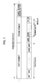
- FIG. 1 shows an outline of a data transfer mechanism in FlexRay employed as the communication protocol in such a communication network system.
- the FlexRay data transfer method is a time trigger method in which each node on the network transmits frames with transmitting timing scheduled beforehand. Data transfer between the nodes is performed by using, as each unit, a communication cycle that is repeated while the communication network system is operating.
- the communication cycle includes four segments, a static segment, a dynamic segment, a symbol window and a network idle time.
- the static segment is a period in which data transfer is performed with a constant frame size and includes a plurality of static slots.
- One static slot is a time interval (band) in which one frame is transmitted in one static segment. The times of all the static slots are equal, and the lengths of frames transmitted in the slots are also equal.
- each node on the network performs communication only in accordance with a predetermined schedule.
- the dynamic segment is a period in which data transfer is performed with a variable frame size and includes a plurality of dynamic slots.
- One dynamic slot is a time interval in which one frame is transmitted in the dynamic segment, and the length of the dynamic slot can be changed on the basis of a transmission request of each node on the network.
- the node on the network can perform communication in accordance with priority.
- the symbol window is a segment that is used in modes such as a network startup mode and a wakeup mode.
- the network idle time is a segment that is used for purposes such as error correction and synchronization correction value calculation.
- the dynamic segment and symbol window in the above communication cycle are set as options and may not be necessary depending on the configuration and use of the communication network system.
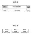
- FIG. 2 shows an outline of a FlexRay frame format.
- a FlexRay frame includes three segments, a header segment (5 bytes), a payload segment (0 to 254 bytes) and a trailer segment (3 bytes).
- the header segment contains header information concerning data to be transmitted, and the payload segment contains the data itself.
- the trailer segment has a function of checking whether the entire frame has an error, and the trailer contains the result of performing a cyclic redundancy check (CRC) on the header segment and the payload segment.
- CRC cyclic redundancy check
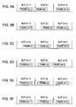
- each node on the network recognizes, in the static segment and dynamic segment of the above communication cycle, slots assigned as frame transmission periods of the node.
- Each node transmits, in the slots, frames each having the above format and including application data of the node.
- the sizes of the slots can be set to lengths in which the frames to be transmitted can sufficiently be accommodated.
- the node on the network transmits the frames in the slots with sufficient slot boundaries provided between the frames. In other words, in each slot in the communication cycle idle periods are provided before and after a frame to be transmitted in the slot, and a slot boundary between an interframe idle period and an adjacent slot is in an idle state having no signal component.
- each node on the network recognizes, in the static segment and dynamic segment in the above communication cycle, slots (hereinafter referred to as "reception slots") assigned for transmitting frames to be received by the node.
- Each node receives, in these reception slots, frames transmitted by a different node.
- each node acquires reception status information representing an in-slot frame reception state, specifically the pieces of reception status information shown in FIG. 4 .
- the node Based on the pieces of reception status information, the node performs diagnosis about whether frames have normally been received from the different node. Among the pieces of reception status information shown in FIG.
- “ValidFrame” indicates whether or not a valid frame has been received
- “SyntaxError” indicates whether or not a grammatically correct frame has been received
- “ContentError” indicates whether or not a correct content frame has been received. All are pieces of information representing in-slot frame normality. In the following description, the above pieces of reception status information are generically referred to as “pieces of frame state information.”
- “Bviolation” indicates whether or not a boundary violation has occurred at one slot boundary and is a piece of information that is set to "violation” when a signal component is detected at the slot boundary. This piece of information is hereinafter referred to as "boundary violation information.”
- each node on the network receives a frame in a reception slot, and a piece of frame state information obtained by the reception slot represents "abnormal reception," the node can determine that an error occurs in the frame itself. Accordingly, the node discards data of the received frame without allowing an application of the node to use the data.
- the six cases shown in FIGS. 5A to 5F are possible as factors of the "violation" where among the pieces of reception status information obtained when the node receives a frame in the reception slot, the boundary violation information represents "violation.” It is not possible to identify which of the cases in FIGS. 5A to 5F occurs only on the basis of the boundary violation information concerning the reception slot.
- FIG. 5A shows a case in which, when a node receives frame(m) in reception slot(n), frame(m) is transmitted crossing a slot boundary between reception slot(n) and a preceding slot(n-1) adjacent to reception slot(n). This is due to a cause such as a synchronization shift of a sender node of frame(m).
- a communication-bus voltage change (signal component) is detected at this slot boundary, whereby the boundary violation information is set to represent "violation.”
- FIG. 5B is a case in which, frame(m) is transmitted crossing a slot boundary between reception slot(n) and succeeding slot(n+1) adjacent to reception slot(n) when a node receives frame(m) in reception slot(n). This is also due to a cause such as a synchronization shift of a sender node of frame(m). In this case, a communication-bus voltage change (signal component) is detected at this slot boundary, whereby the boundary violation information is set to represent "violation.”
- FIG. 5C illustrates a case in which, frame(m-1) is transmitted crossing a slot boundary between reception slot(n) and preceding slot(n-1) adjacent to reception slot(n) when a node receives frame(m) in reception slot(n). This is due to a case such as a synchronization shift of a sender node of frame(m-1) in preceding slot(n-1) adjacent to reception slot(n). Then, a communication-bus voltage change (signal component) is detected at this slot boundary, whereby the boundary violation information is set to represent "violation.”
- FIG. 5D shows a case wherein, when a node receives frame(m) in reception slot(n), frame(m+1) is transmitted crossing a slot boundary between reception slot(n) and succeeding slot(n+1) adjacent to reception slot(n). This is due to a cause such as a synchronization shift of a sender node of frame(m+1) in succeeding slot(n+1) adjacent to reception slot(n). Then a communication-bus voltage change (signal component) is detected at this slot boundary, whereby the boundary violation information is set to represent "violation.”
- FIG. 5E illustrates a case wherein when a node receives frame(m) in reception slot(n), momentary noise is generated at a slot boundary between reception slot(n) and preceding slot(n-1) adjacent to reception slot(n).
- a communication-bus voltage change (signal component) is detected at this slot boundary, whereby the boundary violation information is set to represent "violation.”
- FIG. 5F illustrates a case wherein when a node receives frame(m) in reception slot(n), momentary noise is generated at a slot boundary between reception slot(n) and succeeding slot(n+1) adjacent to reception slot(n).
- a communication-bus voltage change (signal component) is generated at this slot boundary, whereby the boundary violation information is set to represent "violation.”
- the factors in FIGS. 5A and 5B are errors of the received frames themselves, and data items of the received frames are not used by applications.
- the factors in FIGS. 5C to 5F are malfunctions of different frames transmitted in adjacent slots and the effects of noise. Accordingly, the factors in FIGS. 5C to 5F are not malfunctions of the received frames themselves.
- the data items of the received frames can be used by the nodes.
- each of the above-described cases in FIGS. 5A to 5F cannot be identified only on the basis of the boundary violation information concerning the reception slot.
- the boundary violation information that represents "violation" is acquired on the basis of one of the factors in FIGS. 5C to 5F , data of a frame received by a node is discarded without being used by an application of the node. This causes a decrease in efficiency.
- each node on the network receives not only a frame in a reception slot but also frames in slots adjacent to the frame in the reception slot. That is, the node can acquire frames in three slots including the reception slot and two slots adjacent to the reception slot.
- the node can acquire frames in three slots including the reception slot and two slots adjacent to the reception slot.
- by verifying whether an error occurs in the reception slot and verifying an error factor on the basis of the reception status information concerning the three slots for example, when the boundary violation information in the reception slot represents "violation," it can be identified which of the above-described cases in FIGS. 5A to 5F causes the factor of the "violation.” In this manner, appropriate responses can be achieved. Specifically, for each of the cases in FIGS. 5A and 5B data of the received frame is discarded, and for each of the cases in FIGS. 5C to 5F data of a frame received by a node is used by an application of the node.
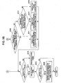
- FIGS. 6 and 7 a first example of a node included in the communication network system according to an embodiment of the invention is described with reference to FIGS. 6 and 7 .
- a node 10 is an ECU having an internal configuration of hardware including a host central processing unit (CPU) 11, a communication controller 12 and a bus driver 13.
- the host CPU 11 is a controller for controlling operations of the entirety of the node 10
- the communication controller 12 is a controller for controlling communication of the node 10.
- the bus driver 13 is used for signal conversion between a physical signal and a logical signal between a communication bus 100 and the communication controller 12.
- the node 10 is connected to other nodes through the communication bus 100.
- the node 10 When the node 10 receives frames sent from a different node to the communication bus 100, the node 10 performs frame receiving processing under the control of the communication controller 12.
- This frame receiving processing occurs not only in a reception slot containing a frame (hereinafter referred to as a "receiving frame") to be received by the node 10, but also occurs in preceding and succeeding slots adjacent to the reception slot, whereby reception status information (boundary violation information and frame state information) of each of the three slots, that is, the preceding slot, the reception slot and the succeeding slot, is acquired.
- the host CPU 11 verifies whether an error occurs in the reception slot and verifies a factor of the error. Based on the result of the verification, the host CPU 11 can determine whether data of the received frame is to be used by an application of the node 10.
- the node 10 has a boundary violation verification function 14, an error portion specifying function 15, an error identifying function 16 and a frame-use determination function 17 as functions of the host CPU 11 realized by software, can be implemented in hardware, or can be implemented in a combination of hardware and software.
- the boundary violation verification function 14 verifies whether boundary violation occurs at one of slot boundaries before and after the reception slot.
- the boundary violation verification function 14 verifies boundary violation of the reception slot on the basis of boundary violation information that is acquired when the communication controller 12 performs frame receiving processing in the reception slot.
- the error portion specifying function 15 is used to specify at which slot boundary the boundary violation occurs when the boundary violation verification function 14 determines that the boundary violation occurs at one of slot boundaries before and after the reception slot. Based on the boundary violation information acquired when the communication controller 12 performs receiving processing on a frame in the preceding slot (hereinafter referred to as a "preceding frame"), and the boundary violation information acquired when the communication controller 12 performs receiving processing on a frame in the succeeding frame (hereinafter referred to as a "succeeding frame”), the error portion specifying function 15 specifies a slot boundary at which the boundary violation occurs.
- the error identifying function 16 identifies an error factor of the boundary violation that occurs at the slot boundary specified by the error portion specifying function 15. Error factors of the boundary violation include boundary exceeding of the received frame, boundary exceeding of the preceding frame, boundary exceeding of the succeeding frame and noise generation.
- the error portion specifying function 15 specifies a slot boundary between the reception slot and the preceding slot as the slot boundary at which the boundary violation occurs
- the error identifying function 16 identifies which of the above-described cases is the error factor of the boundary violation based on the frame state information acquired when the communication controller 12 performs receiving processing on the preceding frame in the preceding slot and the frame state information acquired when the communication controller 12 performs receiving processing on the receiving frame in the reception slot.
- the error identifying function 16 identifies which of the above-described cases is the error factor of the boundary violation based on the frame state information acquired when the communication controller 12 performs receiving processing on the receiving frame in the reception slot and the frame state information acquired when the communication controller 12 performs receiving processing on the succeeding frame in the succeeding slot.
- the frame-use determination function 17 determines whether or not the data of the receiving frame can be used by an application of the node 10 based on the error factor of the boundary violation identified by the error identifying function 16.
- the frame-use determination function 17 determines that data of the receiving frame can be used by the application of the node 10 since the identified error factor is not a malfunction of the receiving frame itself.
- the frame-use determination function 17 determines that the data of the receiving frame cannot be used by the application of the node 10 since an error occurs or is likely to occur in the receiving frame itself.
- FIGS. 7A and 7B are flowcharts showing a sequential process that executes each function of the host CPU 11 in the node 10 in this embodiment. Processing of the host CPU 11 is described in accordance with the flowcharts shown in FIGS. 7A and 7B and is repeatedly executed by the host CPU 11 whenever the communication controller 12 performs receiving processing on the receiving, preceding and succeeding frames, and the reception status information (boundary violation information and frame state information) concerning the reception, preceding and succeeding slots is acquired.
- the host CPU 11 confirms whether the boundary violation information concerning the reception slot represents "violation" in step S101. If the boundary violation information concerning the reception slot represents "no violation,” the host CPU 11 sets an error type to "no error (type A)" in step S102.
- the error type is information identifying an error factor of the boundary violation of the reception slot.
- step S101 the host CPU 11 confirms whether the boundary violation information concerning the preceding slot represents "violation" in step S103. If it is confirmed in step S103 that the boundary violation information concerning the reception slot represents "violation,” the boundary violation occurs at the slot boundary between the reception slot and the preceding slot. Thus, in step S104 the host CPU 11 confirms whether the frame state information concerning the reception slot represents "abnormal reception.” If the frame state information concerning the reception slot represents "abnormal reception,” the host CPU 11 sets the error type to "boundary exceeding of the receiving frame (type B)" in step S105.
- the host CPU 11 confirms whether the frame state information of the preceding slot represents "abnormal reception” in step S106. If it is confirmed that the frame state information of the preceding slot represents "abnormal reception” in step S106, the host CPU 11 sets the error type to "boundary exceeding of the preceding frame (type C)" in step S107. Alternately, if it is confirmed that the frame state information of the preceding slot does not represent "abnormal reception” in step S106, the host CPU 11 sets the error type to "noise generation (type D)" in step S108.
- step S109 the host CPU 11 confirms whether the boundary violation information concerning the succeeding slot represents "violation” in step S109. If it is confirmed that the boundary violation information concerning the succeeding slot represents "violation” in step S109, it is determined that the boundary violation occurs at the slot boundary between the reception slot and the succeeding slot. Thus, in step S110, the host CPU 11 confirms whether the frame state information concerning the reception slot represents "abnormal reception.” If the frame state information concerning the reception slot represents "abnormal reception” in step S110, the host CPU 11 sets the error type to "boundary exceeding of the receiving frame (type B)" in step S111.
- step S110 the host CPU 11 confirms whether the frame state information of the succeeding slot represents "abnormal reception” in step S112. In step S112, if it is confirmed that the frame state information of the succeeding slot represents "abnormal reception,” the host CPU 11 sets the error type to "boundary exceeding of the succeeding slot (type E)" in step S113. Alternately, if it is confirmed that the frame state information of the succeeding slot does not represent "abnormal reception” in step S112, the host CPU 11 sets the error type to "noise generation (type D)" in step S114.
- step S109 if it is confirmed that the boundary violation information concerning the succeeding slot does not represent "violation," the slot boundary at which the boundary violation occurs cannot be specified. For example, it is possible that the boundary violation occurs due to a different factor such as malfunction of the communication controller 12. In this case, the host CPU 11 sets the error type to "different error (type F)" in step S115.
- the host CPU 11 After the error type is set in any of steps S115, S105, S107, S108, S102, S1 11, S113 and S114, the host CPU 11 confirms the error type in step S116.
- the error type is one of "no error (type A)," “boundary exceeding of the preceding frame (type C),” “noise generation (type D)” and "boundary exceeding of the succeeding frame (type E),” the host CPU 11 determines that the receiving frame itself has no malfunction in step S117 and allows the application of the node 10 to use the data of the receiving frame.
- the host CPU 11 determines that an error occurs or is likely to occur in the receiving frame itself and discards the data of the receiving frame without allowing the application of the node 10 to use the data.
- a node 20 has a synchronization shift determining function 18 and a synchronization shift reporting function 19 in addition to the boundary violation verification function 14, the error portion specifying function 15, the error identifying function 16 and the frame-use determination function 17.
- These functions can be implemented in hardware, software run by the host CPU 11 or a combination of hardware and software. Other components are common to those of the node 10 in the first example and are accordingly not described again.
- the result of identifying performed by the error identifying function 16 is used not only in the frame-use determination function 17 but also in the synchronization shift determining function 18.
- the synchronization shift determining function 18 determines, based on an error factor of boundary violation identified by the error identifying function 16, whether a node in which a synchronization shift occurs is detected (that is, the node being included in sender nodes of frames). When the error factor of the boundary violation identified by the error identifying function 16 is boundary exceeding of the receiving frame, the synchronization shift determining function 18 determines that a synchronization shift occurs in the sender node of the receiving frame.
- the synchronization shift determining function 18 determines that a synchronization shift occurs in a sender node of the preceding frame.
- the synchronization shift determining function 18 determines that a synchronization shift occurs in a sender node of the succeeding frame.
- the synchronization shift reporting function 19 reports the occurrence of the synchronization shift to the sender node.
- a synchronization-shift-reporting frame for reporting the occurrence of a synchronization shift is prepared.
- the synchronization shift determining function 18 specifies a node in which a synchronization shift occurs, the synchronization-shift-reporting frame is transmitted in a predetermined slot as a slot in which the node performs receiving processing.
- a technique for reporting a synchronization shift to a sender node of a frame in which boundary exceeding occurs is not limited to the above-described technique, but various techniques can be used.
- FIGS. 9A and 9B are flowcharts showing a sequential process that is executed by each function of the host CPU 11 in the node 20.
- the process shown in FIG. 9 can be repeatedly executed by the host CPU 11 whenever the communication controller 12 performs receiving processing on the receiving, and preceding and succeeding frames, and the reception status information (boundary violation information and frame state information) concerning the reception, preceding and succeeding slots is acquired.
- the reception status information concerning the reception, preceding and succeeding slots is first acquired.
- steps S201 to S218 shown in FIGS. 9A and 9B the error factor of the boundary violation concerning the reception slot is identified, and, depending on the error type, it is determined whether the data of the receiving frame is to be used by an application of the node 20.
- Steps S201 to S218 shown in FIGS. 9A and 9B are not fully described since steps S201 to S218 are identical to steps S101 to S118 shown in FIGS. 7A and 7B .
- step S219 the host CPU 11 confirms the error type again.
- the error type is "boundary exceeding of the receiving frame (type B)," “boundary exceeding of the preceding frame (type C),” or “boundary exceeding of the succeeding frame (type E),” the host CPU 11 determines that a synchronization shift occurs in the sender node of the frame in which the boundary exceeding occurs and transmits the synchronization-shift-reporting frame to the sender node in step S220,.
- each node on a network receives not only a frame in a reception slot but also frames in adjacent slots before and after the frame in the reception slot.
- the node can acquire reception status information concerning three slots, that is, the reception slot and two adjacent slots before and after the reception slot. Based on the reception status information concerning the three slots, it is verified whether an error occurs in the reception slot and an error factor is verified. Therefore, according to the communication network system, the node on the network can appropriately determine whether an error occurs in the reception slot and the error factor.
- an appropriate response depending on the error factor can be performed such as if a receiving frame of a node has no malfunction, data of the receiving frame is used by an application of the node. Alternately, if it is determined that the receiving frame has a malfunction, the data is discarded. Thus, efficient communication can be realized.
- each node on the network verifies an error factor of boundary violation in a reception slot, whereby a sender node of a frame in which a synchronization shift occurs can be identified.
- the occurrence of the synchronization shift can be reported to the sender node of the frame in which the synchronization shift occurs.
Landscapes
- Engineering & Computer Science (AREA)
- Computer Networks & Wireless Communication (AREA)
- Signal Processing (AREA)
- Small-Scale Networks (AREA)
Claims (11)
- Kommunikationsnetzwerksystem zum Durchführen einer Zeitmultiplex-Kommunikation, bei dem ein Datenblock in einem Empfangsslot empfangen wird, der von einem Knoten in einem Kommunikationszyklus, umfassend einen Datenübertragungszeitraum und einen Stillstandszeitraum, empfangen werden soll, wobei das System umfasst:ein Netzwerk; undeine Vielzahl von Knoten (10), die mit dem Netzwerk verbunden sind; wobei zumindest ein Knoten (10) der Vielzahl von Knoten (10) umfasst:eine Empfangsstatusinformations-Erhalteinrichtung (14) zum Erhalten von Grenzverletzungsinformationen bezüglich eines Empfangsslots, der von dem Knoten (10) und zumindest eines Nachbarslots angrenzend an den Empfangsslot empfangen werden soll und um Datenblock-Zustandsinformationen bezüglich jedes Empfangsslots und des zumindest einen Nachbarslots zu erhalten;eine Fehlerfaktor-Prüfeinrichtung (16) zum Prüfen eines Fehlerfaktors des Empfangsslots auf der Grundlage der Grenzverletzungsinformationen und der Datenblock-Zustandsinformationen; undeine Datenblock-Benutzungsbestimmungseinrichtung (17) zum Bestimmen, auf der Grundlage der Prüfung durch die Fehlerfaktor-Prüfeinrichtung (16), ob Daten eines Datenblocks, der im Empfangsslot empfangen wurde, verwendbar sind, und ausgelegt, den Datenblock zur Steuerung zu verwenden, wenn die Daten des Datenblocks verwendbar sind.
- System nach Anspruch 1, wobei die Fehlerfaktor-Prüfeinrichtung (16) angeordnet ist, um, auf der Grundlage des Inhalts der Grenzverletzungsinformationen jedes Nachbarslots, eine Slotbegrenzung festzulegen, an der eine Grenzverletzung auftritt, wenn die Grenzverletzungsinformationen bezüglich des Empfangsslots ein Auftreten der Grenzverletzung darstellen, und wobei die Fehlerfaktor-Prüfeinrichtung (16) angeordnet ist, auf der Grundlage der Datenblock-Zustandsinformationen bezüglich des Empfangsslots und der Datenblock-Zustandsinformationen bezüglich des Empfangsslots und eines Nachbarblocks über einem Slot, in dem die Grenzverletzung auftritt, einen Faktor festzulegen, der die Grenzverletzung verursacht.
- System nach Anspruch 1 oder Anspruch 2, wobei die Datenblock-Benutzungsbestimmungseinrichtung (17) angeordnet ist, um zu folgern, dass der Datenblock nutzbar ist, wenn, bestätigt durch die Fehlerfaktor-Prüfeinrichtung (16):die Grenzverletzungsinformation bezüglich des Empfangsslots eine Verletzung darstellt, die Grenzverletzungsinformation bezüglich eines vorherigen Slots angrenzend an den Empfangsslot eine Verletzung darstellt, die Datenblock-Zustandsinformation bezüglich des Empfangsslots Normalität darstellt und die Datenblock-Zustandsinformation bezüglich des vorherigen Slots Anormalität darstellt;die Grenzverletzungsinformation bezüglich des Empfangsslots eine Verletzung darstellt, die Grenzverletzungsinformation bezüglich eines nachfolgenden Slots angrenzend an den Empfangsslot eine Verletzung darstellt, die Datenblock-Zustandsinformation bezüglich des Empfangsslots Normalität darstellt und die Datenblock-Zustandsinformation bezüglich des nachfolgenden Slots Anormalität darstellt;die Grenzverletzungsinformation bezüglich des Empfangsslots eine Verletzung darstellt, die Grenzverletzungsinformation bezüglich eines vorherigen Slots angrenzend an den Empfangsslot eine Verletzung darstellt, die Datenblock-Zustandsinformation bezüglich des Empfangsslots Normalität darstellt und die Datenblock-Zustandsinformation bezüglich des vorherigen Slots angrenzend an den Empfangsslot Normalität darstellt; und/oderdie Grenzverletzungsinformation bezüglich des Empfangsslots eine Verletzung darstellt, die Grenzverletzungsinformation bezüglich eines nachfolgenden Slots angrenzend an den Empfangsslot eine Verletzung darstellt, die Datenblock-Zustandsinformation bezüglich des Empfangsslots Normalität darstellt und die Datenblock-Zustandsinformation bezüglich des nachfolgenden Slots angrenzend an den Empfangsslot Normalität darstellt.
- System nach irgendeinem vorstehenden Anspruch, wobei die Datenblock-Zustandsinformation zumindest eine von Informationen, die angeben, ob ein gültiger Datenblock empfangen wurde, von Informationen, die angeben, ob ein grammatikalisch korrekter Datenblock empfangen wurde, und von Informationen, die angeben, ob ein Datenblock mit korrektem Inhalt empfangen wurde, ist.
- System nach irgendeinem vorstehenden Anspruch, wobei jeder der Vielzahl von Knoten (10) umfasst:eine Synchronisierungsverschiebungsknoten-Bestimmungseinrichtung (18) zum Bestimmen, auf der Grundlage eines Ergebnisses der Prüfung durch die Fehlerfaktor-Prüfeinrichtung (16), ob ein Knoten (10), in dem eine Synchronisierungsverschiebung auftritt, erfasst wird, wobei der Knoten (10) in Sendeknoten der Datenübertragungsblöcke enthalten ist; undeine Synchronisierungsverschiebungs-Mitteilungseinrichtung (19) zum Mitteilen des Auftretens der Synchronisierungsverschiebung zu dem Knoten (10), in dem die Synchronisierungsverschiebung auftritt, wenn die Synchronisierungsverschiebungskonten-Bestimmungseinrichtung (18) bestimmt, dass der Knoten (10), in dem die Synchronisierungsverschiebung auftritt, erfasst wurde.
- Verfahren zum Bestimmen einer Verwendung eines empfangenen Datenblocks in zumindest einem Knoten (10) aus einer Vielzahl von Knoten (10), die mit einem Netzwerk verbunden sind, wobei das Verfahren umfasst:Prüfen eines Fehlerfaktors des Empfangsslots auf der Grundlage eines Erhalts von Grenzverletzungsinformationen und Datenblock-Zustandsinformationen bezüglich eines Empfangsslots, der von dem Knoten empfangen werden soll, und zumindest eines Nachbarslots angrenzend an den Empfangsslot; undBestimmen, ob Daten eines im Empfangsslot empfangenen Datenblocks nutzbar sind.
- Verfahren nach Anspruch 6, umfassend:Festlegen einer Slotgrenze, an der eine Grenzverletzung auftritt, auf der Grundlage des Inhalts der Grenzverletzungsinformationen bezüglich jedes Nachbarslots, wenn die Grenzverletzungsinformationen bezüglich des Empfangsslots ein Auftreten der Grenzverletzung darstellen; undFestlegen eines Faktors, der die Grenzverletzung verursacht, auf der Grundlage der Datenblock-Zustandsinformationen bezüglich des Empfangsslots und der Datenblock-Zustandsinformationen bezüglich des Empfangsslots und eines Nachbarslots über einem Slot, in dem die Grenzverletzung auftritt.
- Verfahren nach Anspruch 6 oder Anspruch 7, umfassend ein Folgern, dass der Datenblock nutzbar ist, wenn:die Grenzverletzungsinformation bezüglich des Empfangsslots eine Verletzung darstellt, die Grenzverletzungsinformation bezüglich eines vorherigen Slots angrenzend an den Empfangsslot eine Verletzung darstellt, die Datenblock-Zustandsinformation bezüglich des Empfangsslots Normalität darstellt und die Datenblock-Zustandsinformation bezüglich des vorherigen Slots Anormalität darstellt;die Grenzverletzungsinformation bezüglich des Empfangsslots eine Verletzung darstellt, die Grenzverletzungsinformation bezüglich eines nachfolgenden Slots angrenzend an den Empfangsslot eine Verletzung darstellt, die Datenblock-Zustandsinformation bezüglich des Empfangsslots Normalität darstellt und die Datenblock-Zustandsinformation bezüglich des nachfolgenden Slots Anormalität darstellt;die Grenzverletzungsinformation bezüglich des Empfangsslots eine Verletzung darstellt, die Grenzverletzungsinformation bezüglich eines vorherigen Slots angrenzend an den Empfangsslot eine Verletzung darstellt, die Datenblock-Zustandsinformation bezüglich des Empfangsslots Normalität darstellt und die Datenblock-Zustandsinformation bezüglich des vorherigen Slots angrenzend an den Empfangsslot Normalität darstellt; und/oderdie Grenzverletzungsinformation bezüglich des Empfangsslots eine Verletzung darstellt, die Grenzverletzungsinformation bezüglich eines nachfolgenden Slots angrenzend an den Empfangsslot eine Verletzung darstellt, die Datenblock-Zustandsinformation bezüglich des Empfangsslots Normalität darstellt und die Datenblock-Zustandsinformation bezüglich des nachfolgenden Slots angrenzend an den Empfangsslot Normalität darstellt.
- Verfahren nach einem der Ansprüche 6 bis 8, wobei die Datenblock-Zustandsinformation zumindest eine von Informationen, die angeben, ob ein gültiger Datenblock empfangen wurde, von Informationen, die angeben, ob ein grammatikalisch korrekter Datenblock empfangen wurde, und von Informationen, die angeben, ob ein Datenblock mit korrektem Inhalt empfangen wurde, ist.
- Verfahren nach einem der Ansprüche 6 bis 9, umfassend Bestimmen, ob ein Knoten, in dem eine Synchronisierungsverschiebung auftritt, erfasst wird, und Mitteilen des Auftretens der Synchronisierungsverschiebung zu dem Knoten (10), in dem die Synchronisierungsverschiebung auftritt, wenn der Knoten (10), in dem die Synchronisierungsverschiebung auftritt, erfasst wurde.
- Fahrzeug mit einem System nach einem der Ansprüche 1 bis 5.
Applications Claiming Priority (1)
| Application Number | Priority Date | Filing Date | Title |
|---|---|---|---|
| JP2006189678A JP4807171B2 (ja) | 2006-07-10 | 2006-07-10 | 通信ネットワークシステム及びエラー検証方法 |
Publications (2)
| Publication Number | Publication Date |
|---|---|
| EP1879331A1 EP1879331A1 (de) | 2008-01-16 |
| EP1879331B1 true EP1879331B1 (de) | 2011-01-19 |
Family
ID=38626653
Family Applications (1)
| Application Number | Title | Priority Date | Filing Date |
|---|---|---|---|
| EP07111901A Not-in-force EP1879331B1 (de) | 2006-07-10 | 2007-07-06 | Kommunikationsnetzwerksystem und Fehlerüberprüfungsverfahren |
Country Status (5)
| Country | Link |
|---|---|
| US (1) | US8488621B2 (de) |
| EP (1) | EP1879331B1 (de) |
| JP (1) | JP4807171B2 (de) |
| CN (1) | CN101106438B (de) |
| DE (1) | DE602007012022D1 (de) |
Families Citing this family (8)
| Publication number | Priority date | Publication date | Assignee | Title |
|---|---|---|---|---|
| JP2009100426A (ja) * | 2007-10-19 | 2009-05-07 | Nec Corp | 信号監視装置、通信システム、信号監視方法、および信号監視装置のプログラム |
| CN102171953B (zh) * | 2008-10-06 | 2015-11-25 | 三菱电机株式会社 | 数据中继系统以及工作时刻分配方法 |
| US8885614B2 (en) * | 2009-12-17 | 2014-11-11 | Qualcomm Incorporated | Avoidance of synchronization oscillation in TD-SCDMA uplink synchronization |
| JP5267598B2 (ja) * | 2011-02-25 | 2013-08-21 | トヨタ自動車株式会社 | 車両制御装置のデータ書き換え支援システム及びデータ書き換え支援方法 |
| JP5919205B2 (ja) * | 2013-01-28 | 2016-05-18 | 日立オートモティブシステムズ株式会社 | ネットワーク装置およびデータ送受信システム |
| CN106936677B (zh) | 2015-12-31 | 2020-06-26 | 华为技术有限公司 | 一种模块化ups系统及功率设备的数据传输方法 |
| WO2018113355A1 (zh) * | 2015-12-31 | 2018-06-28 | 华为技术有限公司 | 一种模块化ups系统及功率设备的数据传输方法 |
| JP7003544B2 (ja) * | 2017-09-29 | 2022-01-20 | 株式会社デンソー | 異常検知装置、異常検知方法、プログラム及び通信システム |
Family Cites Families (17)
| Publication number | Priority date | Publication date | Assignee | Title |
|---|---|---|---|---|
| JP3026457B2 (ja) * | 1991-01-25 | 2000-03-27 | 日本電信電話株式会社 | 構内網パケット監視方法 |
| US6256477B1 (en) * | 1998-09-30 | 2001-07-03 | Conexant Systems, Inc. | Avoiding interference from a potentially interfering transmitter in a wireless communication system |
| GB2347828B (en) * | 1999-03-05 | 2004-05-19 | Internat Mobile Satellite Orga | Communication methods and apparatus |
| US6683848B1 (en) * | 1999-06-08 | 2004-01-27 | Cisco Technology, Inc. | Frame synchronization and fault protection for a telecommunications device |
| US6510182B1 (en) * | 1999-10-25 | 2003-01-21 | Freesystems Pte. Ltd. | Wireless infrared digital audio system |
| JP4486232B2 (ja) * | 2000-07-28 | 2010-06-23 | 京セラ株式会社 | 無線通信機 |
| KR100413757B1 (ko) * | 2001-01-22 | 2003-12-31 | 삼성전자주식회사 | 블록 경계 위반 검출 방법 및 이에 적합한 장치 |
| DE10144070A1 (de) * | 2001-09-07 | 2003-03-27 | Philips Corp Intellectual Pty | Kommunikationsnetzwerk und Verfahren zur Steuerung des Kommunikationsnetzwerks |
| DE10200201A1 (de) * | 2002-01-04 | 2003-07-24 | Daimler Chrysler Ag | Zyklusbasiertes zeitgesteuertes Kommunikationssystem |
| ATE367700T1 (de) * | 2002-04-16 | 2007-08-15 | Bosch Gmbh Robert | Verfahren und einheit zur bitstromdekodierung |
| SE524201C2 (sv) * | 2002-12-17 | 2004-07-06 | Lars-Berno Fredriksson | Anordning vid distribuerat styr- och övervakningssystem |
| US8472473B2 (en) * | 2003-10-15 | 2013-06-25 | Qualcomm Incorporated | Wireless LAN protocol stack |
| JP4369808B2 (ja) * | 2004-06-30 | 2009-11-25 | 京セラ株式会社 | 通信方法および装置 |
| DE602004027024D1 (de) * | 2004-08-05 | 2010-06-17 | Bosch Gmbh Robert | Kommunikationskontrolleur für FlexRay-Netze |
| WO2007054877A1 (en) * | 2005-11-10 | 2007-05-18 | Nxp B.V. | Bus guardian with improved channel monitoring |
| DE102005061403A1 (de) * | 2005-12-22 | 2007-06-28 | Robert Bosch Gmbh | Überwachungseinheit zur Überwachung und Steuerung des Zugriffs eines Teilnehmers auf einen Datenbus und Teilnehmer mit einer solchen Überwachungseinheit |
| JP2008022071A (ja) * | 2006-07-10 | 2008-01-31 | Nissan Motor Co Ltd | 通信ネットワークシステム及び受信エラーの通知方法 |
-
2006
- 2006-07-10 JP JP2006189678A patent/JP4807171B2/ja not_active Expired - Fee Related
-
2007
- 2007-07-06 DE DE602007012022T patent/DE602007012022D1/de active Active
- 2007-07-06 EP EP07111901A patent/EP1879331B1/de not_active Not-in-force
- 2007-07-09 US US11/774,700 patent/US8488621B2/en not_active Expired - Fee Related
- 2007-07-10 CN CN2007101278809A patent/CN101106438B/zh not_active Expired - Fee Related
Also Published As
| Publication number | Publication date |
|---|---|
| JP4807171B2 (ja) | 2011-11-02 |
| CN101106438A (zh) | 2008-01-16 |
| CN101106438B (zh) | 2012-03-07 |
| US20080008209A1 (en) | 2008-01-10 |
| JP2008022072A (ja) | 2008-01-31 |
| US8488621B2 (en) | 2013-07-16 |
| EP1879331A1 (de) | 2008-01-16 |
| DE602007012022D1 (de) | 2011-03-03 |
Similar Documents
| Publication | Publication Date | Title |
|---|---|---|
| EP1879331B1 (de) | Kommunikationsnetzwerksystem und Fehlerüberprüfungsverfahren | |
| Di Natale et al. | Understanding and using the controller area network communication protocol: theory and practice | |
| JP4331777B2 (ja) | 自動車内の情報を伝送する方法および通信システム | |
| US8448035B2 (en) | Communication system adapting for car, communication apparatus adapting for car, and communication method adapting for car | |
| Berwanger et al. | FlexRay–the communication system for advanced automotive control systems | |
| Shaw et al. | An introduction to FlexRay as an industrial network | |
| EP3879730B1 (de) | Eine elektronische vorrichtung, ein entsprechendes kommunikationssystem und ein fahrzeug mit diesem system | |
| US12120010B2 (en) | Error detection test device for a subscriber station of a serial bus system and method for testing mechanisms for detecting errors in a communication in a serial bus system | |
| CN110177034B (zh) | 总线系统的订户站和提高总线系统的数据传输率的方法 | |
| US20140317322A1 (en) | Method for operating a communication system | |
| CN101300534B (zh) | 用于传输周期性和非周期性数据的方法和系统 | |
| CN115051885B (zh) | 微控制器电路、对应的设备、系统以及操作方法 | |
| US10541830B2 (en) | Serial communication system | |
| KR20130064500A (ko) | 캔통신 시스템에서 메시지 송수신 시의 오류 복구 방법 | |
| Dekanic et al. | Integration of CAN bus drivers and UDS on Aurix platform | |
| CN102884744B (zh) | 用于保护有待于通过接口传输的数据包的方法和设备 | |
| US7548551B2 (en) | System and method of optimizing the bandwidth of a time triggered communication protocol with homogeneous slot sizes | |
| Bell | Network protocols used in the automotive industry | |
| Rahim et al. | Comparison of CAN, TTP and Flexray Communication Protocols | |
| US8533307B2 (en) | Method and device for monitoring a data transmission | |
| Bertoluzzo | Experimental activities on TTCAN protocol | |
| Xu et al. | Simulation of FlexRay communication using C language | |
| CN120074981A (zh) | 用于串行总线系统中的确定性通信的用户站和方法 | |
| JP2008022071A (ja) | 通信ネットワークシステム及び受信エラーの通知方法 | |
| Simon et al. | Comparison of Real-Time, Mobile Data Bus Architectures |
Legal Events
| Date | Code | Title | Description |
|---|---|---|---|
| PUAI | Public reference made under article 153(3) epc to a published international application that has entered the european phase |
Free format text: ORIGINAL CODE: 0009012 |
|
| AK | Designated contracting states |
Kind code of ref document: A1 Designated state(s): AT BE BG CH CY CZ DE DK EE ES FI FR GB GR HU IE IS IT LI LT LU LV MC MT NL PL PT RO SE SI SK TR |
|
| AX | Request for extension of the european patent |
Extension state: AL BA HR MK YU |
|
| 17P | Request for examination filed |
Effective date: 20080716 |
|
| 17Q | First examination report despatched |
Effective date: 20080814 |
|
| AKX | Designation fees paid |
Designated state(s): DE FR GB |
|
| GRAP | Despatch of communication of intention to grant a patent |
Free format text: ORIGINAL CODE: EPIDOSNIGR1 |
|
| GRAS | Grant fee paid |
Free format text: ORIGINAL CODE: EPIDOSNIGR3 |
|
| GRAA | (expected) grant |
Free format text: ORIGINAL CODE: 0009210 |
|
| AK | Designated contracting states |
Kind code of ref document: B1 Designated state(s): DE FR GB |
|
| REG | Reference to a national code |
Ref country code: GB Ref legal event code: FG4D |
|
| REF | Corresponds to: |
Ref document number: 602007012022 Country of ref document: DE Date of ref document: 20110303 Kind code of ref document: P |
|
| REG | Reference to a national code |
Ref country code: DE Ref legal event code: R096 Ref document number: 602007012022 Country of ref document: DE Effective date: 20110303 |
|
| PLBE | No opposition filed within time limit |
Free format text: ORIGINAL CODE: 0009261 |
|
| STAA | Information on the status of an ep patent application or granted ep patent |
Free format text: STATUS: NO OPPOSITION FILED WITHIN TIME LIMIT |
|
| 26N | No opposition filed |
Effective date: 20111020 |
|
| REG | Reference to a national code |
Ref country code: DE Ref legal event code: R097 Ref document number: 602007012022 Country of ref document: DE Effective date: 20111020 |
|
| PGFP | Annual fee paid to national office [announced via postgrant information from national office to epo] |
Ref country code: DE Payment date: 20130703 Year of fee payment: 7 |
|
| PGFP | Annual fee paid to national office [announced via postgrant information from national office to epo] |
Ref country code: FR Payment date: 20130724 Year of fee payment: 7 Ref country code: GB Payment date: 20130703 Year of fee payment: 7 |
|
| REG | Reference to a national code |
Ref country code: DE Ref legal event code: R119 Ref document number: 602007012022 Country of ref document: DE |
|
| GBPC | Gb: european patent ceased through non-payment of renewal fee |
Effective date: 20140706 |
|
| REG | Reference to a national code |
Ref country code: FR Ref legal event code: ST Effective date: 20150331 |
|
| PG25 | Lapsed in a contracting state [announced via postgrant information from national office to epo] |
Ref country code: DE Free format text: LAPSE BECAUSE OF NON-PAYMENT OF DUE FEES Effective date: 20150203 |
|
| REG | Reference to a national code |
Ref country code: DE Ref legal event code: R119 Ref document number: 602007012022 Country of ref document: DE Effective date: 20150203 |
|
| PG25 | Lapsed in a contracting state [announced via postgrant information from national office to epo] |
Ref country code: GB Free format text: LAPSE BECAUSE OF NON-PAYMENT OF DUE FEES Effective date: 20140706 Ref country code: FR Free format text: LAPSE BECAUSE OF NON-PAYMENT OF DUE FEES Effective date: 20140731 |