EP1879003A2 - Optical transducer system for monitoring movable parts, optical modulator and musical instrument using the same - Google Patents
Optical transducer system for monitoring movable parts, optical modulator and musical instrument using the same Download PDFInfo
- Publication number
- EP1879003A2 EP1879003A2 EP07013796A EP07013796A EP1879003A2 EP 1879003 A2 EP1879003 A2 EP 1879003A2 EP 07013796 A EP07013796 A EP 07013796A EP 07013796 A EP07013796 A EP 07013796A EP 1879003 A2 EP1879003 A2 EP 1879003A2
- Authority
- EP
- European Patent Office
- Prior art keywords
- light
- optical
- refractors
- optical modulator
- refracting portion
- Prior art date
- Legal status (The legal status is an assumption and is not a legal conclusion. Google has not performed a legal analysis and makes no representation as to the accuracy of the status listed.)
- Withdrawn
Links
- 230000003287 optical effect Effects 0.000 title claims abstract description 255
- 238000012544 monitoring process Methods 0.000 title 1
- 230000010365 information processing Effects 0.000 claims description 29
- 230000009471 action Effects 0.000 claims description 22
- 230000001902 propagating effect Effects 0.000 claims description 12
- 239000011295 pitch Substances 0.000 claims description 8
- 229920003002 synthetic resin Polymers 0.000 claims description 8
- 239000000057 synthetic resin Substances 0.000 claims description 8
- 238000004519 manufacturing process Methods 0.000 abstract description 21
- 238000000034 method Methods 0.000 abstract description 12
- 230000008569 process Effects 0.000 abstract description 10
- 238000000465 moulding Methods 0.000 abstract description 9
- 239000013307 optical fiber Substances 0.000 description 25
- 230000005236 sound signal Effects 0.000 description 10
- 238000001746 injection moulding Methods 0.000 description 8
- 239000002184 metal Substances 0.000 description 8
- 230000000875 corresponding effect Effects 0.000 description 5
- 230000000903 blocking effect Effects 0.000 description 4
- 230000006399 behavior Effects 0.000 description 3
- 238000004590 computer program Methods 0.000 description 3
- 230000003247 decreasing effect Effects 0.000 description 3
- 230000001419 dependent effect Effects 0.000 description 3
- 230000001133 acceleration Effects 0.000 description 2
- 235000019994 cava Nutrition 0.000 description 2
- 230000000881 depressing effect Effects 0.000 description 2
- -1 for example Polymers 0.000 description 2
- 230000004048 modification Effects 0.000 description 2
- 238000012986 modification Methods 0.000 description 2
- 230000002093 peripheral effect Effects 0.000 description 2
- 229920000515 polycarbonate Polymers 0.000 description 2
- 239000004417 polycarbonate Substances 0.000 description 2
- 230000000644 propagated effect Effects 0.000 description 2
- 230000003321 amplification Effects 0.000 description 1
- 238000004458 analytical method Methods 0.000 description 1
- 230000008859 change Effects 0.000 description 1
- 238000006243 chemical reaction Methods 0.000 description 1
- 239000003086 colorant Substances 0.000 description 1
- 230000002596 correlated effect Effects 0.000 description 1
- 230000000994 depressogenic effect Effects 0.000 description 1
- 238000001459 lithography Methods 0.000 description 1
- 238000003754 machining Methods 0.000 description 1
- 230000007246 mechanism Effects 0.000 description 1
- 238000003199 nucleic acid amplification method Methods 0.000 description 1
- 238000009527 percussion Methods 0.000 description 1
- 230000009467 reduction Effects 0.000 description 1
- 238000007711 solidification Methods 0.000 description 1
- 230000008023 solidification Effects 0.000 description 1
- 230000026676 system process Effects 0.000 description 1
Images


Classifications
-
- G—PHYSICS
- G10—MUSICAL INSTRUMENTS; ACOUSTICS
- G10H—ELECTROPHONIC MUSICAL INSTRUMENTS; INSTRUMENTS IN WHICH THE TONES ARE GENERATED BY ELECTROMECHANICAL MEANS OR ELECTRONIC GENERATORS, OR IN WHICH THE TONES ARE SYNTHESISED FROM A DATA STORE
- G10H1/00—Details of electrophonic musical instruments
- G10H1/32—Constructional details
- G10H1/34—Switch arrangements, e.g. keyboards or mechanical switches specially adapted for electrophonic musical instruments
-
- G—PHYSICS
- G01—MEASURING; TESTING
- G01D—MEASURING NOT SPECIALLY ADAPTED FOR A SPECIFIC VARIABLE; ARRANGEMENTS FOR MEASURING TWO OR MORE VARIABLES NOT COVERED IN A SINGLE OTHER SUBCLASS; TARIFF METERING APPARATUS; MEASURING OR TESTING NOT OTHERWISE PROVIDED FOR
- G01D5/00—Mechanical means for transferring the output of a sensing member; Means for converting the output of a sensing member to another variable where the form or nature of the sensing member does not constrain the means for converting; Transducers not specially adapted for a specific variable
- G01D5/26—Mechanical means for transferring the output of a sensing member; Means for converting the output of a sensing member to another variable where the form or nature of the sensing member does not constrain the means for converting; Transducers not specially adapted for a specific variable characterised by optical transfer means, i.e. using infrared, visible, or ultraviolet light
- G01D5/28—Mechanical means for transferring the output of a sensing member; Means for converting the output of a sensing member to another variable where the form or nature of the sensing member does not constrain the means for converting; Transducers not specially adapted for a specific variable characterised by optical transfer means, i.e. using infrared, visible, or ultraviolet light with deflection of beams of light, e.g. for direct optical indication
- G01D5/30—Mechanical means for transferring the output of a sensing member; Means for converting the output of a sensing member to another variable where the form or nature of the sensing member does not constrain the means for converting; Transducers not specially adapted for a specific variable characterised by optical transfer means, i.e. using infrared, visible, or ultraviolet light with deflection of beams of light, e.g. for direct optical indication the beams of light being detected by photocells
-
- G—PHYSICS
- G01—MEASURING; TESTING
- G01D—MEASURING NOT SPECIALLY ADAPTED FOR A SPECIFIC VARIABLE; ARRANGEMENTS FOR MEASURING TWO OR MORE VARIABLES NOT COVERED IN A SINGLE OTHER SUBCLASS; TARIFF METERING APPARATUS; MEASURING OR TESTING NOT OTHERWISE PROVIDED FOR
- G01D5/00—Mechanical means for transferring the output of a sensing member; Means for converting the output of a sensing member to another variable where the form or nature of the sensing member does not constrain the means for converting; Transducers not specially adapted for a specific variable
- G01D5/26—Mechanical means for transferring the output of a sensing member; Means for converting the output of a sensing member to another variable where the form or nature of the sensing member does not constrain the means for converting; Transducers not specially adapted for a specific variable characterised by optical transfer means, i.e. using infrared, visible, or ultraviolet light
- G01D5/32—Mechanical means for transferring the output of a sensing member; Means for converting the output of a sensing member to another variable where the form or nature of the sensing member does not constrain the means for converting; Transducers not specially adapted for a specific variable characterised by optical transfer means, i.e. using infrared, visible, or ultraviolet light with attenuation or whole or partial obturation of beams of light
- G01D5/34—Mechanical means for transferring the output of a sensing member; Means for converting the output of a sensing member to another variable where the form or nature of the sensing member does not constrain the means for converting; Transducers not specially adapted for a specific variable characterised by optical transfer means, i.e. using infrared, visible, or ultraviolet light with attenuation or whole or partial obturation of beams of light the beams of light being detected by photocells
- G01D5/347—Mechanical means for transferring the output of a sensing member; Means for converting the output of a sensing member to another variable where the form or nature of the sensing member does not constrain the means for converting; Transducers not specially adapted for a specific variable characterised by optical transfer means, i.e. using infrared, visible, or ultraviolet light with attenuation or whole or partial obturation of beams of light the beams of light being detected by photocells using displacement encoding scales
- G01D5/34707—Scales; Discs, e.g. fixation, fabrication, compensation
-
- G—PHYSICS
- G10—MUSICAL INSTRUMENTS; ACOUSTICS
- G10H—ELECTROPHONIC MUSICAL INSTRUMENTS; INSTRUMENTS IN WHICH THE TONES ARE GENERATED BY ELECTROMECHANICAL MEANS OR ELECTRONIC GENERATORS, OR IN WHICH THE TONES ARE SYNTHESISED FROM A DATA STORE
- G10H1/00—Details of electrophonic musical instruments
- G10H1/02—Means for controlling the tone frequencies, e.g. attack or decay; Means for producing special musical effects, e.g. vibratos or glissandos
- G10H1/04—Means for controlling the tone frequencies, e.g. attack or decay; Means for producing special musical effects, e.g. vibratos or glissandos by additional modulation
- G10H1/053—Means for controlling the tone frequencies, e.g. attack or decay; Means for producing special musical effects, e.g. vibratos or glissandos by additional modulation during execution only
- G10H1/055—Means for controlling the tone frequencies, e.g. attack or decay; Means for producing special musical effects, e.g. vibratos or glissandos by additional modulation during execution only by switches with variable impedance elements
- G10H1/0553—Means for controlling the tone frequencies, e.g. attack or decay; Means for producing special musical effects, e.g. vibratos or glissandos by additional modulation during execution only by switches with variable impedance elements using optical or light-responsive means
-
- G—PHYSICS
- G10—MUSICAL INSTRUMENTS; ACOUSTICS
- G10H—ELECTROPHONIC MUSICAL INSTRUMENTS; INSTRUMENTS IN WHICH THE TONES ARE GENERATED BY ELECTROMECHANICAL MEANS OR ELECTRONIC GENERATORS, OR IN WHICH THE TONES ARE SYNTHESISED FROM A DATA STORE
- G10H1/00—Details of electrophonic musical instruments
- G10H1/32—Constructional details
-
- G—PHYSICS
- G10—MUSICAL INSTRUMENTS; ACOUSTICS
- G10H—ELECTROPHONIC MUSICAL INSTRUMENTS; INSTRUMENTS IN WHICH THE TONES ARE GENERATED BY ELECTROMECHANICAL MEANS OR ELECTRONIC GENERATORS, OR IN WHICH THE TONES ARE SYNTHESISED FROM A DATA STORE
- G10H3/00—Instruments in which the tones are generated by electromechanical means
- G10H3/03—Instruments in which the tones are generated by electromechanical means using pick-up means for reading recorded waves, e.g. on rotating discs drums, tapes or wires
- G10H3/06—Instruments in which the tones are generated by electromechanical means using pick-up means for reading recorded waves, e.g. on rotating discs drums, tapes or wires using photoelectric pick-up means
-
- G—PHYSICS
- G10—MUSICAL INSTRUMENTS; ACOUSTICS
- G10H—ELECTROPHONIC MUSICAL INSTRUMENTS; INSTRUMENTS IN WHICH THE TONES ARE GENERATED BY ELECTROMECHANICAL MEANS OR ELECTRONIC GENERATORS, OR IN WHICH THE TONES ARE SYNTHESISED FROM A DATA STORE
- G10H2220/00—Input/output interfacing specifically adapted for electrophonic musical tools or instruments
- G10H2220/155—User input interfaces for electrophonic musical instruments
- G10H2220/265—Key design details; Special characteristics of individual keys of a keyboard; Key-like musical input devices, e.g. finger sensors, pedals, potentiometers, selectors
- G10H2220/305—Key design details; Special characteristics of individual keys of a keyboard; Key-like musical input devices, e.g. finger sensors, pedals, potentiometers, selectors using a light beam to detect key, pedal or note actuation
Definitions
- This invention relates to an optical transducer system and, more particularly, to an optical transducer system available for a musical instrument having movable parts to be monitored therewith and an optical modulator incorporated in the optical transducer system.
- acoustic tones are produced only through the actuation of mechanical linkage in the acoustic musical instrument.
- an electric system and/ or an electronic system participates in generation of tones through electronic musical instruments and hybrid musical instruments. Movements of certain mechanical component parts are converted to electric signals, and the pieces of performance data, which express the movements of the certain mechanical component parts, are analyzed and processed so as to produce an audio signal expressing the tones to be produced. The audio signal is converted to the tones through a sound system.
- a suitable transducer system is an indispensable in the electronic musical instruments and hybrid musical instruments.
- a mute piano is a typical example of the hybrid musical instrument.
- the mute piano includes an acoustic piano, a hammer stopper and an electronic tone generating system. While the hammer stopper is staying outside the trajectories of the hammers, the hammer stopper does not interfere with the hammers, and a player fingers on the acoustic piano for producing the acoustic piano tones along a music passage. When the player wishes to perform a music tune without the acoustic piano tones, the player moves the hammer stopper on the trajectories of hammers.
- the electronic tone generating system produces an audio signal expressing electronic tones specified by the player through the fingering, and the audio signal is converted to the electronic tones through a headphone.
- the electronic tone generating system converts the movements of keys and the movements of hammers to the electric signals, and analyzes and processes the pieces of performance data for producing the electronic tones.
- the optical position transducer system includes light emitting elements, light detecting elements and shutter plates.
- the light emitting elements and light detecting elements are stationary with respect to the key bed of the acoustic piano, and produce light beams across the trajectories of keys and the trajectories of hammers.
- the shutter plates are attached to the keys and hammers, and are moved together with the keys and hammers. The shutter plates vary the amount of light received by the light detecting elements depending upon the areas where the light beams pass.
- the areas are varied, and make the amount of light incident on the light detecting elements varied depending upon the current key positions on the key trajectories and the current hammer positions on the hammer trajectories.
- the incident light is converted to photo current so that the amount of photo current expresses the current key positions and current hammer positions.
- the shutter plate or an optical modulator is disclosed in Japan Patent Application laid-open No. 2001- 228862 .
- the prior art optical modulator disclosed in the Japan Patent Application laid-open is hereinafter referred to as the first prior art optical modulator.
- the first prior art optical modulator is fabricated on a transparent plate, and a black dot pattern is printed on the transparent plate in such a manner that the dot density is varied in a predetermined direction in which the component part of the musical instrument is moved together with the first prior art optical modulator is moved.
- the light beam is fallen on the black dot pattern, and the light spot is moved on the first prior art optical modulator in the predetermined direction during the movement of the component part.
- the light is partially shielded with the black dot pattern, and is partially transmitted through the transparent plate. Since the dot density is varied in the predetermined direction, the amount of light incident on the light detecting element is varied together with the movement of the component part. Thus, the current position of the component part on the trajectory is converted to the amount of photo current.
- the prior art optical modulator disclosed in Japan Patent Application laid-open is hereinafter referred to as the second prior art optical modulator.
- the second prior art optical modulator is fabricated on a transparent plate, and a black wedge pattern is printed in such a manner that the black area is varied in a predetermined direction in which the component part of the musical instrument is moved together with the second prior art optical modulator is moved.
- the light beam is fallen on the black wedge pattern, and the light spot is moved on the second prior art optical modulator in the predetermined direction during the movement of the component part.
- the light is partially shielded with the black wedge pattern, and is partially transmitted through the transparent plate. Since the black area is varied in the predetermined direction, the amount of light incident on the light detecting element is varied together with the movement of the component part. Thus, the current position of the component part on the trajectory is also converted to the amount of photo current.
- the black dot pattern and black wedge pattern are printed on sheets of transparent flexible film, and the sheets of printed patterns are adhered to the transparent plates.
- the third prior art optical modulator is made of metal. Through-holes are formed in the photo-shield metal plate in such a manner that the through-holes have the diameter different in a predetermined direction in which the component part of the musical instrument is moved. While the component part is traveling on the trajectory, the light spot is moved on the non-transparent metal plate. The light beam is partially shielded with the photo-shield metal plate, and is partially transmitted through the through-holes. Since the diameter of through-holes is varied in the predetermined direction, the amount of light incident on the light detecting element is varied together with the current position of the component part. Thus, the current position of component part is converted to the amount of light varied depending upon the movement of the component part.
- the manufacturer firstly prepares the transparent plate for the first prior art shutter. Thereafter, the manufacturer prints the black dot pattern or black wedge pattern on a major surface of the transparent plate.
- the manufacturer prints the black dot pattern or black wedge pattern on a sheet of flexible film, and, thereafter, adheres the printed sheet of flexible film onto the major surface of the transparent plate.
- the first prior art optical modulator and second prior art optical modulator are fabricated through the prior art process having two steps or three steps.
- the prior art fabrication process for the third prior art shutter is more complicated.
- the manufacture firstly prepares the photo-shield metal plate. Subsequently, the manufacturer forms the through-holes in the photo-shield metal plate by using twisted drills. In order to make the through-holes different in diameter, it is necessary to repeat the drill work with different twisted drills.
- the manufacturer overlays a photo-sensitive layer on the photo-shield metal plate, and the pattern of holes is optically transferred from a mask to the photo-sensitive layer for producing a latent image in the photo-sensitive layer.
- the latent image is developed, and a photo-sensitive mask is prepared on the photo-shield plate.
- the multiple layered structure of photo-shield plate and photo-sensitive layer is exposed to etchant.
- the photo-shield metal plate is partially etched away, and the prior art shutter is obtained.
- the machining process or photo-lithographic process are complicated, and are costly.
- the present invention proposes to modulate light through refraction.
- an optical transducer system for converting a physical quantity of a moving object to an electric signal
- the optical transducer system comprises a light emitting unit radiating a light beam across a trajectory of the moving object, a light detecting unit stationary with respect to the light emitting unit and receiving modulated light so as to convert the modulated light to the electric signal and an optical modulator relatively moved with respect to the light emitting unit and the light detecting unit due to the movement of the moving object on the trajectory, producing the modulated light from the light beam fallen thereon and having a non-refracting portion transparent to the light beam so as to produce a part of the modulated light and a refracting portion varying the amount of another part of the modulated light through refraction of the light beam depending upon the physical quantity of the moving object on the trajectory.
- an optical modulator relatively moved with respect to a light emitting unit radiating a light beam and a light detecting unit receiving modulated light
- the optical modulator comprises a non-refracting portion transparent to the light beam and producing a part of the modulated light and a refractor varying the amount of another part of the modulated light through refraction of the light beam depending upon the physical quantity of a moving object.
- a musical instrument for producing tones comprises plural force propagating paths on which force is selectively exerted for specifying an attribute of tones and having certain component parts, respectively, plural tone generators provided in association with the plural force propagating paths, respectively, and producing the tones at the attribute, an optical transducer system converting a physical quantity of the certain component parts to electric signals and including plural light emitting units radiating light beams across trajectories of the certain component parts, respectively, plural light detecting units stationary with respect to the light emitting units and receiving modulated light so as to convert the modulated light to the electric signals and plural optical modulators relatively moved with respect to the light emitting units and the light detecting units due to the movements of the certain component parts on the trajectories for producing the modulated light from the light beams fallen thereon, respectively, and an information processing system connected to the plural light detecting units and processing pieces of data information expressing said physical quantity of said certain component parts for producing pieces of music data expressing said tones, and each of
- a musical instrument embodying the present invention largely comprises plural force propagating paths, plural tone generators, an optical transducer system and an information processing system. Force is selectively exerted on the plural force propagating paths for specifying an attribute of tones such as, for example, the pitch of tones. The force is propagated through the force propagating paths to the plural tone generators, and makes the tone generators produce tones at the specified attribute.
- the plural force propagating paths have certain component parts, respectively. While the force is propagating through one of the plural force propagating paths to the associated tone generator, the certain component part is activated during the propagation of force. For this reason, the attribute of tones to be produced is presumable through the behavior of certain component parts.
- the optical transducer system is provided for the certain component parts.
- the optical transducer system is expected to convert a physical quantity of the certain component parts to electric signals, and includes plural light emitting units, plural light detecting units and plural optical modulators.
- Light beams are radiated from the light emitting units toward the light detecting units across trajectories of the certain component parts, respectively.
- the optical modulators are relatively moved with respect to the light emitting units and light detecting units due to the movements of the certain component parts.
- the light beams are fallen on the optical modulators, and the optical modulators modulate the light beams during the movements of the certain component parts.
- the modulated light is incident on the light detecting units, and is converted to the electric signal expressing the physical quantity of the certain component parts.
- the electric signals are supplied from the light detecting units to the information processing system.
- the attribute of tones are presumable on the basis of the behavior of certain component parts.
- the information processing system processes pieces of data information expressing the physical quantity of certain component parts so as to determine the tones to be produced.
- the information processing system produces pieces of music data expressing the tones to be produced.
- the pieces of music data may be supplied to another musical instrument for a remote concert.
- the tones are produced on the basis of the pieces of music data by means of the sound system.
- the automatic playing system selectively exerts the force on the plural force propagating paths for producing the tones through the tone generators.
- the optical modulator is hereinafter detailed.
- Each of the optical modulators has a non-refracting portions and a refracting portion.
- the non-refracting portion is transparent to the light beam so as to produce a part of the modulated light.
- the refracting portion varies the amount of another part of the modulated light through refraction of the light beam depending upon the physical quantity of the moving object on the trajectory.
- the part of modulated light and another part of modulated light are incident on the associated light detecting unit, and the incident light is converted to the electric signal.
- each of the optical modulators has the refracting portion so that the light beam is modulated through the refraction. It is easy for the manufacturer to make the non-refracting portion and refracting portion concurrently produced in the optical modulator. For this reason, the optical modulator is low in production cost, and makes the optical transducer system and musical instrument reduced in production cost.
- term "front” is indicative of a position closer to a player, who is sitting on a stool for fingering, than a position modified with term “rear”.
- a line drawn between a front position and a corresponding rear position extends in a "longitudinal direction", and a lateral direction crosses the longitudinal direction at right angle.
- An up-and-down direction is normal to a plane defined by the longitudinal direction and lateral direction.
- a mute piano embodying the present invention largely comprises an acoustic piano 1, an optical position transducer system 10, an information processing system 60, a sound system 70 and a mute system 80.
- An upright piano serves as the acoustic piano 1.
- the optical transducer system 10, information processing system 60 and mute system 70 are installed inside the acoustic piano 1. However, the sound system 70 is partially exposed to the environment.
- the optical transducer system 10, information processing system 60 and sound system 70 participate in the generation of electronic tones as follows.
- the optical transducer system 10 is electrically connected to the information processing system 60, which in turn is electrically connected to the sound system 70.
- the acoustic piano 1 is monitored by the optical transducer system 10, and pieces of action data expressing the fingering on the acoustic piano are supplied from the optical transducer system 10 to the information processing system 60.
- the information processing system 60 processes the pieces of action data, and determines the electronic tones specified through the fingering.
- the information processing system 60 produces an audio signal, and supplies the audio signal to the sound system 70.
- the audio signal is converted to the electric tones through the sound system 70.
- the mute system 80 is changed between a free position and a blocking position. While the mute system 80 is staying at the free position, the mute system 80 permits the acoustic piano 1 to produce the acoustic piano tones. However, when the mute system 80 is changed to the blocking position, the mute system 80 prohibits the acoustic piano 1 from producing the acoustic piano tones. The player hears the electronic tones instead of the acoustic piano tones.
- the acoustic piano 1 includes a keyboard 2, action units 4, a piano cabinet 6, hammers 7, strings 8 and damper units 9.
- the piano cabinet 6 has a key bed 6a, and defines an inner space.
- the keyboard 2 is mounted on the key bed 6a, and is exposed to a player, who is sitting in front of the keyboard 2 for fingering.
- a key slip 6b extends in the lateral direction along the front end surface of the key bed 6a, and the space under the keyboard 2 is hidden at the back of the key slip 6b.
- the action units 4, hammers 7, strings 8 and damper units 9 are housed inside the piano cabinet 6, and cooperate with one another for producing the acoustic piano tones.
- the keyboard 2 includes white keys 2a, black keys 2b, a balance rail 3, a back rail 5, a key frame 5a and front rails 9.
- the pitch names are respectively assigned to the keys 2a/ 2b so that a player specifies the pitch of tones by selectively depressing the white keys 2a and black keys 2b.
- the front rails 9 extends in the lateral direction at the back of the key slip 6b, and are located below the front end portion of the keyboard 2.
- the balance rail 3 extends in parallel to the front rails 9, and is spaced from the front rails 9 in the longitudinal direction.
- the back rail 5 extends in parallel to the balance rail 3, and is spaced from the balance rail 5 in the longitudinal direction.
- front pace 2c takes place under the front portions of white and black keys 2a/ 2b between the front rails 9 and the balance rail 3
- rear space 2d takes place under the rear portions of white and black keys 2a/ 2b between the balance rail 3 and the back rail 5.
- the balance rail 3, back rail 5 and front rails 9 are tied with the key frame 5a.
- the white keys 2a and black keys 2b extends in parallel to one another in the longitudinal direction, and are supported on the balance rail 3 by means of balance pins 3a.
- the white keys 2a and black keys 2b independently pitch up and down.
- Pairs of front pins 9a upwardly project from the front rails 9, and each pair of front pints 9a is provided for one of the white and black keys 2a/ 2b.
- a pair of recesses is formed in each of the white and black keys 2a/ 2b, and receives the pair of front pins 9a.
- the pairs of front pins 9a guide the white and black keys 2a/ 2b to the front rails 9, and prevent the white and black keys 2a/ 2b from deviation from key trajectories in the lateral direction.
- Capstan buttons 2e are upright on the rear portions of white and black keys 2a/ 2b.
- the white keys 2a and black keys 2b stay at respective rest positions.
- the force on the front portions makes the white keys 2a and black keys 2b getting closer and closer to the front rails 9.
- the white keys 2a and black keys 2b reach respective end positions.
- the action units 4 are arrayed in the lateral direction, and are rotatably supported by a center rail 6c of the piano cabinet 6.
- the action units 4 are associated with the white and black keys 2a/ 2b, respectively, and the capstan buttons 2e are held in contact with the associated action units 4.
- the white and black keys 2a/ 2b are linked with the action units 4 through the capstan buttons 2e so that the movements of white and black key 2a/ 2b give rise to actuation of associated action units 4.
- the behavior of action units 4 are well known to persons skilled in the art, and no further description is hereinafter incorporated for the sake of simplicity.
- the strings 8 are stretched on a sound board (not shown) of the piano cabinet 6, and are opposed to the hammers 7, respectively.
- the damper units 8a are respectively driven by the actuated action units 4 so as to be spaced from the associated strings 8 and brought into contact with the associated strings 8. While the action units 4 keep the damper units 8a spaced from the strings 8, the strings 8 are vibratory. On the other hand, while the action units 4 is permitting the damper units 8a to be held in contact with the strings 8, the damper units 8a prohibit the strings 8 from vibrations.
- the hammers 7 are rotatably supported by the center rail 6c, and are linked with the action units 4, respectively. While a player is depressing a white key 2a or black key 2b, the depressed key 2a/ 2b actuates the associated action unit 4. The actuated action units 4 make the damper units 8a spaced from the strings 8, and, thereafter, give rise to rotation of the associated hammers 7 toward the associated strings 8. The hammers 7 are brought into collision with the strings 8, and give rise to the vibrations of strings 8. The acoustic piano tones are radiated from the vibrating strings 8.
- the optical transducer system 10 includes a key position transducer sub-system 10a and a hammer position transducer sub-system 10b. Since the hammer position transducer sub-system 10b is similar in structure to the key position transducer system 10a, the key position transducer system 10a is hereinafter detailed, and description on the hammer position transducer sub-system 10b is omitted for the sake of simplicity.
- the key position transducer sub-system 10a includes light emitters 10c, light detectors 10d, optical fibers 10e, an optical sensor head unit 10h and optical modulators 30.
- the light emitters 10c are connected through a bundle of the optical fibers 10e to the optical sensor head unit 10h, which in tern is connected through another bundle of optical fibers 10e to the light detectors 10d.
- the optical sensor head unit 10h is mounted on the key frame 5a, and is accommodated in the front space 2c between the front rails 9 and the balance rail 3. For this reason, the optical sensor head unit 10h is stationary with respect to the key bed 6a.
- the optical modulators 30 are respectively attached to the lower surfaces 2h of the white and black keys 2a/ 2b, and are hung from the lower surfaces 2h. For this reason, the optical modulators 30 are movable on predetermined trajectories together with the white and black keys 2a/ 2b.
- the predetermined trajectories extend across light beams produced in the optical sensor head unit 10h so that the amount of light of each light beam is varied with associated one of the optical modulators 30 depending upon the current key position of the associated white key 2a or black key 2b.
- the optical sensor head unit 10h includes a base plate 13, a framework 12, adjusters 14A and 14B and an array of sensor heads 11.
- the base plate 13 is secured to the key frame 5a, and the adjusters 14A and 14B are upright on the base plate 13.
- the framework 12 laterally extends over the base plate 13 between the adjusters 14A and 14B, and is supported by the base plate 13 through the adjusters 14A and 14B. A worker adjusts the framework 12 at a proper height by means of the adjusters 14A and 14B.
- Slits 12a are formed in the framework 12, and each of the slits 12a is laterally spaced from the adjacent slits 12a by a distance equal to the distance between the centerlines on the lower surfaces 2h of white and black keys 2a/ 2b.
- the optical modulators 30 have the centerlines aligned with the centerlines of the lower surfaces 2h of white and black keys 2a/ 2b. For this reason, the optical modulators 30 are respectively aligned with the slits 12a, and project through the slits 12a into space 12b below the framework 12.
- the sensor heads 11 are provided below the framework 12, and are bolted to the framework 12 at intervals.
- the sensor heads 11 are arranged in such a manner as to be alternated with the slits 12a.
- Each of the sensor heads 11 has two light ports 15 or 16.
- One of the light ports 15 is directed to the light port of the adjacent sensor head 11 on the left side, and the other of the light ports 16 is directed to the light port of the adjacent sensor head 11 on the right side. Every other sensor head 11 is optically connected to selected one of the light emitters 10c, and the remaining sensor heads 11 are optically connected to the light detectors 10d.
- the light beams pass through the optical modulators 30, and are incident on the light ports of the adjacent sensor heads 11 connected to the light detectors 10d.
- the light emitters 10c are sequentially energized in such a manner that each of the sensor heads 11, which is connected to one of the light detectors 10d, does not concurrently receive two light beams radiated from the adjacent sensor heads 11.
- the incident light is propagated to the light detectors 10d, and is converted to photocurrent in the light detectors 10d.
- the photocurrent flows into a suitable current-to-voltage converter (not shown) such as, for example, resistors, and the electric signals, which are representative of the current key positions, are supplied to the information processing system 60.
- the optical modulator 30 has a unitary structure, and is made of transparent synthetic resin such as, for example, polycarbonate.
- the transparent synthetic resin is resiliently deformable.
- the optical modulator 30 is prepared through an injection molding, and does not contain any coloring agent.
- a single sort of synthetic resin, i.e., polycarbonate is used in the injection molding.
- the optical modulator 30 has a base portion 31 and an optical modulating portion 32.
- the base portion 31 projects from the optical modulating portion 32 in rightward, and is formed with two holes 31d.
- the holes 31d are generally elliptical.
- the two holes 31d are spaced from each other in the longitudinal direction, and a tie plate portion 31 b is left between the two holes 31d.
- the tie plate portion 31 b is merged with the right peripheral portion 31b, and is spaced from the left peripheral portion 31c.
- the optical modulator 30 is secured to the associated white key 2a or black key 2b by means of a staple (not shown).
- a staple (not shown).
- the optical modulator 30 is put on the surface 2h, and the optical modulating portion 32 is aligned with the centerline of the white key 2a or black key 2b.
- the tips of staple are stuck into the portions of key 2a/ 2b exposed to the two holes 31d, and the staple is driven into the key 2a/ 2b.
- the staple thus driven into the key 2a/ 2b presses the tie plate portion 31 b to the surface 2h so that the optical modulator 30 is secured to the white key 2a or black key. 2b.
- the optical modulating portion 32 extends in the up-and-down direction, and the light beam is incident on the optical modulating portion 32 at right angle.
- the optical modulating portion 32 has a flat surface 32a and a rough surface 32b.
- the rough surface 32b serves as a refractor.
- the rough surface 32b or refractor causes the amount of transmitted light per unit area to be varied in the up-and-down direction through the refraction.
- a large number of miniature refractors 32c form the rough surface 32b.
- the miniature refractors 32c and remaining portion of the optical modulating portion 32 are unitary. While the white key 2a or black key 2b is staying at the rest position, the light beam is fallen onto the optical modulating portion 32, and a light spot B 1 takes place. When the white key 2a or black key 2b reaches the end position, the light spot B2 is found on the light modulating portion 32. Thus, the light beam is moved from the light spot B 1 to the light spot B2 along a trajectory L during the travel of the white key 2a or black key 2b on the key trajectory.
- the distance S between the light spot B1 and the light spot B2 is equal to the stroke of white key 2a or the stroke of black key 2b.
- the area of light spot B1/ B2 is equal to the unit area so that the amount of refracted light of the light beam is varied along the trajectory L.
- the miniature refractors 32c have a semi-spherical configuration.
- the term "semi-spherical” means that the miniature refractors have circular bottom area.
- the miniature refractors 32c are 0.03 millimeter in height H, and are 0.07 millimeter in diameter D1. In this instance, the ratio between the height and the diameter, i.e., D1/ H is of the order of 2.33.
- another optical modulator of the present invention may be formed with miniature refractors different in height and diameter from the miniature refractors 32c, it is desirable to make the ratio between the height H and diameter D 1 fallen into a range of 2.33 ⁇ 20 %. In order to prevent the optical modulator 30 from the shrinkage cavity inherent in the injection molding, it is desirable to make the height H of miniature refractors fallen within a range (0.05 ⁇ D1) ⁇ H ⁇ (0.5 ⁇ D1).
- the density of the miniature refractors 32c is varied from an upper area of the rough surface 32 to a lower area of the rough surface 32.
- the miniature refractors 32c are concentrated in the upper area as shown in circle CL1 at a large magnification ratio, and become sparse in the lower area as shown in circle CL3 at the large magnification ratio.
- the density of miniature refractors 32c is linearly decreased from the upper area toward the lower area along the trajectory L so that the miniature refractors 32c are less crowded in an intermediate area as shown in circle CL2 at the large magnification ratio.
- the density of miniature refractors 32c is made varied through an error variance method, which was employed in the prior art process disclosed in the above-mentioned Japanese Patent Application laid-open 2001-228862 .
- the optical modulating portion has a minimum of 25 miniature refractors 32c. In other words, there are 25 miniature refractors 32c in the light spot B1.
- the maximum diameter Dmax of light spot B1/ B2 is determined as follows.
- the length L1 which is the distance between the upper end of the optical modulating portion 32 and the lower end of the optical modulating portion 32, is expressed as L ⁇ 1 ⁇ L ⁇ 0 - S where L0 is the distance between the upper end of the optical modulating portion at the rest position and the lower end of the optical modulating portion at the end position.
- the maximum diameter Dmax of the light spot B1/ / B2 is to satisfy equation 2.
- Dmax ⁇ L ⁇ 1 - S From equations 1 and 2, the maximum diameter Dmax is given as Dmax ⁇ L ⁇ 0 - 2 ⁇ S
- Figure 5A shows the light passing through the miniature refractor 32c
- figure 5B shows the optical beam across the optical modulator 32 between the light ports 15 and 16 of adjacent sensor heads 11.
- the sensor head 11 radiates the light beam from the light port 15 toward the light port 16 of the other sensor head 11.
- the light port 15 has a convex lens, and the convex lens makes the emitted light parallel rays 20.
- the light port 16 has a condenser lens 16a, and the light is incident on the optical fiber 10e.
- the optical fiber 10e guides the incident light to the light detector 10d.
- the light beam is fallen on the flat surface 32a at right angle, and forms the light spot B.
- the transparent optical modulating portion 32 allows the light in the light spot B to pass therethrough.
- the miniature refractors 32c are formed on the rough surface 32b. However, the miniature refractors 32c are spaced from one another. In other words, the miniature refractors 32c are surrounded by a flat surface 32ba. The flat surface 32ba is in parallel to the flat surface 32a. In this situation, the parallel rays 20 are refracted through the miniature refractors 32c as indicated by arrows 20a. The angle of refraction is dependent on the radius of curvature of the surface of miniature refractors 32c. However, the parallel rays 20 are output from the flat surface 32ba substantially without any refraction as indicated by arrows 20b.
- the condenser lens 16a is designed to make the rays 20b incident on the end surface of the optical fiber 10e. However, there is not any guarantee for the refracted rays 20a to be fallen on the end surface of the optical fiber 10e. For this reason, most of the refracted rays 20a do not reach the light detector 10d.
- the density of miniature refractors 32c is varied along the trajectory L so that the amount of light incident on the end surface of optical fiber 10e is also varied along the trajectory L.
- the current key position is converted to the amount of incident light and, accordingly, the amount of photocurrent by virtue of the optical modulator 30 of the present invention.
- the optical modulator 30 is produced as follows. First, a molding die unit (not shown) is prepared for an injection molding. A cavity, which has contours corresponding to those of the optical modulator 30, is formed in the molding die unit, and semi-spherical miniature recesses are open to the inner surface of the molding die unit.
- the optical modulator 30 is produced only through the injection molding. Other production steps such as, for example, the printing work, adhesion to the transparent plate and lithography are not required for the optical modulator 30. For this reason, the optical modulator 30 is economically produced.
- the reduction in production cost of optical modulators 30 make the manufacturer to offer the mute piano at a low price.
- the optical modulating portion 32 and base portion 31 have the unitary structure.
- the unitary structure is desirable for the simple assembling work.
- the worker is expected to drive the staple into the white key 2a or black key 2b through the holes 31d.
- the optical modulators 30 are attached to all of the keys 2a/ 2b, respectively, and the acoustic piano 1 typically has eighty-eight keys 2a/ 2b.
- the worker repeats the assembling work on the optical modulator eighty-eight times.
- the optical modulator 30 makes the time and labor in the assembling work surely reduced.
- the miniature refractors 32c are conducive to high resolution of the current key position.
- the large number of miniature refractors 32c makes the amount of light gently varied along the key trajectory. Even though the white key 2a or black key 2b is moved over an extremely short distance, the amount of light is varied so that the extremely short distance is converted to the electric signal.
- the information processing system 60 includes an information processor 61 and a tone generator 62.
- the information processor 61 has a data processing capability and a large data holding capability, and a computer program runs on the information processor 61. Various takes are achieved through the execution of instruction codes of the computer program.
- the computer program is broken down into a main routine program and subroutine programs. While the main routine program is running on the information processor 61, users are communicable with the information processing system 60. For example, a user gives his or her instructions to the information processor 61, and acquires pieces of knowledge about the current status of the information processing system 60.
- the information processor 61 periodically fetches pieces of positional data expressing the current key positions and current hammer positions from a data interface through execution of instruction codes in one of the subroutine programs, and the pieces of positional data are stored in a suitable memory in the information processor 61.
- the main routine program braches to another subroutine program, and the information processor 61 supplies a driving signal for changing the silent system 80.
- the main routine program While a user is fingering on the keyboard 2, the main routine program periodically branches to yet another subroutine program, and produces music data codes through analysis on the pieces of positional data.
- the tone generator 62 has a waveform memory, and pieces of waveform data, which express the waveforms of tones, are stored in the waveform memory.
- pieces of waveform data which express the waveforms of tones, are stored in the waveform memory.
- the optical transducer system 10h of the present invention accurately converts the current key positions and current hammer positions to the electric signals.
- the information processor 61 accurately determines the key velocity, timing at which the electronic tone is to be produced and timing at which the electronic tone is to be decayed.
- the optical transducer system 10h of the present invention is conducive to the electronic tones at high fidelity.
- the sound system 70 includes amplifiers 71 and a headphone 72. Small-sized loud speakers may be further incorporated in the sound system 70.
- the audio signal is equalized and amplified in the amplifiers 71, and is converted to the electronic tones through the headphone 72 after the amplification.
- the mute system 80 includes a hammer stopper 81 and an electric motor unit 82.
- the hammer stopper 81 extends in the space between the hammers 7 and the strings 8 in the lateral direction, and is changed between a free position and a blocking position by means of the electric motor unit 82.
- the electric motor unit 82 changes the hammer stopper 81 from the free position to the blocking position, and the hammer stopper 81 is moved into the trajectories of hammers 7.
- the hammers 7 escape from the action units 4, the hammers 7 rebound on the hammer stopper 81 before reaching the strings 8 so that any acoustic piano tone is not produced.
- a player hears the electronic tones instead of the acoustic piano tones.
- the silent system 80 makes it possible to practice the fingering on the keyboard 2 without disturbance to the neighborhood.
- the optical modulator 30 of the present invention has the miniature refractors, the density of which is varied in the direction in which the light spot B1/ B2 is moved.
- the miniature refractors vary the amount of refracted light and, accordingly, the amount of light incident on the optical fiber 10e depending upon the current position of the associated white key 2a or black key 2b. As a result, the current key position is exactly converted to the electric signal.
- the optical modulator 30 has the unitary structure, and is, by way of example, produced through the molding.
- the optical transducer is appropriate to the mass-production.
- the manufacturer can reduce the production cost of optical transducer 10h and, accordingly, the mute piano.
- another hybrid keyboard musical instrument embodying the present invention also comprises an acoustic piano, an information processing system, a sound system, a mute system and an optical transducer system 40A. Since the acoustic piano, information processing system, sound system and mute system are similar to the acoustic piano 1, information processing system 60, sound system 70 and mute system 80, no further description is hereinafter incorporated for avoiding repetition.
- component parts of the acoustic piano, information processing system, sound system and mute system are referred to in the following description, the component parts are labeled with the references designating the corresponding component parts of the acoustic piano 1, information processing system 60, sound system 70 and mute system 80.
- the optical transducer system 40A includes light emitters, light detectors, optical fibers, sensor heads and optical modulators 41A, one of which is illustrated in figure 6. Although the optical modulators 41 A have respective fixtures, the fixtures are not shown in figure 6, and only optical modulating portions of the optical modulators 41 A are illustrated. For this reason, the optical modulating portions are hereinafter labeled with the references 41A. Since only the optical modulating portion 41A is different from that of the optical modulator 30, description is hereinafter focused on the optical modulating portion 41A.
- the optical modulating portion 41 A is formed with wedge-shaped refractors 42a instead of the miniature refractors 32c.
- the wedge-shaped refractors 42a are respectively implemented by groups of ridges 42c extending in the up-and-down direction as shown in figure 7.
- the ridges 42c extend at regular intervals. Since the length of ridges in each group is decreased from the centerline of the wedge-shaped refractor 42a toward both sides of the wedge-shaped refractor 42a, the group of ridges 42c is seen as the wedge-shaped refractor 42a.
- the ridge 42c has a triangle cross section as shown in figure 8, and makes light refracted.
- the wedge-shaped refractors 42a are arranged in parallel to one another, and form a wedge pattern 42A.
- the wedge-shaped refractors 42a are colored in black in figure 6, the wedge-shaped ridges 42a, i.e., the groups of ridges 42c are colorless, and are transparent. The coloration is made for the sake of better understanding of the wedge-shaped refractors 42a.
- the wedge pattern 42A is formed in the optical modulating portion 41 a.
- the base portion is similar to the base portion 31, and, for this reason, is not hereinafter detailed.
- the base portion and optical modulating portion 41 a which includes the wedge-shaped refractors 42a, have a unitary structure, and is formed through an injection molding.
- the optical modulating portion 41a has a flat surface and a rough surface 41aa.
- the ridges 42c make the surface 41aa rough, and the rough surface 41 aa is reverse to the flat surface.
- the light beam is incident on the flat surface, and forms a light spot as similar to the first embodiment.
- the incident light passes through the optical modulating portion 41a, and is output from the rough surface 41aa.
- the light When the light is output from the rough surface 41 aa, the light is partially refracted by means of the wedge-shaped refractors 42a. Since the width of each wedge-shaped refractors 42a is reduced toward the lower end of the optical modulating portion 41A, the amount of light refracted is varied along the trajectory of the optical modulating portion 41A. Although the non-refracted light, which is output from between the ridges 42c, is incident onto the end surface of the optical fiber connected to the light detector, there is not any guarantee for the refracted light to be incident on the end surface of the optical fiber. Thus, the amount of light incident on the optical fiber is varied in dependent on the current key position of the associated key 2a/ 2b. In other words, the optical modulating portion 41 A converts the current key position to the light incident on the optical fiber connected to the light detector.
- the wedge-shaped refractors 42a are formed in the optical modulator 41A, and the wedge-shaped refractors 42a vary the amount of light incident on the optical fiber 10e depending upon the current key position through the refraction.
- the optical transducer system 40A exactly converts the current key position to the electric signal.
- the wedge-shaped refractors 42a and the remaining portion of optical refractor 41A have the unitary structure so that the optical modulator 41A is easy to produce. For this reason, the production cost of optical modulator 41A is low so that the optical modulators 41A make the production cost of optical transducer system 40A and, accordingly, the hybrid musical instrument low.
- Yet another hybrid keyboard musical instrument embodying the present invention also comprises an acoustic piano, an information processing system, a sound system, a mute system and an optical transducer system 40B. Since the acoustic piano, information processing system, sound system and mute system are similar to the acoustic piano 1, information processing system 60, sound system 70 and mute system 80, no further description is hereinafter incorporated for the sake of simplicity. When component parts of the acoustic piano, information processing system, sound system and mute system are referred to in the following description, the component parts are labeled with the references designating the corresponding component parts of the acoustic piano 1, information processing system 60, sound system 70 and mute system 80.
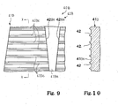
- the optical transducer system 40B includes light emitters, light detectors, optical fibers, sensor heads and optical modulators 41B, one of which is illustrated in figure 9. Although the optical modulators 41B respectively have fixtures, the fixtures are omitted from the optical modulators 41B in figures 9 and 10, and only optical modulating portions are shown. For this reason, the optical modulating portions are hereinafter labeled with references "41B". Since only the optical modulating portion 41B is different from that of the optical modulator 30, description is focused on the optical modulating portion 41 B.
- the optical modulating portion 41B is formed with a wedge pattern 42B.
- the wedge pattern 42B makes a light output surface 41Ba rough.
- Plural wedge-shaped refractors 42Ba form the wedge pattern 42B, and extend in the up-and-down direction. However, the wedge-shaped refractors 42Ba are directed oppositely to the wedge-shaped refractors 42a. Although the wedge-shaped refractors 42a are sharpened toward the downward direction, the wedge-shaped refractors 42Ba are upwardly sharpened.
- the wedge-shaped refractors 42Ba are respectively implemented by groups of ridges 42Bc extending in the fore-and-aft direction.
- the ridges 42Bc in each group are arranged in regular pitches. Since the length of ridges in each group is decreased from the lower end of the wedge-shaped refractor 42Ba toward the upper end of the wedge-shaped refractor 42Ba, the group of ridges 42Bc is seen as the wedge-shaped refractor 42Ba.
- the ridge 42c has a triangle cross section as shown in figure 10, and makes light refracted.
- the wedge-shaped refractors 42Ba are arranged in parallel to one another.
- the wedge pattern 42B is formed in the optical modulating portion 41B.
- the base portion is similar to the base portion 31, and, for this reason, is not hereinafter detailed.
- the base portion and optical modulating portion, which includes the wedge-shaped refractors 42Ba, have a unitary structure, and is formed through an injection molding.
- the optical modulating portion has a flat surface and the rough surface 41Ba.
- the ridges 42Bc make the surface 41Ba rough, and the rough surface 41Ba is reverse to the flat surface.
- the light beam is incident on the flat surface, and forms a light spot as similar to the first embodiment.
- the incident light passes through the optical modulating portion, and is output from the rough surface 41Ba.
- the light is partially refracted by means of the wedge-shaped refractors 42Ba. Since the width of each wedge-shaped refractors 42Ba is reduced toward the upper end of the optical modulating portion, the amount of light refracted is varied along the trajectory of the optical modulating portion 41B.
- the non-refracted light which is output from between the ridges 42Bc, is incident onto the end surface of the optical fiber connected to the light detector, there is not any guarantee for the refracted light to be incident on the end surface of the optical fiber.
- the amount of light incident on the optical fiber is varied in dependent on the current key position of the associated key 2a/ 2b.
- the optical modulating portion 41B converts the current key position to the light incident on the optical fiber connected to the light detector.
- the wedge-shaped refractors 42Ba are formed in the optical modulator 41B, and the wedge-shaped refractors 42Ba vary the amount of light incident on the optical fiber 10e depending upon the current key position through the refraction.
- the optical transducer system 40B exactly converts the current key position to the electric signal.
- the wedge-shaped refractors 42Ba and the remaining portion of the modulator 41Ba have the unitary structure so that the optical modulator 40B is easy to produce. For this reason, the production cost of optical modulator 41B is low so that the optical modulator 41B makes the production cost of optical transducer system 40B and, accordingly, the hybrid musical instrument low.
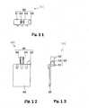
- FIGS 11, 12 and 13 show still another optical modulator 40C embodying the present invention.
- the optical modulator 40C forms a part of an optical transducer system, which is incorporated in a musical instrument.
- the optical modulator 40C has a fixture 50 and an optical modulating portion 52.
- the fixture 50 and modulating portion 52 have a unitary structure, and an injection molding is available for the optical modulator 40C.
- the miniature refractors 32c or wedge-shaped refractors 42a/ 42Ba are formed on a light output surface of the optical modulating portion 52 so that the light beam is modulated with the optical modulating portion 52.
- the optical modulating portion 52 is similar to the optical modulating portions of the optical modulators 30, 40A and 40B.
- fixture 50 is different from the base portions of the optical modulators 30, 40A and 40B. For this reason, description is hereinafter focused on the fixture 50.
- the fixture 50 makes it possible to attach the optical modulator 40C to a white key 2a or black key 2c through a single action. Any staple is not required for the assemblage.
- Two recesses (not shown), which are open onto the lower surface of the key 2a/ 2b, are to be formed in the white key 2a or black key 2b.
- the fixture 50 has an anti-rotation column 53 and a pair of hooks 54.
- the pair of hooks 54 is resiliently deformable, and the hooks 54 have wedges at the tips thereof.
- the pair of hooks 54 is inserted into one of the recesses (not shown) formed in the key 2a/ 2b, and prevents the optical modulator 40C from dropping off from the key 2a/ 2b by virtue of the increased friction between the inner surface and the wedges.
- the anti-rotation column 53 is inserted into the other of the recesses (not shown), and prevents the optical modulator from rotation about the pair of hooks 54.
- the optical modulators 30, 40A, 40B and 40C have their own unitary structures, and the unitary structures make the processes for producing the optical modulators 30, 40A, 40B and 40C simple. For this reason, the production cost of optical modulators 30, 40A, 40B and 40C is lower than the production cost of the prior art optical modulators. Since a large number of optical modulators 30, 40A, 40B or 40C are required for the musical instrument, the employment of optical transducers of the present invention permits the manufacturer of optical transducer system 10h and manufacturer of musical instruments to reduce the production cost of the optical transducer system and production cost of musical instruments.
- the mute piano does not set any limit to the technical scope of the present invention.
- the optical transducer system of the present invention may be incorporated in another sort of hybrid musical instrument such as, for example, an automatic player piano.
- the hybrid musical instrument does not set any limit to the technical scope of the present invention.
- the optical transducer system may be incorporated in an electronic musical instrument such as, for example, an electronic keyboard.
- the keyboard musical instrument does not set any limit to the technical scope of the present invention.
- Another sort of musical instrument such as, for example, a hybrid percussion instrument, a hybrid wind musical instrument or a hybrid stringed musical instrument may be equipped with the optical transducer system of the present invention.
- the vibrations of head, movements of sticks, movements of pistons/ keys vibrations of strings or movements of bows may be converted to electric signals by means of the optical transducer system of the present invention.
- the key position transducer sub-system 10a and hammer position transducer sub-system 10b do not set any limit to the technical scope of the present invention.
- the optical transducer system may further include a pedal position transducer sub-system and a plunger velocity transducer sub-system.
- an optical transducer system of the present invention may be incorporated in a hybrid wind musical instrument. In case of the hybrid wind musical instrument, a slide, a piston, a rotary valve or a key mechanism is monitored by the optical transducer system of the present invention.
- the optical transducer system of the present invention may be used in conversion from another sort of physical quantity such as, for example, velocity or acceleration to a piece of data information expressing the velocity or acceleration.
- Miniature refractors may have a bottom area expressed as a surface of n th order in so far as the ratio D1/ H is fallen within the above-described ratio where n is an even number.
- An example is a paraboloid.
- the miniature refractors may be a cone or a pyramid.
- the miniature refractors may be different in size.
- the ridges 42c/ 42Bc are arranged at the regular pitches so that the error variance method does not set any limit to the rough surface.
- Miniature caves may be formed in a transparent plate as the miniature refractors.
- the rough surface of an optical modulator of the present invention may be formed by both of the miniature projections and miniature caves.
- the optical fibers 10e and sensor heads 11 may be deleted from an optical transducer system of the present invention.
- the light emitters 10c are directly opposed to the light detectors 10d through the optical modulator 32.
- the convex lenses may be directly adhered to the ends of the optical fibers 10e, and the convex lenses of each pair are opposed to each other.
- the triangle cross section of ridges 42c and 42Bc does not set any limit to the technical scope of the present invention.
- the cross section may be polygonal or the semi-spherical, which satisfies the above-described ratio D1/ H.
- a group of semi-columns, which has a semi-circular cross section, may form each of the wedge-shaped refractors.
- the wedge shape patterns 42A and 42B do not set any limit to the technical scope of the present invention.
- the envelope of the ridges 42c or 42Bc may be curved such as, for example, a parabolic line.
- the miniature refractors 32c, wedge-shaped refractors 42a and 42Ba are formed on the light output surface.
- An optical modulator of the present invention may be formed with the refractors on a light incident surface of the optical modulator. Otherwise, the refractors may be formed on both surfaces of an optical modulator.
- the optical modulators are connected to the white keys 2a and black keys 2b so as to be moved together with the white keys 2a and black keys 2b.
- this feature does not set any limit to the technical scope of the present invention.
- a light emitter and a light detector may be connected to the moving object.
- the optical modulator is stationary.
- the optical modulator is to be relatively moved with respect to the light emitter and light detector.
- the miniature refractors 32c and wedge-shaped refractors 42a or 42Ba have a constant refractive index.
- the refractive index may be varied along the direction in which the white keys 2a or black keys 2b are moved.
- Each of the white keys 2a and black keys 2b or each of the hammers 7 serves as a "moving object".
- the current position is equivalent to a "physical quantity”.
- the light emitter 10c, optical fiber 10e, sensor head 15 as a whole constitute a “light emitting unit”, and the sensor head 16, optical fiber 10e and light detector 10d form in combination a "light detecting unit”.
- the light incident on the sensor head 16 is corresponding to "modulated light”.
- the miniature refractors 32c, wedge-shaped refractors 42a or wedge-shaped refractors 42Ba form in combination a "refracting portion".
- the optical modulators except for the optical modulating portions 32, 41A, 41B and 52 serve as a "non-refracting portion".
- the white keys 2a and black keys 2b, action units 4, hammers 7 and dampers 8a as a whole constitute "plural force transmitting paths", and the strings 8 serve as "plural tone generators".
- the pitch of tones is an “attribute” of tones.
- the loudness of tones is another "attribute” of tones.
Landscapes
- Physics & Mathematics (AREA)
- Engineering & Computer Science (AREA)
- Acoustics & Sound (AREA)
- Multimedia (AREA)
- General Physics & Mathematics (AREA)
- Electrophonic Musical Instruments (AREA)
- Mechanical Light Control Or Optical Switches (AREA)
Abstract
Description
- This invention relates to an optical transducer system and, more particularly, to an optical transducer system available for a musical instrument having movable parts to be monitored therewith and an optical modulator incorporated in the optical transducer system.
- While a player is performing a music tune on an acoustic musical instrument such as, for example, a piano, the player selectively depresses and releases the keys, and the keys make the action units drive the hammers for rotation toward the strings, and the hammers give rise to the vibrations of strings at the collision with the strings. Thus, the acoustic tones are produced only through the actuation of mechanical linkage in the acoustic musical instrument. However, an electric system and/ or an electronic system participates in generation of tones through electronic musical instruments and hybrid musical instruments. Movements of certain mechanical component parts are converted to electric signals, and the pieces of performance data, which express the movements of the certain mechanical component parts, are analyzed and processed so as to produce an audio signal expressing the tones to be produced. The audio signal is converted to the tones through a sound system. Thus, a suitable transducer system is an indispensable in the electronic musical instruments and hybrid musical instruments.
- A mute piano is a typical example of the hybrid musical instrument. The mute piano includes an acoustic piano, a hammer stopper and an electronic tone generating system. While the hammer stopper is staying outside the trajectories of the hammers, the hammer stopper does not interfere with the hammers, and a player fingers on the acoustic piano for producing the acoustic piano tones along a music passage. When the player wishes to perform a music tune without the acoustic piano tones, the player moves the hammer stopper on the trajectories of hammers. Although the player gives rise to the rotation of hammers through the fingering on the acoustic piano, the hammers rebound on the hammer stopper before striking the strings, and any acoustic piano tone is not produced in the acoustic piano. Instead, the electronic tone generating system produces an audio signal expressing electronic tones specified by the player through the fingering, and the audio signal is converted to the electronic tones through a headphone. Thus, the electronic tone generating system converts the movements of keys and the movements of hammers to the electric signals, and analyzes and processes the pieces of performance data for producing the electronic tones.
- An optical position transducer system is employed in the hybrid musical instrument. The optical position transducer system includes light emitting elements, light detecting elements and shutter plates. The light emitting elements and light detecting elements are stationary with respect to the key bed of the acoustic piano, and produce light beams across the trajectories of keys and the trajectories of hammers. The shutter plates are attached to the keys and hammers, and are moved together with the keys and hammers. The shutter plates vary the amount of light received by the light detecting elements depending upon the areas where the light beams pass.
- While the keys and hammers are moved on the trajectories, the areas are varied, and make the amount of light incident on the light detecting elements varied depending upon the current key positions on the key trajectories and the current hammer positions on the hammer trajectories. The incident light is converted to photo current so that the amount of photo current expresses the current key positions and current hammer positions.
- The shutter plate or an optical modulator is disclosed in
Japan Patent Application laid-open No. 2001- 228862 - Another shutter plate or optical modulator is disclosed in
Japan Patent Application laid-open No. 2003-44051 - In the modifications of the first and second prior art optical modulators, the black dot pattern and black wedge pattern are printed on sheets of transparent flexible film, and the sheets of printed patterns are adhered to the transparent plates.
- The third prior art optical modulator is made of metal. Through-holes are formed in the photo-shield metal plate in such a manner that the through-holes have the diameter different in a predetermined direction in which the component part of the musical instrument is moved. While the component part is traveling on the trajectory, the light spot is moved on the non-transparent metal plate. The light beam is partially shielded with the photo-shield metal plate, and is partially transmitted through the through-holes. Since the diameter of through-holes is varied in the predetermined direction, the amount of light incident on the light detecting element is varied together with the current position of the component part. Thus, the current position of component part is converted to the amount of light varied depending upon the movement of the component part.
- Although the current position of component part is surely converted to the electric signal by means of the prior art optical modulators, a problem is encountered in the first, second and third prior art optical modulators in that the prior art optical modulators make the production cost of the hybrid musical instrument increased.
- In detail, the manufacturer firstly prepares the transparent plate for the first prior art shutter. Thereafter, the manufacturer prints the black dot pattern or black wedge pattern on a major surface of the transparent plate.
- Otherwise, the manufacturer prints the black dot pattern or black wedge pattern on a sheet of flexible film, and, thereafter, adheres the printed sheet of flexible film onto the major surface of the transparent plate. Thus, the first prior art optical modulator and second prior art optical modulator are fabricated through the prior art process having two steps or three steps.
- The prior art fabrication process for the third prior art shutter is more complicated. The manufacture firstly prepares the photo-shield metal plate. Subsequently, the manufacturer forms the through-holes in the photo-shield metal plate by using twisted drills. In order to make the through-holes different in diameter, it is necessary to repeat the drill work with different twisted drills.
- Otherwise, the manufacturer overlays a photo-sensitive layer on the photo-shield metal plate, and the pattern of holes is optically transferred from a mask to the photo-sensitive layer for producing a latent image in the photo-sensitive layer. The latent image is developed, and a photo-sensitive mask is prepared on the photo-shield plate. The multiple layered structure of photo-shield plate and photo-sensitive layer is exposed to etchant. Then, the photo-shield metal plate is partially etched away, and the prior art shutter is obtained. The machining process or photo-lithographic process are complicated, and are costly.
- All of the prior art optical modulators are fabricated through the complicated processes, and, accordingly, the production cost is high. A lot of optical modulators are required for the musical instrument. This results in the high production cost of the musical instrument.
- It is therefore an important object of the present invention to provide an optical transducer system, which is reduced in production cost.
- It is another important object of the present invention to provide an optical modulator, which is used in the optical transducer system.
- It is also an important object of the present invention to provide a musical instrument, which is equipped with the optical transducer system.
- To accomplish the objects, the present invention proposes to modulate light through refraction.
- In accordance with one aspect of the present invention, there is provided an optical transducer system for converting a physical quantity of a moving object to an electric signal, and the optical transducer system comprises a light emitting unit radiating a light beam across a trajectory of the moving object, a light detecting unit stationary with respect to the light emitting unit and receiving modulated light so as to convert the modulated light to the electric signal and an optical modulator relatively moved with respect to the light emitting unit and the light detecting unit due to the movement of the moving object on the trajectory, producing the modulated light from the light beam fallen thereon and having a non-refracting portion transparent to the light beam so as to produce a part of the modulated light and a refracting portion varying the amount of another part of the modulated light through refraction of the light beam depending upon the physical quantity of the moving object on the trajectory.
- In accordance with another aspect of the present invention, there is provided an optical modulator relatively moved with respect to a light emitting unit radiating a light beam and a light detecting unit receiving modulated light, and the optical modulator comprises a non-refracting portion transparent to the light beam and producing a part of the modulated light and a refractor varying the amount of another part of the modulated light through refraction of the light beam depending upon the physical quantity of a moving object.
- In accordance with yet another aspect of the present invention, there is provided a musical instrument for producing tones comprises plural force propagating paths on which force is selectively exerted for specifying an attribute of tones and having certain component parts, respectively, plural tone generators provided in association with the plural force propagating paths, respectively, and producing the tones at the attribute, an optical transducer system converting a physical quantity of the certain component parts to electric signals and including plural light emitting units radiating light beams across trajectories of the certain component parts, respectively, plural light detecting units stationary with respect to the light emitting units and receiving modulated light so as to convert the modulated light to the electric signals and plural optical modulators relatively moved with respect to the light emitting units and the light detecting units due to the movements of the certain component parts on the trajectories for producing the modulated light from the light beams fallen thereon, respectively, and an information processing system connected to the plural light detecting units and processing pieces of data information expressing said physical quantity of said certain component parts for producing pieces of music data expressing said tones, and each of the optical modulators has a non-refracting portion transparent to the light beam so as to produce a part of the modulated light and a refracting portion varying the amount of another part of the modulated light through refraction of the light beam depending upon the physical quantity of the moving object on the trajectory.
- The features and advantages of the optical transducer system, optical modulator and musical instrument will be more clearly understood from the following description taken in conjunction with the accompanying drawings, in which
- Fig. 1 is a cross sectional side view showing a mute piano according to the present invention,
- Fig. 2 is a partially cross sectional side view showing an optical sensor head unit incorporated in the mute piano,
- Fig. 3A is a front view showing an optical modulator attached to a white key of the mute piano,
- Fig. 3B is a side view showing the optical modulator,
- Fig. 3C is a plane view showing a base portion of the optical modulator,
- Fig. 4A is a side view partially enlarged and showing a surface of the optical modulator,
- Fig. 4B is a cross sectional view taken along line IV- IV in figure 4A, and showing miniature refractors formed on a surface of the optical modulator,
- Fig. 5A is a cross sectional view showing light passing through a miniature refractor,
- Fig. 5B is a cross sectional view showing the optical modulator between sensor heads,
- Fig. 6 is a side view showing wedge-shaped refractors formed in another optical modulator according to the present invention,
- Fig. 7 is a side view showing a part of the wedge-shaped refractors at large magnification ratio,
- Fig. 8 is a cross sectional view taken along line VIII - VIII in figure 7 and showing ridges forming the wedge-shaped refractors,
- Fig. 9 is a side view showing a part of another wedge-shaped refractor formed in yet another optical modulator according to the present invention,
- Fig. 10 is a cross sectional view taken along line X - X in figure 9 and showing ridges forming the wedge-shaped refractor,
- Fig. 11 is a plane view showing still another optical modulator according to the present invention,
- Fig. 12 is a side view showing the optical modulator, and
- Fig. 13 is a front view showing the optical modulator.
- A musical instrument embodying the present invention largely comprises plural force propagating paths, plural tone generators, an optical transducer system and an information processing system. Force is selectively exerted on the plural force propagating paths for specifying an attribute of tones such as, for example, the pitch of tones. The force is propagated through the force propagating paths to the plural tone generators, and makes the tone generators produce tones at the specified attribute.
- The plural force propagating paths have certain component parts, respectively. While the force is propagating through one of the plural force propagating paths to the associated tone generator, the certain component part is activated during the propagation of force. For this reason, the attribute of tones to be produced is presumable through the behavior of certain component parts. In order to monitor the certain component parts, the optical transducer system is provided for the certain component parts.
- The optical transducer system is expected to convert a physical quantity of the certain component parts to electric signals, and includes plural light emitting units, plural light detecting units and plural optical modulators. Light beams are radiated from the light emitting units toward the light detecting units across trajectories of the certain component parts, respectively. Although the light detecting units are stationary with respect to the associated light emitting units, the optical modulators are relatively moved with respect to the light emitting units and light detecting units due to the movements of the certain component parts. The light beams are fallen on the optical modulators, and the optical modulators modulate the light beams during the movements of the certain component parts. The modulated light is incident on the light detecting units, and is converted to the electric signal expressing the physical quantity of the certain component parts.
- The electric signals are supplied from the light detecting units to the information processing system. As described hereinbefore, the attribute of tones are presumable on the basis of the behavior of certain component parts. The information processing system processes pieces of data information expressing the physical quantity of certain component parts so as to determine the tones to be produced. The information processing system produces pieces of music data expressing the tones to be produced.
- There are various ways to use the pieces of music data. The pieces of music data may be supplied to another musical instrument for a remote concert. In case where the musical instrument is equipped with a sound system, the tones are produced on the basis of the pieces of music data by means of the sound system. In case where the musical instrument is equipped with an automatic playing system, the automatic playing system selectively exerts the force on the plural force propagating paths for producing the tones through the tone generators.
- The optical modulator is hereinafter detailed. Each of the optical modulators has a non-refracting portions and a refracting portion. The non-refracting portion is transparent to the light beam so as to produce a part of the modulated light. On the other hand, the refracting portion varies the amount of another part of the modulated light through refraction of the light beam depending upon the physical quantity of the moving object on the trajectory. The part of modulated light and another part of modulated light are incident on the associated light detecting unit, and the incident light is converted to the electric signal.
- As will be appreciated from the foregoing description, each of the optical modulators has the refracting portion so that the light beam is modulated through the refraction. It is easy for the manufacturer to make the non-refracting portion and refracting portion concurrently produced in the optical modulator. For this reason, the optical modulator is low in production cost, and makes the optical transducer system and musical instrument reduced in production cost.
- In the following description, term "front" is indicative of a position closer to a player, who is sitting on a stool for fingering, than a position modified with term "rear". A line drawn between a front position and a corresponding rear position extends in a "longitudinal direction", and a lateral direction crosses the longitudinal direction at right angle. An up-and-down direction is normal to a plane defined by the longitudinal direction and lateral direction.
- Referring first to figure 1 of the drawings, a mute piano embodying the present invention largely comprises an
acoustic piano 1, an opticalposition transducer system 10, aninformation processing system 60, asound system 70 and amute system 80. An upright piano serves as theacoustic piano 1. Theoptical transducer system 10,information processing system 60 andmute system 70 are installed inside theacoustic piano 1. However, thesound system 70 is partially exposed to the environment. - A player fingers on the
acoustic piano 1 for music tunes, and the acoustic piano tones or electronic tones are produced through theacoustic piano 1 orsound system 70. Theoptical transducer system 10,information processing system 60 andsound system 70 participate in the generation of electronic tones as follows. - The
optical transducer system 10 is electrically connected to theinformation processing system 60, which in turn is electrically connected to thesound system 70. Theacoustic piano 1 is monitored by theoptical transducer system 10, and pieces of action data expressing the fingering on the acoustic piano are supplied from theoptical transducer system 10 to theinformation processing system 60. Theinformation processing system 60 processes the pieces of action data, and determines the electronic tones specified through the fingering. Theinformation processing system 60 produces an audio signal, and supplies the audio signal to thesound system 70. The audio signal is converted to the electric tones through thesound system 70. - The
mute system 80 is changed between a free position and a blocking position. While themute system 80 is staying at the free position, themute system 80 permits theacoustic piano 1 to produce the acoustic piano tones. However, when themute system 80 is changed to the blocking position, themute system 80 prohibits theacoustic piano 1 from producing the acoustic piano tones. The player hears the electronic tones instead of the acoustic piano tones. - The
acoustic piano 1 includes akeyboard 2,action units 4, apiano cabinet 6, hammers 7, strings 8 and damper units 9. Thepiano cabinet 6 has akey bed 6a, and defines an inner space. Thekeyboard 2 is mounted on thekey bed 6a, and is exposed to a player, who is sitting in front of thekeyboard 2 for fingering. Akey slip 6b extends in the lateral direction along the front end surface of thekey bed 6a, and the space under thekeyboard 2 is hidden at the back of thekey slip 6b. Theaction units 4, hammers 7, strings 8 and damper units 9 are housed inside thepiano cabinet 6, and cooperate with one another for producing the acoustic piano tones. - The
keyboard 2 includeswhite keys 2a, black keys 2b, abalance rail 3, aback rail 5, a key frame 5a and front rails 9. The pitch names are respectively assigned to thekeys 2a/ 2b so that a player specifies the pitch of tones by selectively depressing thewhite keys 2a and black keys 2b. The front rails 9 extends in the lateral direction at the back of thekey slip 6b, and are located below the front end portion of thekeyboard 2. Thebalance rail 3 extends in parallel to the front rails 9, and is spaced from the front rails 9 in the longitudinal direction. Theback rail 5 extends in parallel to thebalance rail 3, and is spaced from thebalance rail 5 in the longitudinal direction. Thus,front pace 2c takes place under the front portions of white andblack keys 2a/ 2b between the front rails 9 and thebalance rail 3, andrear space 2d takes place under the rear portions of white andblack keys 2a/ 2b between thebalance rail 3 and theback rail 5. Thebalance rail 3,back rail 5 and front rails 9 are tied with the key frame 5a. - The
white keys 2a and black keys 2b extends in parallel to one another in the longitudinal direction, and are supported on thebalance rail 3 by means ofbalance pins 3a. Thewhite keys 2a and black keys 2b independently pitch up and down. Pairs offront pins 9a upwardly project from the front rails 9, and each pair offront pints 9a is provided for one of the white andblack keys 2a/ 2b. A pair of recesses is formed in each of the white andblack keys 2a/ 2b, and receives the pair offront pins 9a. The pairs offront pins 9a guide the white andblack keys 2a/ 2b to the front rails 9, and prevent the white andblack keys 2a/ 2b from deviation from key trajectories in the lateral direction.Capstan buttons 2e are upright on the rear portions of white andblack keys 2a/ 2b. - While any force is not exerted on the upper surface of the
white keys 2a and black keys 2b, thewhite keys 2a and black keys 2b stay at respective rest positions. The force on the front portions makes thewhite keys 2a and black keys 2b getting closer and closer to the front rails 9. When thewhite keys 2a and black keys 2b are brought into contact with the front rails 9, thewhite keys 2a and black keys 2b reach respective end positions. - The
action units 4 are arrayed in the lateral direction, and are rotatably supported by a center rail 6c of thepiano cabinet 6. Theaction units 4 are associated with the white andblack keys 2a/ 2b, respectively, and thecapstan buttons 2e are held in contact with the associatedaction units 4. Thus, the white andblack keys 2a/ 2b are linked with theaction units 4 through thecapstan buttons 2e so that the movements of white and black key 2a/ 2b give rise to actuation of associatedaction units 4. The behavior ofaction units 4 are well known to persons skilled in the art, and no further description is hereinafter incorporated for the sake of simplicity. - The strings 8 are stretched on a sound board (not shown) of the
piano cabinet 6, and are opposed to thehammers 7, respectively. The damper units 8a are respectively driven by the actuatedaction units 4 so as to be spaced from the associated strings 8 and brought into contact with the associated strings 8. While theaction units 4 keep the damper units 8a spaced from the strings 8, the strings 8 are vibratory. On the other hand, while theaction units 4 is permitting the damper units 8a to be held in contact with the strings 8, the damper units 8a prohibit the strings 8 from vibrations. - The
hammers 7 are rotatably supported by the center rail 6c, and are linked with theaction units 4, respectively. While a player is depressing a white key 2a or black key 2b, thedepressed key 2a/ 2b actuates the associatedaction unit 4. The actuatedaction units 4 make the damper units 8a spaced from the strings 8, and, thereafter, give rise to rotation of the associated hammers 7 toward the associated strings 8. Thehammers 7 are brought into collision with the strings 8, and give rise to the vibrations of strings 8. The acoustic piano tones are radiated from the vibrating strings 8. - The
optical transducer system 10 includes a keyposition transducer sub-system 10a and a hammerposition transducer sub-system 10b. Since the hammerposition transducer sub-system 10b is similar in structure to the keyposition transducer system 10a, the keyposition transducer system 10a is hereinafter detailed, and description on the hammerposition transducer sub-system 10b is omitted for the sake of simplicity. - The key
position transducer sub-system 10a includeslight emitters 10c,light detectors 10d,optical fibers 10e, an opticalsensor head unit 10h andoptical modulators 30. Thelight emitters 10c are connected through a bundle of theoptical fibers 10e to the opticalsensor head unit 10h, which in tern is connected through another bundle ofoptical fibers 10e to thelight detectors 10d. The opticalsensor head unit 10h is mounted on the key frame 5a, and is accommodated in thefront space 2c between the front rails 9 and thebalance rail 3. For this reason, the opticalsensor head unit 10h is stationary with respect to thekey bed 6a. On the other hand, theoptical modulators 30 are respectively attached to thelower surfaces 2h of the white andblack keys 2a/ 2b, and are hung from thelower surfaces 2h. For this reason, theoptical modulators 30 are movable on predetermined trajectories together with the white andblack keys 2a/ 2b. The predetermined trajectories extend across light beams produced in the opticalsensor head unit 10h so that the amount of light of each light beam is varied with associated one of theoptical modulators 30 depending upon the current key position of the associated white key 2a or black key 2b. - Turning to figure 2 of the drawings, the optical
sensor head unit 10h is illustrated in detail. The opticalsensor head unit 10h includes abase plate 13, aframework 12,adjusters base plate 13 is secured to the key frame 5a, and theadjusters base plate 13. Theframework 12 laterally extends over thebase plate 13 between theadjusters base plate 13 through theadjusters framework 12 at a proper height by means of theadjusters -
Slits 12a are formed in theframework 12, and each of theslits 12a is laterally spaced from theadjacent slits 12a by a distance equal to the distance between the centerlines on thelower surfaces 2h of white andblack keys 2a/ 2b. Theoptical modulators 30 have the centerlines aligned with the centerlines of thelower surfaces 2h of white andblack keys 2a/ 2b. For this reason, theoptical modulators 30 are respectively aligned with theslits 12a, and project through theslits 12a intospace 12b below theframework 12. - The sensor heads 11 are provided below the
framework 12, and are bolted to theframework 12 at intervals. The sensor heads 11 are arranged in such a manner as to be alternated with theslits 12a. Each of the sensor heads 11 has twolight ports light ports 15 is directed to the light port of theadjacent sensor head 11 on the left side, and the other of thelight ports 16 is directed to the light port of theadjacent sensor head 11 on the right side. Everyother sensor head 11 is optically connected to selected one of thelight emitters 10c, and the remaining sensor heads 11 are optically connected to thelight detectors 10d. The sensor heads 11, which are connected to thelight emitters 10c, radiate the light beams across theslits 12a toward the sensor heads 11, which are connected to thelight detectors 10d. The light beams pass through theoptical modulators 30, and are incident on the light ports of the adjacent sensor heads 11 connected to thelight detectors 10d. - The
light emitters 10c are sequentially energized in such a manner that each of the sensor heads 11, which is connected to one of thelight detectors 10d, does not concurrently receive two light beams radiated from the adjacent sensor heads 11. The incident light is propagated to thelight detectors 10d, and is converted to photocurrent in thelight detectors 10d. The photocurrent flows into a suitable current-to-voltage converter (not shown) such as, for example, resistors, and the electric signals, which are representative of the current key positions, are supplied to theinformation processing system 60. - The
optical modulator 30 has a unitary structure, and is made of transparent synthetic resin such as, for example, polycarbonate. The transparent synthetic resin is resiliently deformable. In this instance, theoptical modulator 30 is prepared through an injection molding, and does not contain any coloring agent. A single sort of synthetic resin, i.e., polycarbonate is used in the injection molding. - The
optical modulator 30 has abase portion 31 and anoptical modulating portion 32. As will be better seen in figures 3A, 3B and 3C, thebase portion 31 projects from the optical modulatingportion 32 in rightward, and is formed with twoholes 31d. In this instance, theholes 31d are generally elliptical. The twoholes 31d are spaced from each other in the longitudinal direction, and a tie plate portion 31 b is left between the twoholes 31d. The tie plate portion 31 b is merged with the right peripheral portion 31b, and is spaced from the leftperipheral portion 31c. - The
optical modulator 30 is secured to the associated white key 2a or black key 2b by means of a staple (not shown). In the assembling work, theoptical modulator 30 is put on thesurface 2h, and the optical modulatingportion 32 is aligned with the centerline of the white key 2a or black key 2b. The tips of staple are stuck into the portions of key 2a/ 2b exposed to the twoholes 31d, and the staple is driven into the key 2a/ 2b. The staple thus driven into the key 2a/ 2b presses the tie plate portion 31 b to thesurface 2h so that theoptical modulator 30 is secured to the white key 2a or black key. 2b. When theoptical modulator 30 is secured to the white key 2a or black key 2b, the optical modulatingportion 32 extends in the up-and-down direction, and the light beam is incident on the optical modulatingportion 32 at right angle. - The
optical modulating portion 32 has aflat surface 32a and arough surface 32b. Therough surface 32b serves as a refractor. In this instance, therough surface 32b or refractor causes the amount of transmitted light per unit area to be varied in the up-and-down direction through the refraction. - As will be better seen in figures 4A and 4B, a large number of
miniature refractors 32c form therough surface 32b. Theminiature refractors 32c and remaining portion of the optical modulatingportion 32 are unitary. While the white key 2a or black key 2b is staying at the rest position, the light beam is fallen onto the optical modulatingportion 32, and alight spot B 1 takes place. When the white key 2a or black key 2b reaches the end position, the light spot B2 is found on thelight modulating portion 32. Thus, the light beam is moved from thelight spot B 1 to the light spot B2 along a trajectory L during the travel of the white key 2a or black key 2b on the key trajectory. The distance S between the light spot B1 and the light spot B2 is equal to the stroke of white key 2a or the stroke of black key 2b. The area of light spot B1/ B2 is equal to the unit area so that the amount of refracted light of the light beam is varied along the trajectory L. - The
miniature refractors 32c have a semi-spherical configuration. The term "semi-spherical" means that the miniature refractors have circular bottom area. Theminiature refractors 32c are 0.03 millimeter in height H, and are 0.07 millimeter in diameter D1. In this instance, the ratio between the height and the diameter, i.e., D1/ H is of the order of 2.33. Although another optical modulator of the present invention may be formed with miniature refractors different in height and diameter from theminiature refractors 32c, it is desirable to make the ratio between the height H anddiameter D 1 fallen into a range of 2.33 ± 20 %. In order to prevent theoptical modulator 30 from the shrinkage cavity inherent in the injection molding, it is desirable to make the height H of miniature refractors fallen within a range (0.05 × D1) ≦ H ≦ (0.5 × D1). - The density of the
miniature refractors 32c is varied from an upper area of therough surface 32 to a lower area of therough surface 32. Theminiature refractors 32c are concentrated in the upper area as shown in circle CL1 at a large magnification ratio, and become sparse in the lower area as shown in circle CL3 at the large magnification ratio. The density ofminiature refractors 32c is linearly decreased from the upper area toward the lower area along the trajectory L so that theminiature refractors 32c are less crowded in an intermediate area as shown in circle CL2 at the large magnification ratio. - In this instance, the density of
miniature refractors 32c is made varied through an error variance method, which was employed in the prior art process disclosed in the above-mentionedJapanese Patent Application laid-open 2001-228862 - As to the number of
miniature refractors 32c per unit area, which is as wide as the light spot B1/ B2, the optical modulating portion has a minimum of 25miniature refractors 32c. In other words, there are 25miniature refractors 32c in the light spot B1. - The maximum diameter Dmax of light spot B1/ B2 is determined as follows. The length L1, which is the distance between the upper end of the optical modulating
portion 32 and the lower end of the optical modulatingportion 32, is expressed as
where L0 is the distance between the upper end of the optical modulating portion at the rest position and the lower end of the optical modulating portion at the end position.
The maximum diameter Dmax of the light spot B1/ / B2 is to satisfyequation 2.
equations 
- Description is hereinafter made on how the light beam is modulated by means of the
miniature refractors 32c. Figure 5A shows the light passing through theminiature refractor 32c, and figure 5B shows the optical beam across theoptical modulator 32 between thelight ports sensor head 11 radiates the light beam from thelight port 15 toward thelight port 16 of theother sensor head 11. Though not shown in figure 5B, thelight port 15 has a convex lens, and the convex lens makes the emitted lightparallel rays 20. Thelight port 16 has acondenser lens 16a, and the light is incident on theoptical fiber 10e. Theoptical fiber 10e guides the incident light to thelight detector 10d. - The light beam is fallen on the
flat surface 32a at right angle, and forms the light spot B. The transparent optical modulatingportion 32 allows the light in the light spot B to pass therethrough. As described hereinbefore, theminiature refractors 32c are formed on therough surface 32b. However, theminiature refractors 32c are spaced from one another. In other words, theminiature refractors 32c are surrounded by a flat surface 32ba. The flat surface 32ba is in parallel to theflat surface 32a. In this situation, theparallel rays 20 are refracted through theminiature refractors 32c as indicated byarrows 20a. The angle of refraction is dependent on the radius of curvature of the surface ofminiature refractors 32c. However, theparallel rays 20 are output from the flat surface 32ba substantially without any refraction as indicated byarrows 20b. - The
condenser lens 16a is designed to make therays 20b incident on the end surface of theoptical fiber 10e. However, there is not any guarantee for the refractedrays 20a to be fallen on the end surface of theoptical fiber 10e. For this reason, most of the refractedrays 20a do not reach thelight detector 10d. - As described hereinbefore, the density of
miniature refractors 32c is varied along the trajectory L so that the amount of light incident on the end surface ofoptical fiber 10e is also varied along the trajectory L. Thus, the current key position is converted to the amount of incident light and, accordingly, the amount of photocurrent by virtue of theoptical modulator 30 of the present invention. - The
optical modulator 30 is produced as follows. First, a molding die unit (not shown) is prepared for an injection molding. A cavity, which has contours corresponding to those of theoptical modulator 30, is formed in the molding die unit, and semi-spherical miniature recesses are open to the inner surface of the molding die unit. - Molten synthetic resin is injected into the cavity of the molding die unit. The molten synthetic resin is solidified in the molding die unit. After the solidification, the
optical modulator 30, which is formed with a large number ofminiature refractors 32c, is taken out from the molding die unit. Thus, theoptical modulator 30 is produced only through the injection molding. Other production steps such as, for example, the printing work, adhesion to the transparent plate and lithography are not required for theoptical modulator 30. For this reason, theoptical modulator 30 is economically produced. The reduction in production cost ofoptical modulators 30 make the manufacturer to offer the mute piano at a low price. - The
optical modulating portion 32 andbase portion 31 have the unitary structure. The unitary structure is desirable for the simple assembling work. The worker is expected to drive the staple into the white key 2a or black key 2b through theholes 31d. Theoptical modulators 30 are attached to all of thekeys 2a/ 2b, respectively, and theacoustic piano 1 typically has eighty-eightkeys 2a/ 2b. The worker repeats the assembling work on the optical modulator eighty-eight times. Theoptical modulator 30 makes the time and labor in the assembling work surely reduced. - The
miniature refractors 32c are conducive to high resolution of the current key position. The large number ofminiature refractors 32c makes the amount of light gently varied along the key trajectory. Even though the white key 2a or black key 2b is moved over an extremely short distance, the amount of light is varied so that the extremely short distance is converted to the electric signal. - Turning back to figure 1, the
information processing system 60 includes aninformation processor 61 and atone generator 62. Theinformation processor 61 has a data processing capability and a large data holding capability, and a computer program runs on theinformation processor 61. Various takes are achieved through the execution of instruction codes of the computer program. - The computer program is broken down into a main routine program and subroutine programs. While the main routine program is running on the
information processor 61, users are communicable with theinformation processing system 60. For example, a user gives his or her instructions to theinformation processor 61, and acquires pieces of knowledge about the current status of theinformation processing system 60. - The
information processor 61 periodically fetches pieces of positional data expressing the current key positions and current hammer positions from a data interface through execution of instruction codes in one of the subroutine programs, and the pieces of positional data are stored in a suitable memory in theinformation processor 61. - When a user instructs the
information processing system 60 to change thesilent system 80, the main routine program braches to another subroutine program, and theinformation processor 61 supplies a driving signal for changing thesilent system 80. - While a user is fingering on the
keyboard 2, the main routine program periodically branches to yet another subroutine program, and produces music data codes through analysis on the pieces of positional data. - The
tone generator 62 has a waveform memory, and pieces of waveform data, which express the waveforms of tones, are stored in the waveform memory. When the music data code expressing a note-on event is supplied from theinformation processor 61 to thetone generator 62, a series of pieces of waveform data is read out from the waveform memory, and an audio signal is produced from the pieces of waveform data. When the music data code expressing a note-off event reaches to thetone generator 62, thetone generator 62 makes the audio signal decayed. - As described hereinbefore, the
optical transducer system 10h of the present invention accurately converts the current key positions and current hammer positions to the electric signals. Theinformation processor 61 accurately determines the key velocity, timing at which the electronic tone is to be produced and timing at which the electronic tone is to be decayed. Thus, theoptical transducer system 10h of the present invention is conducive to the electronic tones at high fidelity. - The
sound system 70 includesamplifiers 71 and aheadphone 72. Small-sized loud speakers may be further incorporated in thesound system 70. The audio signal is equalized and amplified in theamplifiers 71, and is converted to the electronic tones through theheadphone 72 after the amplification. - The
mute system 80 includes a hammer stopper 81 and an electric motor unit 82. The hammer stopper 81 extends in the space between thehammers 7 and the strings 8 in the lateral direction, and is changed between a free position and a blocking position by means of the electric motor unit 82. - While the hammer stopper 81 is staying at the free position, the
hammers 7 are brought into collision with the strings 8 without any interference of the hammer stopper 81. For this reason, the acoustic piano tones are produced through the vibrations of the strings 8. - When the driving signal is supplied from the
information processor 61 to the electric motor unit 82, the electric motor unit 82 changes the hammer stopper 81 from the free position to the blocking position, and the hammer stopper 81 is moved into the trajectories ofhammers 7. Although thehammers 7 escape from theaction units 4, thehammers 7 rebound on the hammer stopper 81 before reaching the strings 8 so that any acoustic piano tone is not produced. A player hears the electronic tones instead of the acoustic piano tones. Thus, thesilent system 80 makes it possible to practice the fingering on thekeyboard 2 without disturbance to the neighborhood. - As will be understood from the foregoing description, the
optical modulator 30 of the present invention has the miniature refractors, the density of which is varied in the direction in which the light spot B1/ B2 is moved. The miniature refractors vary the amount of refracted light and, accordingly, the amount of light incident on theoptical fiber 10e depending upon the current position of the associated white key 2a or black key 2b. As a result, the current key position is exactly converted to the electric signal. - The
optical modulator 30 has the unitary structure, and is, by way of example, produced through the molding. Thus, the optical transducer is appropriate to the mass-production. The manufacturer can reduce the production cost ofoptical transducer 10h and, accordingly, the mute piano. - Turning to figure 6, another hybrid keyboard musical instrument embodying the present invention also comprises an acoustic piano, an information processing system, a sound system, a mute system and an optical transducer system 40A. Since the acoustic piano, information processing system, sound system and mute system are similar to the
acoustic piano 1,information processing system 60,sound system 70 andmute system 80, no further description is hereinafter incorporated for avoiding repetition. When component parts of the acoustic piano, information processing system, sound system and mute system are referred to in the following description, the component parts are labeled with the references designating the corresponding component parts of theacoustic piano 1,information processing system 60,sound system 70 andmute system 80. - The optical transducer system 40A includes light emitters, light detectors, optical fibers, sensor heads and
optical modulators 41A, one of which is illustrated in figure 6. Although theoptical modulators 41 A have respective fixtures, the fixtures are not shown in figure 6, and only optical modulating portions of theoptical modulators 41 A are illustrated. For this reason, the optical modulating portions are hereinafter labeled with thereferences 41A. Since only theoptical modulating portion 41A is different from that of theoptical modulator 30, description is hereinafter focused on theoptical modulating portion 41A. - The
optical modulating portion 41 A is formed with wedge-shapedrefractors 42a instead of theminiature refractors 32c. The wedge-shapedrefractors 42a are respectively implemented by groups ofridges 42c extending in the up-and-down direction as shown in figure 7. Theridges 42c extend at regular intervals. Since the length of ridges in each group is decreased from the centerline of the wedge-shapedrefractor 42a toward both sides of the wedge-shapedrefractor 42a, the group ofridges 42c is seen as the wedge-shapedrefractor 42a. Theridge 42c has a triangle cross section as shown in figure 8, and makes light refracted. The wedge-shapedrefractors 42a are arranged in parallel to one another, and form awedge pattern 42A. - Although the wedge-shaped
refractors 42a are colored in black in figure 6, the wedge-shapedridges 42a, i.e., the groups ofridges 42c are colorless, and are transparent. The coloration is made for the sake of better understanding of the wedge-shapedrefractors 42a. - The
wedge pattern 42A is formed in the optical modulatingportion 41 a. The base portion is similar to thebase portion 31, and, for this reason, is not hereinafter detailed. The base portion and optical modulatingportion 41 a, which includes the wedge-shapedrefractors 42a, have a unitary structure, and is formed through an injection molding. - The
optical modulating portion 41a has a flat surface and a rough surface 41aa. Theridges 42c make the surface 41aa rough, and the rough surface 41 aa is reverse to the flat surface. The light beam is incident on the flat surface, and forms a light spot as similar to the first embodiment. The incident light passes through theoptical modulating portion 41a, and is output from the rough surface 41aa. - When the light is output from the rough surface 41 aa, the light is partially refracted by means of the wedge-shaped
refractors 42a. Since the width of each wedge-shapedrefractors 42a is reduced toward the lower end of theoptical modulating portion 41A, the amount of light refracted is varied along the trajectory of theoptical modulating portion 41A. Although the non-refracted light, which is output from between theridges 42c, is incident onto the end surface of the optical fiber connected to the light detector, there is not any guarantee for the refracted light to be incident on the end surface of the optical fiber. Thus, the amount of light incident on the optical fiber is varied in dependent on the current key position of the associated key 2a/ 2b. In other words, the optical modulatingportion 41 A converts the current key position to the light incident on the optical fiber connected to the light detector. - As will be understood from the foregoing description, the wedge-shaped
refractors 42a are formed in theoptical modulator 41A, and the wedge-shapedrefractors 42a vary the amount of light incident on theoptical fiber 10e depending upon the current key position through the refraction. Thus, the optical transducer system 40A exactly converts the current key position to the electric signal. - The wedge-shaped
refractors 42a and the remaining portion ofoptical refractor 41A have the unitary structure so that theoptical modulator 41A is easy to produce. For this reason, the production cost ofoptical modulator 41A is low so that theoptical modulators 41A make the production cost of optical transducer system 40A and, accordingly, the hybrid musical instrument low. - Yet another hybrid keyboard musical instrument embodying the present invention also comprises an acoustic piano, an information processing system, a sound system, a mute system and an optical transducer system 40B. Since the acoustic piano, information processing system, sound system and mute system are similar to the
acoustic piano 1,information processing system 60,sound system 70 andmute system 80, no further description is hereinafter incorporated for the sake of simplicity. When component parts of the acoustic piano, information processing system, sound system and mute system are referred to in the following description, the component parts are labeled with the references designating the corresponding component parts of theacoustic piano 1,information processing system 60,sound system 70 andmute system 80. - The optical transducer system 40B includes light emitters, light detectors, optical fibers, sensor heads and
optical modulators 41B, one of which is illustrated in figure 9. Although theoptical modulators 41B respectively have fixtures, the fixtures are omitted from theoptical modulators 41B in figures 9 and 10, and only optical modulating portions are shown. For this reason, the optical modulating portions are hereinafter labeled with references "41B". Since only theoptical modulating portion 41B is different from that of theoptical modulator 30, description is focused on the optical modulatingportion 41 B. - The
optical modulating portion 41B is formed with a wedge pattern 42B. The wedge pattern 42B makes a light output surface 41Ba rough. Plural wedge-shaped refractors 42Ba form the wedge pattern 42B, and extend in the up-and-down direction. However, the wedge-shaped refractors 42Ba are directed oppositely to the wedge-shapedrefractors 42a. Although the wedge-shapedrefractors 42a are sharpened toward the downward direction, the wedge-shaped refractors 42Ba are upwardly sharpened. - The wedge-shaped refractors 42Ba are respectively implemented by groups of ridges 42Bc extending in the fore-and-aft direction. The ridges 42Bc in each group are arranged in regular pitches. Since the length of ridges in each group is decreased from the lower end of the wedge-shaped refractor 42Ba toward the upper end of the wedge-shaped refractor 42Ba, the group of ridges 42Bc is seen as the wedge-shaped refractor 42Ba. The
ridge 42c has a triangle cross section as shown in figure 10, and makes light refracted. The wedge-shaped refractors 42Ba are arranged in parallel to one another. - The wedge pattern 42B is formed in the
optical modulating portion 41B. The base portion is similar to thebase portion 31, and, for this reason, is not hereinafter detailed. The base portion and optical modulating portion, which includes the wedge-shaped refractors 42Ba, have a unitary structure, and is formed through an injection molding. - The optical modulating portion has a flat surface and the rough surface 41Ba. The ridges 42Bc make the surface 41Ba rough, and the rough surface 41Ba is reverse to the flat surface. The light beam is incident on the flat surface, and forms a light spot as similar to the first embodiment. The incident light passes through the optical modulating portion, and is output from the rough surface 41Ba. When the light is output from the rough surface 41Ba, the light is partially refracted by means of the wedge-shaped refractors 42Ba. Since the width of each wedge-shaped refractors 42Ba is reduced toward the upper end of the optical modulating portion, the amount of light refracted is varied along the trajectory of the
optical modulating portion 41B. Although the non-refracted light, which is output from between the ridges 42Bc, is incident onto the end surface of the optical fiber connected to the light detector, there is not any guarantee for the refracted light to be incident on the end surface of the optical fiber. Thus, the amount of light incident on the optical fiber is varied in dependent on the current key position of the associated key 2a/ 2b. In other words, theoptical modulating portion 41B converts the current key position to the light incident on the optical fiber connected to the light detector. - As will be understood from the foregoing description, the wedge-shaped refractors 42Ba are formed in the
optical modulator 41B, and the wedge-shaped refractors 42Ba vary the amount of light incident on theoptical fiber 10e depending upon the current key position through the refraction. Thus, the optical transducer system 40B exactly converts the current key position to the electric signal. - The wedge-shaped refractors 42Ba and the remaining portion of the modulator 41Ba have the unitary structure so that the optical modulator 40B is easy to produce. For this reason, the production cost of
optical modulator 41B is low so that theoptical modulator 41B makes the production cost of optical transducer system 40B and, accordingly, the hybrid musical instrument low. - Figures 11, 12 and 13 show still another
optical modulator 40C embodying the present invention. Theoptical modulator 40C forms a part of an optical transducer system, which is incorporated in a musical instrument. Theoptical modulator 40C has afixture 50 and anoptical modulating portion 52. Thefixture 50 and modulatingportion 52 have a unitary structure, and an injection molding is available for theoptical modulator 40C. - The
miniature refractors 32c or wedge-shapedrefractors 42a/ 42Ba are formed on a light output surface of the optical modulatingportion 52 so that the light beam is modulated with the optical modulatingportion 52. Thus, the optical modulatingportion 52 is similar to the optical modulating portions of theoptical modulators 30, 40A and 40B. - However, the
fixture 50 is different from the base portions of theoptical modulators 30, 40A and 40B. For this reason, description is hereinafter focused on thefixture 50. - The
fixture 50 makes it possible to attach theoptical modulator 40C to a white key 2a or black key 2c through a single action. Any staple is not required for the assemblage. Two recesses (not shown), which are open onto the lower surface of the key 2a/ 2b, are to be formed in the white key 2a or black key 2b. Thefixture 50 has ananti-rotation column 53 and a pair ofhooks 54. The pair ofhooks 54 is resiliently deformable, and thehooks 54 have wedges at the tips thereof. The pair ofhooks 54 is inserted into one of the recesses (not shown) formed in the key 2a/ 2b, and prevents theoptical modulator 40C from dropping off from the key 2a/ 2b by virtue of the increased friction between the inner surface and the wedges. Theanti-rotation column 53 is inserted into the other of the recesses (not shown), and prevents the optical modulator from rotation about the pair ofhooks 54. Thus, thefixture 50 makes the assembling work easy and speedy. - As will be appreciated from the foregoing description, the
optical modulators optical modulators optical modulators optical modulators optical transducer system 10h and manufacturer of musical instruments to reduce the production cost of the optical transducer system and production cost of musical instruments. - Although particular embodiments of the present invention have been shown and described, it will be apparent to those skilled in the art that various changes and modifications may be made without departing from the spirit and scope of the present invention.
- The mute piano does not set any limit to the technical scope of the present invention. The optical transducer system of the present invention may be incorporated in another sort of hybrid musical instrument such as, for example, an automatic player piano.
- The hybrid musical instrument does not set any limit to the technical scope of the present invention. The optical transducer system may be incorporated in an electronic musical instrument such as, for example, an electronic keyboard.
- The keyboard musical instrument does not set any limit to the technical scope of the present invention. Another sort of musical instrument such as, for example, a hybrid percussion instrument, a hybrid wind musical instrument or a hybrid stringed musical instrument may be equipped with the optical transducer system of the present invention. The vibrations of head, movements of sticks, movements of pistons/ keys vibrations of strings or movements of bows may be converted to electric signals by means of the optical transducer system of the present invention.
- The key
position transducer sub-system 10a and hammerposition transducer sub-system 10b do not set any limit to the technical scope of the present invention. In case where an optical transducer system of the present invention is employed in an automatic player piano, the optical transducer system may further include a pedal position transducer sub-system and a plunger velocity transducer sub-system. Moreover, an optical transducer system of the present invention may be incorporated in a hybrid wind musical instrument. In case of the hybrid wind musical instrument, a slide, a piston, a rotary valve or a key mechanism is monitored by the optical transducer system of the present invention. - The optical transducer system of the present invention may be used in conversion from another sort of physical quantity such as, for example, velocity or acceleration to a piece of data information expressing the velocity or acceleration.
- The semi-spherical configuration does not set any limit to the technical scope of the present invention. Miniature refractors may have a bottom area expressed as a surface of nth order in so far as the ratio D1/ H is fallen within the above-described ratio where n is an even number. An example is a paraboloid. The miniature refractors may be a cone or a pyramid.
- The miniature refractors may be different in size.
- As described in conjunction with the second and third embodiments, the
ridges 42c/ 42Bc are arranged at the regular pitches so that the error variance method does not set any limit to the rough surface. - Miniature caves may be formed in a transparent plate as the miniature refractors. The rough surface of an optical modulator of the present invention may be formed by both of the miniature projections and miniature caves.
- The
optical fibers 10e and sensor heads 11 may be deleted from an optical transducer system of the present invention. In this instance, thelight emitters 10c are directly opposed to thelight detectors 10d through theoptical modulator 32. Otherwise, the convex lenses may be directly adhered to the ends of theoptical fibers 10e, and the convex lenses of each pair are opposed to each other. - The triangle cross section of
ridges 42c and 42Bc does not set any limit to the technical scope of the present invention. The cross section may be polygonal or the semi-spherical, which satisfies the above-described ratio D1/ H. A group of semi-columns, which has a semi-circular cross section, may form each of the wedge-shaped refractors. - The
wedge shape patterns 42A and 42B do not set any limit to the technical scope of the present invention. The envelope of theridges 42c or 42Bc may be curved such as, for example, a parabolic line. - The
miniature refractors 32c, wedge-shapedrefractors 42a and 42Ba are formed on the light output surface. An optical modulator of the present invention may be formed with the refractors on a light incident surface of the optical modulator. Otherwise, the refractors may be formed on both surfaces of an optical modulator. - In the above-described embodiments, the optical modulators are connected to the
white keys 2a and black keys 2b so as to be moved together with thewhite keys 2a and black keys 2b. However, this feature does not set any limit to the technical scope of the present invention. In case where a moving object has a great width, a light emitter and a light detector may be connected to the moving object. In this instance, the optical modulator is stationary. Thus, the optical modulator is to be relatively moved with respect to the light emitter and light detector. However, it is not necessary to make the optical modulator moved together with the moving object. - In the above-described embodiments, the
miniature refractors 32c and wedge-shapedrefractors 42a or 42Ba have a constant refractive index. In order to vary the amount of light incident on the sensor heads 16, the refractive index may be varied along the direction in which thewhite keys 2a or black keys 2b are moved. - The component parts of musical instruments implementing the first, second, third and fourth embodiments are correlated with claim languages as follows.
- Each of the
white keys 2a and black keys 2b or each of thehammers 7 serves as a "moving object". The current position is equivalent to a "physical quantity". Thelight emitter 10c,optical fiber 10e,sensor head 15 as a whole constitute a "light emitting unit", and thesensor head 16,optical fiber 10e andlight detector 10d form in combination a "light detecting unit". The light incident on thesensor head 16 is corresponding to "modulated light". Theminiature refractors 32c, wedge-shapedrefractors 42a or wedge-shaped refractors 42Ba form in combination a "refracting portion". The optical modulators except for theoptical modulating portions - The
white keys 2a and black keys 2b,action units 4, hammers 7 and dampers 8a as a whole constitute "plural force transmitting paths", and the strings 8 serve as "plural tone generators". The pitch of tones is an "attribute" of tones. The loudness of tones is another "attribute" of tones.
Claims (20)
- An optical transducer system (10; 40A; 40B) for converting a physical quantity of a moving object (2a, 2b) to an electric signal, comprising:a light emitting unit (10c, 10e, 15) radiating a light beam (B, B1, B2) across a trajectory of said moving object (2a, 2b);a light detecting unit (16, 10e, 10d) stationary with respect to said light emitting unit (10c, 10e, 15), and receiving modulated light (20a, 20b) so as to convert said modulated light to said electric signal; andan optical modulator (30; 41A; 41B; 40C) relatively moved with respect to said light emitting unit (10c, 10e, 15) and said light detecting unit (16, 10e, 10d) due to the movement of said moving object (2a, 2b) on said trajectory, and producing said modulated light (20a, 20b) from said light beam (B, B1, B2) fallen thereon,characterized in that
said optical modulator (30; 41A; 41B; 40C) has a non-refracting portion transparent to said light beam (B, B1, B2) so as to produce a part (20b) of said modulated light and a refracting portion (32c; 42A; 42B) varying the amount of another part (20a) of said modulated light through refraction of said light beam (B, B1, B2) depending upon said physical quantity of said moving object (2a, 2b) on said trajectory. - The optical transducer system as set forth in claim 1, in which said non-refracting portion and said refracting portion (32c; 42A; 42B) have a unitary structure.
- The optical transducer system as set forth in claim 2, in which said unitary structure is made of a single sort of transparent synthetic resin.
- The optical transducer system as set forth in claim 1, in which said optical modulator (30; 41A; 41B; 40C) is connected to said moving object (2a, 2b) so that said moving object (2a, 2b) gives rise to the relative movement between said optical modulator (30; 41A; 41B; 40C) and said light emitting units (10c, 10e, 15).
- The optical transducer system as set forth in claim 1, in which said refracting portion has refractors (32c; 42a; 42Ba) formed in said non-refracting portion in such a manner as to make an area occupied by said refractors (32c; 42a; 42Ba) per unit area varied in a direction in which said trajectory of said moving object (2a, 2b) extends.
- The optical transducer system as set forth in claim 5, in which the number of said refractors (32c) per said unit area is varied so as to make said area occupied by said refractors (32c) varied in said direction.
- The optical transducer system as set forth in claim 5, in which said refractors (42a; 42Ba) have a wedge shaped, and the wedge-shaped refractors (42a; 42Ba) are arranged in parallel in said non-refracting portion.
- An optical modulator (30; 41A; 41B; 40C) relatively moved with respect to a light emitting unit (10c, 10e, 15) radiating a light beam (B, B1, B2) and a light detecting unit (16, 10e, 10d) receiving modulated light (20a, 20b), characterized by comprising:a non-refracting portion transparent to said light beam (B, B1, B2), and producing a part (20a) of said modulated light; anda refracting portion (32c; 42A; 42B) varying the amount of another part (20b) of said modulated light through refraction of said light beam (B, B1, B2) depending upon said physical quantity of said moving object (2a, 2b) on said trajectory.
- The optical modulator as set forth in claim 8, in which said non-refracting portion and said refracting portion (32c; 42A; 42B) have a unitary structure.
- The optical modulator as set forth in claim 9, in which said unitary structure is made of a single sort of transparent synthetic resin.
- The optical modulator as set forth in claim 8, in which said refracting portion has refractors (32c; 42A; 42B) formed in said non-refracting portion in such a manner as to make an area occupied by said refractors (32c; 42A; 42B) per unit area varied in a direction in which said trajectory of said moving object (2a, 2b) extends.
- The optical modulator as set forth in claim 11, in which the number of said refractors (32c) per said unit area is varied so as to make said area occupied by said refractors (32c) varied in said direction.
- The optical modulator as set forth in claim 11, in which said refractors (42A; 42B) have a wedge shaped, and the wedge-shaped refractors (42A; 42B) are arranged in parallel in said non-refracting portion.
- The optical modulator as set forth in claim 8, further comprisinga fixture (50) formed in a unitary structure together with said refracting portion and said non-refracting portion so that said optical modulator (52) is connected to a moving object (2a, 2b) by means of said fixture (50).
- A musical instrument for producing tones, comprising:plural force propagating paths (2, 4, 7) on which force is selectively exerted for specifying an attribute of tones, and having certain component parts (2a, 2b), respectively;plural tone generators (8) provided in association with said plural force propagating paths (2, 4, 7), respectively, and producing said tones at said attribute;an optical transducer system (10; 40A; 40B) converting a physical quantity of said certain component parts to electric signals, and includingcharacterized in thatplural light emitting units (10c, 10e, 15) radiating light beams (B, B1, B2) across trajectories of said certain component (2, 2b) parts, respectively,plural light detecting units (16, 10e, 10d) stationary with respect to said light emitting units (10c, 10e, 15) and receiving modulated light so as to convert said modulated light to said electric signalsplural optical modulators (30; 41A; 41B; 40C) relatively moved with respect to said light emitting units (10c, 10e, 15) and said light detecting units (16, 10e, 10d) due to the movements of said certain component parts (2a, 2b) on said trajectories for producing said modulated light from said light beams (B, B1, B2) fallen thereon, respectively, andan information processing system (60) connected to said plural light detecting units (16, 10e, 10d) and processing pieces of data information expressing physical quantity of said certain component parts (2a, 2b) for producing pieces of music data expressing said tones,
each of said plural optical modulators (30; 41 A; 41 B; 41 C) has
a non-refracting portion transparent to said light beam (B, B1, B2) so as to produce a part (20a) of said modulated light and
a refracting portion (32c; 42A; 42B) varying the amount of another part (20b) of said modulated light through refraction of said light beam (B, B1, B2) depending upon said physical quantity of said certain component part (2a, 2b) on said trajectory. - The musical instrument as set forth in claim 15, in which said non-refracting portion and said refracting portion (32c; 42A; 42B) have a unitary structure.
- The musical instrument as set forth in claim 16, in which said unitary structure is made of a single sort of transparent synthetic resin.
- The musical instrument as set forth in claim 15, in which said refracting portion has refractors (32c; 42A; 42B) formed in said non-refracting portion in such a manner as to make an area occupied by said refractors (32c; 42A; 42B) per unit area varied in a direction in which said trajectory of said certain component part extends.
- The musical instrument as set forth in claim 15, in which each of said plural force propagating paths includesa key (2a, 2b) pitching up and down depending upon the magnitude of force exerted thereon,an action unit (4) linked with said key (2a, 2b) so as to be actuated when said key (2a, 2b) pitches down, anda hammer (7) driven by said action unit (4) for rotation toward a string (8) serving as one of said plural tone generators.
- The musical instrument as set forth in claim 19, in which each of said certain component parts is selected from the group consisting of said key (2a, 2b) and said hammer (7).
Applications Claiming Priority (1)
| Application Number | Priority Date | Filing Date | Title |
|---|---|---|---|
| JP2006194069A JP4650361B2 (en) | 2006-07-14 | 2006-07-14 | Optical shutter body |
Publications (2)
| Publication Number | Publication Date |
|---|---|
| EP1879003A2 true EP1879003A2 (en) | 2008-01-16 |
| EP1879003A3 EP1879003A3 (en) | 2015-07-29 |
Family
ID=38651236
Family Applications (1)
| Application Number | Title | Priority Date | Filing Date |
|---|---|---|---|
| EP07013796.3A Withdrawn EP1879003A3 (en) | 2006-07-14 | 2007-07-13 | Optical transducer system for monitoring movable parts, optical modulator and musical instrument using the same |
Country Status (5)
| Country | Link |
|---|---|
| US (1) | US7642448B2 (en) |
| EP (1) | EP1879003A3 (en) |
| JP (1) | JP4650361B2 (en) |
| KR (1) | KR100907592B1 (en) |
| CN (1) | CN101105935B (en) |
Cited By (1)
| Publication number | Priority date | Publication date | Assignee | Title |
|---|---|---|---|---|
| EP3301670A1 (en) * | 2016-09-29 | 2018-04-04 | Alpha Pianos GmbH | Midi keyboard for an electronic musical instrument |
Families Citing this family (16)
| Publication number | Priority date | Publication date | Assignee | Title |
|---|---|---|---|---|
| US7843575B1 (en) * | 2007-01-15 | 2010-11-30 | Midi9 LLC | Reflective piano keyboard scanner |
| JP4859806B2 (en) * | 2007-10-11 | 2012-01-25 | 株式会社河合楽器製作所 | Upright piano |
| JP5209287B2 (en) * | 2007-12-13 | 2013-06-12 | ローランド株式会社 | Electronic musical instrument operation position detection device |
| US20090282962A1 (en) * | 2008-05-13 | 2009-11-19 | Steinway Musical Instruments, Inc. | Piano With Key Movement Detection System |
| KR101603778B1 (en) | 2009-01-19 | 2016-03-25 | 삼성전자주식회사 | Optical image shutter |
| JP5292143B2 (en) * | 2009-03-19 | 2013-09-18 | 株式会社河合楽器製作所 | Music control device for grand piano |
| US7977566B2 (en) | 2009-09-17 | 2011-07-12 | Waleed Sami Haddad | Optical instrument pickup |
| DE102011008149A1 (en) * | 2011-01-08 | 2012-07-12 | Schaeffler Technologies Gmbh & Co. Kg | Measuring device for a particular camp |
| US8519252B2 (en) * | 2011-03-16 | 2013-08-27 | Waleed Sami Haddad | Optoelectronic pickup for musical instruments |
| US9047851B2 (en) * | 2012-09-19 | 2015-06-02 | Light4Sound | Optoelectronic pickup for musical instruments |
| US9006554B2 (en) | 2013-02-28 | 2015-04-14 | Effigy Labs | Human interface device with optical tube assembly |
| JP6225076B2 (en) * | 2014-07-08 | 2017-11-01 | ローランド株式会社 | Electronic keyboard instrument |
| RU2616911C1 (en) | 2016-05-20 | 2017-04-18 | Илья Юрьевич Мудренов | Laser trigger for large drum |
| CN112466269B (en) * | 2020-12-22 | 2024-01-26 | 华北电力大学 | Optical guitar |
| CN112509540B (en) * | 2020-12-22 | 2024-01-26 | 华北电力大学 | An optical string device |
| KR102423603B1 (en) * | 2022-02-14 | 2022-07-20 | 김인헌 | Sound control device for digital piano |
Family Cites Families (18)
| Publication number | Priority date | Publication date | Assignee | Title |
|---|---|---|---|---|
| US2946253A (en) * | 1955-10-31 | 1960-07-26 | Jr Melville Clark | Photoelectric apparatus for generating musical tones |
| US2941434A (en) * | 1955-10-31 | 1960-06-21 | Jr Melville Clark | Photoelectric scanning device for generating musical tones |
| GB8522202D0 (en) * | 1985-09-06 | 1985-10-09 | Univ Liverpool | Determining displacement |
| JPH087082B2 (en) * | 1990-09-05 | 1996-01-29 | 松下電器産業株式会社 | Optical encoder |
| JP2000121388A (en) * | 1998-10-08 | 2000-04-28 | Ricoh Co Ltd | Optical encoder |
| JP2000180465A (en) * | 1998-12-16 | 2000-06-30 | Tokai Rika Co Ltd | Acceleration sensor |
| JP4172127B2 (en) | 2000-02-14 | 2008-10-29 | ヤマハ株式会社 | Position detecting device and keyboard instrument |
| JP4221896B2 (en) * | 2000-11-30 | 2009-02-12 | ヤマハ株式会社 | Optical fiber sensor |
| JP4442026B2 (en) * | 2000-12-01 | 2010-03-31 | ヤマハ株式会社 | Optical sensor |
| JP4374803B2 (en) * | 2001-06-26 | 2009-12-02 | ヤマハ株式会社 | Optical sensor |
| JP3820936B2 (en) | 2001-07-31 | 2006-09-13 | ヤマハ株式会社 | Key sensor, key sensor detection board and keyboard instrument |
| JP4052182B2 (en) * | 2002-05-30 | 2008-02-27 | ヤマハ株式会社 | Sensor shutter body, sensor component body, sensor holder |
| JP2004311735A (en) * | 2003-04-08 | 2004-11-04 | Sony Corp | Position detection method in proximity exposure, semiconductor device manufacturing method, wafer, exposure mask, position detection device |
| JP3730232B2 (en) * | 2003-04-24 | 2005-12-21 | ファナック株式会社 | Optical encoder |
| JP4079064B2 (en) * | 2003-09-25 | 2008-04-23 | ヤマハ株式会社 | Rotating motion detection device |
| DE102004048317A1 (en) * | 2004-10-05 | 2006-04-06 | Hengstler Gmbh | Manufacturing optical shaft encoder disc, employs injection molding to construct both disk and solid optical encoding pattern on its surface |
| JP2006201621A (en) * | 2005-01-21 | 2006-08-03 | Kawai Musical Instr Mfg Co Ltd | Electronic keyboard instrument |
| JP4444131B2 (en) * | 2005-01-26 | 2010-03-31 | 株式会社河合楽器製作所 | Keyboard instrument speed detection device |
-
2006
- 2006-07-14 JP JP2006194069A patent/JP4650361B2/en not_active Expired - Fee Related
-
2007
- 2007-06-13 US US11/762,271 patent/US7642448B2/en not_active Expired - Fee Related
- 2007-07-13 KR KR1020070070326A patent/KR100907592B1/en not_active Expired - Fee Related
- 2007-07-13 EP EP07013796.3A patent/EP1879003A3/en not_active Withdrawn
- 2007-07-16 CN CN2007101364293A patent/CN101105935B/en not_active Expired - Fee Related
Cited By (2)
| Publication number | Priority date | Publication date | Assignee | Title |
|---|---|---|---|---|
| EP3301670A1 (en) * | 2016-09-29 | 2018-04-04 | Alpha Pianos GmbH | Midi keyboard for an electronic musical instrument |
| WO2018060400A1 (en) * | 2016-09-29 | 2018-04-05 | Alpha Pianos Gmbh | Midi keyboard for an electronic musical instrument |
Also Published As
| Publication number | Publication date |
|---|---|
| US20080011151A1 (en) | 2008-01-17 |
| KR20080007138A (en) | 2008-01-17 |
| KR100907592B1 (en) | 2009-07-14 |
| JP2008020799A (en) | 2008-01-31 |
| CN101105935A (en) | 2008-01-16 |
| CN101105935B (en) | 2011-04-06 |
| JP4650361B2 (en) | 2011-03-16 |
| EP1879003A3 (en) | 2015-07-29 |
| US7642448B2 (en) | 2010-01-05 |
Similar Documents
| Publication | Publication Date | Title |
|---|---|---|
| US7642448B2 (en) | Optical transducer system for monitoring movable parts, optical modulator and musical instrument using the same | |
| US7674968B2 (en) | Musical instrument with electronic proof system, electric system and computer program | |
| US6403872B2 (en) | Keyboard musical instrument faithfully reproducing original performance without complicated tuning and music data generating system incorporated therein | |
| US7589273B2 (en) | Musical instrument and automatic accompanying system for human player | |
| EP2015289A2 (en) | Electronic assistant system for lesson in music and musical instrument equipped with the same | |
| EP1975921A2 (en) | Musical instrument capable of producing after-tones and automatic playing system | |
| US7420116B2 (en) | Music data modifier for music data expressing delicate nuance, musical instrument equipped with the music data modifier and music system | |
| US7411124B2 (en) | Self-calibrating transducer system and musical instrument equipped with the same | |
| EP1555650B1 (en) | Musical instrument allowing artistic expression and controlling system incorporated therein | |
| US6271447B1 (en) | Velocity calculating system for moving object widely varied in velocity method for correcting velocity and keyboard musical instrument equipped with the velocity calculating system for accurately determining loudness of sounds | |
| US6815603B2 (en) | Unbreakable and economical optical sensor array and keyboard musical instrument using the same | |
| EP1713058B1 (en) | Music Data Generator and Musical Instrument Recording Advanced Music Data Codes for Playback | |
| CN1194335C (en) | Optical fibre sensor installed easily and music instrument using it | |
| DE19649881A1 (en) | Position converter for determining present position of moving object on track for acoustic piano | |
| US20080314230A1 (en) | Electronic proof system and musical instrument equipped with the same | |
| EP1587059B1 (en) | Keyboard musical instrument having sensor unit exactly located by means of plural locators | |
| JP3327260B2 (en) | Stroke sensor assembly | |
| JP3982029B2 (en) | Keyboard instrument | |
| JP2910210B2 (en) | Touch-sensitive device for electronic musical instruments | |
| JPH1083185A (en) | Touch detection key board device | |
| JP2000181455A (en) | Keyboard device, and lighting device for keyboard device | |
| JPH11327555A (en) | Electronic musical instrument |
Legal Events
| Date | Code | Title | Description |
|---|---|---|---|
| PUAI | Public reference made under article 153(3) epc to a published international application that has entered the european phase |
Free format text: ORIGINAL CODE: 0009012 |
|
| AK | Designated contracting states |
Kind code of ref document: A2 Designated state(s): AT BE BG CH CY CZ DE DK EE ES FI FR GB GR HU IE IS IT LI LT LU LV MC MT NL PL PT RO SE SI SK TR |
|
| AX | Request for extension of the european patent |
Extension state: AL BA HR MK YU |
|
| PUAL | Search report despatched |
Free format text: ORIGINAL CODE: 0009013 |
|
| AK | Designated contracting states |
Kind code of ref document: A3 Designated state(s): AT BE BG CH CY CZ DE DK EE ES FI FR GB GR HU IE IS IT LI LT LU LV MC MT NL PL PT RO SE SI SK TR |
|
| AX | Request for extension of the european patent |
Extension state: AL BA HR MK RS |
|
| RIC1 | Information provided on ipc code assigned before grant |
Ipc: G01D 5/30 20060101ALI20150624BHEP Ipc: G01D 5/347 20060101AFI20150624BHEP Ipc: G10H 1/055 20060101ALI20150624BHEP |
|
| AKY | No designation fees paid | ||
| AXX | Extension fees paid |
Extension state: HR Extension state: MK Extension state: BA Extension state: AL Extension state: RS |
|
| REG | Reference to a national code |
Ref country code: DE Ref legal event code: R108 |
|
| STAA | Information on the status of an ep patent application or granted ep patent |
Free format text: STATUS: THE APPLICATION IS DEEMED TO BE WITHDRAWN |
|
| 18D | Application deemed to be withdrawn |
Effective date: 20160130 |