EP1878962A1 - PTC fitting cartridge - Google Patents
PTC fitting cartridge Download PDFInfo
- Publication number
- EP1878962A1 EP1878962A1 EP07110041A EP07110041A EP1878962A1 EP 1878962 A1 EP1878962 A1 EP 1878962A1 EP 07110041 A EP07110041 A EP 07110041A EP 07110041 A EP07110041 A EP 07110041A EP 1878962 A1 EP1878962 A1 EP 1878962A1
- Authority
- EP
- European Patent Office
- Prior art keywords
- port
- push
- cartridge
- connect fitting
- pneumatic
- Prior art date
- Legal status (The legal status is an assumption and is not a legal conclusion. Google has not performed a legal analysis and makes no representation as to the accuracy of the status listed.)
- Granted
Links
Images

Classifications
-
- B—PERFORMING OPERATIONS; TRANSPORTING
- B60—VEHICLES IN GENERAL
- B60T—VEHICLE BRAKE CONTROL SYSTEMS OR PARTS THEREOF; BRAKE CONTROL SYSTEMS OR PARTS THEREOF, IN GENERAL; ARRANGEMENT OF BRAKING ELEMENTS ON VEHICLES IN GENERAL; PORTABLE DEVICES FOR PREVENTING UNWANTED MOVEMENT OF VEHICLES; VEHICLE MODIFICATIONS TO FACILITATE COOLING OF BRAKES
- B60T17/00—Component parts, details, or accessories of power brake systems not covered by groups B60T8/00, B60T13/00 or B60T15/00, or presenting other characteristic features
- B60T17/04—Arrangements of piping, valves in the piping, e.g. cut-off valves, couplings or air hoses
-
- F—MECHANICAL ENGINEERING; LIGHTING; HEATING; WEAPONS; BLASTING
- F16—ENGINEERING ELEMENTS AND UNITS; GENERAL MEASURES FOR PRODUCING AND MAINTAINING EFFECTIVE FUNCTIONING OF MACHINES OR INSTALLATIONS; THERMAL INSULATION IN GENERAL
- F16L—PIPES; JOINTS OR FITTINGS FOR PIPES; SUPPORTS FOR PIPES, CABLES OR PROTECTIVE TUBING; MEANS FOR THERMAL INSULATION IN GENERAL
- F16L37/00—Couplings of the quick-acting type
- F16L37/08—Couplings of the quick-acting type in which the connection between abutting or axially overlapping ends is maintained by locking members
- F16L37/084—Couplings of the quick-acting type in which the connection between abutting or axially overlapping ends is maintained by locking members combined with automatic locking
- F16L37/092—Couplings of the quick-acting type in which the connection between abutting or axially overlapping ends is maintained by locking members combined with automatic locking by means of elements wedged between the pipe and the frusto-conical surface of the body of the connector
- F16L37/0925—Couplings of the quick-acting type in which the connection between abutting or axially overlapping ends is maintained by locking members combined with automatic locking by means of elements wedged between the pipe and the frusto-conical surface of the body of the connector with rings which bite into the wall of the pipe
-
- B—PERFORMING OPERATIONS; TRANSPORTING
- B60—VEHICLES IN GENERAL
- B60T—VEHICLE BRAKE CONTROL SYSTEMS OR PARTS THEREOF; BRAKE CONTROL SYSTEMS OR PARTS THEREOF, IN GENERAL; ARRANGEMENT OF BRAKING ELEMENTS ON VEHICLES IN GENERAL; PORTABLE DEVICES FOR PREVENTING UNWANTED MOVEMENT OF VEHICLES; VEHICLE MODIFICATIONS TO FACILITATE COOLING OF BRAKES
- B60T13/00—Transmitting braking action from initiating means to ultimate brake actuator with power assistance or drive; Brake systems incorporating such transmitting means, e.g. air-pressure brake systems
-
- F—MECHANICAL ENGINEERING; LIGHTING; HEATING; WEAPONS; BLASTING
- F16—ENGINEERING ELEMENTS AND UNITS; GENERAL MEASURES FOR PRODUCING AND MAINTAINING EFFECTIVE FUNCTIONING OF MACHINES OR INSTALLATIONS; THERMAL INSULATION IN GENERAL
- F16L—PIPES; JOINTS OR FITTINGS FOR PIPES; SUPPORTS FOR PIPES, CABLES OR PROTECTIVE TUBING; MEANS FOR THERMAL INSULATION IN GENERAL
- F16L33/00—Arrangements for connecting hoses to rigid members; Rigid hose connectors, i.e. single members engaging both hoses
- F16L33/22—Arrangements for connecting hoses to rigid members; Rigid hose connectors, i.e. single members engaging both hoses with means not mentioned in the preceding groups for gripping the hose between inner and outer parts
- F16L33/227—Arrangements for connecting hoses to rigid members; Rigid hose connectors, i.e. single members engaging both hoses with means not mentioned in the preceding groups for gripping the hose between inner and outer parts the hose being introduced into or onto the connecting member and automatically locked
-
- F—MECHANICAL ENGINEERING; LIGHTING; HEATING; WEAPONS; BLASTING
- F16—ENGINEERING ELEMENTS AND UNITS; GENERAL MEASURES FOR PRODUCING AND MAINTAINING EFFECTIVE FUNCTIONING OF MACHINES OR INSTALLATIONS; THERMAL INSULATION IN GENERAL
- F16L—PIPES; JOINTS OR FITTINGS FOR PIPES; SUPPORTS FOR PIPES, CABLES OR PROTECTIVE TUBING; MEANS FOR THERMAL INSULATION IN GENERAL
- F16L37/00—Couplings of the quick-acting type
- F16L37/08—Couplings of the quick-acting type in which the connection between abutting or axially overlapping ends is maintained by locking members
- F16L37/084—Couplings of the quick-acting type in which the connection between abutting or axially overlapping ends is maintained by locking members combined with automatic locking
- F16L37/092—Couplings of the quick-acting type in which the connection between abutting or axially overlapping ends is maintained by locking members combined with automatic locking by means of elements wedged between the pipe and the frusto-conical surface of the body of the connector
- F16L37/0926—Couplings of the quick-acting type in which the connection between abutting or axially overlapping ends is maintained by locking members combined with automatic locking by means of elements wedged between the pipe and the frusto-conical surface of the body of the connector with an inner support sleeve arranged within the pipe
-
- F—MECHANICAL ENGINEERING; LIGHTING; HEATING; WEAPONS; BLASTING
- F16—ENGINEERING ELEMENTS AND UNITS; GENERAL MEASURES FOR PRODUCING AND MAINTAINING EFFECTIVE FUNCTIONING OF MACHINES OR INSTALLATIONS; THERMAL INSULATION IN GENERAL
- F16L—PIPES; JOINTS OR FITTINGS FOR PIPES; SUPPORTS FOR PIPES, CABLES OR PROTECTIVE TUBING; MEANS FOR THERMAL INSULATION IN GENERAL
- F16L37/00—Couplings of the quick-acting type
- F16L37/08—Couplings of the quick-acting type in which the connection between abutting or axially overlapping ends is maintained by locking members
- F16L37/084—Couplings of the quick-acting type in which the connection between abutting or axially overlapping ends is maintained by locking members combined with automatic locking
- F16L37/092—Couplings of the quick-acting type in which the connection between abutting or axially overlapping ends is maintained by locking members combined with automatic locking by means of elements wedged between the pipe and the frusto-conical surface of the body of the connector
- F16L37/0927—Couplings of the quick-acting type in which the connection between abutting or axially overlapping ends is maintained by locking members combined with automatic locking by means of elements wedged between the pipe and the frusto-conical surface of the body of the connector the wedge element being axially displaceable for releasing the coupling
-
- Y—GENERAL TAGGING OF NEW TECHNOLOGICAL DEVELOPMENTS; GENERAL TAGGING OF CROSS-SECTIONAL TECHNOLOGIES SPANNING OVER SEVERAL SECTIONS OF THE IPC; TECHNICAL SUBJECTS COVERED BY FORMER USPC CROSS-REFERENCE ART COLLECTIONS [XRACs] AND DIGESTS
- Y10—TECHNICAL SUBJECTS COVERED BY FORMER USPC
- Y10T—TECHNICAL SUBJECTS COVERED BY FORMER US CLASSIFICATION
- Y10T29/00—Metal working
- Y10T29/49—Method of mechanical manufacture
- Y10T29/49826—Assembling or joining
- Y10T29/49863—Assembling or joining with prestressing of part
- Y10T29/4987—Elastic joining of parts
- Y10T29/49872—Confining elastic part in socket
-
- Y—GENERAL TAGGING OF NEW TECHNOLOGICAL DEVELOPMENTS; GENERAL TAGGING OF CROSS-SECTIONAL TECHNOLOGIES SPANNING OVER SEVERAL SECTIONS OF THE IPC; TECHNICAL SUBJECTS COVERED BY FORMER USPC CROSS-REFERENCE ART COLLECTIONS [XRACs] AND DIGESTS
- Y10—TECHNICAL SUBJECTS COVERED BY FORMER USPC
- Y10T—TECHNICAL SUBJECTS COVERED BY FORMER US CLASSIFICATION
- Y10T29/00—Metal working
- Y10T29/53—Means to assemble or disassemble
- Y10T29/53443—Means to assemble or disassemble container and fluid component
-
- Y—GENERAL TAGGING OF NEW TECHNOLOGICAL DEVELOPMENTS; GENERAL TAGGING OF CROSS-SECTIONAL TECHNOLOGIES SPANNING OVER SEVERAL SECTIONS OF THE IPC; TECHNICAL SUBJECTS COVERED BY FORMER USPC CROSS-REFERENCE ART COLLECTIONS [XRACs] AND DIGESTS
- Y10—TECHNICAL SUBJECTS COVERED BY FORMER USPC
- Y10T—TECHNICAL SUBJECTS COVERED BY FORMER US CLASSIFICATION
- Y10T29/00—Metal working
- Y10T29/53—Means to assemble or disassemble
- Y10T29/5367—Coupling to conduit
Definitions
- the invention relates to a Push To Connect (PTC) fitting cartridge used in a pneumatic device, and more specifically to a high strength plastic PTC cartridge attached to a housing of a pneumatic device, the system substantially eliminating stress on the housing due to the PTC cartridge.
- PTC Push To Connect
- Pneumatic devices such as, air brakes and height control valves, such as are used on heavy equipment, have been in use for many years. Pneumatic devices typically utilize a number of pneumatic lines, which must be connected and interconnected to the various devices.
- the pneumatic device typically comprises a housing to which a number of components may be connected. The housing is provided with a number of openings for receiving various connections and component connections.
- PTC Push To Connect
- Numerous types of connectors may be connected to the housing and may include, for example, threaded connectors, friction connectors and so forth.
- Push To Connect (PTC) fittings may also be used with various types of housing configurations.
- PTC fittings present a number of distinct advantages over other types of connectors. For instance, it is a relatively simple matter to connect pneumatic tubing with a PCT fitting as one simply needs to push the connector into a port, where the connector is retained by an interference fit.
- PTC fittings are provided manufactured of a relatively hard plastic.
- the plastic is typically a highly engineered grade, having high strength characteristics. This means that the plastic material will have relatively little "give” as very high strength characteristics are advantageous for critical applications, such as, vehicle braking and vehicle ride height control.
- the pneumatic device housing may also be provided with a highly engineered grade plastic port for receiving the plastic connector.
- various portions of the housing may comprise a highly engineered grade plastic with relatively high strength characteristics.
- Interference fit connectors such as a PTC fitting, introduce stress to the surrounding material as the introduced stress between the connector and the port, maintains the connection.
- a PTC fitting manufactured of a highly engineered grade plastic having high strength characteristics for use in a vehicle air brake and/or height control system that substantially eliminates fracturing in the surrounding material due to introduced stress.
- a PTC fitting cartridge manufactured of a highly engineered grade plastic having high strength characteristics used in a vehicle air brake and/or height control system, which when advanced into a component, interconnects with an undercut provided in the surrounding material to substantially eliminate any "hoop" stress to avoid any fracturing of the surrounding material.
- the PTC fitting cartridge of the present invention uses a snap fit for retention in the air brake housing or the height control valve housing.
- the highly engineered grade plastic PTC fitting cartridge will initially deflect radially inward upon advancement into the connector.
- the exterior of the PTC connector is provided with at least one protrusion that upon advancement of the protrusion past the undercut re-expands radially outward to interact with the undercut.
- any "hoop" stress that may initially be experienced by the surrounding material upon advancement of the PTC fitting cartridge into the port, is only temporary because the PTC fitting cartridge is allowed to re-expand to its normal shape past the undercut.
- the PTC fitting cartridge As the protrusion(s) interacts with the undercut forming an interlock between the PTC fitting cartridge and the port, the PTC fitting cartridge is securely maintained or locked into the port. Therefore, the convenience of using a PTC fitting cartridge manufactured of a highly engineered grade plastic having high strength characteristics may be used in connection with a vehicle brake housing or a height control valve housing, while still not compromising the integrity of the pneumatic vehicle system.
- the PTC fitting cartridge may further be provided with means for removing the PTC fitting cartridge from the port. This may include, for example, means for disengaging the protrusion(s) from the undercut, such as deflection of the protrusion(s) radially inwardly so that the PTC fitting cartridge may be withdrawn from the port.
- the PTC fitting cartridge may be provided with a shoulder on either side of the PTC fitting cartridge to which inward pressure may be applied to deflect the protrusion(s) inwardly. In this manner, the PTC fitting cartridge may then be unlocked from the port and then withdrawn from the housing.
- a pneumatic device assembly comprising a housing for the pneumatic device, where the housing has a port located therein.
- the pneumatic device assembly further comprises a push to connect fitting cartridge receivable in the port, where the push to connect fitting cartridge comprises plastic and includes at least one protrusion located on an outer surface thereof.
- the pneumatic device assembly is provided such that the port has an undercut located on an inner surface thereof for receiving the protrusion to create an interlock between the push to connect fitting cartridge and the housing, and the pneumatic device is selected from the group consisting of: a pneumatic brake and a pneumatic height control valve.
- a method for connecting a push to connect fitting cartridge to a pneumatic brake or a pneumatic height control valve comprising the steps of positioning a protrusion on an outer surface of a plastic push to connect fitting cartridge, and positioning a port in a housing of the pneumatic brake or a pneumatic height control valve for receiving the plastic push to connect fitting cartridge therein.
- the method further comprises the steps of forming an undercut in an inner surface of the port, inserting the plastic push to connect fitting cartridge into the port, and forming an interlock between the push to connect fitting cartridge and the port through the interaction of the protrusion with the undercut.
- a pneumatic device assembly comprising a housing for the pneumatic device, where the housing having a port located therein, and the port has an inner surface with a cross section diameter of (d 2 ).
- the port also includes an undercut located on the inner surface, with the undercut having a cross section diameter of (d 4 ), where diameter (d 2 ) is smaller than diameter (d 4 ).
- the pneumatic device assembly further comprises a push to connect fitting cartridge receivable in the port, where the push to connect fitting cartridge comprises plastic and includes at least one protrusion located on an outer surface thereof.
- the pneumatic device assembly is provided such that the protrusion, upon advancement of the push to connect fitting cartridge into the port, interacts with the undercut to form an interlock, and the pneumatic device is selected from the group consisting of: a pneumatic brake and a pneumatic height control valve.
- FIG. 1 is an illustration of a PTC cartridge to be inserted into a housing of a pneumatic device.
- FIG. 2 is an illustration of the PTC cartridge according to FIG. 1 inserted into the housing of the pneumatic device.
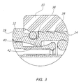
- FIG. 3 is an enlarged view of the connection between the PTC connector and the component.
- FIGS. 1 and 2 illustrate a pneumatic device assembly 10, in which a Push To Connect (PCT) fitting cartridge 12 is illustrated.
- PCT cartridge 12 is insertable into port 14 of pneumatic device 16, which may include, for example, a pneumatic brake and a pneumatic height control valve.
- the PCT cartridge 12 is provided having a generally cylindrical diameter, but may, be provided with virtually any type of cross-section.
- PCT cartridge 12 is illustrated in FIG. 1 generally having a cross-section diameter (d).
- PCT cartridge 12 is further illustrated in FIG. 1 having a cartridge shoulder 28, which is defined having a cross-section diameter (d 1 ).
- cartridge shoulder 28 extends out beyond outer surface 26 of the PCT cartridge 12, such that, diameter (d 1 ) is larger than diameter (d).
- PCT cartridge 12 is further illustrated having a tube 18 connection, which is illustrated in FIGS. 1 and 2.
- Tube 18 may couple to PCT cartridge 12 by means of a tube cavity 20, which extends from a distal end 22 of PCT cartridge 12.
- Tube cavity 20 is provided for receiving pneumatic tube 18 therein, the tube 18 coupled to the port 14 via the PCT cartridge 12.
- Tube 18 is provided such that, pressurized air may be selectively introduced and/or exhausted from the pneumatic device 16 via the tube 18.
- port 14 is provided having a generally cylindrical diameter and is provided with an inner surface 24 that is designed to receive outer surface 26 of the PCT cartridge 12 in relatively close fit.
- the inner surface 24 of port 14 is illustrated having a cross-section diameter (d 2 ).
- Port 14 is further provided with a port shoulder 30, which is designed to abut cartridge shoulder 28 of PCT cartridge 12 as shown.
- port shoulder 30 is provided with a beveled section 32 to simplify the insertion of PCT cartridge 12.
- Port shoulder 30 is provided such that, when PCT cartridge 12 is inserted therein, PCT cartridge 12 is steadied and securely maintained therein.
- Cartridge shoulder 28 is also provided as a stop for PCT cartridge 12 when cartridge shoulder 28 abuts up against port shoulder 30.
- the cross-section diameter (d 1 ) of cartridge shoulder 28 is larger than the cross-section diameter (d 2 ) of the inner surface 24 of port 14.
- tube 18 may be inserted in to tube cavity 20 via tube cavity opening 34.
- Tube cavity opening 34 is indicated as having an opening with a cross-section diameter (d 3 ), while tube cavity is shown having a cross-section diameter (d 4 ), where diameter (d 3 ) is larger than diameter (d 4 ).
- tube 18 encounters a beveled edge at tube cavity opening 34 to facilitate insertion of tube 18 in cavity opening 34.
- FIG. 3 an enlarged view of a section of FIG. 2 is illustrated, which shows PCT cartridge 12 inserted in port 14, and more particularly, the interaction of PCT cartridge 12 with the inner surface 24 of port 14.
- outer surface 26 of the PCT cartridge 12 is provided with protrusion(s) 36, which in this embodiment are provided as teeth to engage with inner surface 24.
- undercut 38 which is situated on inner surface 24 of port 14.
- Undercut 38 is provided to engage with protrusion(s) 36 such that, upon advancement of PCT cartridge 12 into port 14, a snap fit occurs and an interlock is developed.
- the cross-section diameter (d) of PCT cartridge 12 is provided slightly larger than the cross-section diameter (d 2 ) of the inner surface 24. Therefore, advancement of PCT cartridge 12 into port 14 will generate "hoop" stress on the surrounding material as the protrusion(s) 36 are slightly deflected radially inward. However, as the protrusion(s) 36 advance past undercut 38, the protrusion(s) 36 is then able to expand radially outward again thereby reliving any "hoop" stress temporarily encountered by port 14.
- O-ring 40 is provided in a channel 42, which is positioned between the inner surface 24 and the PCT cartridge 12. In this manner an air-tight seal may be created between PCT cartridge 12 and port 14. It is contemplated that O-ring 40 may comprise any type of material as desired for the application, but typically will comprise a pliable elastic material, such as , for example, rubber.
- detaching means are provided in the form of cartridge shoulder 28, which may be deflected radially inward to as to disengage protrusion(s) 36 from undercut 38. In this manner, PCT cartridge 12 may then be easily withdrawn from port 14.
- a highly engineered grade plastic PTC fitting cartridge may effectively be used for connection of air tubes or conduits to an air brake or height control valve. Therefore, the present system allows for the speed and convenience of PTC fittings to be taken advantage of, while at the same time, any stress encountered by the surrounding material is substantially eliminated to avoid fracture of the surrounding material.
Landscapes
- Engineering & Computer Science (AREA)
- General Engineering & Computer Science (AREA)
- Mechanical Engineering (AREA)
- Transportation (AREA)
- Valves And Accessory Devices For Braking Systems (AREA)
- Quick-Acting Or Multi-Walled Pipe Joints (AREA)
- Earth Drilling (AREA)
- Medicines Containing Plant Substances (AREA)
- Enzymes And Modification Thereof (AREA)
- Braking Systems And Boosters (AREA)
Abstract
Description
- The invention relates to a Push To Connect (PTC) fitting cartridge used in a pneumatic device, and more specifically to a high strength plastic PTC cartridge attached to a housing of a pneumatic device, the system substantially eliminating stress on the housing due to the PTC cartridge.
- Pneumatic devices, such as, air brakes and height control valves, such as are used on heavy equipment, have been in use for many years. Pneumatic devices typically utilize a number of pneumatic lines, which must be connected and interconnected to the various devices. The pneumatic device typically comprises a housing to which a number of components may be connected. The housing is provided with a number of openings for receiving various connections and component connections.
- Numerous types of connectors may be connected to the housing and may include, for example, threaded connectors, friction connectors and so forth. Push To Connect (PTC) fittings may also be used with various types of housing configurations. PTC fittings present a number of distinct advantages over other types of connectors. For instance, it is a relatively simple matter to connect pneumatic tubing with a PCT fitting as one simply needs to push the connector into a port, where the connector is retained by an interference fit.
- Typically, PTC fittings are provided manufactured of a relatively hard plastic. The plastic is typically a highly engineered grade, having high strength characteristics. This means that the plastic material will have relatively little "give" as very high strength characteristics are advantageous for critical applications, such as, vehicle braking and vehicle ride height control.
- The pneumatic device housing may also be provided with a highly engineered grade plastic port for receiving the plastic connector. In addition, various portions of the housing may comprise a highly engineered grade plastic with relatively high strength characteristics. Interference fit connectors, such as a PTC fitting, introduce stress to the surrounding material as the introduced stress between the connector and the port, maintains the connection.
- However, a problem arises in particular with vehicle air brake and vehicle control valve applications, in part, due to the required relatively high strength characteristics of the PTC fitting. The press fit induces "hoop" stress in the port and subsequently the housing, which often results in fracturing in the surrounding material. Any fracturing of the surrounding material can result in loosening of the connection and/or catastrophic failure of the braking and/or height control system. Any failure of vehicle safety systems is unacceptable.
- Therefore, what is desired is a PTC fitting manufactured of a highly engineered grade plastic having high strength characteristics for use in a vehicle air brake and/or height control system that substantially eliminates fracturing in the surrounding material due to introduced stress.
- It is still further desired to provide highly reliable vehicle air brake and/or height control system that uses a PTC fitting manufactured of a highly engineered grade plastic having high strength characteristics that is received in a port of the pneumatic device.
- These and other objectives are achieved in one advantageous embodiment, by the provision of a PTC fitting cartridge manufactured of a highly engineered grade plastic having high strength characteristics used in a vehicle air brake and/or height control system, which when advanced into a component, interconnects with an undercut provided in the surrounding material to substantially eliminate any "hoop" stress to avoid any fracturing of the surrounding material.
- In this manner, rather that utilize the standard interference fitting, the PTC fitting cartridge of the present invention uses a snap fit for retention in the air brake housing or the height control valve housing. The highly engineered grade plastic PTC fitting cartridge will initially deflect radially inward upon advancement into the connector. The exterior of the PTC connector is provided with at least one protrusion that upon advancement of the protrusion past the undercut re-expands radially outward to interact with the undercut. In this manner, any "hoop" stress that may initially be experienced by the surrounding material upon advancement of the PTC fitting cartridge into the port, is only temporary because the PTC fitting cartridge is allowed to re-expand to its normal shape past the undercut.
- As the protrusion(s) interacts with the undercut forming an interlock between the PTC fitting cartridge and the port, the PTC fitting cartridge is securely maintained or locked into the port. Therefore, the convenience of using a PTC fitting cartridge manufactured of a highly engineered grade plastic having high strength characteristics may be used in connection with a vehicle brake housing or a height control valve housing, while still not compromising the integrity of the pneumatic vehicle system.
- It is contemplated that the PTC fitting cartridge may further be provided with means for removing the PTC fitting cartridge from the port. This may include, for example, means for disengaging the protrusion(s) from the undercut, such as deflection of the protrusion(s) radially inwardly so that the PTC fitting cartridge may be withdrawn from the port. For example, the PTC fitting cartridge may be provided with a shoulder on either side of the PTC fitting cartridge to which inward pressure may be applied to deflect the protrusion(s) inwardly. In this manner, the PTC fitting cartridge may then be unlocked from the port and then withdrawn from the housing.
- In one advantageous embodiment, a pneumatic device assembly is provided, comprising a housing for the pneumatic device, where the housing has a port located therein. The pneumatic device assembly further comprises a push to connect fitting cartridge receivable in the port, where the push to connect fitting cartridge comprises plastic and includes at least one protrusion located on an outer surface thereof. The pneumatic device assembly is provided such that the port has an undercut located on an inner surface thereof for receiving the protrusion to create an interlock between the push to connect fitting cartridge and the housing, and the pneumatic device is selected from the group consisting of: a pneumatic brake and a pneumatic height control valve.
- In another advantageous embodiment, a method for connecting a push to connect fitting cartridge to a pneumatic brake or a pneumatic height control valve is provided, comprising the steps of positioning a protrusion on an outer surface of a plastic push to connect fitting cartridge, and positioning a port in a housing of the pneumatic brake or a pneumatic height control valve for receiving the plastic push to connect fitting cartridge therein. The method further comprises the steps of forming an undercut in an inner surface of the port, inserting the plastic push to connect fitting cartridge into the port, and forming an interlock between the push to connect fitting cartridge and the port through the interaction of the protrusion with the undercut.
- In still another advantageous embodiment, a pneumatic device assembly is provided, comprising a housing for the pneumatic device, where the housing having a port located therein, and the port has an inner surface with a cross section diameter of (d2). The port also includes an undercut located on the inner surface, with the undercut having a cross section diameter of (d4), where diameter (d2) is smaller than diameter (d4). The pneumatic device assembly further comprises a push to connect fitting cartridge receivable in the port, where the push to connect fitting cartridge comprises plastic and includes at least one protrusion located on an outer surface thereof. The pneumatic device assembly is provided such that the protrusion, upon advancement of the push to connect fitting cartridge into the port, interacts with the undercut to form an interlock, and the pneumatic device is selected from the group consisting of: a pneumatic brake and a pneumatic height control valve.
- Other objects of the invention and its particular features and advantages will become more apparent from consideration of the following drawings and accompanying detailed description.
- FIG. 1 is an illustration of a PTC cartridge to be inserted into a housing of a pneumatic device.
- FIG. 2 is an illustration of the PTC cartridge according to FIG. 1 inserted into the housing of the pneumatic device.
- FIG. 3 is an enlarged view of the connection between the PTC connector and the component.
- Referring now to the drawings, wherein like reference numerals designate corresponding structure throughout the views.
- FIGS. 1 and 2 illustrate a
pneumatic device assembly 10, in which a Push To Connect (PCT)fitting cartridge 12 is illustrated. As seen in FIG. 1,PCT cartridge 12 is insertable intoport 14 ofpneumatic device 16, which may include, for example, a pneumatic brake and a pneumatic height control valve. - The
PCT cartridge 12 is provided having a generally cylindrical diameter, but may, be provided with virtually any type of cross-section. PCTcartridge 12 is illustrated in FIG. 1 generally having a cross-section diameter (d). - PCT
cartridge 12 is further illustrated in FIG. 1 having acartridge shoulder 28, which is defined having a cross-section diameter (d1). As can be seen in FIG. 1,cartridge shoulder 28 extends out beyondouter surface 26 of thePCT cartridge 12, such that, diameter (d1) is larger than diameter (d). -
PCT cartridge 12 is further illustrated having atube 18 connection, which is illustrated in FIGS. 1 and 2. Tube 18 may couple toPCT cartridge 12 by means of atube cavity 20, which extends from adistal end 22 ofPCT cartridge 12.Tube cavity 20 is provided for receivingpneumatic tube 18 therein, thetube 18 coupled to theport 14 via thePCT cartridge 12. Tube 18 is provided such that, pressurized air may be selectively introduced and/or exhausted from thepneumatic device 16 via thetube 18. - Referring now to
port 14 ofpneumatic device 16,port 14 is provided having a generally cylindrical diameter and is provided with aninner surface 24 that is designed to receiveouter surface 26 of thePCT cartridge 12 in relatively close fit. Theinner surface 24 ofport 14 is illustrated having a cross-section diameter (d2). - In this manner, it is a relatively simple matter to insert
PCT cartridge 12 intoport 14 tocouple tube 18 topneumatic device 16 as is illustrated in FIG. 2. -
Port 14 is further provided with aport shoulder 30, which is designed to abutcartridge shoulder 28 ofPCT cartridge 12 as shown. As can be seen,port shoulder 30 is provided with abeveled section 32 to simplify the insertion ofPCT cartridge 12. -
Port shoulder 30 is provided such that, whenPCT cartridge 12 is inserted therein,PCT cartridge 12 is steadied and securely maintained therein.Cartridge shoulder 28 is also provided as a stop forPCT cartridge 12 whencartridge shoulder 28 abuts up againstport shoulder 30. As can be seen, the cross-section diameter (d1) ofcartridge shoulder 28 is larger than the cross-section diameter (d2) of theinner surface 24 ofport 14. - As seen in FIG. 2,
tube 18 may be inserted in totube cavity 20 viatube cavity opening 34. Tube cavity opening 34 is indicated as having an opening with a cross-section diameter (d3), while tube cavity is shown having a cross-section diameter (d4), where diameter (d3) is larger than diameter (d4). In this manner,tube 18 encounters a beveled edge at tube cavity opening 34 to facilitate insertion oftube 18 incavity opening 34. - Referring now to FIG. 3, an enlarged view of a section of FIG. 2 is illustrated, which shows
PCT cartridge 12 inserted inport 14, and more particularly, the interaction ofPCT cartridge 12 with theinner surface 24 ofport 14. - As shown in FIG. 3,
outer surface 26 of thePCT cartridge 12 is provided with protrusion(s) 36, which in this embodiment are provided as teeth to engage withinner surface 24. Also illustrated in FIG. 3 is undercut 38, which is situated oninner surface 24 ofport 14. Undercut 38 is provided to engage with protrusion(s) 36 such that, upon advancement ofPCT cartridge 12 intoport 14, a snap fit occurs and an interlock is developed. For example, the cross-section diameter (d) ofPCT cartridge 12 is provided slightly larger than the cross-section diameter (d2) of theinner surface 24. Therefore, advancement ofPCT cartridge 12 intoport 14 will generate "hoop" stress on the surrounding material as the protrusion(s) 36 are slightly deflected radially inward. However, as the protrusion(s) 36 advance past undercut 38, the protrusion(s) 36 is then able to expand radially outward again thereby reliving any "hoop" stress temporarily encountered byport 14. - It may also be seen from FIG. 3, that an O-
ring 40 is provided in achannel 42, which is positioned between theinner surface 24 and thePCT cartridge 12. In this manner an air-tight seal may be created betweenPCT cartridge 12 andport 14. It is contemplated that O-ring 40 may comprise any type of material as desired for the application, but typically will comprise a pliable elastic material, such as , for example, rubber. - It can be seen from FIG. 3 that the interlock created between
PCT cartridge 12 andport 14 creates a highly secure connection, which will not easily be interrupted. This is very advantageous as the coupling will not loosen or disconnect due to, for example, vibration. - It may however, become necessary to disconnect
PCT cartridge 12 for servicing, replacement, etc. As an interlock has been created betweenPCT cartridge 12 andport 14, simply applying withdrawing pressure may not detach thePCT cartridge 12 fromport 14. Accordingly, detaching means are provided in the form ofcartridge shoulder 28, which may be deflected radially inward to as to disengage protrusion(s) 36 from undercut 38. In this manner,PCT cartridge 12 may then be easily withdrawn fromport 14. - In this manner, a highly engineered grade plastic PTC fitting cartridge may effectively be used for connection of air tubes or conduits to an air brake or height control valve. Therefore, the present system allows for the speed and convenience of PTC fittings to be taken advantage of, while at the same time, any stress encountered by the surrounding material is substantially eliminated to avoid fracture of the surrounding material.
- Although the invention has been described with reference to a particular arrangement of parts, features and the like, these are not intended to exhaust all possible arrangements or features, and indeed many other modifications and variations will be ascertainable to those of skill in the art.
Claims (20)
- A pneumatic device assembly comprising:a housing for the pneumatic device;said housing having a port located therein;a push to connect fitting cartridge receivable in said port;said push to connect fitting cartridge comprising plastic and including at least one protrusion located on an outer surface thereof;said port having an undercut located on an inner surface thereof for receiving said protrusion to create an interlock between said push to connect fitting cartridge and said housing; andsaid pneumatic device is selected from the group consisting of: a pneumatic brake and a pneumatic height control valve.
- The pneumatic device assembly according to Claim 1 wherein said protrusion comprises a plurality of protrusions.
- The pneumatic device assembly according to Claim 2 wherein said plurality of protrusions comprise teeth.
- The pneumatic device assembly according to Claim 1 wherein said push to connect fitting cartridge further comprises an O-ring positioned on the outer surface of said push to connect fitting cartridge.
- The pneumatic device assembly according to Claim 1 wherein said O-ring is positioned in a channel located in the outer surface of said push to connect fitting cartridge.
- The pneumatic device assembly according to Claim 1 wherein said push to connect fitting cartridge further comprises a cartridge shoulder.
- The pneumatic device assembly according to Claim 6 wherein said shoulder may be deflected inward relative to said push to connect fitting cartridge such that said protrusion is deflected radially inward from said undercut for removal of said push to connect fitting cartridge from said port.
- The pneumatic device assembly according to Claim 6 wherein said outer surface of said push to connect fitting cartridge has a cross-section diameter (d) and said cartridge shoulder has a cross-section diameter (d1), where diameter (d1) is larger than diameter (d).
- The pneumatic device assembly according to Claim 8 wherein said port further comprises a port shoulder against which said cartridge shoulder abuts when said push to connect fitting cartridge is inserted into said port.
- The pneumatic device assembly according to Claim 9 wherein said port shoulder has an inner cross-section diameter (d2), wherein diameter (d1) is larger than diameter (d2).
- The pneumatic device assembly according to Claim 1 wherein said push to connect fitting cartridge comprises a tube cavity having a tube cavity opening for receiving a pneumatic tube therein, the tube coupled to said port via said push to connect fitting cartridge.
- The pneumatic device assembly according to Claim 11 wherein pressurized air is selectively introduced and/or exhausted from said pneumatic device via said tube.
- The pneumatic device assembly according to Claim 11 wherein said tube cavity opening has a cross-section diameter (d3) and an inner surface of the tube cavity has a cross-section diameter (d4), where diameter (d3) is larger than diameter (d4).
- A method for connecting a push to connect fitting cartridge to a pneumatic brake or a pneumatic height control valve comprising the steps of:positioning a protrusion on an outer surface of a plastic push to connect fitting cartridge;positioning a port in a housing of the pneumatic brake or a pneumatic height control valve for receiving the plastic push to connect fitting cartridge therein;forming an undercut in an inner surface of the port;inserting the plastic push to connect fitting cartridge into the port; andforming an interlock between the push to connect fitting cartridge and the port through the interaction of the protrusion with the undercut.
- The method according to Claim 14 wherein the protrusion comprises a plurality of protrusions.
- The method according to Claim 15 wherein the plurality of protrusions comprise teeth.
- The method according to Claim 14 further comprising the step of positioning a cartridge shoulder on the push to connect fitting cartridge, which abuts a port shoulder when said push to connect fitting cartridge is inserted into said port.
- The method according to Claim 17 further comprising the steps of:deflecting the cartridge shoulder inwardly to disengage the protrusion from the undercut; andwithdrawing the push to connect fitting cartridge from the port.
- The method according to Claim 14 further comprising the steps of:positioning a tube in a tube connection opening at a distal end of the push to connect fitting cartridge to couple the tube to the port; andselectively introducing and/or exhausting air from the pneumatic brake or a pneumatic height control valve via the tube.
- A pneumatic device assembly comprising:a housing for the pneumatic device;said housing having a port located therein;said port having an inner surface with a cross section diameter of (d2);said port including an undercut located on the inner surface, the undercut having a cross section diameter of (d4), where diameter (d2) is smaller than diameter (d4);a push to connect fitting cartridge receivable in said port;said push to connect fitting cartridge comprising plastic and including at least one protrusion located on an outer surface thereof;said protrusion, upon advancement of said push to connect fitting cartridge into said port, interacting with said undercut to form an interlock; andsaid pneumatic device is selected from the group consisting of: a pneumatic brake and a pneumatic height control valve.
Applications Claiming Priority (1)
| Application Number | Priority Date | Filing Date | Title |
|---|---|---|---|
| US11/484,448 US7908730B2 (en) | 2006-07-11 | 2006-07-11 | PTC fitting cartridge |
Publications (2)
| Publication Number | Publication Date |
|---|---|
| EP1878962A1 true EP1878962A1 (en) | 2008-01-16 |
| EP1878962B1 EP1878962B1 (en) | 2010-12-15 |
Family
ID=38578420
Family Applications (1)
| Application Number | Title | Priority Date | Filing Date |
|---|---|---|---|
| EP07110041A Not-in-force EP1878962B1 (en) | 2006-07-11 | 2007-06-12 | PTC fitting cartridge |
Country Status (11)
| Country | Link |
|---|---|
| US (2) | US7908730B2 (en) |
| EP (1) | EP1878962B1 (en) |
| JP (1) | JP4705073B2 (en) |
| KR (1) | KR100881677B1 (en) |
| CN (1) | CN101105255B (en) |
| AT (1) | ATE491908T1 (en) |
| AU (1) | AU2007201899B2 (en) |
| BR (1) | BRPI0702813A (en) |
| DE (1) | DE602007011159D1 (en) |
| HK (1) | HK1111755A1 (en) |
| RU (1) | RU2379204C2 (en) |
Cited By (4)
| Publication number | Priority date | Publication date | Assignee | Title |
|---|---|---|---|---|
| WO2011000766A1 (en) * | 2009-06-29 | 2011-01-06 | Knorr-Bremse Systeme für Nutzfahrzeuge GmbH | Air dryer cartridge for a compressed air treatment system of a vehicle |
| US7908730B2 (en) | 2006-07-11 | 2011-03-22 | Haldex Brake Corporation | PTC fitting cartridge |
| EP2990280A1 (en) * | 2014-08-29 | 2016-03-02 | Haldex Brake Products GmbH | Assembly with a fluid line and a coupling head |
| EP3090909A1 (en) * | 2015-05-04 | 2016-11-09 | Haldex Brake Products GmbH | Fluidic connector plug |
Families Citing this family (4)
| Publication number | Priority date | Publication date | Assignee | Title |
|---|---|---|---|---|
| US20080231048A1 (en) * | 2007-03-22 | 2008-09-25 | Norgren, Inc. | Pneumatic swivel elbow |
| DE102007027148A1 (en) * | 2007-06-13 | 2008-12-18 | Knorr-Bremse Systeme für Nutzfahrzeuge GmbH | Releasable pneumatic connection |
| KR20170084951A (en) * | 2016-01-13 | 2017-07-21 | 삼성전자주식회사 | Light Deflector and Display Device |
| CN117006340B (en) * | 2023-10-07 | 2024-01-09 | 山东华翼绿色生态发展有限公司 | Pipe fitting connecting equipment for installation of vertical ground source heat pump deep well |
Citations (6)
| Publication number | Priority date | Publication date | Assignee | Title |
|---|---|---|---|---|
| GB1436734A (en) * | 1973-06-27 | 1976-05-26 | Enots Ltd | Releasable couplings for tubes |
| EP0733844A2 (en) * | 1995-03-21 | 1996-09-25 | Armaturenfabrik Hermann Voss GmbH + Co. | Conduit connection device |
| US6224117B1 (en) * | 1998-10-05 | 2001-05-01 | Dana Corporation | Contaminant resistant tube fitting |
| DE20214847U1 (en) * | 2002-09-24 | 2004-02-19 | Voss Automotive Gmbh | Connection device for pipes |
| DE20319959U1 (en) * | 2003-12-23 | 2005-05-04 | Voss Automotive Gmbh | Connectors for media cables |
| WO2006037967A1 (en) * | 2004-10-01 | 2006-04-13 | Norgren Limited | Seals |
Family Cites Families (23)
| Publication number | Priority date | Publication date | Assignee | Title |
|---|---|---|---|---|
| US3761117A (en) * | 1972-04-19 | 1973-09-25 | Crawford Fitting Co | Quick connect fitting |
| US3773360A (en) * | 1972-09-01 | 1973-11-20 | W Timbers | Quick disconnect coupling |
| US4685706A (en) * | 1985-03-04 | 1987-08-11 | Clevite Industries Inc. | Releasable push-to-connect tube fitting |
| US4664427A (en) * | 1985-04-01 | 1987-05-12 | Master Industries, Inc. | Quick connect fitting |
| US5143347A (en) * | 1992-01-14 | 1992-09-01 | Lee Yeong D | Revolvable quick coupling |
| US5429394A (en) | 1993-11-15 | 1995-07-04 | Dana Corporation | Quick connect cartridge assembly with plug |
| US5468028A (en) * | 1994-12-19 | 1995-11-21 | Dana Corporation | Quick connect tube couplings |
| JPH09303655A (en) * | 1996-05-20 | 1997-11-28 | Sekisui Chem Co Ltd | Pipe joint with collet |
| JP2000088166A (en) | 1998-09-18 | 2000-03-31 | Taiyo Ltd | Coupling for pneumatic piping |
| JP2000274576A (en) * | 1999-03-24 | 2000-10-03 | Toyoda Gosei Co Ltd | Hose connecting structure and hose |
| US6588805B2 (en) * | 2000-10-03 | 2003-07-08 | Eaton Aeroquip, Inc. | Coupling adapter and assembly |
| EP1373040B1 (en) * | 2001-03-21 | 2010-04-28 | Continental Teves AG & Co. oHG | Brake servo comprising a connecting element with a defined angular position |
| US6880587B1 (en) * | 2002-02-23 | 2005-04-19 | Precision Thermoplastic Components, Inc. | Refrigerant material transfer device and method |
| JP3988181B2 (en) * | 2002-03-15 | 2007-10-10 | 東海ゴム工業株式会社 | Tube fitting |
| US6637781B1 (en) * | 2002-10-07 | 2003-10-28 | International Engine Intellectual Property Company, L.L.C. | Coupling |
| NO20025234L (en) * | 2002-10-31 | 2004-05-03 | Raufoss United As | Coupling part with male part, for use in a flowing fluid system |
| DE502004006723D1 (en) * | 2003-06-23 | 2008-05-15 | Lincoln Gmbh | CONNECTION DEVICE FOR A TUBE OR DGL |
| KR200335339Y1 (en) | 2003-09-01 | 2003-12-06 | 이승만 | A coupling device for atmospheric pressure tube and oil pressure tube of solenoid valve |
| WO2005057075A1 (en) | 2003-12-04 | 2005-06-23 | Eaton Corporation | Quick-connect cartridge assembly with plug |
| WO2006033815A1 (en) * | 2004-09-17 | 2006-03-30 | The Gates Corporation | Quick connect coupling |
| US7963570B2 (en) * | 2005-09-01 | 2011-06-21 | The Gates Corporation | Quick connect coupling stabilization apparatus, systems and methods |
| US7908730B2 (en) | 2006-07-11 | 2011-03-22 | Haldex Brake Corporation | PTC fitting cartridge |
| US20080265565A1 (en) * | 2007-04-26 | 2008-10-30 | Comdel Innovations Inc. | Suction coupling system and assembly |
-
2006
- 2006-07-11 US US11/484,448 patent/US7908730B2/en not_active Expired - Fee Related
-
2007
- 2007-04-30 AU AU2007201899A patent/AU2007201899B2/en not_active Ceased
- 2007-04-30 KR KR1020070041910A patent/KR100881677B1/en not_active IP Right Cessation
- 2007-05-17 RU RU2007118454/11A patent/RU2379204C2/en not_active IP Right Cessation
- 2007-06-12 EP EP07110041A patent/EP1878962B1/en not_active Not-in-force
- 2007-06-12 DE DE602007011159T patent/DE602007011159D1/en active Active
- 2007-06-12 AT AT07110041T patent/ATE491908T1/en not_active IP Right Cessation
- 2007-06-25 JP JP2007166697A patent/JP4705073B2/en not_active Expired - Fee Related
- 2007-07-09 BR BRPI0702813-0A patent/BRPI0702813A/en not_active Application Discontinuation
- 2007-07-11 CN CN2007101291112A patent/CN101105255B/en not_active Expired - Fee Related
-
2008
- 2008-03-04 HK HK08102459.2A patent/HK1111755A1/en not_active IP Right Cessation
-
2011
- 2011-02-22 US US13/031,998 patent/US8991023B2/en not_active Expired - Fee Related
Patent Citations (6)
| Publication number | Priority date | Publication date | Assignee | Title |
|---|---|---|---|---|
| GB1436734A (en) * | 1973-06-27 | 1976-05-26 | Enots Ltd | Releasable couplings for tubes |
| EP0733844A2 (en) * | 1995-03-21 | 1996-09-25 | Armaturenfabrik Hermann Voss GmbH + Co. | Conduit connection device |
| US6224117B1 (en) * | 1998-10-05 | 2001-05-01 | Dana Corporation | Contaminant resistant tube fitting |
| DE20214847U1 (en) * | 2002-09-24 | 2004-02-19 | Voss Automotive Gmbh | Connection device for pipes |
| DE20319959U1 (en) * | 2003-12-23 | 2005-05-04 | Voss Automotive Gmbh | Connectors for media cables |
| WO2006037967A1 (en) * | 2004-10-01 | 2006-04-13 | Norgren Limited | Seals |
Cited By (8)
| Publication number | Priority date | Publication date | Assignee | Title |
|---|---|---|---|---|
| US7908730B2 (en) | 2006-07-11 | 2011-03-22 | Haldex Brake Corporation | PTC fitting cartridge |
| US8991023B2 (en) | 2006-07-11 | 2015-03-31 | Haldex Brake Corporation | PTC fitting cartridge |
| WO2011000766A1 (en) * | 2009-06-29 | 2011-01-06 | Knorr-Bremse Systeme für Nutzfahrzeuge GmbH | Air dryer cartridge for a compressed air treatment system of a vehicle |
| CN102448783A (en) * | 2009-06-29 | 2012-05-09 | 克诺尔商用车制动系统有限公司 | Air dryer cartridge for a compressed air treatment system of a vehicle |
| US8657939B2 (en) | 2009-06-29 | 2014-02-25 | Knorr-Bremse Systeme Fuer Nutzfahrzeuge Gmbh | Air dryer cartridge for a compressed air treatment system of a vehicle |
| RU2532035C2 (en) * | 2009-06-29 | 2014-10-27 | Кнорр-Бремзе Зюстеме Фюр Нутцфарцойге Гмбх | Moisture trap cartridge for vehicle compressed air preparation device |
| EP2990280A1 (en) * | 2014-08-29 | 2016-03-02 | Haldex Brake Products GmbH | Assembly with a fluid line and a coupling head |
| EP3090909A1 (en) * | 2015-05-04 | 2016-11-09 | Haldex Brake Products GmbH | Fluidic connector plug |
Also Published As
| Publication number | Publication date |
|---|---|
| US20080012318A1 (en) | 2008-01-17 |
| JP4705073B2 (en) | 2011-06-22 |
| JP2008020067A (en) | 2008-01-31 |
| KR20080006445A (en) | 2008-01-16 |
| US8991023B2 (en) | 2015-03-31 |
| HK1111755A1 (en) | 2008-08-15 |
| BRPI0702813A (en) | 2008-02-26 |
| CN101105255B (en) | 2011-08-17 |
| RU2379204C2 (en) | 2010-01-20 |
| US20110140414A1 (en) | 2011-06-16 |
| KR100881677B1 (en) | 2009-02-06 |
| RU2007118454A (en) | 2008-11-27 |
| CN101105255A (en) | 2008-01-16 |
| AU2007201899A1 (en) | 2008-01-31 |
| US7908730B2 (en) | 2011-03-22 |
| AU2007201899B2 (en) | 2009-11-12 |
| ATE491908T1 (en) | 2011-01-15 |
| EP1878962B1 (en) | 2010-12-15 |
| DE602007011159D1 (en) | 2011-01-27 |
Similar Documents
| Publication | Publication Date | Title |
|---|---|---|
| US8991023B2 (en) | PTC fitting cartridge | |
| US7467813B2 (en) | Quick connector | |
| US5586792A (en) | Quick connector with integral release mechanism | |
| EP2204599B1 (en) | Quick connector for high pressure applications | |
| US7891380B2 (en) | Protective cap for quick connector | |
| EP1688197A2 (en) | Resin tube joint with reinforcing ring | |
| EP1818702A1 (en) | Improvements in or relating to tube couplings for connecting a pair of conduits for carrying a cable | |
| CN103026118A (en) | Single axis push to connect conduit fitting | |
| WO2007117688A2 (en) | Push-to-connect coupling for pressure applications | |
| CN103600740A (en) | Connecting device for media lines in region of wall duct, and wall element | |
| US7857360B2 (en) | Snap-in-place valved coupler | |
| CN111373185B (en) | Hose connector assembly | |
| EP1690033B1 (en) | Quick-connect cartridge assembly with plug | |
| EP2504613B1 (en) | Verification pin | |
| EP2160537B1 (en) | Detachable pneumatic connection | |
| KR20040045453A (en) | Connections | |
| EP2196718A1 (en) | Hose connection with vapour recovery | |
| CN110748727B (en) | Universal threadless connection | |
| CN115703221A (en) | Auxiliary installation tool, pipe connecting device and using method of pipe connecting device | |
| CN116066645A (en) | Push-in tube connector port | |
| HUT70814A (en) | Joint appliance | |
| WO2005071304A1 (en) | Fluid connectors | |
| WO2006106317A1 (en) | Tube coupling |
Legal Events
| Date | Code | Title | Description |
|---|---|---|---|
| PUAI | Public reference made under article 153(3) epc to a published international application that has entered the european phase |
Free format text: ORIGINAL CODE: 0009012 |
|
| 17P | Request for examination filed |
Effective date: 20070612 |
|
| AK | Designated contracting states |
Kind code of ref document: A1 Designated state(s): AT BE BG CH CY CZ DE DK EE ES FI FR GB GR HU IE IS IT LI LT LU LV MC MT NL PL PT RO SE SI SK TR |
|
| AX | Request for extension of the european patent |
Extension state: AL BA HR MK YU |
|
| 17Q | First examination report despatched |
Effective date: 20080327 |
|
| AKX | Designation fees paid |
Designated state(s): AT BE BG CH CY CZ DE DK EE ES FI FR GB GR HU IE IS IT LI LT LU LV MC MT NL PL PT RO SE SI SK TR |
|
| GRAJ | Information related to disapproval of communication of intention to grant by the applicant or resumption of examination proceedings by the epo deleted |
Free format text: ORIGINAL CODE: EPIDOSDIGR1 |
|
| GRAP | Despatch of communication of intention to grant a patent |
Free format text: ORIGINAL CODE: EPIDOSNIGR1 |
|
| GRAP | Despatch of communication of intention to grant a patent |
Free format text: ORIGINAL CODE: EPIDOSNIGR1 |
|
| GRAS | Grant fee paid |
Free format text: ORIGINAL CODE: EPIDOSNIGR3 |
|
| GRAA | (expected) grant |
Free format text: ORIGINAL CODE: 0009210 |
|
| AK | Designated contracting states |
Kind code of ref document: B1 Designated state(s): AT BE BG CH CY CZ DE DK EE ES FI FR GB GR HU IE IS IT LI LT LU LV MC MT NL PL PT RO SE SI SK TR |
|
| REG | Reference to a national code |
Ref country code: CH Ref legal event code: EP Ref country code: GB Ref legal event code: FG4D |
|
| REG | Reference to a national code |
Ref country code: IE Ref legal event code: FG4D |
|
| REF | Corresponds to: |
Ref document number: 602007011159 Country of ref document: DE Date of ref document: 20110127 Kind code of ref document: P |
|
| REG | Reference to a national code |
Ref country code: NL Ref legal event code: VDEP Effective date: 20101215 |
|
| PG25 | Lapsed in a contracting state [announced via postgrant information from national office to epo] |
Ref country code: LT Free format text: LAPSE BECAUSE OF FAILURE TO SUBMIT A TRANSLATION OF THE DESCRIPTION OR TO PAY THE FEE WITHIN THE PRESCRIBED TIME-LIMIT Effective date: 20101215 |
|
| LTIE | Lt: invalidation of european patent or patent extension |
Effective date: 20101215 |
|
| PG25 | Lapsed in a contracting state [announced via postgrant information from national office to epo] |
Ref country code: AT Free format text: LAPSE BECAUSE OF FAILURE TO SUBMIT A TRANSLATION OF THE DESCRIPTION OR TO PAY THE FEE WITHIN THE PRESCRIBED TIME-LIMIT Effective date: 20101215 Ref country code: LV Free format text: LAPSE BECAUSE OF FAILURE TO SUBMIT A TRANSLATION OF THE DESCRIPTION OR TO PAY THE FEE WITHIN THE PRESCRIBED TIME-LIMIT Effective date: 20101215 Ref country code: SE Free format text: LAPSE BECAUSE OF FAILURE TO SUBMIT A TRANSLATION OF THE DESCRIPTION OR TO PAY THE FEE WITHIN THE PRESCRIBED TIME-LIMIT Effective date: 20101215 Ref country code: CY Free format text: LAPSE BECAUSE OF FAILURE TO SUBMIT A TRANSLATION OF THE DESCRIPTION OR TO PAY THE FEE WITHIN THE PRESCRIBED TIME-LIMIT Effective date: 20101215 Ref country code: NL Free format text: LAPSE BECAUSE OF FAILURE TO SUBMIT A TRANSLATION OF THE DESCRIPTION OR TO PAY THE FEE WITHIN THE PRESCRIBED TIME-LIMIT Effective date: 20101215 Ref country code: SI Free format text: LAPSE BECAUSE OF FAILURE TO SUBMIT A TRANSLATION OF THE DESCRIPTION OR TO PAY THE FEE WITHIN THE PRESCRIBED TIME-LIMIT Effective date: 20101215 Ref country code: BG Free format text: LAPSE BECAUSE OF FAILURE TO SUBMIT A TRANSLATION OF THE DESCRIPTION OR TO PAY THE FEE WITHIN THE PRESCRIBED TIME-LIMIT Effective date: 20110315 Ref country code: FI Free format text: LAPSE BECAUSE OF FAILURE TO SUBMIT A TRANSLATION OF THE DESCRIPTION OR TO PAY THE FEE WITHIN THE PRESCRIBED TIME-LIMIT Effective date: 20101215 |
|
| PG25 | Lapsed in a contracting state [announced via postgrant information from national office to epo] |
Ref country code: ES Free format text: LAPSE BECAUSE OF FAILURE TO SUBMIT A TRANSLATION OF THE DESCRIPTION OR TO PAY THE FEE WITHIN THE PRESCRIBED TIME-LIMIT Effective date: 20110326 Ref country code: BE Free format text: LAPSE BECAUSE OF FAILURE TO SUBMIT A TRANSLATION OF THE DESCRIPTION OR TO PAY THE FEE WITHIN THE PRESCRIBED TIME-LIMIT Effective date: 20101215 Ref country code: GR Free format text: LAPSE BECAUSE OF FAILURE TO SUBMIT A TRANSLATION OF THE DESCRIPTION OR TO PAY THE FEE WITHIN THE PRESCRIBED TIME-LIMIT Effective date: 20110316 Ref country code: CZ Free format text: LAPSE BECAUSE OF FAILURE TO SUBMIT A TRANSLATION OF THE DESCRIPTION OR TO PAY THE FEE WITHIN THE PRESCRIBED TIME-LIMIT Effective date: 20101215 Ref country code: PT Free format text: LAPSE BECAUSE OF FAILURE TO SUBMIT A TRANSLATION OF THE DESCRIPTION OR TO PAY THE FEE WITHIN THE PRESCRIBED TIME-LIMIT Effective date: 20110415 Ref country code: EE Free format text: LAPSE BECAUSE OF FAILURE TO SUBMIT A TRANSLATION OF THE DESCRIPTION OR TO PAY THE FEE WITHIN THE PRESCRIBED TIME-LIMIT Effective date: 20101215 Ref country code: IS Free format text: LAPSE BECAUSE OF FAILURE TO SUBMIT A TRANSLATION OF THE DESCRIPTION OR TO PAY THE FEE WITHIN THE PRESCRIBED TIME-LIMIT Effective date: 20110415 |
|
| PG25 | Lapsed in a contracting state [announced via postgrant information from national office to epo] |
Ref country code: SK Free format text: LAPSE BECAUSE OF FAILURE TO SUBMIT A TRANSLATION OF THE DESCRIPTION OR TO PAY THE FEE WITHIN THE PRESCRIBED TIME-LIMIT Effective date: 20101215 Ref country code: PL Free format text: LAPSE BECAUSE OF FAILURE TO SUBMIT A TRANSLATION OF THE DESCRIPTION OR TO PAY THE FEE WITHIN THE PRESCRIBED TIME-LIMIT Effective date: 20101215 Ref country code: RO Free format text: LAPSE BECAUSE OF FAILURE TO SUBMIT A TRANSLATION OF THE DESCRIPTION OR TO PAY THE FEE WITHIN THE PRESCRIBED TIME-LIMIT Effective date: 20101215 |
|
| PLBE | No opposition filed within time limit |
Free format text: ORIGINAL CODE: 0009261 |
|
| STAA | Information on the status of an ep patent application or granted ep patent |
Free format text: STATUS: NO OPPOSITION FILED WITHIN TIME LIMIT |
|
| PG25 | Lapsed in a contracting state [announced via postgrant information from national office to epo] |
Ref country code: DK Free format text: LAPSE BECAUSE OF FAILURE TO SUBMIT A TRANSLATION OF THE DESCRIPTION OR TO PAY THE FEE WITHIN THE PRESCRIBED TIME-LIMIT Effective date: 20101215 |
|
| 26N | No opposition filed |
Effective date: 20110916 |
|
| PG25 | Lapsed in a contracting state [announced via postgrant information from national office to epo] |
Ref country code: MT Free format text: LAPSE BECAUSE OF FAILURE TO SUBMIT A TRANSLATION OF THE DESCRIPTION OR TO PAY THE FEE WITHIN THE PRESCRIBED TIME-LIMIT Effective date: 20101215 Ref country code: IT Free format text: LAPSE BECAUSE OF FAILURE TO SUBMIT A TRANSLATION OF THE DESCRIPTION OR TO PAY THE FEE WITHIN THE PRESCRIBED TIME-LIMIT Effective date: 20101215 |
|
| REG | Reference to a national code |
Ref country code: DE Ref legal event code: R097 Ref document number: 602007011159 Country of ref document: DE Effective date: 20110916 |
|
| REG | Reference to a national code |
Ref country code: CH Ref legal event code: PL |
|
| GBPC | Gb: european patent ceased through non-payment of renewal fee |
Effective date: 20110612 |
|
| REG | Reference to a national code |
Ref country code: FR Ref legal event code: ST Effective date: 20120229 |
|
| REG | Reference to a national code |
Ref country code: IE Ref legal event code: MM4A |
|
| REG | Reference to a national code |
Ref country code: DE Ref legal event code: R119 Ref document number: 602007011159 Country of ref document: DE Effective date: 20120103 |
|
| PG25 | Lapsed in a contracting state [announced via postgrant information from national office to epo] |
Ref country code: CH Free format text: LAPSE BECAUSE OF NON-PAYMENT OF DUE FEES Effective date: 20110630 Ref country code: IE Free format text: LAPSE BECAUSE OF NON-PAYMENT OF DUE FEES Effective date: 20110612 Ref country code: LI Free format text: LAPSE BECAUSE OF NON-PAYMENT OF DUE FEES Effective date: 20110630 Ref country code: FR Free format text: LAPSE BECAUSE OF NON-PAYMENT OF DUE FEES Effective date: 20110630 Ref country code: DE Free format text: LAPSE BECAUSE OF NON-PAYMENT OF DUE FEES Effective date: 20120103 |
|
| PG25 | Lapsed in a contracting state [announced via postgrant information from national office to epo] |
Ref country code: GB Free format text: LAPSE BECAUSE OF NON-PAYMENT OF DUE FEES Effective date: 20110612 |
|
| PG25 | Lapsed in a contracting state [announced via postgrant information from national office to epo] |
Ref country code: MC Free format text: LAPSE BECAUSE OF NON-PAYMENT OF DUE FEES Effective date: 20110630 |
|
| PG25 | Lapsed in a contracting state [announced via postgrant information from national office to epo] |
Ref country code: LU Free format text: LAPSE BECAUSE OF NON-PAYMENT OF DUE FEES Effective date: 20110612 |
|
| PG25 | Lapsed in a contracting state [announced via postgrant information from national office to epo] |
Ref country code: TR Free format text: LAPSE BECAUSE OF FAILURE TO SUBMIT A TRANSLATION OF THE DESCRIPTION OR TO PAY THE FEE WITHIN THE PRESCRIBED TIME-LIMIT Effective date: 20101215 |
|
| PG25 | Lapsed in a contracting state [announced via postgrant information from national office to epo] |
Ref country code: HU Free format text: LAPSE BECAUSE OF FAILURE TO SUBMIT A TRANSLATION OF THE DESCRIPTION OR TO PAY THE FEE WITHIN THE PRESCRIBED TIME-LIMIT Effective date: 20101215 |