EP2204599B1 - Quick connector for high pressure applications - Google Patents
Quick connector for high pressure applications Download PDFInfo
- Publication number
- EP2204599B1 EP2204599B1 EP10159861A EP10159861A EP2204599B1 EP 2204599 B1 EP2204599 B1 EP 2204599B1 EP 10159861 A EP10159861 A EP 10159861A EP 10159861 A EP10159861 A EP 10159861A EP 2204599 B1 EP2204599 B1 EP 2204599B1
- Authority
- EP
- European Patent Office
- Prior art keywords
- retainer
- ring
- locking arms
- legs
- extending
- Prior art date
- Legal status (The legal status is an assumption and is not a legal conclusion. Google has not performed a legal analysis and makes no representation as to the accuracy of the status listed.)
- Active
Links
- 238000003780 insertion Methods 0.000 claims abstract description 62
- 230000037431 insertion Effects 0.000 claims abstract description 62
- 239000012530 fluid Substances 0.000 claims abstract description 37
- 230000008878 coupling Effects 0.000 claims abstract description 35
- 238000010168 coupling process Methods 0.000 claims abstract description 35
- 238000005859 coupling reaction Methods 0.000 claims abstract description 35
- 238000007789 sealing Methods 0.000 claims abstract description 7
- 230000000295 complement effect Effects 0.000 claims description 4
- 125000006850 spacer group Chemical group 0.000 description 34
- 230000033001 locomotion Effects 0.000 description 5
- 241000272525 Anas platyrhynchos Species 0.000 description 4
- 239000000446 fuel Substances 0.000 description 3
- 210000004907 gland Anatomy 0.000 description 3
- 230000013011 mating Effects 0.000 description 3
- 239000004033 plastic Substances 0.000 description 3
- 230000000712 assembly Effects 0.000 description 2
- 238000000429 assembly Methods 0.000 description 2
- 230000004323 axial length Effects 0.000 description 2
- 239000000356 contaminant Substances 0.000 description 2
- 125000004122 cyclic group Chemical group 0.000 description 2
- 230000000694 effects Effects 0.000 description 2
- 239000000463 material Substances 0.000 description 2
- 239000002184 metal Substances 0.000 description 2
- 238000000034 method Methods 0.000 description 2
- 230000001681 protective effect Effects 0.000 description 2
- 238000012546 transfer Methods 0.000 description 2
- 241000405070 Percophidae Species 0.000 description 1
- 239000004809 Teflon Substances 0.000 description 1
- 229920006362 Teflon® Polymers 0.000 description 1
- 230000005540 biological transmission Effects 0.000 description 1
- 230000000903 blocking effect Effects 0.000 description 1
- 238000007664 blowing Methods 0.000 description 1
- 238000004891 communication Methods 0.000 description 1
- 230000006835 compression Effects 0.000 description 1
- 238000007906 compression Methods 0.000 description 1
- 230000001419 dependent effect Effects 0.000 description 1
- 238000009434 installation Methods 0.000 description 1
- 239000007788 liquid Substances 0.000 description 1
- 238000012986 modification Methods 0.000 description 1
- 230000004048 modification Effects 0.000 description 1
- 229920000642 polymer Polymers 0.000 description 1
- 230000002250 progressing effect Effects 0.000 description 1
- 230000010349 pulsation Effects 0.000 description 1
- 230000000717 retained effect Effects 0.000 description 1
- 238000012360 testing method Methods 0.000 description 1
- 238000012795 verification Methods 0.000 description 1
- 239000011800 void material Substances 0.000 description 1
Images

Classifications
-
- F—MECHANICAL ENGINEERING; LIGHTING; HEATING; WEAPONS; BLASTING
- F16—ENGINEERING ELEMENTS AND UNITS; GENERAL MEASURES FOR PRODUCING AND MAINTAINING EFFECTIVE FUNCTIONING OF MACHINES OR INSTALLATIONS; THERMAL INSULATION IN GENERAL
- F16L—PIPES; JOINTS OR FITTINGS FOR PIPES; SUPPORTS FOR PIPES, CABLES OR PROTECTIVE TUBING; MEANS FOR THERMAL INSULATION IN GENERAL
- F16L37/00—Couplings of the quick-acting type
- F16L37/08—Couplings of the quick-acting type in which the connection between abutting or axially overlapping ends is maintained by locking members
- F16L37/084—Couplings of the quick-acting type in which the connection between abutting or axially overlapping ends is maintained by locking members combined with automatic locking
- F16L37/098—Couplings of the quick-acting type in which the connection between abutting or axially overlapping ends is maintained by locking members combined with automatic locking by means of flexible hooks
- F16L37/0985—Couplings of the quick-acting type in which the connection between abutting or axially overlapping ends is maintained by locking members combined with automatic locking by means of flexible hooks the flexible hook extending radially inwardly from an outer part and engaging a bead, recess or the like on an inner part
- F16L37/0987—Couplings of the quick-acting type in which the connection between abutting or axially overlapping ends is maintained by locking members combined with automatic locking by means of flexible hooks the flexible hook extending radially inwardly from an outer part and engaging a bead, recess or the like on an inner part the flexible hook being progressively compressed by axial tensile loads acting on the coupling
-
- F—MECHANICAL ENGINEERING; LIGHTING; HEATING; WEAPONS; BLASTING
- F16—ENGINEERING ELEMENTS AND UNITS; GENERAL MEASURES FOR PRODUCING AND MAINTAINING EFFECTIVE FUNCTIONING OF MACHINES OR INSTALLATIONS; THERMAL INSULATION IN GENERAL
- F16L—PIPES; JOINTS OR FITTINGS FOR PIPES; SUPPORTS FOR PIPES, CABLES OR PROTECTIVE TUBING; MEANS FOR THERMAL INSULATION IN GENERAL
- F16L37/00—Couplings of the quick-acting type
- F16L37/08—Couplings of the quick-acting type in which the connection between abutting or axially overlapping ends is maintained by locking members
- F16L37/084—Couplings of the quick-acting type in which the connection between abutting or axially overlapping ends is maintained by locking members combined with automatic locking
- F16L37/091—Couplings of the quick-acting type in which the connection between abutting or axially overlapping ends is maintained by locking members combined with automatic locking by means of a ring provided with teeth or fingers
-
- F—MECHANICAL ENGINEERING; LIGHTING; HEATING; WEAPONS; BLASTING
- F16—ENGINEERING ELEMENTS AND UNITS; GENERAL MEASURES FOR PRODUCING AND MAINTAINING EFFECTIVE FUNCTIONING OF MACHINES OR INSTALLATIONS; THERMAL INSULATION IN GENERAL
- F16L—PIPES; JOINTS OR FITTINGS FOR PIPES; SUPPORTS FOR PIPES, CABLES OR PROTECTIVE TUBING; MEANS FOR THERMAL INSULATION IN GENERAL
- F16L37/00—Couplings of the quick-acting type
- F16L37/08—Couplings of the quick-acting type in which the connection between abutting or axially overlapping ends is maintained by locking members
-
- F—MECHANICAL ENGINEERING; LIGHTING; HEATING; WEAPONS; BLASTING
- F16—ENGINEERING ELEMENTS AND UNITS; GENERAL MEASURES FOR PRODUCING AND MAINTAINING EFFECTIVE FUNCTIONING OF MACHINES OR INSTALLATIONS; THERMAL INSULATION IN GENERAL
- F16L—PIPES; JOINTS OR FITTINGS FOR PIPES; SUPPORTS FOR PIPES, CABLES OR PROTECTIVE TUBING; MEANS FOR THERMAL INSULATION IN GENERAL
- F16L2201/00—Special arrangements for pipe couplings
- F16L2201/10—Indicators for correct coupling
Definitions
- This application relates to quick connector coupling assemblies for fluid systems, and more particularly to a quick connector for high pressure applications that releasably connects a male member formed at the end of a hollow tube to a hollow connector body.
- a quick connector coupling assembly is often utilized to provide a fluid connection between two components or conduits which generally include a male member, or tube, received and retained in a female connector body.
- Use of a quick connector is advantageous in that a sealed and secure fluid line may be established with minimum amount of time and expense.
- a retainer is often used to secure the male member within the connector body.
- One such type of retainer includes a plurality of locking members which extend between a radially enlarged upset formed on the male member and an annular face defined in the connector body. The abutment of the retainer with the upset of the male member at one end and the annular face of the connector body at the other end prevents the withdrawal of the male member from the connector body. This type of retainer is prevalent in the art and has proven effective in many fluid line applications.
- a seal member usually in the form of an O-ring seal, is used with a quick connector coupling to create a fluid tight seal between the male member and the connector body.
- the O-ring is located axially inwardly of the retainer and separated by an annular spacer slidably mounted on the male member. It is often held against axial load imparted by fluid pressure by a spacer that is press fit, or in a snap fit relation to the bore in which it is received. Since the retainer is somewhat flexible, and the O-ring is slidably linked with the retainer, the O-ring is able to slide slightly relative to the male member.
- quick connector assemblies are often used in applications where the components are subject to high temperature or pressure, as well as vibration and cyclic application of pressure. These conditions increase the difficulty of maintaining a fluid tight joint. In high pressure applications such as automotive brake systems, it is necessary to ensure that the axial force imparted to the components be reliably accommodated.
- This invention which is defined in claim 1, is directed to an improved form of insertion verifier/latch that serves the functions of providing verification of the complete insertion of the male member into the body of the connector assembly, and also provides a latching function to stabilize the locking arms of the tube retainer to suppress inward movement and increase overall burst pressure performance.
- the insertion verifier/latch also serves to close the entrance into the connector body to minimize entry of contaminants. Additional features of the invention are disclosed in the dependent claims.
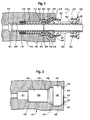
- FIG. 1 is a side sectional of the quick connector coupling assembly of the present invention with the tube releasably connected to the body component and the connection verifier positioned on the tube rearward of the tube upset.
- FIG. 2 is a sectional side view of the coupling receiving bore in the system component of the quick connector coupling assembly of FIG. 1 .
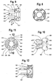
- FIG. 3 is a side view of the retainer of the present invention
- FIG. 4 is a plan view of the forward end of the retainer of FIG. 3 .
- FIG. 5 is a side sectional view of the retainer of FIG. 3 taken along the line 5-5 of FIG. 4 .
- FIG. 6 is a plan view of the rearward end of the retainer of FIG. 3 rotated forty-five degrees (45°) relative to FIG. 4 .
- FIG. 7 is a side view of the retainer of FIG. 6 .
- FIG. 8 is a plan view of the rearward end of the insertion verifier of the present invention.
- FIG. 9 is a side view of the insertion verifier of FIG. 8 .
- FIG. 10 is a side view of the insertion verifier of FIG. 8 rotated forty-five degrees (45°) relative to FIG. 9 .
- FIG. 11 is a plan view of the forward end of the insertion verifier of FIG. 8 .
- FIG. 12 is a side sectional view of the insertion verifier of FIG. 8 taken along the line 12-12 of FIG. 11 .
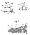
- FIG. 13 is an end view of the outer spacer or sleeve of the quick connector coupling of the present invention showing the rearward end.
- FIG. 14 is a side sectional view of the outer spacer of FIG. 13 .
- FIG. 15 is a sectional side view of a stuffer pin employed with the coupling components of the quick connector coupling of the present invention.
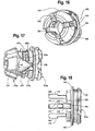
- FIG. 16 is a perspective view, in fully assembled relation, of the tube retainer and insertion verifier embodying the present invention.
- FIG. 17 is a side perspective of a modified form of the tube retainer and insertion verifier components of the quick connector coupling assembly of the present invention.
- FIG. 18 is a side view of the insertion verifier of the assembly of FIG. 17 .
- the fluid coupling assembly 410 of FIGS. 1-15 is a part of a fluid system. It joins a hollow tube 420 to a fluid system component 414 in fluid tight relation.
- the tube 420 defines a male member 412 which includes a radially directed annular upset 422 spaced from the free end of the tube.
- the male member includes an outer cylindrical sealing surface 424 between the tube end and the upset 422.
- the coupling assembly includes a retainer 416, a sealing member 418, an inner spacer 415, and an outer spacer or cylinder 417. These components releasably secure the tube male member 412 to a body component 414 in a fluid tight relation.
- the component body 414 to which the tube is attached is illustrated here as an "ABS unit" of an automotive brake system.
- the component could be a master cylinder, brake caliper, or other high or low pressure system component. It could also be any form of body defining a cavity or bore to receive the tube end and connection components.
- the body component 414 defines a tube, seal, and retainer receiving bore 430.
- the bore 430 shown in FIG. 2 is divided into four portions which extend axially forward from the entrance opening 432. These are a retainer receiving portion 449, a sleeve or cylinder receiving portion 447, a seal receiving portion 450 and a reduced diameter tube receiving portion 451. The latter portion connects to a fluid passage in communication with the interior of the ABS unit or body component of the fluid system.
- the entrance opening 432 is defined by an annular flange or rim 440 with an axial cylindrical surface 436 defining the opening and a forward, radially directed annular abutment, or locking surface 438.
- the sleeve receiving portion 447 includes a cylindrical wall 448 of a diameter larger than the cylindrical wall 444 defining the seal receiving portion of the bore and smaller than the diameter of the cylindrical wall 442 defining the retainer receiving portion of the bore 430.
- a conical surface 459 extends between sleeve receiving portion wall 448 and the wall 444 of the seal receiving portion 450.
- the quick connector coupling assemblage of the present invention is seen in cross section in FIG. 1 .
- the cylindrical sealing surface 424 of the male member 412 of tube 420 is positioned in the tube receiving portion 451 of bore 430.
- the retainer 416 is connected to the annular flange or rim 440 at the entrance opening with locking arms of the retainer extending between the radial abutment surface 438 and the upset 422 formed on the tube 420 to releasably retain the male member portion 412 within the ABS unit or body component 414.
- the retainer 416 is best seen in FIGS. 3-7 .
- the retainer 416 includes a cylindrical ring 456 having an outer cylindrical surface 462 and an inner cylindrical surface 463.
- outer cylindrical surface 462 is somewhat smaller than the diameter of cylindrical surface 436 of rim 440 such that the ring 456 of retainer 416 is loosely piloted therein.
- the inner diameter 463 of ring 465 is larger than the diameter of upset 422 to permit passage through the ring during insertion of tube 420.
- the retainer 416 also includes four axially extending duck bills or locking arms 476 with slots 466 between them.
- the slots 466 are defined by axially extending side faces 467 that terminate at curved end surfaces 468.
- the locking arms 476 of retainer 416 have forward arcuate, generally radial abutment surfaces 478 that abut the tube upset 422 and rearward abutment surfaces 484 that abut locking surface 438 of rim 440 when the retainer 416 is installed into the body component 414.
- the locking arms 476 define top ramped surface 480 interior ramped surface 488 and cylindrical bottom surface 490.
- the locking arms are angled to diverge rearwardly toward rear abutment surfaces 484.
- the upset 422 contacts the interior ramped surfaces 488 and deflects the locking arms 476 radially outward to permit passage of the upset forward beyond the front abutment surfaces 478.
- the upset resides forward of the locking arms 478 and the arms return to their normal position with cylindrical bottom surfaces 490 overlying the cylindrical sealing surface 424 of male member 412 rearward of the upset 422.
- the forward abutment surfaces 478 abut the upset 422.
- the arms 476 also include angled arcuate abutment surfaces 477 radially outward of the forward abutment surfaces 478. These angled abutment surfaces are angled in a rearward direction toward ring 456 at an angle ⁇ , of five to thirty degrees (5° to 30°) to a plane perpendicular to the longitudinal axis of the retainer 416.
- the rearward end of the ring 456 is provided with four radial protrusions 479. Radially inward of each protrusion 479 is a chamfer 483 to guide the insertion verifier.
- each protrusion 479 is a rearwardly directed guide element 481 defined by two angled surfaces 482 formed at an angle of forty-five degrees (45°) to a plane perpendicular to the longitudinal axis of the retainer 416.
- the surfaces are thus ninety degrees (90°) to each other and meet at a central apex.
- the guide surfaces 482 are chamfered to diverge in the forward direction.
- Forward faces 458 on protrusions 479 define a channel 465 with the rear abutment surfaces 484.
- the retainer axial forward movement is limited by the forward faces 458.
- Channel 465 is sized to receive the rim 440 of the body component 414.
- the cylindrical surface 436 of the body component overlies the outer cylindrical surface 462.
- the rim or flange 440 of the body When assembled to the body, the rim or flange 440 of the body resides radially outward of cylindrical surface 462 of ring 456.
- the rear abutment surfaces 484 of locking arms 476 abut the radial annular abutment surface 438 of the body 414 and deliver axial loads from fluid pressure to the radial surface 438 of the body component 414.
- a seal pack including a seal member, in the form of an O-ring seal 418 surrounds the cylindrical surface 424 of the tube 420 and seals to the body component 414 in the seal receiving portion 450 of bore 430.
- Inner spacer 415 is positioned rearward of the O-ring 418. It is made of polytetrofluroethelene (PTFE) and is utilized to reduce effects of vibration and pulsation of pressure on the O-ring seal 418.
- PTFE polytetrofluroethelene
- the outer spacer 417 of the present invention is positioned between the forward abutment surfaces 478 of the locking arms 476 and the inner spacer 415. Best seen in FIGS. 13 and 14 , it is hollow and includes a forward small cylinder portion 485 and a rearward large cylinder portion 486.
- the large cylinder portion 486 includes a rearward conical annular surface 487 angled to diverge radially and rearward toward the locking arms 478 of retainer 416.
- the angle ⁇ of the surface 487 is five to thirty degrees (5° to 30°) to a plane perpendicular to the longitudinal axis of the cylindrical portions 485 and 486 and is complimentary with the angled surfaces 477 of locking arms 476.
- the rearward large cylinder portion 486 defines a tube upset pocket 489. As seen in FIG. 1 , when the coupling is assembled, the upset 422 of the tube 420 resides in the tube upset pocket 489. That is, the inner diameter of the large cylinder portion 486 is larger than the outer diameter of the upset 422.
- the small cylinder portion 485 resides in the seal receiving portion 450 of the bore 430 and the large cylinder portion 486 resides in the sleeve or cylinder receiving portion 447 of bore 430.
- the outer spacer 417 slides into the cavity or bore 430 of the ABS unit 414 with the small cylinder portion received in the seal receiving portion 450 and the large cylinder portion received in the sleeve receiving portion 447.
- annular radial forward end 491 of the small cylinder portion 485 and radial annular wall 446 between the seal receiving portion 450 and tube receiving portion 451 of the bore 430 define the seal pocket or gland area where the O-ring 418 and inner spacer 415 reside.
- the axial forward position of the sleeve or outer spacer 417 is set by contact of annular surface 493 between the small cylinder portion 485 and the large cylinder portion 486 with the conical surface 459 in the bore 430 between the sleeve receiving portion 447 and the seal receiving portion 450 of the bore. This relationship keeps the axial length of the O-ring gland from reducing and overstressing the O-ring.
- the outer spacer 417 of the invention is molded out of plastic or machined from metal. It transfers the fluid pressure load on the O-ring 418 to the angled abutment surfaces 477 on locking arms 476 through contact with complementary angled surface 487 on large cylindrical portion 486.
- the large cylinder portion 486 of the outer spacer eliminates outer spacer contact with the male tube upset 422 which moves the O-ring fluid pressure force from the front abutment surfaces 478 of locking arms 476 to angled abutment surfaces 477 radially outward of the front abutment surfaces 478. Moving the force outward and adding the angled abutment surfaces 477 to the retainer 416 reduces axial compressive stresses on the retainer locking arms 476 to improve impulse fatigue capability.
- the angled abutment surface 477 of the retainer locking arms 476 and angled surface 487 of large outer spacer cylinder portion 486 create an inward tightening force on retainer locking arms 476 to force cylindrical bottom surfaces 490 onto the outer cylindrical surface 424 of the tube rearward of the tube upset 422.
- This clamping force prevents tube-to-retainer disengagement during pressure impulses or side loading or any other force acting on the tube 420. Since the axial force of the O-ring fluid pressure is contacting a larger surface on the locking arms, the compressive stress will be smaller, thus increasing impulse fatigue capability.
- the angled mating surfaces 477 and 487 also transmit a slightly reduced compressive axial force to the retainer locking arms 476 which increases impulse fatigue capability of the retainer locking arms 476.
- the outer spacer rearward angled surface 487 abuts the angled abutment surfaces 477 of the retainer locking arms 476 instead of the tube upset 422. This relationship keeps the outer spacer 417 in correct axial position to keep the seal pack of inner spacer 415 and O-ring 418 in position even after many cycles of temperature and vibration.
- This arrangement also eliminates field issues, in particular, during service procedures. Disengagement of tube will not permit seal pack to fall out since the large cylinder portion 486 on the outer spacer 417 will abut the forward abutment surfaces 478 of the retainer locking arms 476 even in the release position where the locking arms are urged radially outward by a release tool to permit the upset 422 to be withdrawn. This relationship ensures that the sleeve 417 remains in place in bore 430 blocking inadvertent removal of inner spacer 415 and O-ring 418.
- the O-ring 418 is located such that the tube free end contacts the O-ring 418 simultaneously with the tube upset 422 contacting the ramped inner surfaces 488 of retainer locking arms 476. This axial component positioning gives the operator a consistent increasing resisting force during insertion. This resistance force drops off quickly after the mating tube upset 422 is inserted beyond the locking arms 476.
- the retainer locking arms 476 each have an angled abutment face 477 on the forward abutment surface of the duck bill that abuts the outer spacer conical angled surface 487.
- the retainer angled abutment faces 477 were created by adding material to the radial outer portion of the locking arms 476.
- the top ramped surface 480 of locking arms 476 is radially outward of the outer diameter of the tube upset by the radial extent of the angled abutment surfaces 477 of the locking members 476.
- the junction between the radial locking surfaces 478 that abut the radial annular surface 423 of the upset 422 of tube 420 and the angled abutment surfaces 477 that abut the conical surface 489 of sleeve 417 is slightly radially outward of the outer perimeter or outer diameter of the upset 422. This added material to the locking arms creates more abutment surface area to absorb compressive forces created by fluid pressure on O-ring 418 and fluid pressure acting on the end of tube 420.
- the total area of tube upset abutment surfaces 477 and 478 is 15.96mm sq. (4 locking arms X 3.99mm sq.) to handle axial O-ring and tube forces.
- the surface area tube upset abutment surfaces 478 is 10.80mm sq. (4 locking arms X 2.70mm sq.) to handle the tube force.
- the surface area of angled abutment surfaces 477 is 35.76mm sq. to handle O-ring force.
- the retainer 416 of this embodiment has 26.76mm sq. of duck bill abutment surface area that mates with radial abutment surface 438 of the body component. This increases total area at both duck bill contact points for greater performance at high fluid pressures.
- mm sq. means square millimeters of area.
- the quick connector coupling of the present invention also includes an insertion verifier 500 shown in detail in FIGS. 8-12 . It functions somewhat similarly to the secondary latch disclosed in United States patent No. 6,173,994 in that it includes legs that slide into the slots between the locking arms of the retainer. The legs are sized such that the insertion verifier can only be fully inserted if the tube upset is fully inserted and latched, forward of the forward abutment surfaces 478 of the retainer locking arms 476.
- the insertion verifier 500 includes ring 502 having radially inner annular axial wall 520 and a radially outer annular axial wall 522 connected by a rearward radial axial wall.
- the radially inner wall 520 has an inner surface 521 having a diameter slightly larger than the outer cylindrical surface 424 of male member 412 to permit it to slide axially on the tube 420.
- An entrance chamfer 434 aids in inserting free end of tube 420 into bore 521.
- the radially outer annular wall 522 defines with wall 520 a hollow annular space 524 closed by rearward radial annular wall.
- the rearward most terminus of the annular space 524 is defined by angled wall surfaces 526 that are complementary to the angled surfaces 482 of guide elements 481. That is, the wall surfaces 526 are at an angle of ninety degrees (90°) to each other and at an angle of forty-five degrees (45°) to a plane perpendicular to the longitudinal axis of the insertion verifier.
- the angled wall surfaces 526 define four pockets to receive the four guide elements 481.
- the rearward end of retainer ring 456 resides in the annular space 524 when the guide members 481 are disposed in the pockets formed by walls 526.
- Outer annular wall 522 includes four notches 528 to receive the radial protrusions 479 that are extant at the rearward end of the retainer ring 456.
- radial lips 530 extend from rearward end of outer ring 522. These lips are useful in manually retracting the insertion verifier from its inserted position. Such retraction is necessary in order to insert a removal tool into the entrance opening 430 to spread the locking members 476 and permit withdrawal of upset 422 from its latched position in the upset pocket 489.
- Insertion verifier 500 resides on tube 420 rearward of upset 422. It is therefore, a component that must be assembled and shipped with the tube. The tube upset 422 prevents it from being accidentally removed.
- the tube 420 may be connected to the connector coupling body 414 and the retainer 416 using the connection verifier 500.
- the insertion verifier is employed during the insertion process to axially insert the tube male member 420 into the body component 414 and secure the upset 422 forward of the forward abutment surfaces 478 of locking arms 476.
- the insertion verifier 500 includes four axially extending legs that extend forward of the wall 520 of ring 502.
- the verifier includes two legs 504 spaced one hundred eighty degrees (180°) apart and two legs 505 spaced one hundred eighty degrees (180°) apart. These pairs of legs are disposed equally spaced about ring 502.
- the radially inner-arcuate surfaces 507 of the legs are formed on about the same diameter as the inner diameter of inner surface 521 of inner wall 520 of ring 502 and thus slide freely on cylindrical surface 424 of tube male member 412.
- the legs 504 and 505 include radially directed axially extending side walls 513 and have a lateral or circumferential width sized to fit into the slots 466 between the side faces 467 locking arms 476 of the retainer 416.
- Such positioning is possible only if the male member 412 defined by tube 420 is fully inserted into the coupling body cavity or bore 430, with the tube upset 422 disposed forward of the forward abutment surfaces 478 of the locking arms 476 in the upset pocket 489 defined by the large diameter portion 486 of the sleeve or outer spacer 417. When so positioned, the legs can be fully inserted axially between the locking arms 476 because axial forward movement is limited by the position of the upset 422.
- the legs 504 and 505 When fully inserted, the legs 504 and 505 fill the slots 466 and prevent collapse of the locking arms 476 of retainer 416 toward the outer cylindrical surface 424 of tube 420. This relationship provides added strength and durability to the connection. This interrelationship is best seen in FIG. 16 . There the legs 504 and 505 of the insertion verifier 500 are fully inserted into the slots between the retainer locking arms 476. The volume occupied by the legs 504 and 505 within the slots 466 provides stability to prevent accidental disconnection of the locking arms even in vibratory conditions.
- Two of the legs 504 include radially outwardly directed pads 510.
- Pads 510 include a forward rotational guide 511.
- Each guide 511 is defined by two guide surfaces 512 that forwardly converge meet at an apex mid way between the side walls 513 of the legs 504 and extend rearwardly from the point at an angle of forty five degrees (45°) to the axial side walls 513 of the legs 504, i.e. ninety degrees (90°) to each other.
- the guide surfaces 512 have a forward pitch or angle ⁇ to be complementary to the chamfers on the guide surfaces 482 on the guide elements 481.
- each pad 510 includes a latching surface 514.
- the latching surfaces 514 catch the end surfaces 468 defining the rearward terminus of the slots 466 to releasably secure the verifier 500 to the retainer 416.
- These latching surfaces are sloped rearward. They are arranged to catch on surfaces 468 to hold the verifier 500 in the assembled coupling. However, the slope, of thirty degrees (30°) to a plane perpendicular to the longitudinal axis of the verifier 500 permits these surfaces to be unlatched on physical effort to pull the verifier axially rearward.
- the other two legs 505 of the verifier 500 each include a radially extended block portion 516.
- the blocks 516 on legs 505 are located adjacent the distal end of the legs and extend rearwardly and terminate at about the same axial position as the point formed by guide surfaces 512 on pads 510 of legs 504.
- This block portion adds bulk to the legs and fills the volume of the slot 466 into which leg 505 is inserted to further enhance the latching strength of the assemblage.
- the added mass of legs 505 provided by blocks 516 aids in insertion of the tube male member 412 into bore 430 when the insertion verifier 500 is employed for that function by applying axial force to the verifier ring 502.
- the radial thickness of the legs 505 at blocks 516 is about the same as the radial thickness of legs 504 rearward and forward of the pads 510.
- the radial thickness of legs 504 exceeds the radial thickness of the legs 505 at blocks 516.
- the pads 510 on legs 504 are located about midway between the distal end of the leg and its connection to annular ring 502.
- the radial thickness of legs 505 between blocks 516 and the connection of legs 505 to inner annular wall 520 is about half the radial thickness of the legs 504, or the thickness of the legs 505 at blocks 516.
- the outer surface of the legs 505 between the blocks 516 and the connection to annular wall 520 creates a void or open space to permit deflection of the annular ring 456 of retainer 416 radially inwardly during insertion and removal of the legs 504 and 505 of insertion verifier 500.
- the insertion verifier 500 is assembled by sliding insertion verifier axially on tube 420 so the guide surfaces 512 of pads 510 contact the retainer guide elements 481 creating a rotation of the retainer 416 that aligns the legs 504 and 505 with the slots 466.
- the insertion verifier pads 510 will expand, or deform the annular ring 456 of the retainer 414 outward until the rear latching surfaces 514 move past the forward surfaces 468 between the retainer locking arms 476 and lock in place.
- the retainer ring 456 will bow inward ninety degrees (90°) from the contacted points during insertion verifier assembly.
- the relative thickness of the legs 505 between the blocks 516 and connection of the legs to inner annular wall 520 permits such radially inward distortion of retainer ring 456.
- verifier and retainer The assembled relationship of verifier and retainer is best illustrated in FIG. 17 .
- the legs 504 and 505 of verifier 500 prevent the duck bill locking arms 476 from flexing radially inward, adding to the overall resistance to unintentional unlatching of the retainer 416 from rim 440 of the bore 430.
- the length and width of the four insertion verifier legs are selected so that the legs fit in slots 466 between side faces 467 of retainer locking arms 476 so the legs 504 and 505 will contact the tube upset and propel the tube upset past the retainer locking arms before the latching surfaces 514 latch onto surfaces 468 in slots 466 of retainer 416.
- Full insertion of the tube end is accomplished by axially moving the verifier 500 forward.
- the legs 504 and 505 contact upset 422 and urge it toward, and beyond, the retainer locking arms with the forward locking surfaces 478 disposed in abutting relation to the upset 422.
- the upset resides in the upset pocket 489 formed by the large diameter cylinder portion 486 of outer spacer 417.
- the legs 504 and 505 of the verifier 500 reside in slots 466 with latching surfaces 514 latched to rearward surfaces 468 of retainer 416.
- verifier radial lips 530 on the outside diameter that can be gripped manually to pull insertion verifier rearward axially along tube 420 and out of the retainer 416.
- the ring 456 of retainer 416 will deform at the two contacts with the pads 510 radially outward at two places one hundred eighty degrees (180°) apart. Such deformation permits the latching surfaces 514 to disengage from the surfaces 468 and withdrawal of the retainer legs 504 and 505 from slots 466.
- a stuffer pin 601 illustrated in FIG. 15 is used to assemble quick connector components into a system component receiving bore such as bore 430.
- Stuffer pins are made of plastic while the receiving component is usually made out of metal for high pressure brake or power steering applications and usually plastic for low pressure applications such as liquid fuel or fuel vapor.
- the retainer 416, outer sleeve, 417, seal member 418, and inner spacer 415 are preassembled onto stuffer pin 601.
- a removable protective cap is provided which protects these components prior to installation. To assemble the components into a body component 414 the protective cap is removed and discarded.
- the stuffer pin is used to insert these components into the body component 414.
- the body component is thus pre-loaded with the coupling components to receive and secure the male member 412 of the tube 420.
- the stuffer pin 601 contains appropriately formed grooves and cylinders to hold the components in place during shipping.
- the stuffer pin grooves and cylinders also allow insertion and retraction of stuffer pin into a receiving bore of a system body component so that the retainer and sealing components are assembled in correct positions without incurring any damage or misalignment.
- the retainer 416 and outer spacer 417 of the present invention hold the O-ring 418 and inner spacer 415 inside the receiving bore 430 during stuffer pin retraction in the same manner as it retains those components in place during removal of a previously coupled tube 420.
- the contact of angled surface 487 of outer spacer 417 with angled abutment surfaces 478 prevents accidental dislodgement or removal because retainer 416 is secured to rim 440 of the body component 414.
- Outer spacers are part of the "seal pack" used in all quick connectors.
- the "seal pack” consists of an O-ring and spacers that encompass the outside diameter of mating tube. The compression of the O-rings to the tube creates the seal while the inner spacer creates the shoulder of the gland area where the O-ring resides.
- the outer spacer is the last component of the "seal pack" to be assembled and it therefore must keep the O-ring from blowing out when fluid pressure is applied.
- Past designs utilize a light press fit or a shoulder snap fit to resist the fluid pressure. Fuel applications with the interference snap fit hold up to 150 psi while transmission oil cooler applications utilize a press fit which holds up to 300 psi.
- the connection of the retainer 416 to the rim 440 receives this load and performs the function of holding the outer spacer 417 in its proper position even at the high pressures experienced in brake system applications.
- FIGS. 17 and 18 a retainer 416a and an insertion verifier 500a are illustrated with modification as described below.
- FIG. 17 a somewhat modified form of guide element 481 a is illustrated.
- the angled surfaces 482a of each guide element 481a are at a greater angle, to each other, here 53°. This relationship results in the guide elements 481a being longer in the axial direction than the guide elements 481 of FIGS. 1-16 .
- the guide surfaces 482a therefore impart a greater relative rotational component to the insertion verifier 500a on insertion into the retainer.
- an insertion verifier 500a is shown which is modified somewhat from the insertion verifier 500 of FIGS. 1-16 . It includes a forwardly directed guide element 550 aligned with each of the legs 504 and 505. It is formed by two angled surfaces 552 at an angle of 12 1 ⁇ 2° to a plane perpendicular to the axial extent of a verifier 500a and meet at an apex. These surfaces are positioned in alignment with the legs and are intended to impart a relative rotational force component to the insertion verifier in the event the legs 504 and 505 are not aligned with the slots 466 of the retainer 416 and the guide elements 481 of the guide elements 481 somehow override the guide surfaces 512 on pads 510.
- the legs 504 and 505 will align with the locking arms 476.
- the legs will contact the interior ramped surfaces 488 and urge the free ends of the locking arms radially outwardly, away from the tube surface 424.
- the axial length of guide elements 440 is such that the apex of each guide element contacts the rearward radial annular wall before the legs 504 and 505 lift the locking arms 476 sufficiently to permit passage of the upset 422 rearwardly. This relationship prevents the misaligned insertion verifier from inadvertently releasing the tube from the assembly.
- Insertion verifier 500a also includes a radial outwardly directed rim 560 immediately rearward of notches 528 in outer annular wall 522. This rim is intended to deter attempts to remove the insertion verifier with a tool not intended for that purpose. When the insertion verifier 500a is inserted into a coupling assembly the rim 560 is spaced from the surface at entrance opening of bore 430 in body component 414. This relationship deters use of tools such as wrenches to remove the insertion verifier.
Landscapes
- Engineering & Computer Science (AREA)
- General Engineering & Computer Science (AREA)
- Mechanical Engineering (AREA)
- Quick-Acting Or Multi-Walled Pipe Joints (AREA)
- Discharge Heating (AREA)
- Flanged Joints, Insulating Joints, And Other Joints (AREA)
Abstract
Description
- Background of the Invention
- This application relates to quick connector coupling assemblies for fluid systems, and more particularly to a quick connector for high pressure applications that releasably connects a male member formed at the end of a hollow tube to a hollow connector body.
- In the automotive and other fields, a quick connector coupling assembly is often utilized to provide a fluid connection between two components or conduits which generally include a male member, or tube, received and retained in a female connector body. Use of a quick connector is advantageous in that a sealed and secure fluid line may be established with minimum amount of time and expense.
- A retainer is often used to secure the male member within the connector body. One such type of retainer includes a plurality of locking members which extend between a radially enlarged upset formed on the male member and an annular face defined in the connector body. The abutment of the retainer with the upset of the male member at one end and the annular face of the connector body at the other end prevents the withdrawal of the male member from the connector body. This type of retainer is prevalent in the art and has proven effective in many fluid line applications.
- A seal member, usually in the form of an O-ring seal, is used with a quick connector coupling to create a fluid tight seal between the male member and the connector body. In such a configuration, the O-ring is located axially inwardly of the retainer and separated by an annular spacer slidably mounted on the male member. It is often held against axial load imparted by fluid pressure by a spacer that is press fit, or in a snap fit relation to the bore in which it is received. Since the retainer is somewhat flexible, and the O-ring is slidably linked with the retainer, the O-ring is able to slide slightly relative to the male member. Also, such quick connector assemblies are often used in applications where the components are subject to high temperature or pressure, as well as vibration and cyclic application of pressure. These conditions increase the difficulty of maintaining a fluid tight joint. In high pressure applications such as automotive brake systems, it is necessary to ensure that the axial force imparted to the components be reliably accommodated.
- Other known arrangements incorporate a sleeve arrangement to transfer axial load imparted to the seal ring by fluid pressure to the retainer through the upset formed on the male member or tube. In one embodiment, an additional spacer made of Teflon polymer located between the seal member and the sleeve is also used to minimize the effects of vibration and cyclic load.
- This invention, which is defined in claim 1, is directed to an improved form of insertion verifier/latch that serves the functions of providing verification of the complete insertion of the male member into the body of the connector assembly, and also provides a latching function to stabilize the locking arms of the tube retainer to suppress inward movement and increase overall burst pressure performance. The insertion verifier/latch also serves to close the entrance into the connector body to minimize entry of contaminants. Additional features of the invention are disclosed in the dependent claims.
-
FIG. 1 is a side sectional of the quick connector coupling assembly of the present invention with the tube releasably connected to the body component and the connection verifier positioned on the tube rearward of the tube upset. -
FIG. 2 is a sectional side view of the coupling receiving bore in the system component of the quick connector coupling assembly ofFIG. 1 . -
FIG. 3 is a side view of the retainer of the present invention -
FIG. 4 is a plan view of the forward end of the retainer ofFIG. 3 . -
FIG. 5 is a side sectional view of the retainer ofFIG. 3 taken along the line 5-5 ofFIG. 4 . -
FIG. 6 is a plan view of the rearward end of the retainer ofFIG. 3 rotated forty-five degrees (45°) relative toFIG. 4 . -
FIG. 7 is a side view of the retainer ofFIG. 6 . -
FIG. 8 is a plan view of the rearward end of the insertion verifier of the present invention. -
FIG. 9 is a side view of the insertion verifier ofFIG. 8 . -
FIG. 10 is a side view of the insertion verifier ofFIG. 8 rotated forty-five degrees (45°) relative toFIG. 9 . -
FIG. 11 is a plan view of the forward end of the insertion verifier ofFIG. 8 . -
FIG. 12 is a side sectional view of the insertion verifier ofFIG. 8 taken along the line 12-12 ofFIG. 11 . -
FIG. 13 is an end view of the outer spacer or sleeve of the quick connector coupling of the present invention showing the rearward end. -
FIG. 14 is a side sectional view of the outer spacer ofFIG. 13 . -
FIG. 15 is a sectional side view of a stuffer pin employed with the coupling components of the quick connector coupling of the present invention. -
FIG. 16 is a perspective view, in fully assembled relation, of the tube retainer and insertion verifier embodying the present invention. -
FIG. 17 is a side perspective of a modified form of the tube retainer and insertion verifier components of the quick connector coupling assembly of the present invention. -
FIG. 18 is a side view of the insertion verifier of the assembly ofFIG. 17 . - The
fluid coupling assembly 410 ofFIGS. 1-15 is a part of a fluid system. It joins ahollow tube 420 to afluid system component 414 in fluid tight relation. Thetube 420 defines amale member 412 which includes a radially directedannular upset 422 spaced from the free end of the tube. The male member includes an outercylindrical sealing surface 424 between the tube end and theupset 422. - The coupling assembly includes a
retainer 416, a sealingmember 418, aninner spacer 415, and an outer spacer orcylinder 417. These components releasably secure thetube male member 412 to abody component 414 in a fluid tight relation. - The
component body 414 to which the tube is attached is illustrated here as an "ABS unit" of an automotive brake system. However, the component could be a master cylinder, brake caliper, or other high or low pressure system component. It could also be any form of body defining a cavity or bore to receive the tube end and connection components. - As seen in
FIG. 2 , thebody component 414 defines a tube, seal, andretainer receiving bore 430. Thebore 430 shown inFIG. 2 is divided into four portions which extend axially forward from theentrance opening 432. These are aretainer receiving portion 449, a sleeve orcylinder receiving portion 447, aseal receiving portion 450 and a reduced diametertube receiving portion 451. The latter portion connects to a fluid passage in communication with the interior of the ABS unit or body component of the fluid system. - The
entrance opening 432 is defined by an annular flange orrim 440 with an axialcylindrical surface 436 defining the opening and a forward, radially directed annular abutment, orlocking surface 438. - The
sleeve receiving portion 447 includes acylindrical wall 448 of a diameter larger than thecylindrical wall 444 defining the seal receiving portion of the bore and smaller than the diameter of thecylindrical wall 442 defining the retainer receiving portion of thebore 430. Aconical surface 459 extends between sleeve receivingportion wall 448 and thewall 444 of theseal receiving portion 450. - The quick connector coupling assemblage of the present invention is seen in cross section in
FIG. 1 . Thecylindrical sealing surface 424 of themale member 412 oftube 420 is positioned in thetube receiving portion 451 ofbore 430. Theretainer 416 is connected to the annular flange orrim 440 at the entrance opening with locking arms of the retainer extending between theradial abutment surface 438 and theupset 422 formed on thetube 420 to releasably retain themale member portion 412 within the ABS unit orbody component 414. - The
retainer 416 is best seen inFIGS. 3-7 . Theretainer 416 includes acylindrical ring 456 having an outercylindrical surface 462 and an innercylindrical surface 463. - The diameter of outer
cylindrical surface 462 is somewhat smaller than the diameter ofcylindrical surface 436 ofrim 440 such that thering 456 ofretainer 416 is loosely piloted therein. Theinner diameter 463 ofring 465 is larger than the diameter ofupset 422 to permit passage through the ring during insertion oftube 420. - The
retainer 416 also includes four axially extending duck bills or lockingarms 476 withslots 466 between them. Theslots 466 are defined by axially extending side faces 467 that terminate at curved end surfaces 468. - The locking
arms 476 ofretainer 416 have forward arcuate, generally radial abutment surfaces 478 that abut the tube upset 422 and rearward abutment surfaces 484 thatabut locking surface 438 ofrim 440 when theretainer 416 is installed into thebody component 414. - The locking
arms 476 define top rampedsurface 480 interior rampedsurface 488 and cylindricalbottom surface 490. The locking arms are angled to diverge rearwardly toward rear abutment surfaces 484. On insertion of themale member 412 of thetube 420 into the entrance opening 430 the upset 422 contacts the interior rampedsurfaces 488 and deflects the lockingarms 476 radially outward to permit passage of the upset forward beyond the front abutment surfaces 478. When the tube is fully inserted, the upset resides forward of the lockingarms 478 and the arms return to their normal position with cylindrical bottom surfaces 490 overlying thecylindrical sealing surface 424 ofmale member 412 rearward of the upset 422. The forward abutment surfaces 478 abut the upset 422. - The
arms 476 also include angled arcuate abutment surfaces 477 radially outward of the forward abutment surfaces 478. These angled abutment surfaces are angled in a rearward direction towardring 456 at an angle α, of five to thirty degrees (5° to 30°) to a plane perpendicular to the longitudinal axis of theretainer 416. - The rearward end of the
ring 456 is provided with fourradial protrusions 479. Radially inward of eachprotrusion 479 is achamfer 483 to guide the insertion verifier. - Intermediate each
protrusion 479 is a rearwardly directedguide element 481 defined by twoangled surfaces 482 formed at an angle of forty-five degrees (45°) to a plane perpendicular to the longitudinal axis of theretainer 416. The surfaces are thus ninety degrees (90°) to each other and meet at a central apex. The guide surfaces 482 are chamfered to diverge in the forward direction. - Forward faces 458 on
protrusions 479 define achannel 465 with the rear abutment surfaces 484. The retainer axial forward movement is limited by the forward faces 458.Channel 465 is sized to receive therim 440 of thebody component 414. Thecylindrical surface 436 of the body component overlies the outercylindrical surface 462. - When assembled to the body, the rim or
flange 440 of the body resides radially outward ofcylindrical surface 462 ofring 456. The rear abutment surfaces 484 of lockingarms 476 abut the radialannular abutment surface 438 of thebody 414 and deliver axial loads from fluid pressure to theradial surface 438 of thebody component 414. - A seal pack, including a seal member, in the form of an O-
ring seal 418 surrounds thecylindrical surface 424 of thetube 420 and seals to thebody component 414 in theseal receiving portion 450 ofbore 430.Inner spacer 415 is positioned rearward of the O-ring 418. It is made of polytetrofluroethelene (PTFE) and is utilized to reduce effects of vibration and pulsation of pressure on the O-ring seal 418. - The
outer spacer 417 of the present invention is positioned between the forward abutment surfaces 478 of the lockingarms 476 and theinner spacer 415. Best seen inFIGS. 13 and 14 , it is hollow and includes a forwardsmall cylinder portion 485 and a rearwardlarge cylinder portion 486. Thelarge cylinder portion 486 includes a rearward conicalannular surface 487 angled to diverge radially and rearward toward the lockingarms 478 ofretainer 416. The angle β of thesurface 487 is five to thirty degrees (5° to 30°) to a plane perpendicular to the longitudinal axis of thecylindrical portions angled surfaces 477 of lockingarms 476. - The rearward
large cylinder portion 486 defines a tubeupset pocket 489. As seen inFIG. 1 , when the coupling is assembled, the upset 422 of thetube 420 resides in the tubeupset pocket 489. That is, the inner diameter of thelarge cylinder portion 486 is larger than the outer diameter of the upset 422. - In the assemblage shown in
FIG. 1 , thesmall cylinder portion 485 resides in theseal receiving portion 450 of thebore 430 and thelarge cylinder portion 486 resides in the sleeve orcylinder receiving portion 447 ofbore 430. Theouter spacer 417 slides into the cavity or bore 430 of theABS unit 414 with the small cylinder portion received in theseal receiving portion 450 and the large cylinder portion received in thesleeve receiving portion 447. - The annular radial
forward end 491 of thesmall cylinder portion 485 and radialannular wall 446 between theseal receiving portion 450 andtube receiving portion 451 of thebore 430 define the seal pocket or gland area where the O-ring 418 andinner spacer 415 reside. - The axial forward position of the sleeve or
outer spacer 417 is set by contact ofannular surface 493 between thesmall cylinder portion 485 and thelarge cylinder portion 486 with theconical surface 459 in thebore 430 between thesleeve receiving portion 447 and theseal receiving portion 450 of the bore. This relationship keeps the axial length of the O-ring gland from reducing and overstressing the O-ring. - The
outer spacer 417 of the invention is molded out of plastic or machined from metal. It transfers the fluid pressure load on the O-ring 418 to the angled abutment surfaces 477 on lockingarms 476 through contact with complementaryangled surface 487 on largecylindrical portion 486. - The
large cylinder portion 486 of the outer spacer eliminates outer spacer contact with the male tube upset 422 which moves the O-ring fluid pressure force from the front abutment surfaces 478 of lockingarms 476 to angled abutment surfaces 477 radially outward of the front abutment surfaces 478. Moving the force outward and adding the angled abutment surfaces 477 to theretainer 416 reduces axial compressive stresses on theretainer locking arms 476 to improve impulse fatigue capability. - The
angled abutment surface 477 of theretainer locking arms 476 andangled surface 487 of large outerspacer cylinder portion 486 create an inward tightening force onretainer locking arms 476 to force cylindrical bottom surfaces 490 onto the outercylindrical surface 424 of the tube rearward of the tube upset 422. This clamping force prevents tube-to-retainer disengagement during pressure impulses or side loading or any other force acting on thetube 420. Since the axial force of the O-ring fluid pressure is contacting a larger surface on the locking arms, the compressive stress will be smaller, thus increasing impulse fatigue capability. The angled mating surfaces 477 and 487 also transmit a slightly reduced compressive axial force to theretainer locking arms 476 which increases impulse fatigue capability of theretainer locking arms 476. - With the present invention, the outer spacer rearward angled
surface 487 abuts the angled abutment surfaces 477 of theretainer locking arms 476 instead of the tube upset 422. This relationship keeps theouter spacer 417 in correct axial position to keep the seal pack ofinner spacer 415 and O-ring 418 in position even after many cycles of temperature and vibration. - This arrangement also eliminates field issues, in particular, during service procedures. Disengagement of tube will not permit seal pack to fall out since the
large cylinder portion 486 on theouter spacer 417 will abut the forward abutment surfaces 478 of theretainer locking arms 476 even in the release position where the locking arms are urged radially outward by a release tool to permit the upset 422 to be withdrawn. This relationship ensures that thesleeve 417 remains in place inbore 430 blocking inadvertent removal ofinner spacer 415 and O-ring 418. - The O-
ring 418 is located such that the tube free end contacts the O-ring 418 simultaneously with the tube upset 422 contacting the rampedinner surfaces 488 ofretainer locking arms 476. This axial component positioning gives the operator a consistent increasing resisting force during insertion. This resistance force drops off quickly after the mating tube upset 422 is inserted beyond the lockingarms 476. - As mentioned above, the
retainer locking arms 476 each have an angledabutment face 477 on the forward abutment surface of the duck bill that abuts the outer spacer conicalangled surface 487. - The retainer angled abutment faces 477 were created by adding material to the radial outer portion of the locking
arms 476. As compared to a retainer with locking arms such asarms 476 that include forward abutment surfaces such assurfaces 478 that abut only the rearward facing radialannular surface 423 ofupset 422 oftube 420. That is, the top rampedsurface 480 of lockingarms 476 is radially outward of the outer diameter of the tube upset by the radial extent of the angled abutment surfaces 477 of the lockingmembers 476. The junction between the radial locking surfaces 478 that abut the radialannular surface 423 of the upset 422 oftube 420 and the angled abutment surfaces 477 that abut theconical surface 489 ofsleeve 417 is slightly radially outward of the outer perimeter or outer diameter of the upset 422. This added material to the locking arms creates more abutment surface area to absorb compressive forces created by fluid pressure on O-ring 418 and fluid pressure acting on the end oftube 420. - For an
exemplary coupling assembly 410 having atube 420 with an outer diameter of 0.375 inches, the total area of tube upset abutment surfaces 477 and 478 is 15.96mm sq. (4 locking arms X 3.99mm sq.) to handle axial O-ring and tube forces. The surface area tube upset abutment surfaces 478 is 10.80mm sq. (4 locking arms X 2.70mm sq.) to handle the tube force. The surface area of angled abutment surfaces 477 is 35.76mm sq. to handle O-ring force. - The
retainer 416 of this embodiment has 26.76mm sq. of duck bill abutment surface area that mates withradial abutment surface 438 of the body component. This increases total area at both duck bill contact points for greater performance at high fluid pressures. - In this latter discussion, the term "mm sq." means square millimeters of area.
- The quick connector coupling of the present invention also includes an
insertion verifier 500 shown in detail inFIGS. 8-12 . It functions somewhat similarly to the secondary latch disclosed in United States patent No.6,173,994 in that it includes legs that slide into the slots between the locking arms of the retainer. The legs are sized such that the insertion verifier can only be fully inserted if the tube upset is fully inserted and latched, forward of the forward abutment surfaces 478 of theretainer locking arms 476. - The
insertion verifier 500 includesring 502 having radially inner annularaxial wall 520 and a radially outer annularaxial wall 522 connected by a rearward radial axial wall. The radiallyinner wall 520 has aninner surface 521 having a diameter slightly larger than the outercylindrical surface 424 ofmale member 412 to permit it to slide axially on thetube 420. Anentrance chamfer 434 aids in inserting free end oftube 420 intobore 521. - The radially outer
annular wall 522 defines with wall 520 a hollowannular space 524 closed by rearward radial annular wall. The rearward most terminus of theannular space 524 is defined by angled wall surfaces 526 that are complementary to theangled surfaces 482 ofguide elements 481. That is, the wall surfaces 526 are at an angle of ninety degrees (90°) to each other and at an angle of forty-five degrees (45°) to a plane perpendicular to the longitudinal axis of the insertion verifier. - The angled wall surfaces 526 define four pockets to receive the four
guide elements 481. The rearward end ofretainer ring 456 resides in theannular space 524 when theguide members 481 are disposed in the pockets formed bywalls 526. Outerannular wall 522 includes fournotches 528 to receive theradial protrusions 479 that are extant at the rearward end of theretainer ring 456. - Four
radial lips 530 extend from rearward end ofouter ring 522. These lips are useful in manually retracting the insertion verifier from its inserted position. Such retraction is necessary in order to insert a removal tool into the entrance opening 430 to spread the lockingmembers 476 and permit withdrawal of upset 422 from its latched position in theupset pocket 489. -
Insertion verifier 500 resides ontube 420 rearward ofupset 422. It is therefore, a component that must be assembled and shipped with the tube. The tube upset 422 prevents it from being accidentally removed. - The
tube 420 may be connected to theconnector coupling body 414 and theretainer 416 using theconnection verifier 500. As explained below, the insertion verifier is employed during the insertion process to axially insert thetube male member 420 into thebody component 414 and secure the upset 422 forward of the forward abutment surfaces 478 of lockingarms 476. - The
insertion verifier 500 includes four axially extending legs that extend forward of thewall 520 ofring 502. The verifier includes twolegs 504 spaced one hundred eighty degrees (180°) apart and twolegs 505 spaced one hundred eighty degrees (180°) apart. These pairs of legs are disposed equally spaced aboutring 502. The radially inner-arcuate surfaces 507 of the legs are formed on about the same diameter as the inner diameter ofinner surface 521 ofinner wall 520 ofring 502 and thus slide freely oncylindrical surface 424 oftube male member 412. - The
legs side walls 513 and have a lateral or circumferential width sized to fit into theslots 466 between the side faces 467 lockingarms 476 of theretainer 416. Such positioning is possible only if themale member 412 defined bytube 420 is fully inserted into the coupling body cavity or bore 430, with the tube upset 422 disposed forward of the forward abutment surfaces 478 of the lockingarms 476 in theupset pocket 489 defined by thelarge diameter portion 486 of the sleeve orouter spacer 417. When so positioned, the legs can be fully inserted axially between the lockingarms 476 because axial forward movement is limited by the position of the upset 422. When fully inserted, thelegs slots 466 and prevent collapse of the lockingarms 476 ofretainer 416 toward the outercylindrical surface 424 oftube 420. This relationship provides added strength and durability to the connection. This interrelationship is best seen inFIG. 16 . There thelegs insertion verifier 500 are fully inserted into the slots between theretainer locking arms 476. The volume occupied by thelegs slots 466 provides stability to prevent accidental disconnection of the locking arms even in vibratory conditions. - It has been found that the
retainer locking arms 478 unfold from the outside, in, during burst testing. It has been found that the burst pressure value will increase with the addition of the insertion verifier with its legs in the slots which will keep the unfolding motion from progressing. The faces 467 of the lockingarms defining slots 466 squeeze together during burst unfolding so the presence of the insertion verifier legs restrict this movement and increase failure pressure. - Two of the
legs 504 include radially outwardly directedpads 510.Pads 510 include a forwardrotational guide 511. Eachguide 511 is defined by twoguide surfaces 512 that forwardly converge meet at an apex mid way between theside walls 513 of thelegs 504 and extend rearwardly from the point at an angle of forty five degrees (45°) to theaxial side walls 513 of thelegs 504, i.e. ninety degrees (90°) to each other. The guide surfaces 512 have a forward pitch or angle β to be complementary to the chamfers on the guide surfaces 482 on theguide elements 481. On axial insertion of the insertion verifier alongtube 420 contact of the guide surfaces 512 withangled surfaces 482 ofguide elements 481 results in rotation of theretainer 416 to alignlegs chamfers 483 to align the legs withslots 466 and permit the legs to pass into theslots 466 between the side surfaces 467 of lockingarms 476. - The rearward end of each
pad 510 includes a latchingsurface 514. On full insertion oflegs 504 between lockingarms 476, the latchingsurfaces 514 catch the end surfaces 468 defining the rearward terminus of theslots 466 to releasably secure theverifier 500 to theretainer 416. These latching surfaces are sloped rearward. They are arranged to catch onsurfaces 468 to hold theverifier 500 in the assembled coupling. However, the slope, of thirty degrees (30°) to a plane perpendicular to the longitudinal axis of theverifier 500 permits these surfaces to be unlatched on physical effort to pull the verifier axially rearward. - The other two
legs 505 of theverifier 500, those not provided withpads 510, each include a radially extendedblock portion 516. Theblocks 516 onlegs 505 are located adjacent the distal end of the legs and extend rearwardly and terminate at about the same axial position as the point formed byguide surfaces 512 onpads 510 oflegs 504. This block portion adds bulk to the legs and fills the volume of theslot 466 into whichleg 505 is inserted to further enhance the latching strength of the assemblage. The added mass oflegs 505 provided byblocks 516 aids in insertion of thetube male member 412 intobore 430 when theinsertion verifier 500 is employed for that function by applying axial force to theverifier ring 502. - It should be noted that the radial thickness of the
legs 505 atblocks 516 is about the same as the radial thickness oflegs 504 rearward and forward of thepads 510. At thepads 510, the radial thickness oflegs 504 exceeds the radial thickness of thelegs 505 atblocks 516. Thepads 510 onlegs 504 are located about midway between the distal end of the leg and its connection toannular ring 502. The radial thickness oflegs 505 betweenblocks 516 and the connection oflegs 505 to innerannular wall 520 is about half the radial thickness of thelegs 504, or the thickness of thelegs 505 atblocks 516. Thus, the outer surface of thelegs 505 between theblocks 516 and the connection toannular wall 520 creates a void or open space to permit deflection of theannular ring 456 ofretainer 416 radially inwardly during insertion and removal of thelegs insertion verifier 500. - The
insertion verifier 500 is assembled by sliding insertion verifier axially ontube 420 so the guide surfaces 512 ofpads 510 contact theretainer guide elements 481 creating a rotation of theretainer 416 that aligns thelegs slots 466. During assembly, theinsertion verifier pads 510 will expand, or deform theannular ring 456 of theretainer 414 outward until the rear latching surfaces 514 move past theforward surfaces 468 between theretainer locking arms 476 and lock in place. At the same time, theretainer ring 456 will bow inward ninety degrees (90°) from the contacted points during insertion verifier assembly. As previously described, the relative thickness of thelegs 505 between theblocks 516 and connection of the legs to innerannular wall 520 permits such radially inward distortion ofretainer ring 456. - The assembled relationship of verifier and retainer is best illustrated in
FIG. 17 . When so positioned thelegs verifier 500 prevent the duckbill locking arms 476 from flexing radially inward, adding to the overall resistance to unintentional unlatching of theretainer 416 fromrim 440 of thebore 430. - The length and width of the four insertion verifier legs are selected so that the legs fit in
slots 466 between side faces 467 ofretainer locking arms 476 so thelegs surfaces 468 inslots 466 ofretainer 416. Full insertion of the tube end is accomplished by axially moving theverifier 500 forward. - The
legs upset pocket 489 formed by the largediameter cylinder portion 486 ofouter spacer 417. Thelegs verifier 500 reside inslots 466 with latchingsurfaces 514 latched torearward surfaces 468 ofretainer 416. With insertion verifier fully locked into the retainer, the primary latching of tube upset to retainer is guaranteed. Once the insertion verifier is fully assembled its close fit to the retainer will keep debris and contaminants from getting inside the connector to improve serviceability. To service, verifierradial lips 530 on the outside diameter that can be gripped manually to pull insertion verifier rearward axially alongtube 420 and out of theretainer 416. Thering 456 ofretainer 416 will deform at the two contacts with thepads 510 radially outward at two places one hundred eighty degrees (180°) apart. Such deformation permits the latching surfaces 514 to disengage from thesurfaces 468 and withdrawal of theretainer legs slots 466. - A
stuffer pin 601 illustrated inFIG. 15 is used to assemble quick connector components into a system component receiving bore such asbore 430. Stuffer pins are made of plastic while the receiving component is usually made out of metal for high pressure brake or power steering applications and usually plastic for low pressure applications such as liquid fuel or fuel vapor. Theretainer 416, outer sleeve, 417,seal member 418, andinner spacer 415 are preassembled ontostuffer pin 601. A removable protective cap is provided which protects these components prior to installation. To assemble the components into abody component 414 the protective cap is removed and discarded. - The stuffer pin is used to insert these components into the
body component 414. The body component is thus pre-loaded with the coupling components to receive and secure themale member 412 of thetube 420. Thestuffer pin 601 contains appropriately formed grooves and cylinders to hold the components in place during shipping. The stuffer pin grooves and cylinders also allow insertion and retraction of stuffer pin into a receiving bore of a system body component so that the retainer and sealing components are assembled in correct positions without incurring any damage or misalignment. - The
retainer 416 andouter spacer 417 of the present invention hold the O-ring 418 andinner spacer 415 inside the receiving bore 430 during stuffer pin retraction in the same manner as it retains those components in place during removal of a previously coupledtube 420. The contact ofangled surface 487 ofouter spacer 417 with angled abutment surfaces 478 prevents accidental dislodgement or removal becauseretainer 416 is secured torim 440 of thebody component 414. - Outer spacers are part of the "seal pack" used in all quick connectors. The "seal pack" consists of an O-ring and spacers that encompass the outside diameter of mating tube. The compression of the O-rings to the tube creates the seal while the inner spacer creates the shoulder of the gland area where the O-ring resides. The outer spacer is the last component of the "seal pack" to be assembled and it therefore must keep the O-ring from blowing out when fluid pressure is applied. Past designs utilize a light press fit or a shoulder snap fit to resist the fluid pressure. Fuel applications with the interference snap fit hold up to 150 psi while transmission oil cooler applications utilize a press fit which holds up to 300 psi. In the arrangement of the present invention the connection of the
retainer 416 to therim 440 receives this load and performs the function of holding theouter spacer 417 in its proper position even at the high pressures experienced in brake system applications. - Turning to
FIGS. 17 and 18 , aretainer 416a and aninsertion verifier 500a are illustrated with modification as described below. - In
FIG. 17 , a somewhat modified form ofguide element 481 a is illustrated. Theangled surfaces 482a of eachguide element 481a are at a greater angle, to each other, here 53°. This relationship results in theguide elements 481a being longer in the axial direction than theguide elements 481 ofFIGS. 1-16 . Theguide surfaces 482a therefore impart a greater relative rotational component to theinsertion verifier 500a on insertion into the retainer. - Best seen in
FIG. 18 , aninsertion verifier 500a is shown which is modified somewhat from theinsertion verifier 500 ofFIGS. 1-16 . It includes a forwardly directedguide element 550 aligned with each of thelegs angled surfaces 552 at an angle of 12 ½° to a plane perpendicular to the axial extent of averifier 500a and meet at an apex. These surfaces are positioned in alignment with the legs and are intended to impart a relative rotational force component to the insertion verifier in the event thelegs slots 466 of theretainer 416 and theguide elements 481 of theguide elements 481 somehow override the guide surfaces 512 onpads 510. - If the verifier and retainer are misaligned during insertion of the verifier, the
legs arms 476. The legs will contact the interior rampedsurfaces 488 and urge the free ends of the locking arms radially outwardly, away from thetube surface 424. The axial length ofguide elements 440 is such that the apex of each guide element contacts the rearward radial annular wall before thelegs arms 476 sufficiently to permit passage of the upset 422 rearwardly. This relationship prevents the misaligned insertion verifier from inadvertently releasing the tube from the assembly. -
Insertion verifier 500a also includes a radial outwardly directedrim 560 immediately rearward ofnotches 528 in outerannular wall 522. This rim is intended to deter attempts to remove the insertion verifier with a tool not intended for that purpose. When theinsertion verifier 500a is inserted into a coupling assembly therim 560 is spaced from the surface at entrance opening ofbore 430 inbody component 414. This relationship deters use of tools such as wrenches to remove the insertion verifier.
Claims (12)
- A fluid coupling assembly (410) comprising:a connector body (414) defining a bore (430) extending axially from an entrance opening (432) defined by a radially inward extending rim (440), said bore (430) having a retainer receiving portion (449) adjacent said rim (440) and a sealing member receiving portion (450) forward of said retainer receiving portion (449);a retainer (416) releasably secured to said connector body (414), said retainer (416) including a plurality of axially extending locking arms (476) extending into said retainer receiving portion (449) of said bore (430), each said arm (476) including a rearward abutment surface (484) and a forward abutment surface (478), said rear abutment surfaces (484) in abutting relation with said rim (440);wherein said retainer (416) includes a ring (456), said rim (440) of said ring bore (430) disposed radially outward of said ring (456), and said axially extending locking arms (476) extend from said ring (456) into said retainer receiving portion (449), said locking arms (476) include side faces (467) defining slots (466) between said locking arms (476) terminating in end surfaces (478);characterized in that said assembly (410) includes an insertion verifier (500), said insertion verifier (500) includes a ring (502) and a plurality of forwardly extending legs (504, 505), said legs (504, 505) disposed in said slots (466) defined by said side walls (467) of said locking arms (476), and at least one of said legs (504, 505) includes a radially outwardly directed pad (510) having a rearward end defining a latching surface (514) releasably engaging an end of one of said slots (466).
- A fluid coupling assembly as claimed in claim 1 wherein said retainer (416) includes a plurality of rearwardly directed guide elements (481) each said guide element (481) is defined by two angled rearwardly converging surfaces (482) that meet at an apex.
- A fluid coupling assembly as claimed in claim 2 wherein said ring (456) includes radial protrusions (479) between said guide elements (481), said protrusions (479) defining a channel (465) with said rearward abutment surfaces (484) of said locking arms (476) and said rim (440) is disposed in said channel (465).
- A fluid coupling assembly as claimed in claim 3 wherein said coupling further includes a hollow tube (420), said tube having a cylindrical surface (424) extending from its free end and a radially outwardly directed upset (422) spaced from said free end, said first radially extending arcuate surfaces (478) of said locking arms (476) in abutting relation to said upset (422), and said ring (456) of said retainer (416) has an inner diameter larger than the diameter of said upset (422).
- A fluid coupling assembly as claimed in claim 1 wherein said verifier (500) includes at least a second leg (505) having a radially extending block (516) formed therein adjacent the distal end thereof.
- A fluid coupling assembly as claimed in claim 5 wherein said verifier (500) includes two legs (504) each having a radial pad (510) defining a latching surface (514) and two legs (505) having a radially extending block (516) formed thereon.
- A fluid coupling assembly as claimed in claim 6 wherein said pads (510) further include a forward rotational guide (511) defined by two angled guide surfaces (512) converging forwardly and meeting at an apex.
- A fluid coupling as claimed in claim 7 wherein said retainer (416) includes a plurality of rearwardly directed guide elements (481), each said guide element (481) is defined by two angled rearwardly converging surfaces (482) that meet at an apex, the ring (502) of said verifier (500) including a radially inner annular wall (520) and a radially outer annular wall (522) connected by a rearward radial annular wall, said legs (504, 505) extending axially forwardly from said radially inner annular wall (520), said rearward annular wall including angled wall surfaces (526) complementary to said angled surfaces (482) of said guide elements (481) of said retainer (416) and defining pockets receiving said guide elements (481).
- A fluid coupling assembly as claimed in claim 8 wherein said ring (502) of said verifier (500) includes an inner cylindrical surface slidable on said tube (420), rearward of said upset (422), and said ring (456) of said retainer (416) includes a plurality of protrusions (479) extending radially between said guide elements (481) said outer annular wall (522) includes notches (528), with said radial projections on said ring (456) of said retainer (416) disposed in said notches in said outer annular wall (522) and said rearwardly extending guide elements (481) of said retainer (416) disposed in said pockets.
- A fluid coupling assembly as claimed in claim 9 wherein said outer annular wall (522) of said ring (502) of said insertion verifier (500) includes a radially outwardly directed annular ring (502) spaced rearward of said notches.
- A fluid coupling as claimed in claim 10 wherein said outer annular wall (522) of said insertion verifier (500) includes a plurality of radial lips (530) rearward of said radially outward directed annular rim.
- A fluid coupling assembly as claimed in claim 11 wherein said rearward annular wall of said verifier (500) includes forwardly directed guides (550) aligned with each said leg (504, 505), and said guides (550) are defined by angled surfaces (552), said angled surfaces (552) converging forwardly and meeting at an apex.
Applications Claiming Priority (3)
| Application Number | Priority Date | Filing Date | Title |
|---|---|---|---|
| US89592507P | 2007-03-20 | 2007-03-20 | |
| US12/048,947 US8939470B2 (en) | 2007-03-20 | 2008-03-14 | Quick connector for high pressure applications |
| EP08005105A EP1975496B1 (en) | 2007-03-20 | 2008-03-19 | Quick connector for high pressure applications |
Related Parent Applications (1)
| Application Number | Title | Priority Date | Filing Date |
|---|---|---|---|
| EP08005105.5 Division | 2008-03-19 |
Publications (2)
| Publication Number | Publication Date |
|---|---|
| EP2204599A1 EP2204599A1 (en) | 2010-07-07 |
| EP2204599B1 true EP2204599B1 (en) | 2011-08-24 |
Family
ID=39683883
Family Applications (2)
| Application Number | Title | Priority Date | Filing Date |
|---|---|---|---|
| EP10159861A Active EP2204599B1 (en) | 2007-03-20 | 2008-03-19 | Quick connector for high pressure applications |
| EP08005105A Active EP1975496B1 (en) | 2007-03-20 | 2008-03-19 | Quick connector for high pressure applications |
Family Applications After (1)
| Application Number | Title | Priority Date | Filing Date |
|---|---|---|---|
| EP08005105A Active EP1975496B1 (en) | 2007-03-20 | 2008-03-19 | Quick connector for high pressure applications |
Country Status (9)
| Country | Link |
|---|---|
| US (1) | US8939470B2 (en) |
| EP (2) | EP2204599B1 (en) |
| JP (1) | JP5289804B2 (en) |
| KR (1) | KR101493523B1 (en) |
| CN (1) | CN101280868B (en) |
| AT (2) | ATE521841T1 (en) |
| BR (1) | BRPI0801512A2 (en) |
| DE (1) | DE602008003346D1 (en) |
| ES (1) | ES2355964T3 (en) |
Families Citing this family (15)
| Publication number | Priority date | Publication date | Assignee | Title |
|---|---|---|---|---|
| DE102007045755A1 (en) * | 2007-09-25 | 2009-04-09 | Nord-Micro Ag & Co. Ohg | Exhaust valve for an aircraft |
| KR101146686B1 (en) * | 2008-10-01 | 2012-05-22 | 김정춘 | watermeter and coupling apparatus for sealing |
| US8282139B2 (en) * | 2009-03-02 | 2012-10-09 | Ti Group Automotive Systems, Llc | Quick connector with seal assembly retainer |
| KR101793301B1 (en) * | 2009-11-23 | 2017-11-20 | 티아이 그룹 오토모티브 시스템즈 엘엘씨 | Verification pin |
| GB2484327B (en) * | 2010-10-07 | 2015-05-13 | Tyco Electronics Ltd Uk | A connector system |
| DE102010048107A1 (en) * | 2010-10-09 | 2012-04-12 | Norma Germany Gmbh | Connecting element for a fluid connection |
| CN103348172B (en) * | 2011-02-08 | 2015-07-29 | 艾莫股份公司 | Coupling arrangement |
| JP5718159B2 (en) * | 2011-05-31 | 2015-05-13 | 株式会社丸共ユニオン | Firefighting fittings |
| US8662540B2 (en) | 2011-11-02 | 2014-03-04 | Philip C. Whitener | Quick tube connector |
| DE102012000607A1 (en) * | 2012-01-16 | 2013-07-18 | Norma Germany Gmbh | Coupling element and unlocking element for the coupling element |
| DE102015112286A1 (en) * | 2015-07-28 | 2017-02-02 | R. Stahl Schaltgeräte GmbH | Explosion-proof arrangement for bolt bushing and method for the production thereof |
| KR102636742B1 (en) * | 2016-12-27 | 2024-02-15 | 현대자동차주식회사 | Hydraulic tube connector for vehicle |
| US10816121B2 (en) | 2017-05-09 | 2020-10-27 | Martinrea International US Inc. | Quick connect coupling with verifier |
| CN109268599B (en) * | 2018-11-12 | 2024-04-30 | 天津博益气动股份有限公司 | Quick connector |
| DE102019129542A1 (en) * | 2019-10-31 | 2021-05-06 | Norma Germany Gmbh | Quick connector and connection arrangement with improved sealing ring lock |
Family Cites Families (38)
| Publication number | Priority date | Publication date | Assignee | Title |
|---|---|---|---|---|
| US4948175A (en) * | 1980-10-29 | 1990-08-14 | Proprietary Technology, Inc. | Swivelable quick connector assembly |
| US4681351A (en) * | 1982-03-22 | 1987-07-21 | Proprietary Technology, Inc. | Swivelable quick connector assembly |
| US5413387A (en) * | 1980-10-29 | 1995-05-09 | Proprietary Technology, Inc. | Swivelable quick connector assembly |
| US5067754A (en) * | 1980-10-29 | 1991-11-26 | Propietary Technology, Inc. | Swivelable quick connector assembly |
| GB2172356B (en) * | 1985-03-12 | 1989-07-19 | Guest John D | Improvements in or relating to tube couplings |
| US4905964A (en) * | 1986-08-29 | 1990-03-06 | Fujipura Seiko Co., Ltd. | Swivelable connector for tubular conduits |
| US4846506A (en) * | 1987-09-04 | 1989-07-11 | U.S. Plastics Corporation | Quick connect coupling |
| US4948176A (en) * | 1987-09-14 | 1990-08-14 | Proprietary Technology, Inc. | Swivelable quick connector assembly |
| JP2588417B2 (en) * | 1988-03-05 | 1997-03-05 | 臼井国際産業株式会社 | Piping connector |
| US5626371A (en) * | 1990-01-16 | 1997-05-06 | Bartholomew; Donald D. | Quick connector with one-piece retainer |
| JP3059184B2 (en) * | 1990-01-20 | 2000-07-04 | 臼井国際産業株式会社 | Connector for small-diameter piping connection |
| US5178424A (en) * | 1991-07-01 | 1993-01-12 | Itt Corporation | Pop-off quick connect indicator |
| US5538297A (en) * | 1991-09-10 | 1996-07-23 | Bundy Corporation | Quick connect tubing connector |
| US5257833A (en) * | 1991-09-25 | 1993-11-02 | Bundy Corporation | Metal retainer for quick connect tubing connector |
| US5277402A (en) * | 1991-10-08 | 1994-01-11 | Itt Corporation | Quick connect fluid coupling with check valve |
| US5228728A (en) * | 1991-12-17 | 1993-07-20 | Huron Products Industries, Inc. | Tube retainer release sleeve |
| US5423577A (en) * | 1992-01-17 | 1995-06-13 | Bundy Corporation | Tubing connector |
| EP0573863B1 (en) * | 1992-05-29 | 1998-08-26 | Tokai Rubber Industries, Ltd. | Hose connecting structure |
| US5542717A (en) * | 1994-01-03 | 1996-08-06 | Form Rite, Corporation | Quick connect coupling |
| US5441313A (en) * | 1994-01-18 | 1995-08-15 | Bundy Corporation | Insertion indicator for quick connector |
| US5429395A (en) * | 1994-05-20 | 1995-07-04 | Bundy Corporation | Retainer arrangement for extreme load applications |
| US5785358A (en) * | 1994-09-26 | 1998-07-28 | Bundy Corporation | Connection verifier for a quick connector coupling |
| US5486025A (en) * | 1994-09-29 | 1996-01-23 | Bundy Corporation | Stuffer pin assembly for quick connector |
| JPH08184396A (en) * | 1994-12-29 | 1996-07-16 | Usui Internatl Ind Co Ltd | Connector for connecting thin piping and manufacture thereof |
| DE19516096C1 (en) * | 1995-05-03 | 1996-11-14 | Trinova Aeroquip Gmbh | Quick release coupling for pipe carrying refrigerant |
| CN1081773C (en) * | 1995-09-26 | 2002-03-27 | 专利技术公司 | Quick connector with confirmation feature |
| DE19540784A1 (en) * | 1995-11-02 | 1997-05-07 | Raymond A Gmbh & Co Kg | Detachable plug connection for receiving a tubular plug-in part |
| US6079750A (en) * | 1996-09-18 | 2000-06-27 | Dana Corporation | Integrated hose body quick connects |
| JPH10110881A (en) * | 1996-10-04 | 1998-04-28 | Tokai Rubber Ind Ltd | Connecting structure body for connector and pipe |
| DE19822574C1 (en) * | 1998-05-20 | 1999-10-14 | Raymond A & Cie | Fuel line quick coupling for motor vehicle |
| JP4233148B2 (en) * | 1998-06-05 | 2009-03-04 | 臼井国際産業株式会社 | Resin connector for small diameter pipe connection |
| US6173994B1 (en) * | 1999-08-20 | 2001-01-16 | Ti Group Automotive Systems Corp. | Coupling assemblies for providing fluid connection |
| US6497433B1 (en) * | 1999-08-20 | 2002-12-24 | Ti Group Automotive Systems Corporation | Coupling assemblies for providing fluid connection |
| DE20201574U1 (en) * | 2002-02-02 | 2003-06-18 | Voss Automotive GmbH, 51688 Wipperfürth | Receiving part of a fluid plug-in coupling |
| US7488005B2 (en) * | 2004-09-13 | 2009-02-10 | Ti Group Automotive Systems, Llc | Quick connector for high pressure applications |
| US20060061096A1 (en) * | 2004-09-21 | 2006-03-23 | Krause Randy W | Fluid quick connector with slidable retainer |
| FR2889287A1 (en) * | 2005-06-30 | 2007-02-02 | Ti Group Automotive Systems Us | QUICK CONNECTOR FOR FLUID |
| US7481465B2 (en) * | 2005-09-02 | 2009-01-27 | Ti Group Automotive Systems, Llc | Quick connector for high pressure applications, assembly tool and method |
-
2008
- 2008-03-14 US US12/048,947 patent/US8939470B2/en active Active
- 2008-03-19 JP JP2008070960A patent/JP5289804B2/en active Active
- 2008-03-19 DE DE602008003346T patent/DE602008003346D1/en active Active
- 2008-03-19 EP EP10159861A patent/EP2204599B1/en active Active
- 2008-03-19 EP EP08005105A patent/EP1975496B1/en active Active
- 2008-03-19 BR BRPI0801512-0A patent/BRPI0801512A2/en not_active Application Discontinuation
- 2008-03-19 AT AT10159861T patent/ATE521841T1/en not_active IP Right Cessation
- 2008-03-19 AT AT08005105T patent/ATE487906T1/en not_active IP Right Cessation
- 2008-03-19 ES ES08005105T patent/ES2355964T3/en active Active
- 2008-03-20 KR KR20080025992A patent/KR101493523B1/en active IP Right Grant
- 2008-03-20 CN CN200810085757XA patent/CN101280868B/en active Active
Also Published As
| Publication number | Publication date |
|---|---|
| EP1975496B1 (en) | 2010-11-10 |
| BRPI0801512A2 (en) | 2008-11-11 |
| ATE487906T1 (en) | 2010-11-15 |
| ES2355964T3 (en) | 2011-04-01 |
| EP1975496A3 (en) | 2009-05-06 |
| JP5289804B2 (en) | 2013-09-11 |
| CN101280868A (en) | 2008-10-08 |
| DE602008003346D1 (en) | 2010-12-23 |
| CN101280868B (en) | 2011-10-26 |
| KR20080085785A (en) | 2008-09-24 |
| KR101493523B1 (en) | 2015-02-13 |
| EP2204599A1 (en) | 2010-07-07 |
| EP1975496A2 (en) | 2008-10-01 |
| ATE521841T1 (en) | 2011-09-15 |
| US20080231044A1 (en) | 2008-09-25 |
| US8939470B2 (en) | 2015-01-27 |
| JP2008232438A (en) | 2008-10-02 |
Similar Documents
| Publication | Publication Date | Title |
|---|---|---|
| EP2204599B1 (en) | Quick connector for high pressure applications | |
| EP0753120B1 (en) | Deep drawn quick connect coupling | |
| US20090278347A1 (en) | Quick connector, release tool, and method therefor | |
| JP3882169B2 (en) | Coupling assembly | |
| EP1561990B1 (en) | Quick connector for high pressure applications | |
| US6913294B2 (en) | Coupling for coaxial connection of fluid conduits | |
| US8282139B2 (en) | Quick connector with seal assembly retainer | |
| EP0663558B1 (en) | Quick connect tubing connector | |
| US7488005B2 (en) | Quick connector for high pressure applications | |
| WO1998025068A1 (en) | Low spill quick coupling | |
| CN107869621B (en) | Coupling and hydraulic brake circuit for a bicycle comprising such a coupling | |
| CN106715993B (en) | Tube connector | |
| KR20090024807A (en) | Pluggable and lockable line connector | |
| EP0760070B1 (en) | Retainer arrangement for extreme load applications | |
| US20060273577A1 (en) | Coupling assembly | |
| EP0862710B1 (en) | Low spill female coupling | |
| CN103244774B (en) | Connecting device for low-pressure lines | |
| EP1653143A1 (en) | Fluid quick connector with adapter | |
| MX2009001316A (en) | Male coupling for connecting to female threaded coupling. | |
| EP1691124A2 (en) | Fluid quick connect with a contamination cover | |
| EP1865245A1 (en) | Quick connector for high pressure applications | |
| US20060175831A1 (en) | Fluid quick connect contamination cover | |
| CA2216649A1 (en) | Quick connector having ring for confirming proper connection |
Legal Events
| Date | Code | Title | Description |
|---|---|---|---|
| PUAI | Public reference made under article 153(3) epc to a published international application that has entered the european phase |
Free format text: ORIGINAL CODE: 0009012 |
|
| AC | Divisional application: reference to earlier application |
Ref document number: 1975496 Country of ref document: EP Kind code of ref document: P |
|
| AK | Designated contracting states |
Kind code of ref document: A1 Designated state(s): AT BE BG CH CY CZ DE DK EE ES FI FR GB GR HR HU IE IS IT LI LT LU LV MC MT NL NO PL PT RO SE SI SK TR |
|
| 17P | Request for examination filed |
Effective date: 20100723 |
|
| GRAP | Despatch of communication of intention to grant a patent |
Free format text: ORIGINAL CODE: EPIDOSNIGR1 |
|
| RIC1 | Information provided on ipc code assigned before grant |
Ipc: F16L 37/098 20060101AFI20110315BHEP |
|
| GRAS | Grant fee paid |
Free format text: ORIGINAL CODE: EPIDOSNIGR3 |
|
| GRAA | (expected) grant |
Free format text: ORIGINAL CODE: 0009210 |
|
| AC | Divisional application: reference to earlier application |
Ref document number: 1975496 Country of ref document: EP Kind code of ref document: P |
|
| AK | Designated contracting states |
Kind code of ref document: B1 Designated state(s): AT BE BG CH CY CZ DE DK EE ES FI FR GB GR HR HU IE IS IT LI LT LU LV MC MT NL NO PL PT RO SE SI SK TR |
|
| REG | Reference to a national code |
Ref country code: GB Ref legal event code: FG4D |
|
| REG | Reference to a national code |
Ref country code: CH Ref legal event code: EP |
|
| REG | Reference to a national code |
Ref country code: IE Ref legal event code: FG4D |
|
| REG | Reference to a national code |
Ref country code: DE Ref legal event code: R096 Ref document number: 602008009194 Country of ref document: DE Effective date: 20111103 |
|
| REG | Reference to a national code |
Ref country code: NL Ref legal event code: VDEP Effective date: 20110824 |
|
| LTIE | Lt: invalidation of european patent or patent extension |
Effective date: 20110824 |
|
| PG25 | Lapsed in a contracting state [announced via postgrant information from national office to epo] |
Ref country code: FI Free format text: LAPSE BECAUSE OF FAILURE TO SUBMIT A TRANSLATION OF THE DESCRIPTION OR TO PAY THE FEE WITHIN THE PRESCRIBED TIME-LIMIT Effective date: 20110824 Ref country code: HR Free format text: LAPSE BECAUSE OF FAILURE TO SUBMIT A TRANSLATION OF THE DESCRIPTION OR TO PAY THE FEE WITHIN THE PRESCRIBED TIME-LIMIT Effective date: 20110824 Ref country code: IS Free format text: LAPSE BECAUSE OF FAILURE TO SUBMIT A TRANSLATION OF THE DESCRIPTION OR TO PAY THE FEE WITHIN THE PRESCRIBED TIME-LIMIT Effective date: 20111224 Ref country code: PT Free format text: LAPSE BECAUSE OF FAILURE TO SUBMIT A TRANSLATION OF THE DESCRIPTION OR TO PAY THE FEE WITHIN THE PRESCRIBED TIME-LIMIT Effective date: 20111226 Ref country code: SE Free format text: LAPSE BECAUSE OF FAILURE TO SUBMIT A TRANSLATION OF THE DESCRIPTION OR TO PAY THE FEE WITHIN THE PRESCRIBED TIME-LIMIT Effective date: 20110824 Ref country code: NL Free format text: LAPSE BECAUSE OF FAILURE TO SUBMIT A TRANSLATION OF THE DESCRIPTION OR TO PAY THE FEE WITHIN THE PRESCRIBED TIME-LIMIT Effective date: 20110824 Ref country code: LT Free format text: LAPSE BECAUSE OF FAILURE TO SUBMIT A TRANSLATION OF THE DESCRIPTION OR TO PAY THE FEE WITHIN THE PRESCRIBED TIME-LIMIT Effective date: 20110824 Ref country code: NO Free format text: LAPSE BECAUSE OF FAILURE TO SUBMIT A TRANSLATION OF THE DESCRIPTION OR TO PAY THE FEE WITHIN THE PRESCRIBED TIME-LIMIT Effective date: 20111124 |
|
| REG | Reference to a national code |
Ref country code: AT Ref legal event code: MK05 Ref document number: 521841 Country of ref document: AT Kind code of ref document: T Effective date: 20110824 |
|
| PG25 | Lapsed in a contracting state [announced via postgrant information from national office to epo] |
Ref country code: SI Free format text: LAPSE BECAUSE OF FAILURE TO SUBMIT A TRANSLATION OF THE DESCRIPTION OR TO PAY THE FEE WITHIN THE PRESCRIBED TIME-LIMIT Effective date: 20110824 Ref country code: CY Free format text: LAPSE BECAUSE OF FAILURE TO SUBMIT A TRANSLATION OF THE DESCRIPTION OR TO PAY THE FEE WITHIN THE PRESCRIBED TIME-LIMIT Effective date: 20110824 Ref country code: GR Free format text: LAPSE BECAUSE OF FAILURE TO SUBMIT A TRANSLATION OF THE DESCRIPTION OR TO PAY THE FEE WITHIN THE PRESCRIBED TIME-LIMIT Effective date: 20111125 Ref country code: LV Free format text: LAPSE BECAUSE OF FAILURE TO SUBMIT A TRANSLATION OF THE DESCRIPTION OR TO PAY THE FEE WITHIN THE PRESCRIBED TIME-LIMIT Effective date: 20110824 Ref country code: PL Free format text: LAPSE BECAUSE OF FAILURE TO SUBMIT A TRANSLATION OF THE DESCRIPTION OR TO PAY THE FEE WITHIN THE PRESCRIBED TIME-LIMIT Effective date: 20110824 Ref country code: AT Free format text: LAPSE BECAUSE OF FAILURE TO SUBMIT A TRANSLATION OF THE DESCRIPTION OR TO PAY THE FEE WITHIN THE PRESCRIBED TIME-LIMIT Effective date: 20110824 |
|
| PG25 | Lapsed in a contracting state [announced via postgrant information from national office to epo] |
Ref country code: BE Free format text: LAPSE BECAUSE OF FAILURE TO SUBMIT A TRANSLATION OF THE DESCRIPTION OR TO PAY THE FEE WITHIN THE PRESCRIBED TIME-LIMIT Effective date: 20110824 |
|
| PG25 | Lapsed in a contracting state [announced via postgrant information from national office to epo] |
Ref country code: CZ Free format text: LAPSE BECAUSE OF FAILURE TO SUBMIT A TRANSLATION OF THE DESCRIPTION OR TO PAY THE FEE WITHIN THE PRESCRIBED TIME-LIMIT Effective date: 20110824 Ref country code: SK Free format text: LAPSE BECAUSE OF FAILURE TO SUBMIT A TRANSLATION OF THE DESCRIPTION OR TO PAY THE FEE WITHIN THE PRESCRIBED TIME-LIMIT Effective date: 20110824 |
|
| PG25 | Lapsed in a contracting state [announced via postgrant information from national office to epo] |
Ref country code: IT Free format text: LAPSE BECAUSE OF FAILURE TO SUBMIT A TRANSLATION OF THE DESCRIPTION OR TO PAY THE FEE WITHIN THE PRESCRIBED TIME-LIMIT Effective date: 20110824 Ref country code: RO Free format text: LAPSE BECAUSE OF FAILURE TO SUBMIT A TRANSLATION OF THE DESCRIPTION OR TO PAY THE FEE WITHIN THE PRESCRIBED TIME-LIMIT Effective date: 20110824 Ref country code: EE Free format text: LAPSE BECAUSE OF FAILURE TO SUBMIT A TRANSLATION OF THE DESCRIPTION OR TO PAY THE FEE WITHIN THE PRESCRIBED TIME-LIMIT Effective date: 20110824 |
|
| PG25 | Lapsed in a contracting state [announced via postgrant information from national office to epo] |
Ref country code: DK Free format text: LAPSE BECAUSE OF FAILURE TO SUBMIT A TRANSLATION OF THE DESCRIPTION OR TO PAY THE FEE WITHIN THE PRESCRIBED TIME-LIMIT Effective date: 20110824 |
|
| PLBE | No opposition filed within time limit |
Free format text: ORIGINAL CODE: 0009261 |
|
| STAA | Information on the status of an ep patent application or granted ep patent |
Free format text: STATUS: NO OPPOSITION FILED WITHIN TIME LIMIT |
|
| 26N | No opposition filed |
Effective date: 20120525 |
|
| REG | Reference to a national code |
Ref country code: DE Ref legal event code: R097 Ref document number: 602008009194 Country of ref document: DE Effective date: 20120525 |
|
| PG25 | Lapsed in a contracting state [announced via postgrant information from national office to epo] |
Ref country code: MC Free format text: LAPSE BECAUSE OF NON-PAYMENT OF DUE FEES Effective date: 20120331 |
|
| REG | Reference to a national code |
Ref country code: CH Ref legal event code: PL |
|
| GBPC | Gb: european patent ceased through non-payment of renewal fee |
Effective date: 20120319 |
|
| REG | Reference to a national code |
Ref country code: IE Ref legal event code: MM4A |
|
| PG25 | Lapsed in a contracting state [announced via postgrant information from national office to epo] |
Ref country code: CH Free format text: LAPSE BECAUSE OF NON-PAYMENT OF DUE FEES Effective date: 20120331 Ref country code: GB Free format text: LAPSE BECAUSE OF NON-PAYMENT OF DUE FEES Effective date: 20120319 Ref country code: IE Free format text: LAPSE BECAUSE OF NON-PAYMENT OF DUE FEES Effective date: 20120319 Ref country code: LI Free format text: LAPSE BECAUSE OF NON-PAYMENT OF DUE FEES Effective date: 20120331 |
|
| PG25 | Lapsed in a contracting state [announced via postgrant information from national office to epo] |
Ref country code: ES Free format text: LAPSE BECAUSE OF FAILURE TO SUBMIT A TRANSLATION OF THE DESCRIPTION OR TO PAY THE FEE WITHIN THE PRESCRIBED TIME-LIMIT Effective date: 20111205 |
|
| PG25 | Lapsed in a contracting state [announced via postgrant information from national office to epo] |
Ref country code: BG Free format text: LAPSE BECAUSE OF FAILURE TO SUBMIT A TRANSLATION OF THE DESCRIPTION OR TO PAY THE FEE WITHIN THE PRESCRIBED TIME-LIMIT Effective date: 20111124 |
|
| PG25 | Lapsed in a contracting state [announced via postgrant information from national office to epo] |
Ref country code: MT Free format text: LAPSE BECAUSE OF FAILURE TO SUBMIT A TRANSLATION OF THE DESCRIPTION OR TO PAY THE FEE WITHIN THE PRESCRIBED TIME-LIMIT Effective date: 20110824 |
|
| PG25 | Lapsed in a contracting state [announced via postgrant information from national office to epo] |
Ref country code: TR Free format text: LAPSE BECAUSE OF FAILURE TO SUBMIT A TRANSLATION OF THE DESCRIPTION OR TO PAY THE FEE WITHIN THE PRESCRIBED TIME-LIMIT Effective date: 20110824 |
|
| PG25 | Lapsed in a contracting state [announced via postgrant information from national office to epo] |
Ref country code: LU Free format text: LAPSE BECAUSE OF NON-PAYMENT OF DUE FEES Effective date: 20120319 |
|
| PG25 | Lapsed in a contracting state [announced via postgrant information from national office to epo] |
Ref country code: HU Free format text: LAPSE BECAUSE OF FAILURE TO SUBMIT A TRANSLATION OF THE DESCRIPTION OR TO PAY THE FEE WITHIN THE PRESCRIBED TIME-LIMIT Effective date: 20080319 |
|
| REG | Reference to a national code |
Ref country code: FR Ref legal event code: PLFP Year of fee payment: 9 |
|
| REG | Reference to a national code |
Ref country code: FR Ref legal event code: PLFP Year of fee payment: 10 |
|
| REG | Reference to a national code |
Ref country code: FR Ref legal event code: PLFP Year of fee payment: 11 |
|
| P01 | Opt-out of the competence of the unified patent court (upc) registered |
Effective date: 20230524 |
|
| PGFP | Annual fee paid to national office [announced via postgrant information from national office to epo] |
Ref country code: DE Payment date: 20240321 Year of fee payment: 17 |
|
| PGFP | Annual fee paid to national office [announced via postgrant information from national office to epo] |
Ref country code: FR Payment date: 20240320 Year of fee payment: 17 |