EP1878931A1 - Guide device - Google Patents
Guide device Download PDFInfo
- Publication number
- EP1878931A1 EP1878931A1 EP05721156A EP05721156A EP1878931A1 EP 1878931 A1 EP1878931 A1 EP 1878931A1 EP 05721156 A EP05721156 A EP 05721156A EP 05721156 A EP05721156 A EP 05721156A EP 1878931 A1 EP1878931 A1 EP 1878931A1
- Authority
- EP
- European Patent Office
- Prior art keywords
- end plate
- moving block
- track rail
- rolling element
- split parts
- Prior art date
- Legal status (The legal status is an assumption and is not a legal conclusion. Google has not performed a legal analysis and makes no representation as to the accuracy of the status listed.)
- Withdrawn
Links
- 238000005096 rolling process Methods 0.000 claims description 183
- 230000008859 change Effects 0.000 claims description 8
- 239000013013 elastic material Substances 0.000 claims description 6
- 230000005489 elastic deformation Effects 0.000 claims description 4
- 230000004044 response Effects 0.000 claims description 4
- 238000006073 displacement reaction Methods 0.000 abstract description 10
- 230000007246 mechanism Effects 0.000 description 16
- 238000010586 diagram Methods 0.000 description 13
- 238000000034 method Methods 0.000 description 4
- 230000008569 process Effects 0.000 description 3
- 239000002184 metal Substances 0.000 description 2
- 230000002093 peripheral effect Effects 0.000 description 2
- 238000007796 conventional method Methods 0.000 description 1
- 230000000694 effects Effects 0.000 description 1
- 239000000463 material Substances 0.000 description 1
- 239000011347 resin Substances 0.000 description 1
- 229920005989 resin Polymers 0.000 description 1
Images






Classifications
-
- F—MECHANICAL ENGINEERING; LIGHTING; HEATING; WEAPONS; BLASTING
- F16—ENGINEERING ELEMENTS AND UNITS; GENERAL MEASURES FOR PRODUCING AND MAINTAINING EFFECTIVE FUNCTIONING OF MACHINES OR INSTALLATIONS; THERMAL INSULATION IN GENERAL
- F16C—SHAFTS; FLEXIBLE SHAFTS; ELEMENTS OR CRANKSHAFT MECHANISMS; ROTARY BODIES OTHER THAN GEARING ELEMENTS; BEARINGS
- F16C29/00—Bearings for parts moving only linearly
- F16C29/04—Ball or roller bearings
- F16C29/06—Ball or roller bearings in which the rolling bodies circulate partly without carrying load
- F16C29/0602—Details of the bearing body or carriage or parts thereof, e.g. methods for manufacturing or assembly
- F16C29/0609—Details of the bearing body or carriage or parts thereof, e.g. methods for manufacturing or assembly of the ends of the bearing body or carriage where the rolling elements change direction, e.g. end caps
-
- F—MECHANICAL ENGINEERING; LIGHTING; HEATING; WEAPONS; BLASTING
- F16—ENGINEERING ELEMENTS AND UNITS; GENERAL MEASURES FOR PRODUCING AND MAINTAINING EFFECTIVE FUNCTIONING OF MACHINES OR INSTALLATIONS; THERMAL INSULATION IN GENERAL
- F16C—SHAFTS; FLEXIBLE SHAFTS; ELEMENTS OR CRANKSHAFT MECHANISMS; ROTARY BODIES OTHER THAN GEARING ELEMENTS; BEARINGS
- F16C29/00—Bearings for parts moving only linearly
- F16C29/04—Ball or roller bearings
- F16C29/06—Ball or roller bearings in which the rolling bodies circulate partly without carrying load
-
- F—MECHANICAL ENGINEERING; LIGHTING; HEATING; WEAPONS; BLASTING
- F16—ENGINEERING ELEMENTS AND UNITS; GENERAL MEASURES FOR PRODUCING AND MAINTAINING EFFECTIVE FUNCTIONING OF MACHINES OR INSTALLATIONS; THERMAL INSULATION IN GENERAL
- F16C—SHAFTS; FLEXIBLE SHAFTS; ELEMENTS OR CRANKSHAFT MECHANISMS; ROTARY BODIES OTHER THAN GEARING ELEMENTS; BEARINGS
- F16C19/00—Bearings with rolling contact, for exclusively rotary movement
- F16C19/50—Other types of ball or roller bearings
- F16C19/502—Other types of ball or roller bearings with rolling elements in rows not forming a full circle
-
- F—MECHANICAL ENGINEERING; LIGHTING; HEATING; WEAPONS; BLASTING
- F16—ENGINEERING ELEMENTS AND UNITS; GENERAL MEASURES FOR PRODUCING AND MAINTAINING EFFECTIVE FUNCTIONING OF MACHINES OR INSTALLATIONS; THERMAL INSULATION IN GENERAL
- F16C—SHAFTS; FLEXIBLE SHAFTS; ELEMENTS OR CRANKSHAFT MECHANISMS; ROTARY BODIES OTHER THAN GEARING ELEMENTS; BEARINGS
- F16C29/00—Bearings for parts moving only linearly
- F16C29/008—Systems with a plurality of bearings, e.g. four carriages supporting a slide on two parallel rails
-
- F—MECHANICAL ENGINEERING; LIGHTING; HEATING; WEAPONS; BLASTING
- F16—ENGINEERING ELEMENTS AND UNITS; GENERAL MEASURES FOR PRODUCING AND MAINTAINING EFFECTIVE FUNCTIONING OF MACHINES OR INSTALLATIONS; THERMAL INSULATION IN GENERAL
- F16C—SHAFTS; FLEXIBLE SHAFTS; ELEMENTS OR CRANKSHAFT MECHANISMS; ROTARY BODIES OTHER THAN GEARING ELEMENTS; BEARINGS
- F16C29/00—Bearings for parts moving only linearly
- F16C29/04—Ball or roller bearings
- F16C29/06—Ball or roller bearings in which the rolling bodies circulate partly without carrying load
- F16C29/063—Ball or roller bearings in which the rolling bodies circulate partly without carrying load with a bearing body, e.g. a carriage or part thereof, provided between the legs of a U-shaped guide rail or track
-
- F—MECHANICAL ENGINEERING; LIGHTING; HEATING; WEAPONS; BLASTING
- F16—ENGINEERING ELEMENTS AND UNITS; GENERAL MEASURES FOR PRODUCING AND MAINTAINING EFFECTIVE FUNCTIONING OF MACHINES OR INSTALLATIONS; THERMAL INSULATION IN GENERAL
- F16C—SHAFTS; FLEXIBLE SHAFTS; ELEMENTS OR CRANKSHAFT MECHANISMS; ROTARY BODIES OTHER THAN GEARING ELEMENTS; BEARINGS
- F16C29/00—Bearings for parts moving only linearly
- F16C29/04—Ball or roller bearings
- F16C29/06—Ball or roller bearings in which the rolling bodies circulate partly without carrying load
- F16C29/0633—Ball or roller bearings in which the rolling bodies circulate partly without carrying load with a bearing body defining a U-shaped carriage, i.e. surrounding a guide rail or track on three sides
- F16C29/0635—Ball or roller bearings in which the rolling bodies circulate partly without carrying load with a bearing body defining a U-shaped carriage, i.e. surrounding a guide rail or track on three sides whereby the return paths are provided as bores in a main body of the U-shaped carriage, e.g. the main body of the U-shaped carriage is a single part with end caps provided at each end
- F16C29/0638—Ball or roller bearings in which the rolling bodies circulate partly without carrying load with a bearing body defining a U-shaped carriage, i.e. surrounding a guide rail or track on three sides whereby the return paths are provided as bores in a main body of the U-shaped carriage, e.g. the main body of the U-shaped carriage is a single part with end caps provided at each end with balls
- F16C29/064—Ball or roller bearings in which the rolling bodies circulate partly without carrying load with a bearing body defining a U-shaped carriage, i.e. surrounding a guide rail or track on three sides whereby the return paths are provided as bores in a main body of the U-shaped carriage, e.g. the main body of the U-shaped carriage is a single part with end caps provided at each end with balls with two rows of balls, one on each side of the rail
-
- F—MECHANICAL ENGINEERING; LIGHTING; HEATING; WEAPONS; BLASTING
- F16—ENGINEERING ELEMENTS AND UNITS; GENERAL MEASURES FOR PRODUCING AND MAINTAINING EFFECTIVE FUNCTIONING OF MACHINES OR INSTALLATIONS; THERMAL INSULATION IN GENERAL
- F16C—SHAFTS; FLEXIBLE SHAFTS; ELEMENTS OR CRANKSHAFT MECHANISMS; ROTARY BODIES OTHER THAN GEARING ELEMENTS; BEARINGS
- F16C29/00—Bearings for parts moving only linearly
- F16C29/04—Ball or roller bearings
- F16C29/06—Ball or roller bearings in which the rolling bodies circulate partly without carrying load
- F16C29/0633—Ball or roller bearings in which the rolling bodies circulate partly without carrying load with a bearing body defining a U-shaped carriage, i.e. surrounding a guide rail or track on three sides
- F16C29/0635—Ball or roller bearings in which the rolling bodies circulate partly without carrying load with a bearing body defining a U-shaped carriage, i.e. surrounding a guide rail or track on three sides whereby the return paths are provided as bores in a main body of the U-shaped carriage, e.g. the main body of the U-shaped carriage is a single part with end caps provided at each end
- F16C29/0638—Ball or roller bearings in which the rolling bodies circulate partly without carrying load with a bearing body defining a U-shaped carriage, i.e. surrounding a guide rail or track on three sides whereby the return paths are provided as bores in a main body of the U-shaped carriage, e.g. the main body of the U-shaped carriage is a single part with end caps provided at each end with balls
- F16C29/0642—Ball or roller bearings in which the rolling bodies circulate partly without carrying load with a bearing body defining a U-shaped carriage, i.e. surrounding a guide rail or track on three sides whereby the return paths are provided as bores in a main body of the U-shaped carriage, e.g. the main body of the U-shaped carriage is a single part with end caps provided at each end with balls with four rows of balls
- F16C29/0647—Ball or roller bearings in which the rolling bodies circulate partly without carrying load with a bearing body defining a U-shaped carriage, i.e. surrounding a guide rail or track on three sides whereby the return paths are provided as bores in a main body of the U-shaped carriage, e.g. the main body of the U-shaped carriage is a single part with end caps provided at each end with balls with four rows of balls with load directions in X-arrangement
-
- F—MECHANICAL ENGINEERING; LIGHTING; HEATING; WEAPONS; BLASTING
- F16—ENGINEERING ELEMENTS AND UNITS; GENERAL MEASURES FOR PRODUCING AND MAINTAINING EFFECTIVE FUNCTIONING OF MACHINES OR INSTALLATIONS; THERMAL INSULATION IN GENERAL
- F16C—SHAFTS; FLEXIBLE SHAFTS; ELEMENTS OR CRANKSHAFT MECHANISMS; ROTARY BODIES OTHER THAN GEARING ELEMENTS; BEARINGS
- F16C43/00—Assembling bearings
-
- F—MECHANICAL ENGINEERING; LIGHTING; HEATING; WEAPONS; BLASTING
- F16—ENGINEERING ELEMENTS AND UNITS; GENERAL MEASURES FOR PRODUCING AND MAINTAINING EFFECTIVE FUNCTIONING OF MACHINES OR INSTALLATIONS; THERMAL INSULATION IN GENERAL
- F16C—SHAFTS; FLEXIBLE SHAFTS; ELEMENTS OR CRANKSHAFT MECHANISMS; ROTARY BODIES OTHER THAN GEARING ELEMENTS; BEARINGS
- F16C43/00—Assembling bearings
- F16C43/04—Assembling rolling-contact bearings
-
- F—MECHANICAL ENGINEERING; LIGHTING; HEATING; WEAPONS; BLASTING
- F16—ENGINEERING ELEMENTS AND UNITS; GENERAL MEASURES FOR PRODUCING AND MAINTAINING EFFECTIVE FUNCTIONING OF MACHINES OR INSTALLATIONS; THERMAL INSULATION IN GENERAL
- F16C—SHAFTS; FLEXIBLE SHAFTS; ELEMENTS OR CRANKSHAFT MECHANISMS; ROTARY BODIES OTHER THAN GEARING ELEMENTS; BEARINGS
- F16C2300/00—Application independent of particular apparatuses
- F16C2300/10—Application independent of particular apparatuses related to size
- F16C2300/14—Large applications, e.g. bearings having an inner diameter exceeding 500 mm
Definitions
- the present invention relates to a guide apparatus having a track rail and a moving block relatively movably attached to the track rail with a plurality of rolling elements (balls or rollers) interposed therebetween. More particularly, the present invention relates to a guide apparatus suitable for use in a case where a moving block is assembled to a track rail having an endless annular shape or to a track rail having a rolling element rolling surface that turns uphill at both ends thereof.
- a moving block is assembled to a track rail having an endless annular shape or to a track rail having a rolling element rolling surface that turns uphill at both ends thereof.
- the term "relatively movable" as used herein means that the moving block and the track rail are movable relative to each other, such as in a case where the track rail is fixed, and the moving block is movable, and in a case where the moving block is fixed, and the track rail is movable.
- a guide apparatus having a moving block relatively movably attached to a track rail with a multiplicity of rolling elements interposed therebetween.
- the moving block cannot be assembled onto the track rail from thereabove (so that the moving block is mounted astride the track rail). Therefore, the moving block is assembled onto the track rail from an end of the rail.
- the track rail is formed in an endless annular shape, or in a case where the track rail has a rolling element rolling surface that turns uphill at both ends thereof, however, the moving block cannot be assembled to the track rail from an end of the rail. Accordingly, the conventional practice is to form an intermediate portion of a predetermined length of the track rail as a separate removable part.
- the removable part portion is removed from the track rail, and the moving block is assembled to the track rail from an end of an intermediate part of the track rail from which the removable part portion has been removed. Thereafter, the removable part portion is returned to the previous position and secured to the track rail.
- Patent Document 1 discloses a guide apparatus including a moving block having a special structure so that the moving block can be attached to and detached from an endless annular track rail sideways.
- each end plate is split into a pair of split parts in the width direction, and after the moving block body has been assembled to the track rail, an end plate formed from a pair of split parts is secured to each end of the moving block body in the travel direction, as disclosed in Patent Document 1.
- This method has the problem that it is difficult or impossible to position the split parts of the end plate with respect to each other with high accuracy. Even if the end plate split parts have been positioned with respect to each other accurately, displacement is likely to occur during use.
- the guide apparatus disclosed in Patent Document 2 needs to use a moving block body and end plates having special structures in order to allow the moving block to be attached to and detached from the track rail sideways. Conventional standard moving block body and end plates cannot be used in the prior art apparatus.
- An object of the present invention is to eliminate the above-described problems with the prior art and to provide a guide apparatus using a standard end plate split into a pair of split parts that can be positioned with respect to each other with high accuracy and firmly secured to each axial end of a moving block body without fear of displacement during use.
- the present invention is applied to a guide apparatus including a track rail having a longitudinally extending rolling element rolling surface.
- a moving block is relatively movably attached to the track rail.
- the moving block has a moving block body with a load rolling element rolling surface that forms a load rolling element rolling passage in cooperation with the rolling element rolling surface.
- the moving block body further has a rolling element relief bore associated with the load rolling element rolling surface.
- An end plate is attached to each end of the moving block body in the direction of relative movement of the moving block.
- the end plate has a rolling element direction change passage that forms a rolling element recirculation passage in cooperation with the load rolling element rolling passage and the rolling element relief bore.
- the moving block body has in a section perpendicular to the axial direction a geometry that allows the moving block body to be assembled to the track rail at an intermediate part of the track rail.
- the end plate consists essentially of a pair of split parts that are splittable to right and left in the width direction of the end plate. The split parts of the end plate are connected to each other into an end plate assembly with a high positioning accuracy by a connecting mechanism.
- the end plate assembly is secured to one end of the moving block body in the direction of relative movement by a securing mechanism.
- the connecting mechanism in the guide apparatus includes a positioning pin projecting from a parting surface of one split part of the end plate.
- a positioning hole fittable with the positioning pin is provided in a parting surface of the other split part.
- the positioning pin is fitted into the positioning hole to form the end plate assembly.
- the securing mechanism includes securing screws and securing screw holes respectively provided in the split parts of the end plate. The securing screws are passed through the securing screw holes to secure the end plate assembly to one end of the moving block body in the direction of relative movement.
- the connecting mechanism in the guide apparatus includes positioning holes provided in the split parts of the end plate at respective positions a predetermined distance away from respective parting surfaces of the split parts.
- the connecting mechanism further includes a positioning member bent at both ends thereof into a U-shape so that both end portions of the positioning member are fittable into the positioning holes, respectively.
- the split parts are brought into contact with each other so that the parting surfaces coincide with each other, and both end portions of the positioning member are fitted into the respective positioning holes of the split parts to form the end plate assembly.
- the securing mechanism includes securing screws and securing screw holes respectively provided in the split parts of the end plate. The securing screws are passed through the securing screw holes to secure the end plate assembly to one end of the moving block body in the direction of relative movement.
- the connecting mechanism in the guide apparatus includes a retaining member bent at both ends thereof into a U-shape.
- the split parts are brought into contact with each other so that parting surfaces of the split parts coincide with each other.
- the split parts are fitted between the opposite end portions of the retaining member to form the end plate assembly.
- the securing mechanism includes securing screws and securing screw holes respectively provided in the split parts of the end plate. The securing screws are passed through the securing screw holes to secure the end plate assembly to one end of the moving block body in the direction of relative movement.
- the connecting mechanism in the guide apparatus includes a recess and a projection provided on respective parting surfaces of the split parts of the end plate.
- the recess and the projection are fittable to each other to prevent the split parts from moving relative to each other in the width direction.
- the split parts are joined together so that the parting surfaces coincide with each other and the recess and the projection are fitted to each other, thereby forming the end plate assembly.
- the securing mechanism includes securing screws and securing screw holes respectively provided in the split parts of the end plate. The securing screws are passed through the securing screw holes to secure the end plate assembly to one end of the moving block body in the direction of relative movement.
- the connecting mechanism in the guide apparatus includes a blank plug provided in one of the split parts of the end plate such that a part of the blank plug projects from a parting surface of the one of the split parts.
- a recess fittable with the projecting part of the blank plug is provided in a parting surface of the other of the split parts.
- the split parts are joined together so that the parting surfaces coincide with each other and the projecting part of the blank plug is fitted into the recess, thereby forming the end plate assembly.
- the securing mechanism includes securing screws and securing screw holes respectively provided in the split parts of the end plate. The securing screws are passed through the securing screw holes to secure the end plate assembly to one end of the moving block body in the direction of relative movement.
- the end plate in the guide apparatus according to the first feature of the present invention has an approximately U-shaped configuration in a section perpendicular to the axial direction and is assembled astride the track rail.
- the connecting mechanism is arranged such that the split parts are partly connected to each other at a joint. In assembly process, the split parts are rotated about the joint so as to enlarge the opening of the end plate in the width direction. In this state, the end plate is assembled astride the track rail to form the end plate assembly.
- the securing mechanism includes securing screws and securing screw holes respectively provided in the split parts of the end plate. The securing screws are passed through the securing screw holes to secure the end plate assembly to one end of the moving block body in the direction of relative movement.
- the track rail in the guide apparatus according to any of the first to seventh features of the present invention has an endless annular shape.
- the track rail in any of the first to seventh features of the present invention has the rolling element rolling surface that turns uphill at both ends thereof.
- the present invention is applied to a guide apparatus including a track rail having a longitudinally extending rolling element rolling surface.
- a moving block is relatively movably attached to the track rail.
- the moving block has a moving block body with a load rolling element rolling surface that forms a load rolling element rolling passage in cooperation with the rolling element rolling surface.
- the moving block body further has a rolling element relief bore associated with the load rolling element rolling surface.
- An end plate is attached to each end of the moving block body in the direction of relative movement of the moving block.
- the end plate has a rolling element direction change passage that forms a rolling element recirculation passage in cooperation with the load rolling element rolling passage and the rolling element relief bore.
- the moving block body has in a section perpendicular to the axial direction a geometry that allows the moving block body to be assembled to the track rail at an intermediate part of the track rail.
- the end plate has an approximately U-shaped configuration in a section perpendicular to the axial direction and is assembled astride the track rail.
- the end plate is formed from an elastic material so that the width of the opening of the end plate is expandable by elastic deformation to allow the end plate to be assembled onto the track rail.
- the end plate assembled onto the track rail is secured to one end of the moving block body in the direction of relative movement by a securing mechanism.
- each end plate is formed from a pair of split parts splittable to right and left in the width direction. Therefore, the end plate need not be assembled to the track rail from one end of the track rail but can be easily assembled thereto sideways at an intermediate part of the track rail. Moreover, because the split parts of the end plate are secured to one end of the moving block after the split parts have been positioned with respect to each other with high accuracy, the split parts can be mounted without fear of displacement during use.
- the moving block can be easily assembled to the track rail at an intermediate part thereof even if the track rail has an endless annular shape, or if the track rail has a rolling element rolling surface that turns uphill at both ends thereof, or, further, if it is difficult to assemble the moving block to the track rail from an end thereof owing to an obstacle or the like.
- the end plate is formed from an elastic material so that the width of the opening of the end plate is expandable by elastic deformation to allow the end plate to be assembled onto the track rail. Therefore, the end plate is simple in structure and easy to assemble onto the track rail. Accordingly, the moving block can be easily assembled to the track rail at an intermediate part thereof even if the track rail has an endless annular shape, or if the track rail has a rolling element rolling surface that turns uphill at both ends thereof, or, further, if it is difficult to assemble the moving block to the track rail from an end thereof owing to an obstacle or the like, as in the case of the above.
- Figs. 1 to 4 show the structure of a guide apparatus according to the present invention.
- Fig. 1 is a plan view.
- Fig. 2 is a sectional view taken along the line A-A in Fig. 1.
- Fig. 3 is a front view of a conventional end plate.
- Fig. 4 is a plan view of a moving block.
- the guide apparatus according to the present invention has an endless annular track rail 1 and a moving block 2 movably attached thereto.
- the track rail 1 is approximately rectangular in a section perpendicular to the axial direction (i.e. the travel direction of the moving block 2).
- the track rail 1 has recesses in the respective centers of the left and right sides thereof.
- the track rail 1 has ridges 11 and 12 on the left and right sides of the top thereof.
- Rolling element rolling grooves 11-1 and 11-2 along which rolling elements (balls in the illustrated example) roll are formed on the upper and lower corners of the ridge 11, and rolling element rolling grooves 12-1 and 12-2 are formed on the upper and lower corners of the ridge 12.
- the moving block 2 has a moving block body 21 with a U-shaped sectional configuration as a main body thereof.
- the moving block body 21 has skirt portions 22 and 23 formed on the left and right sides thereof.
- the skirt portions 22 and 23 face each other across the opening of the U-shaped moving block body 21.
- the width L1 of the opening of the moving block body 21 i.e. the spacing between the mutually opposing inner surfaces of the skirt portions 22 and 23
- the moving block body 21 can be assembled onto the track rail 1 from thereabove (or sideways).
- the inner surface of the skirt portion 22 of the moving block body 21 is provided with axial load rolling element rolling grooves 22-1 and 22-2 facing opposite the rolling element rolling grooves 11-1 and 11-2 of the track rail 1.
- the inner surface of the skirt portion 23 is provided with axial load rolling element rolling grooves 23-1 and 23-2 facing opposite the rolling element rolling grooves 12-1 and 12-2 of the track rail 1.
- the skirt portion 22 is provided with rolling element relief bores 22-3 and 22-4 respectively associated with the load rolling element rolling grooves 22-1 and 22-2.
- the skirt portion 23 is provided with rolling element relief bores 23-3 and 23-4 respectively associated with the load rolling element rolling grooves 23-1 and 23-2.
- the rolling element rolling grooves 11-1 and 11-2 of the track rail 1 and the load rolling element rolling grooves 22-1 and 22-2 of the moving block body 21 form load rolling element rolling passages R1 and R2, respectively.
- the rolling element rolling grooves 12-1 and 12-2 of the track rail 1 and the load rolling element rolling grooves 23-1 and 23-2 of the moving block body 21 form load rolling element rolling passages R3 and R4, respectively.
- End plates 24 and 25 are provided at both ends of the moving block body 21 in the travel direction (axial direction) thereof.
- the end plates 24 and 25 are each provided with direction change passages R5 and R6 for moving rolling elements (balls) 3 in the load rolling element rolling passages R1 and R2 into the rolling element relief bores 22-3 and 22-4 or moving them in the opposite direction and further provided with direction change passages R7 and R8 for moving rolling elements (balls) 3 in the load rolling element rolling passages R3 and R4 into the rolling element relief bores 23-3 and 23-4 or moving them in the opposite direction.
- a multiplicity of rolling elements (balls) 3 roll and recirculate through rolling element recirculation passages (there are four rolling element recirculation passages in the illustrated example) respectively formed from the load rolling element rolling passages R1, R2, R3 and R4, the rolling element relief bores 22-3, 22-4, 23-3 and 23-4 and the direction change passages R5, R6, R7 and R8.
- the width L1 of the opening of the moving block body 21 is larger than the width L2 between the distal ends of the ridges 11 and 12 of the track rail 1 (L1>L2), and hence the moving block body 21 can be assembled onto the track rail 1 from thereabove (or sideways). Accordingly, even if the track rail 1 has an endless annular shape, it is easy to assemble the moving block body 21 onto the track rail 1.
- the end plates 24 and 25 generally have a configuration as shown in Fig. 3. That is, the width L3 of the opening of the end plate 24 (25) is smaller than the width L2 between the distal ends of the ridges 11 and 12 of the track rail 1 (L2>L3).
- the present invention made the following improvements to the end plates 24 and 25 so that they can be assembled onto the track rail 1 from thereabove. It should be noted that the following description is made of the end plate 24, but the same is the case with the end plate 25.
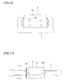
- Fig. 5 shows a structural example of the end plate 24.
- Fig. 5(a) is an exploded plan view.
- Fig. 5(b) is an exploded front view.
- Fig. 5(c) is a side view.
- the same reference numerals as those in Figs. 1 to 4 denote the same or corresponding portions. The same shall apply in the other drawings.
- the end plate 24 has an approximately U-shaped configuration in a front view.
- the end plate 24 is formed from a pair of split parts 24-1 and 24-2 that are splittable to left and right in the width direction at the opening of the end plate 24.
- One split part 24-1 of the end plate 24 has a positioning pin 26 projecting from a parting surface a thereof.
- a positioning hole 27 fittable with the positioning pin 26 is provided in a parting surface b of the other split part 24-2.
- securing screw holes 28-1 and 28-2 are provided in the split parts 24-1 and 24-2, respectively.
- the two split parts 24-1 and 24-2 are brought toward each other from both sides of the track rail 1 so that the parting surfaces a and b approach each other.
- the positioning pin 26 is fitted into the positioning hole 27, and the parting surfaces a and b are brought into coincidence with each other, thereby forming an end plate assembly.
- the end plate assembly is secured to one end of the moving block body 21 by using securing pins passed through the securing screw holes 28-1 and 28-2 of the split parts 24-1 and 24-2.
- reference numeral 29 denotes an oil hole.
- the split parts 24-1 and 24-2, which constitute the end plate 24, are brought toward each other from both sides of the track rail 1. Then, the positioning pin 26 is fitted into the positioning hole 27, and the parting surfaces a and b are brought into coincidence with each other to form an end plate assembly. Accordingly, the split parts 24-1 and 24-2 can be positioned with respect to each other with high accuracy. Further, the end plate assembly is secured to one end of the moving block body 21 by using securing screws passed through the securing screw holes 28-1 and 28-2. Thus, the split parts 24-1 and 24-2 can be positioned and secured with high accuracy, and no displacement will occur during use.
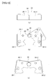
- Fig. 6 shows another structural example of the end plate 24.
- Fig. 6(a) is a plan view.
- Fig. 6(b) is a front view.
- Fig. 6(c) is a side view.
- Fig. 6(d) is a front view of a positioning member.
- Fig. 6(e) is a plan view of the positioning member.
- the end plate 24 is formed from a pair of split parts 24-1 and 24-2 that are splittable to left and right in the width direction at the opening of the end plate 24.
- the respective tops of the split parts 24-1 and 24-2 are provided with positioning holes 30-1 and 30-2 at respective positions a predetermined distance away from parting surfaces a and b.
- a positioning member 31 is made from a metal plate or the like. The positioning member 31 is bent at both ends thereof into a U-shape in a front view so that the end portions of the positioning member 31 can be fitted into the positioning holes 30-1 and 30-2, respectively.
- the split parts 24-1 and 24-2 are brought toward each other from both sides of the track rail 1 until the parting surfaces a and b coincide with each other.
- the bent end portions of the positioning member 31 are fitted into the positioning holes 30-1 and 30-2 to form an end plate assembly.
- the end plate assembly is secured to one end of the moving block body 21 by using securing screws passed through the securing screw holes 28-1 and 28-2.
- the split parts 24-1 and 24-2 are positioned with respect to each other with high accuracy, and in this state the end plate assembly is secured to one end of the moving block body 21. Therefore, no displacement will occur during use, as in the case of the first embodiment.
- the positioning holes 30-1 and 30-2 are provided on the respective tops of the split parts 24-1 and 24-2, and the positioning member 31 is fitted into the positioning holes 30-1 and 30-2 from thereabove.
- the arrangement may, however, be such that the positioning holes 30-1 and 30-2 are provided on the respective sides of the split parts 24-1 and 24-2, and the positioning member 31 is fitted into the positioning holes 30-1 and 30-2 from sideward directions.
- Fig. 7 shows still another structural example of the end plate 24.
- Fig. 7(a) is a plan view of the end plate 24 and a retaining member 32.
- Fig. 7(b) is a side view of the end plate 24.
- Fig. 7(c) is a front view of the end plate 24.
- Fig. 7(d) is a front view of the retaining member 32.
- the end plate 24 is formed from a pair of split parts 24-1 and 24-2 that are splittable to left and right in the width direction at the opening of the end plate 24.
- the split parts 24-1 and 24-2 are provided with respective securing screw holes 28-1 and 28-2.
- the retaining member 32 is made from a metal plate or the like.
- the retaining member 32 is bent at both ends thereof into a U-shape.
- the split parts 24-1 and 24-2 are brought toward each other from both sides of the track rail 1 until their parting surfaces a and b contact and coincide with each other.
- the split parts 24-1 and 24-2 are fitted between the opposite ends of the retaining member 32, whereby the split parts 24-1 and 24-2 are positioned with respect to each other to form an end plate assembly.
- the end plate assembly is secured to one end of the moving block body 21 by using securing screws passed through the securing screw holes 28-1 and 28-2.
- the split parts 24-1 and 24-2 are positioned with respect to each other with high accuracy, and in this state they are secured to one end of the moving block body 21. Therefore, no displacement will occur during use, as in the case of the above-described first and second embodiments.
- the retaining member 32 is fitted to the end plate assembly from the front thereof, it should be noted that the retaining member 32 may be fitted to the end plate assembly from the back thereof or from thereabove.
- Fig. 8 shows a further structural example of the end plate 24.
- Fig. 8(a) is an exploded plan view.
- Fig. 8(b) is a front view.
- Fig. 8(c) is a side view.
- the end plate 24 is formed from a pair of split parts 24-1 and 24-2 that are splittable to left and right at a parting surface consisting of axial surfaces (extending in the travel direction) c and d and widthwise surfaces e perpendicular to the axial direction.
- a recess f is provided at the intersection of the axial surface c and the widthwise surface e of the split part 24-1, and a projection g is provided at the intersection of the axial surface d and the widthwise surface e of the split part 24-1.
- a projection h is provided at the intersection of the axial surface c and the widthwise surface e of the split part 24-2.
- the projection h is to be fitted into the recess f.
- a recess i is provided at the intersection of the axial surface d and the widthwise surface e of the split part 24-2.
- the recess i is to be fitted with the projection g.
- the split parts 24-1 and 24-2 are brought toward each other from both sides of the track rail 1 until their respective axial surfaces c, axial surfaces d and widthwise surfaces e contact and coincide with each other, whereby the recess f and the projection h are fitted to each other, and so are the projection g and the recess i, thereby forming an end plate assembly. Then, the end plate assembly is secured to one end of the moving block body 21 by using securing screws passed through the securing screw holes 28-1 and 28-2.
- the split parts 24-1 and 24-2 are positioned with respect to each other with high accuracy, and in this state they are secured to one end of the moving block body 21. Accordingly, no displacement will occur during use, as in the case of the first to third embodiments.
- the combination of surfaces at which the end plate 24 is splittable into the pair of split parts 24-1 and 24-2 is not necessarily limited to that in the above-described embodiment. Any structure may be used in which the split parts 24-1 and 24-2 have a recess and a projection that are fitted to each other when the split parts 24-1 and 24-2 are joined together in such a way that their surfaces contact and coincide with each other, thereby preventing the split parts 24-1 and 24-2 from moving relative to each other in the width direction.
- Fig. 9 shows a still further structural example of the end plate 24.
- Fig. 9(a) is a front view.
- Fig. 9(b) is a front view of one split part.
- Fig. 9(c) is a front view of the other split part.
- an end plate 24 having an oil hole 29 is splittable into two at a parting surface j crossing the oil hole 29 at a position a predetermined distance away from the center of the oil hole 29. That is, the end plate 24 is formed from a pair of split parts 24-1 and 24-2 as shown in Figs. 9(b) and 9(c).
- a columnar blank plug 33 is inserted into the oil hole 29 of the split part 24-2.
- the split parts 24-1 and 24-2 are brought toward each other from both sides of the track rail 1 so that their respective parting surfaces j approach each other, whereby the oil hole 29 of the split part 24-1 is fitted to the blank plug 33 in the split part, and at the same time, the parting surfaces j are brought into coincidence with each other, thereby forming an end plate assembly.
- the end plate assembly is secured to one end of the moving block body 21 by using securing screws passed through the securing screw holes 28-1 and 28-2.
- the split parts 24-1 and 24-2 can be positioned with respect to each other with high accuracy, and in this state they are secured to one end of the moving block body 21. Therefore, no displacement will occur during use, as in the case of the first to fourth embodiments.
- the present invention has been described with regard to a guide apparatus in which the moving block 2 is assembled astride the track rail 1, by way of example.
- the present invention is, however, not necessarily limited to guide apparatus having such a structure.
- the present invention may also be applied to a guide apparatus in which, as shown in Fig. 10, a moving block 2 is assembled into the opening of a track rail 1 with a U-shaped sectional configuration. That is, in this type of guide apparatus, the moving block body 21 per se can be assembled into the track rail 1 from thereabove, but end plates attached to both ends of the moving block body 21 in the travel direction have a width larger than the width L4 of the opening of the track rail 1.
- the moving block 2 can be easily assembled into the opening of the track rail 1 by using end plates each comprising a pair of split parts 24-1 and 24-2 arranged as shown in Figs. 5 to 9. That is, the split parts 24-1 and 24-2 are positioned with respect to each other in the opening of the track rail 1 and connected together into an end plate assembly. Thereafter, the end plate assembly is secured to one end of the moving block body 21. By doing so, the moving block 2 can be easily assembled into the track rail 1 at an intermediate part thereof even if the track rail 1 has an endless annular shape.
- Fig. 11 is a plan view showing still another structural example of the guide apparatus according to the present invention.
- the guide apparatus has a track rail 1 whose rolling element rolling grooves 11-1 and 11-2 (not shown) and rolling element rolling grooves 12-1 and 12-2 (not shown) turn uphill at both ends of the track rail 1.
- a conventional moving block 2 cannot be assembled onto the track rail 1 from either end thereof. Therefore, the moving block body 21 is arranged so that it can be assembled onto the track rail 1 from thereabove, as shown in Fig. 2.
- the end plates 24 and 25 are each formed from a pair of split parts 24-1 and 24-2 arranged as shown in Figs. 5 to 9. By doing so, the moving block 2 can be easily assembled onto the track rail 1.
- Fig. 12 shows a still further structural example of the end plate 24.
- Fig. 12(a) is a plan view.
- Fig. 12(b) is a front view.
- Fig. 12(c) is a front view showing the end plate in a state where the split parts are open.
- the split parts 24-1 and 24-2 are partly connected to each other at a joint 34 so that the opening of the end plate 24 can be enlarged in the width direction.
- the split parts 24-1 and 24-2 are provided with respective securing screw holes 28-1 and 28-2.
- the joint 34 is sufficiently elastic to allow the split parts 24-1 and 24-2 to rotate about the joint 34 so as to enlarge the opening of the end plate 24.
- the split parts 24-1 and 24-2 of the end plate 24 are rotated clockwise and counterclockwise, respectively, about the joint 34 to enlarge the opening of the end plate 24 as shown in Fig. 12(c).
- the end plate 24 is mounted astride the track rail 1.
- the split parts 24-1 and 24-2 are brought toward each other to form an end plate assembly.
- the end plate assembly is secured to one end of the moving block body 21 by using securing screws passed through the securing screw holes 28-1 and 28-2.
- the split parts 24-1 and 24-2 are positioned with respect to each other with high accuracy, and in this state they are secured to one end of the moving block body 21. Therefore, no displacement will occur during use, as in the case of the first to sixth embodiments.
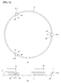
- Fig. 13 shows a further structural example of the guide apparatus according to the present invention.
- Fig. 13(a) is a plan view of the guide apparatus in this embodiment.
- Fig. 13(b) is a side view of the guide apparatus as used in a rotary table system.
- the guide apparatus in this embodiment differs from the guide apparatus shown in Fig. 1 in that, as shown in Fig. 13(a), a plurality (three in the illustrated example) of moving blocks 2-1 to 2-3 are movably attached to an annular track rail 1.
- the moving blocks 2-1 to 2-3 each use a moving block body 21 having the same structure as that shown in Fig. 2. End plates 24 and 25 secured to both axial ends of the moving block body 21 have the same structure as that of any of the structural examples shown in Figs. 5 to 9 and 12.
- a rotary table system can be constructed by mounting a table 35 onto the moving blocks 2-1 to 2-3 as shown in Fig. 13(b).
- the rotary table system arranged as stated above can bear a load near the loading point and is therefore satisfactorily resistant to turning moment.
- Figs. 14 and 15 show a still further structural example of the guide apparatus according to the present invention.
- Fig. 14(a) is a plan view of the guide apparatus in this embodiment.
- Fig. 14(b) is a sectional view taken along the line B-B in Fig. 14(a).
- Fig. 15 is an enlarged view of part C of Fig. 14(b).
- the guide apparatus in this embodiment has an endless annular track rail 4 and a plurality (three in the illustrated example) of moving blocks 5 (6) movably attached to each of the upper and lower sides of the track rail 4.
- the track rail 4 is approximately rectangular in a section perpendicular to the axial direction (i.e. the travel direction of the moving blocks).
- the track rail 4 has recesses in the respective centers of the left and right sides thereof.
- the track rail 4 has ridges 41 and 42 on the left and right sides of the top and bottom thereof.
- Rolling element rolling grooves 41-1 and 41-2 along which rolling elements (balls in the illustrated example) roll are formed on the upper and lower ridges 41 on the right side (inner peripheral side) of the track rail 4, and rolling element rolling grooves 42-1 and 42-2 are formed on the upper and lower ridges 42 on the left side (outer peripheral side) of the track rail 4.
- the moving block 5 has a moving block body 51 with a U-shaped sectional configuration as a main body thereof.
- the moving block body 51 has skirt portions 52 and 53 formed on the left and right sides thereof.
- the skirt portions 52 and 53 face each other across the opening of the U-shaped moving block body 51.
- the moving block 6 has a moving block body 61 with a U-shaped sectional configuration as a main body thereof.
- the moving block body 61 has skirt portions 62 and 63 formed on the left and right sides thereof.
- the skirt portions 62 and 63 face each other across the opening of the U-shaped moving block body 61.
- the width of the opening of each of the moving block bodies 51 and 61 is larger than the width between the respective distal ends of the ridges 41 and 42 of the track rail 4. That is, the moving block bodies 51 and 61 can be assembled onto the track rail 1 from thereabove and from therebelow, respectively.
- the inner surface of the skirt portion 52 of the moving block body 51 is provided with an axial rolling element rolling groove 52-1 facing opposite the rolling element rolling groove 41-1 of the track rail 4.
- the inner surface of the skirt portion 53 of the moving block body 51 is provided with an axial rolling element rolling groove 53-1 facing opposite the rolling element rolling groove 42-1 of the track rail 4.
- the inner surface of the skirt portion 62 of the moving block body 61 is provided with an axial rolling element rolling groove 62-1 facing opposite the rolling element rolling groove 41-2 of the track rail 4.
- the inner surface of the skirt portion 63 of the moving block body 61 is provided with an axial rolling element rolling groove 63-1 facing opposite the rolling element rolling groove 42-2 of the track rail 4.
- skirt portions 52 and 53 of the moving block body 51 are provided with rolling element relief bores 52-2 and 53-2 associated with the rolling element rolling grooves 52-1 and 53-1, respectively.
- skirt portion 62 of the moving block body 61 are provided with rolling element relief bores 62-2 and 63-2 associated with the rolling element rolling grooves 62-1 and 63-1, respectively.
- End plates 24' and 25' are provided at both ends of each of the moving block bodies 5 and 6 in the axial direction (travel direction) thereof.
- the end plates 24' and 25' have approximately the same structure as that of any of the structural examples shown in Figs. 5 to 9 and 12.
- the end plate 24' is formed from an elastic material, e.g. an elastic resin material.
- an elastic material e.g. an elastic resin material.
- the end plate 24' placed on the top of the track rail 4 is pressed in the direction indicated by the arrow F so that the track rail 4 will be fitted into the opening of the end plate 24'. Consequently, the end plate 24' is elastically deformed as shown by the dashed-and-dotted line E at a position where the projections 24-1 and 24-2 pass the upper end portion of the track rail 4. Thereafter, the end plate 24' is fitted in the position shown by the solid line. More specifically, when the end plate 24' is fitted onto the track rail 4 from thereabove, the rolling element scooping projections 24'-1 and 24'-2 abut on the upper end of the track rail 4.
- the spacing between the projections 24'-1 and 24'-2 widens, as shown by the dashed-and-dotted line, to a sufficiently wide spacing (L5) to allow passage of the upper end of the track rail 4. Further pressing the end plate 24' enables the projections 24'-1 and 24'-2 of the end plate 24' to be fitted into the rolling element rolling grooves 41-1 and 42-1 of the track rail 4, as shown by the solid line. Thus, the end plate 24' is assembled onto the track rail 4.
- the end plate 24' of the guide apparatus is formed from an elastic material so that the portion of the opening that has the smallest width is expandable within the elastic deformation range to enable the upper end portion of the track rail 4 to pass therethrough, thereby allowing the end plate 24' to be readily assembled onto the track rail 4.
- the end plates 24' which have a one-piece structure as shown in Fig. 16, onto the upper and lower sides of the track rail 4 as shown in Fig. 17.
- Fig. 17 is an enlarged sectional view as seen in the direction of the arrow D-D in Fig. 14(a).
- the end plates 25' can also be assembled onto the upper and lower sides of the track rail 4 by forming them from an elastic material as in the case of the end plates 24', although an illustration thereof is omitted.
- Fig. 18 shows an example of use of a guide apparatus arranged as shown in Figs. 14 to 15.
- a robot 80 is installed with a guide apparatus 70 interposed between bases 81 and 82.
- the guide apparatus 70 has a plurality of moving blocks 5 and 6 assembled onto the upper and lower sides of a track rail 4.
- the track rail 4 and the base 82 can swivel independently of each other. Accordingly, if a tool table 83, for example, is attached to the track rail 4, tools or the like can be changed without rotating the arm of the robot 80. If the robot 80 and the tool table 83 are rotated toward each other, the tool change time can be reduced.
- the present invention is not necessarily limited to the above-described embodiments but can be modified in a variety of ways.
- the balls 3 are used as the rolling elements in the foregoing embodiments, the rolling elements are not necessarily limited to balls but may be rollers.
Landscapes
- Engineering & Computer Science (AREA)
- General Engineering & Computer Science (AREA)
- Mechanical Engineering (AREA)
- Bearings For Parts Moving Linearly (AREA)
Abstract
A guide apparatus has a standard end plate split into a pair of split parts that can be positioned with respect to each other with high accuracy and firmly secured to each axial end of a moving block body without fear of displacement during use.
The guide apparatus has a moving block relatively movably attached to a track rail. The moving block body has in a section perpendicular to the axial direction a geometry that allows the moving block body to be assembled to the track rail at an intermediate part of the track rail. The end plate 24 consists essentially of a pair of split parts 24-1, 24-2 that are splittable to right and left in the width direction of the end plate. One split part 24-1 has a positioning pin 26 projecting from a parting surface thereof. A positioning hole 27 fittable with the positioning pin is provided in a parting surface of the other split part 24-2. The positioning pin is fitted into the positioning hole to form an end plate 24-2 assembly. The end plate assembly is secured to one end of the moving block body in the direction of relative movement by using securing screws 28-1, 28-2 passed through securing screw holes provided in the split parts 24-1, 24-2, respectively.
Description
- The present invention relates to a guide apparatus having a track rail and a moving block relatively movably attached to the track rail with a plurality of rolling elements (balls or rollers) interposed therebetween. More particularly, the present invention relates to a guide apparatus suitable for use in a case where a moving block is assembled to a track rail having an endless annular shape or to a track rail having a rolling element rolling surface that turns uphill at both ends thereof. It should be noted that the term "relatively movable" as used herein means that the moving block and the track rail are movable relative to each other, such as in a case where the track rail is fixed, and the moving block is movable, and in a case where the moving block is fixed, and the track rail is movable.
- There is a guide apparatus having a moving block relatively movably attached to a track rail with a multiplicity of rolling elements interposed therebetween. In such a guide apparatus, conventionally, the moving block cannot be assembled onto the track rail from thereabove (so that the moving block is mounted astride the track rail). Therefore, the moving block is assembled onto the track rail from an end of the rail. In a case where the track rail is formed in an endless annular shape, or in a case where the track rail has a rolling element rolling surface that turns uphill at both ends thereof, however, the moving block cannot be assembled to the track rail from an end of the rail. Accordingly, the conventional practice is to form an intermediate portion of a predetermined length of the track rail as a separate removable part. When the moving block is to be assembled to the track rail, the removable part portion is removed from the track rail, and the moving block is assembled to the track rail from an end of an intermediate part of the track rail from which the removable part portion has been removed. Thereafter, the removable part portion is returned to the previous position and secured to the track rail.
- It is also conceivable to arrange the moving block body so that it can be assembled to the track rail from thereabove, and to split each end plate into a pair of split parts in a width direction (i.e. a direction perpendicular to the direction of travel) as disclosed in
Patent Document 1. In assembly process, after the moving block body has been assembled to the track rail, an end plate formed from a pair of split parts is secured to each end of the moving block body in the travel direction. With this arrangement, the moving block can be assembled to the track rail even if it has an endless annular shape or it has a rolling element rolling surface that turns uphill at both ends thereof.Patent Document 2 discloses a guide apparatus including a moving block having a special structure so that the moving block can be attached to and detached from an endless annular track rail sideways.
Patent Document 1: -
Japanese Patent Application Unexamined Publication (KOKAI) No. Sho 58-142017 -
Japanese Patent Application Unexamined Publication (KOKAI) No. Hei 8-21440 - According to the first-mentioned conventional method, each end plate is split into a pair of split parts in the width direction, and after the moving block body has been assembled to the track rail, an end plate formed from a pair of split parts is secured to each end of the moving block body in the travel direction, as disclosed in
Patent Document 1. This method has the problem that it is difficult or impossible to position the split parts of the end plate with respect to each other with high accuracy. Even if the end plate split parts have been positioned with respect to each other accurately, displacement is likely to occur during use. The guide apparatus disclosed inPatent Document 2 needs to use a moving block body and end plates having special structures in order to allow the moving block to be attached to and detached from the track rail sideways. Conventional standard moving block body and end plates cannot be used in the prior art apparatus. An object of the present invention is to eliminate the above-described problems with the prior art and to provide a guide apparatus using a standard end plate split into a pair of split parts that can be positioned with respect to each other with high accuracy and firmly secured to each axial end of a moving block body without fear of displacement during use. - To attain the above-described object, the present invention is applied to a guide apparatus including a track rail having a longitudinally extending rolling element rolling surface. A moving block is relatively movably attached to the track rail. The moving block has a moving block body with a load rolling element rolling surface that forms a load rolling element rolling passage in cooperation with the rolling element rolling surface. The moving block body further has a rolling element relief bore associated with the load rolling element rolling surface. An end plate is attached to each end of the moving block body in the direction of relative movement of the moving block. The end plate has a rolling element direction change passage that forms a rolling element recirculation passage in cooperation with the load rolling element rolling passage and the rolling element relief bore. A plurality of rolling elements are disposed in the rolling element recirculation passage so as to recirculate in response to the relative movement of the track rail and the moving block. According to a first feature of the present invention, the moving block body has in a section perpendicular to the axial direction a geometry that allows the moving block body to be assembled to the track rail at an intermediate part of the track rail. The end plate consists essentially of a pair of split parts that are splittable to right and left in the width direction of the end plate. The split parts of the end plate are connected to each other into an end plate assembly with a high positioning accuracy by a connecting mechanism. The end plate assembly is secured to one end of the moving block body in the direction of relative movement by a securing mechanism.
- According to a second feature of the present invention, the connecting mechanism in the guide apparatus according to the first feature of the present invention includes a positioning pin projecting from a parting surface of one split part of the end plate. A positioning hole fittable with the positioning pin is provided in a parting surface of the other split part. The positioning pin is fitted into the positioning hole to form the end plate assembly. The securing mechanism includes securing screws and securing screw holes respectively provided in the split parts of the end plate. The securing screws are passed through the securing screw holes to secure the end plate assembly to one end of the moving block body in the direction of relative movement.
- According to a third feature of the present invention, the connecting mechanism in the guide apparatus according to the first feature of the present invention includes positioning holes provided in the split parts of the end plate at respective positions a predetermined distance away from respective parting surfaces of the split parts. The connecting mechanism further includes a positioning member bent at both ends thereof into a U-shape so that both end portions of the positioning member are fittable into the positioning holes, respectively. The split parts are brought into contact with each other so that the parting surfaces coincide with each other, and both end portions of the positioning member are fitted into the respective positioning holes of the split parts to form the end plate assembly. The securing mechanism includes securing screws and securing screw holes respectively provided in the split parts of the end plate. The securing screws are passed through the securing screw holes to secure the end plate assembly to one end of the moving block body in the direction of relative movement.
- According to a fourth feature of the present invention, the connecting mechanism in the guide apparatus according to the first feature of the present invention includes a retaining member bent at both ends thereof into a U-shape. The split parts are brought into contact with each other so that parting surfaces of the split parts coincide with each other. In this state, the split parts are fitted between the opposite end portions of the retaining member to form the end plate assembly. The securing mechanism includes securing screws and securing screw holes respectively provided in the split parts of the end plate. The securing screws are passed through the securing screw holes to secure the end plate assembly to one end of the moving block body in the direction of relative movement.
- According to a fifth feature of the present invention, the connecting mechanism in the guide apparatus according to the first feature of the present invention includes a recess and a projection provided on respective parting surfaces of the split parts of the end plate. The recess and the projection are fittable to each other to prevent the split parts from moving relative to each other in the width direction. The split parts are joined together so that the parting surfaces coincide with each other and the recess and the projection are fitted to each other, thereby forming the end plate assembly. The securing mechanism includes securing screws and securing screw holes respectively provided in the split parts of the end plate. The securing screws are passed through the securing screw holes to secure the end plate assembly to one end of the moving block body in the direction of relative movement.
- According to a sixth feature of the present invention, the connecting mechanism in the guide apparatus according to the first feature of the present invention includes a blank plug provided in one of the split parts of the end plate such that a part of the blank plug projects from a parting surface of the one of the split parts. A recess fittable with the projecting part of the blank plug is provided in a parting surface of the other of the split parts. The split parts are joined together so that the parting surfaces coincide with each other and the projecting part of the blank plug is fitted into the recess, thereby forming the end plate assembly. The securing mechanism includes securing screws and securing screw holes respectively provided in the split parts of the end plate. The securing screws are passed through the securing screw holes to secure the end plate assembly to one end of the moving block body in the direction of relative movement.
- According to a seventh feature of the present invention, the end plate in the guide apparatus according to the first feature of the present invention has an approximately U-shaped configuration in a section perpendicular to the axial direction and is assembled astride the track rail. The connecting mechanism is arranged such that the split parts are partly connected to each other at a joint. In assembly process, the split parts are rotated about the joint so as to enlarge the opening of the end plate in the width direction. In this state, the end plate is assembled astride the track rail to form the end plate assembly. The securing mechanism includes securing screws and securing screw holes respectively provided in the split parts of the end plate. The securing screws are passed through the securing screw holes to secure the end plate assembly to one end of the moving block body in the direction of relative movement.
- According to an eighth feature of the present invention, the track rail in the guide apparatus according to any of the first to seventh features of the present invention has an endless annular shape.
- According to a ninth feature of the present invention, the track rail in any of the first to seventh features of the present invention has the rolling element rolling surface that turns uphill at both ends thereof.
- In addition, the present invention is applied to a guide apparatus including a track rail having a longitudinally extending rolling element rolling surface. A moving block is relatively movably attached to the track rail. The moving block has a moving block body with a load rolling element rolling surface that forms a load rolling element rolling passage in cooperation with the rolling element rolling surface. The moving block body further has a rolling element relief bore associated with the load rolling element rolling surface. An end plate is attached to each end of the moving block body in the direction of relative movement of the moving block. The end plate has a rolling element direction change passage that forms a rolling element recirculation passage in cooperation with the load rolling element rolling passage and the rolling element relief bore. A plurality of rolling elements are disposed in the rolling element recirculation passage so as to recirculate in response to the relative movement of the track rail and the moving block. According to a tenth feature of the present invention, the moving block body has in a section perpendicular to the axial direction a geometry that allows the moving block body to be assembled to the track rail at an intermediate part of the track rail. The end plate has an approximately U-shaped configuration in a section perpendicular to the axial direction and is assembled astride the track rail. The end plate is formed from an elastic material so that the width of the opening of the end plate is expandable by elastic deformation to allow the end plate to be assembled onto the track rail. The end plate assembled onto the track rail is secured to one end of the moving block body in the direction of relative movement by a securing mechanism.
- According to the first to ninth features of the present invention, each end plate is formed from a pair of split parts splittable to right and left in the width direction. Therefore, the end plate need not be assembled to the track rail from one end of the track rail but can be easily assembled thereto sideways at an intermediate part of the track rail. Moreover, because the split parts of the end plate are secured to one end of the moving block after the split parts have been positioned with respect to each other with high accuracy, the split parts can be mounted without fear of displacement during use. Accordingly, the moving block can be easily assembled to the track rail at an intermediate part thereof even if the track rail has an endless annular shape, or if the track rail has a rolling element rolling surface that turns uphill at both ends thereof, or, further, if it is difficult to assemble the moving block to the track rail from an end thereof owing to an obstacle or the like.
- According to the tenth feature of the present invention, the end plate is formed from an elastic material so that the width of the opening of the end plate is expandable by elastic deformation to allow the end plate to be assembled onto the track rail. Therefore, the end plate is simple in structure and easy to assemble onto the track rail. Accordingly, the moving block can be easily assembled to the track rail at an intermediate part thereof even if the track rail has an endless annular shape, or if the track rail has a rolling element rolling surface that turns uphill at both ends thereof, or, further, if it is difficult to assemble the moving block to the track rail from an end thereof owing to an obstacle or the like, as in the case of the above.
- Embodiments of the present invention will be described below with reference to the accompanying drawings. Figs. 1 to 4 show the structure of a guide apparatus according to the present invention. Fig. 1 is a plan view. Fig. 2 is a sectional view taken along the line A-A in Fig. 1. Fig. 3 is a front view of a conventional end plate. Fig. 4 is a plan view of a moving block. As shown in the figures, the guide apparatus according to the present invention has an endless
annular track rail 1 and a movingblock 2 movably attached thereto. Thetrack rail 1 is approximately rectangular in a section perpendicular to the axial direction (i.e. the travel direction of the moving block 2). Thetrack rail 1 has recesses in the respective centers of the left and right sides thereof. Thetrack rail 1 hasridges ridge 11, and rolling element rolling grooves 12-1 and 12-2 are formed on the upper and lower corners of theridge 12. - The moving
block 2 has a movingblock body 21 with a U-shaped sectional configuration as a main body thereof. The movingblock body 21 hasskirt portions skirt portions block body 21. The width L1 of the opening of the moving block body 21 (i.e. the spacing between the mutually opposing inner surfaces of theskirt portions 22 and 23) is larger than the width L2 between the respective distal ends of theridges block body 21 can be assembled onto thetrack rail 1 from thereabove (or sideways). The inner surface of theskirt portion 22 of the movingblock body 21 is provided with axial load rolling element rolling grooves 22-1 and 22-2 facing opposite the rolling element rolling grooves 11-1 and 11-2 of thetrack rail 1. The inner surface of theskirt portion 23 is provided with axial load rolling element rolling grooves 23-1 and 23-2 facing opposite the rolling element rolling grooves 12-1 and 12-2 of thetrack rail 1. In addition, theskirt portion 22 is provided with rolling element relief bores 22-3 and 22-4 respectively associated with the load rolling element rolling grooves 22-1 and 22-2. Theskirt portion 23 is provided with rolling element relief bores 23-3 and 23-4 respectively associated with the load rolling element rolling grooves 23-1 and 23-2. - The rolling element rolling grooves 11-1 and 11-2 of the
track rail 1 and the load rolling element rolling grooves 22-1 and 22-2 of the movingblock body 21 form load rolling element rolling passages R1 and R2, respectively. The rolling element rolling grooves 12-1 and 12-2 of thetrack rail 1 and the load rolling element rolling grooves 23-1 and 23-2 of the movingblock body 21 form load rolling element rolling passages R3 and R4, respectively.End plates block body 21 in the travel direction (axial direction) thereof. Theend plates block 2 moves, a multiplicity of rolling elements (balls) 3 roll and recirculate through rolling element recirculation passages (there are four rolling element recirculation passages in the illustrated example) respectively formed from the load rolling element rolling passages R1, R2, R3 and R4, the rolling element relief bores 22-3, 22-4, 23-3 and 23-4 and the direction change passages R5, R6, R7 and R8. - As stated above, the width L1 of the opening of the moving
block body 21 is larger than the width L2 between the distal ends of theridges block body 21 can be assembled onto thetrack rail 1 from thereabove (or sideways). Accordingly, even if thetrack rail 1 has an endless annular shape, it is easy to assemble the movingblock body 21 onto thetrack rail 1. In contrast, theend plates ridges end plates track rail 1 from thereabove (or sideways). Under these circumstances, the present invention made the following improvements to theend plates track rail 1 from thereabove. It should be noted that the following description is made of theend plate 24, but the same is the case with theend plate 25. - Fig. 5 shows a structural example of the
end plate 24. Fig. 5(a) is an exploded plan view. Fig. 5(b) is an exploded front view. Fig. 5(c) is a side view. In these figures, the same reference numerals as those in Figs. 1 to 4 denote the same or corresponding portions. The same shall apply in the other drawings. As shown in Figs. 5(a), 5(b) and 5(c), theend plate 24 has an approximately U-shaped configuration in a front view. Theend plate 24 is formed from a pair of split parts 24-1 and 24-2 that are splittable to left and right in the width direction at the opening of theend plate 24. One split part 24-1 of theend plate 24 has apositioning pin 26 projecting from a parting surface a thereof. Apositioning hole 27 fittable with thepositioning pin 26 is provided in a parting surface b of the other split part 24-2. Further, securing screw holes 28-1 and 28-2 are provided in the split parts 24-1 and 24-2, respectively. The two split parts 24-1 and 24-2 are brought toward each other from both sides of thetrack rail 1 so that the parting surfaces a and b approach each other. Then, thepositioning pin 26 is fitted into thepositioning hole 27, and the parting surfaces a and b are brought into coincidence with each other, thereby forming an end plate assembly. Next, the end plate assembly is secured to one end of the movingblock body 21 by using securing pins passed through the securing screw holes 28-1 and 28-2 of the split parts 24-1 and 24-2. It should be noted thatreference numeral 29 denotes an oil hole. - As stated above, the split parts 24-1 and 24-2, which constitute the
end plate 24, are brought toward each other from both sides of thetrack rail 1. Then, thepositioning pin 26 is fitted into thepositioning hole 27, and the parting surfaces a and b are brought into coincidence with each other to form an end plate assembly. Accordingly, the split parts 24-1 and 24-2 can be positioned with respect to each other with high accuracy. Further, the end plate assembly is secured to one end of the movingblock body 21 by using securing screws passed through the securing screw holes 28-1 and 28-2. Thus, the split parts 24-1 and 24-2 can be positioned and secured with high accuracy, and no displacement will occur during use. - Fig. 6 shows another structural example of the
end plate 24. Fig. 6(a) is a plan view. Fig. 6(b) is a front view. Fig. 6(c) is a side view. Fig. 6(d) is a front view of a positioning member. Fig. 6(e) is a plan view of the positioning member. Theend plate 24 is formed from a pair of split parts 24-1 and 24-2 that are splittable to left and right in the width direction at the opening of theend plate 24. The respective tops of the split parts 24-1 and 24-2 are provided with positioning holes 30-1 and 30-2 at respective positions a predetermined distance away from parting surfaces a and b. In addition, the split parts 24-1 and 24-2 are provided with respective securing screw holes 28-1 and 28-2. A positioningmember 31 is made from a metal plate or the like. The positioningmember 31 is bent at both ends thereof into a U-shape in a front view so that the end portions of the positioningmember 31 can be fitted into the positioning holes 30-1 and 30-2, respectively. - The split parts 24-1 and 24-2 are brought toward each other from both sides of the
track rail 1 until the parting surfaces a and b coincide with each other. In this state, the bent end portions of the positioningmember 31 are fitted into the positioning holes 30-1 and 30-2 to form an end plate assembly. Thereafter, the end plate assembly is secured to one end of the movingblock body 21 by using securing screws passed through the securing screw holes 28-1 and 28-2. Thus, the split parts 24-1 and 24-2 are positioned with respect to each other with high accuracy, and in this state the end plate assembly is secured to one end of the movingblock body 21. Therefore, no displacement will occur during use, as in the case of the first embodiment. In this embodiment, the positioning holes 30-1 and 30-2 are provided on the respective tops of the split parts 24-1 and 24-2, and the positioningmember 31 is fitted into the positioning holes 30-1 and 30-2 from thereabove. The arrangement may, however, be such that the positioning holes 30-1 and 30-2 are provided on the respective sides of the split parts 24-1 and 24-2, and the positioningmember 31 is fitted into the positioning holes 30-1 and 30-2 from sideward directions. - Fig. 7 shows still another structural example of the
end plate 24. Fig. 7(a) is a plan view of theend plate 24 and a retainingmember 32. Fig. 7(b) is a side view of theend plate 24. Fig. 7(c) is a front view of theend plate 24. Fig. 7(d) is a front view of the retainingmember 32. Theend plate 24 is formed from a pair of split parts 24-1 and 24-2 that are splittable to left and right in the width direction at the opening of theend plate 24. The split parts 24-1 and 24-2 are provided with respective securing screw holes 28-1 and 28-2. The retainingmember 32 is made from a metal plate or the like. The retainingmember 32 is bent at both ends thereof into a U-shape. - The split parts 24-1 and 24-2 are brought toward each other from both sides of the
track rail 1 until their parting surfaces a and b contact and coincide with each other. In this state, the split parts 24-1 and 24-2 are fitted between the opposite ends of the retainingmember 32, whereby the split parts 24-1 and 24-2 are positioned with respect to each other to form an end plate assembly. In this state, the end plate assembly is secured to one end of the movingblock body 21 by using securing screws passed through the securing screw holes 28-1 and 28-2. Thus, the split parts 24-1 and 24-2 are positioned with respect to each other with high accuracy, and in this state they are secured to one end of the movingblock body 21. Therefore, no displacement will occur during use, as in the case of the above-described first and second embodiments. Although in this embodiment, the retainingmember 32 is fitted to the end plate assembly from the front thereof, it should be noted that the retainingmember 32 may be fitted to the end plate assembly from the back thereof or from thereabove. - Fig. 8 shows a further structural example of the
end plate 24. Fig. 8(a) is an exploded plan view. Fig. 8(b) is a front view. Fig. 8(c) is a side view. Theend plate 24 is formed from a pair of split parts 24-1 and 24-2 that are splittable to left and right at a parting surface consisting of axial surfaces (extending in the travel direction) c and d and widthwise surfaces e perpendicular to the axial direction. A recess f is provided at the intersection of the axial surface c and the widthwise surface e of the split part 24-1, and a projection g is provided at the intersection of the axial surface d and the widthwise surface e of the split part 24-1. A projection h is provided at the intersection of the axial surface c and the widthwise surface e of the split part 24-2. The projection h is to be fitted into the recess f. A recess i is provided at the intersection of the axial surface d and the widthwise surface e of the split part 24-2. The recess i is to be fitted with the projection g. When the split parts 24-1 and 24-2 are joined together so that their respective axial surfaces c, axial surfaces d and widthwise surfaces e contact and coincide with each other, the recess f and the projection h are fitted to each other, and so are the projection g and the recess i. Thus, the split parts 24-1 and 24-2 are positioned with respect to each other in a state where they are prevented from moving relative to each other in the width direction. - The split parts 24-1 and 24-2 are brought toward each other from both sides of the
track rail 1 until their respective axial surfaces c, axial surfaces d and widthwise surfaces e contact and coincide with each other, whereby the recess f and the projection h are fitted to each other, and so are the projection g and the recess i, thereby forming an end plate assembly. Then, the end plate assembly is secured to one end of the movingblock body 21 by using securing screws passed through the securing screw holes 28-1 and 28-2. Thus, the split parts 24-1 and 24-2 are positioned with respect to each other with high accuracy, and in this state they are secured to one end of the movingblock body 21. Accordingly, no displacement will occur during use, as in the case of the first to third embodiments. It should be noted that the combination of surfaces at which theend plate 24 is splittable into the pair of split parts 24-1 and 24-2 is not necessarily limited to that in the above-described embodiment. Any structure may be used in which the split parts 24-1 and 24-2 have a recess and a projection that are fitted to each other when the split parts 24-1 and 24-2 are joined together in such a way that their surfaces contact and coincide with each other, thereby preventing the split parts 24-1 and 24-2 from moving relative to each other in the width direction. - Fig. 9 shows a still further structural example of the
end plate 24. Fig. 9(a) is a front view. Fig. 9(b) is a front view of one split part. Fig. 9(c) is a front view of the other split part. As shown in Fig. 9(a), anend plate 24 having anoil hole 29 is splittable into two at a parting surface j crossing theoil hole 29 at a position a predetermined distance away from the center of theoil hole 29. That is, theend plate 24 is formed from a pair of split parts 24-1 and 24-2 as shown in Figs. 9(b) and 9(c). As shown in Fig. 9(d), a columnarblank plug 33 is inserted into theoil hole 29 of the split part 24-2. - The split parts 24-1 and 24-2 are brought toward each other from both sides of the
track rail 1 so that their respective parting surfaces j approach each other, whereby theoil hole 29 of the split part 24-1 is fitted to theblank plug 33 in the split part, and at the same time, the parting surfaces j are brought into coincidence with each other, thereby forming an end plate assembly. The end plate assembly is secured to one end of the movingblock body 21 by using securing screws passed through the securing screw holes 28-1 and 28-2. Thus, the split parts 24-1 and 24-2 can be positioned with respect to each other with high accuracy, and in this state they are secured to one end of the movingblock body 21. Therefore, no displacement will occur during use, as in the case of the first to fourth embodiments. - In the first to fifth embodiments, the present invention has been described with regard to a guide apparatus in which the moving
block 2 is assembled astride thetrack rail 1, by way of example. The present invention is, however, not necessarily limited to guide apparatus having such a structure. The present invention may also be applied to a guide apparatus in which, as shown in Fig. 10, a movingblock 2 is assembled into the opening of atrack rail 1 with a U-shaped sectional configuration. That is, in this type of guide apparatus, the movingblock body 21 per se can be assembled into thetrack rail 1 from thereabove, but end plates attached to both ends of the movingblock body 21 in the travel direction have a width larger than the width L4 of the opening of thetrack rail 1. Even in such a case, the movingblock 2 can be easily assembled into the opening of thetrack rail 1 by using end plates each comprising a pair of split parts 24-1 and 24-2 arranged as shown in Figs. 5 to 9. That is, the split parts 24-1 and 24-2 are positioned with respect to each other in the opening of thetrack rail 1 and connected together into an end plate assembly. Thereafter, the end plate assembly is secured to one end of the movingblock body 21. By doing so, the movingblock 2 can be easily assembled into thetrack rail 1 at an intermediate part thereof even if thetrack rail 1 has an endless annular shape. - Fig. 11 is a plan view showing still another structural example of the guide apparatus according to the present invention. As shown in the figure, the guide apparatus has a
track rail 1 whose rolling element rolling grooves 11-1 and 11-2 (not shown) and rolling element rolling grooves 12-1 and 12-2 (not shown) turn uphill at both ends of thetrack rail 1. In the guide apparatus having such a structure, a conventional movingblock 2 cannot be assembled onto thetrack rail 1 from either end thereof. Therefore, the movingblock body 21 is arranged so that it can be assembled onto thetrack rail 1 from thereabove, as shown in Fig. 2. Theend plates block 2 can be easily assembled onto thetrack rail 1. - Fig. 12 shows a still further structural example of the
end plate 24. Fig. 12(a) is a plan view. Fig. 12(b) is a front view. Fig. 12(c) is a front view showing the end plate in a state where the split parts are open. As shown in the figures, the split parts 24-1 and 24-2 are partly connected to each other at a joint 34 so that the opening of theend plate 24 can be enlarged in the width direction. The split parts 24-1 and 24-2 are provided with respective securing screw holes 28-1 and 28-2. The joint 34 is sufficiently elastic to allow the split parts 24-1 and 24-2 to rotate about the joint 34 so as to enlarge the opening of theend plate 24. - The split parts 24-1 and 24-2 of the
end plate 24 are rotated clockwise and counterclockwise, respectively, about the joint 34 to enlarge the opening of theend plate 24 as shown in Fig. 12(c). In this state, theend plate 24 is mounted astride thetrack rail 1. Thereafter, the split parts 24-1 and 24-2 are brought toward each other to form an end plate assembly. Then, the end plate assembly is secured to one end of the movingblock body 21 by using securing screws passed through the securing screw holes 28-1 and 28-2. Thus, the split parts 24-1 and 24-2 are positioned with respect to each other with high accuracy, and in this state they are secured to one end of the movingblock body 21. Therefore, no displacement will occur during use, as in the case of the first to sixth embodiments. - Fig. 13 shows a further structural example of the guide apparatus according to the present invention. Fig. 13(a) is a plan view of the guide apparatus in this embodiment. Fig. 13(b) is a side view of the guide apparatus as used in a rotary table system. The guide apparatus in this embodiment differs from the guide apparatus shown in Fig. 1 in that, as shown in Fig. 13(a), a plurality (three in the illustrated example) of moving blocks 2-1 to 2-3 are movably attached to an
annular track rail 1. The moving blocks 2-1 to 2-3 each use a movingblock body 21 having the same structure as that shown in Fig. 2.End plates block body 21 have the same structure as that of any of the structural examples shown in Figs. 5 to 9 and 12. - With the guide apparatus having the above-described structure, a rotary table system can be constructed by mounting a table 35 onto the moving blocks 2-1 to 2-3 as shown in Fig. 13(b). The rotary table system arranged as stated above can bear a load near the loading point and is therefore satisfactorily resistant to turning moment.
- Figs. 14 and 15 show a still further structural example of the guide apparatus according to the present invention. Fig. 14(a) is a plan view of the guide apparatus in this embodiment. Fig. 14(b) is a sectional view taken along the line B-B in Fig. 14(a). Fig. 15 is an enlarged view of part C of Fig. 14(b). The guide apparatus in this embodiment has an endless
annular track rail 4 and a plurality (three in the illustrated example) of moving blocks 5 (6) movably attached to each of the upper and lower sides of thetrack rail 4. Thetrack rail 4 is approximately rectangular in a section perpendicular to the axial direction (i.e. the travel direction of the moving blocks). Thetrack rail 4 has recesses in the respective centers of the left and right sides thereof. Thetrack rail 4 hasridges lower ridges 41 on the right side (inner peripheral side) of thetrack rail 4, and rolling element rolling grooves 42-1 and 42-2 are formed on the upper andlower ridges 42 on the left side (outer peripheral side) of thetrack rail 4. - The moving
block 5 has a movingblock body 51 with a U-shaped sectional configuration as a main body thereof. The movingblock body 51 hasskirt portions skirt portions block body 51. Similarly, the movingblock 6 has a movingblock body 61 with a U-shaped sectional configuration as a main body thereof. The movingblock body 61 hasskirt portions skirt portions block body 61. The width of the opening of each of the movingblock bodies ridges track rail 4. That is, the movingblock bodies track rail 1 from thereabove and from therebelow, respectively. - The inner surface of the
skirt portion 52 of the movingblock body 51 is provided with an axial rolling element rolling groove 52-1 facing opposite the rolling element rolling groove 41-1 of thetrack rail 4. The inner surface of theskirt portion 53 of the movingblock body 51 is provided with an axial rolling element rolling groove 53-1 facing opposite the rolling element rolling groove 42-1 of thetrack rail 4. The inner surface of theskirt portion 62 of the movingblock body 61 is provided with an axial rolling element rolling groove 62-1 facing opposite the rolling element rolling groove 41-2 of thetrack rail 4. The inner surface of theskirt portion 63 of the movingblock body 61 is provided with an axial rolling element rolling groove 63-1 facing opposite the rolling element rolling groove 42-2 of thetrack rail 4. In addition, theskirt portions block body 51 are provided with rolling element relief bores 52-2 and 53-2 associated with the rolling element rolling grooves 52-1 and 53-1, respectively. Similarly, theskirt portion 62 of the movingblock body 61 are provided with rolling element relief bores 62-2 and 63-2 associated with the rolling element rolling grooves 62-1 and 63-1, respectively.End plates 24' and 25' are provided at both ends of each of the movingblock bodies end plates 24' and 25' have approximately the same structure as that of any of the structural examples shown in Figs. 5 to 9 and 12. - If an integrally formed
end plate 24' as shown in Fig. 16 is used as each of theend plates 24' and 25' of the guide apparatus shown in Figs. 14 to 15, theend plate 24' cannot be assembled onto thetrack rail 4 from thereabove because the spacing L6 between rollingelement scooping projections 24'-1 and 24'-2 on the mutually opposing inner walls of the opening of theend plate 24' is smaller than the width L5 (see Fig. 15) of the upper end of the track rail 4 (L6<L5). Therefore, theend plate 24' is formed from an elastic material, e.g. an elastic resin material. In assembly process, as shown in Fig. 17, theend plate 24' placed on the top of thetrack rail 4 is pressed in the direction indicated by the arrow F so that thetrack rail 4 will be fitted into the opening of theend plate 24'. Consequently, theend plate 24' is elastically deformed as shown by the dashed-and-dotted line E at a position where the projections 24-1 and 24-2 pass the upper end portion of thetrack rail 4. Thereafter, theend plate 24' is fitted in the position shown by the solid line. More specifically, when theend plate 24' is fitted onto thetrack rail 4 from thereabove, the rollingelement scooping projections 24'-1 and 24'-2 abut on the upper end of thetrack rail 4. When theend plate 24' is further pressed, the spacing between theprojections 24'-1 and 24'-2 widens, as shown by the dashed-and-dotted line, to a sufficiently wide spacing (L5) to allow passage of the upper end of thetrack rail 4. Further pressing theend plate 24' enables theprojections 24'-1 and 24'-2 of theend plate 24' to be fitted into the rolling element rolling grooves 41-1 and 42-1 of thetrack rail 4, as shown by the solid line. Thus, theend plate 24' is assembled onto thetrack rail 4. - As stated above, the
end plate 24' of the guide apparatus is formed from an elastic material so that the portion of the opening that has the smallest width is expandable within the elastic deformation range to enable the upper end portion of thetrack rail 4 to pass therethrough, thereby allowing theend plate 24' to be readily assembled onto thetrack rail 4. Thus, it becomes possible to assemble theend plates 24', which have a one-piece structure as shown in Fig. 16, onto the upper and lower sides of thetrack rail 4 as shown in Fig. 17. It should be noted that Fig. 17 is an enlarged sectional view as seen in the direction of the arrow D-D in Fig. 14(a). The end plates 25' can also be assembled onto the upper and lower sides of thetrack rail 4 by forming them from an elastic material as in the case of theend plates 24', although an illustration thereof is omitted. - Fig. 18 shows an example of use of a guide apparatus arranged as shown in Figs. 14 to 15. As illustrated in the figure, a
robot 80 is installed with aguide apparatus 70 interposed betweenbases guide apparatus 70 has a plurality of movingblocks track rail 4. With this arrangement, thetrack rail 4 and the base 82 can swivel independently of each other. Accordingly, if a tool table 83, for example, is attached to thetrack rail 4, tools or the like can be changed without rotating the arm of therobot 80. If therobot 80 and the tool table 83 are rotated toward each other, the tool change time can be reduced. - The present invention is not necessarily limited to the above-described embodiments but can be modified in a variety of ways. For example, although the
balls 3 are used as the rolling elements in the foregoing embodiments, the rolling elements are not necessarily limited to balls but may be rollers. -
- [Fig. 1] is a plan view showing a structural example of the guide apparatus according to the present invention.
- [Fig. 2] is a sectional view taken along the line A-A in Fig. 1.
- [Fig. 3] is a diagram showing a structural example of a conventional end plate.
- [Fig. 4] is a diagram showing a structural example of a moving block of the guide apparatus according to the present invention.
- [Fig. 5] is a diagram showing a structural example of a moving block end plate of the guide apparatus according to the present invention (first embodiment).
- [Fig. 6] is a diagram showing another structural example of the moving block end plate of the guide apparatus according to the present invention (second embodiment).
- [Fig. 7] is a diagram showing still another structural example of the moving block end plate of the guide apparatus according to the present invention (third embodiment).
- [Fig. 8] is a diagram showing a further structural example of the moving block end plate of the guide apparatus according to the present invention (fourth embodiment).
- [Fig. 9] is a diagram showing a still further structural example of the moving block end plate of the guide apparatus according to the present invention (fifth embodiment).
- [Fig. 10] is a sectional view showing another structural example of the guide apparatus according to the present invention (sixth embodiment).
- [Fig. 11] is a diagram showing still another structural example of the guide apparatus according to the present invention (seventh embodiment).
- [Fig. 12] is a diagram showing a still further structural example of the moving block end plate of the guide apparatus according to the present invention (eighth embodiment).
- [Fig. 13] is a diagram showing a further structural example of the guide apparatus according to the present invention (ninth embodiment).
- [Fig. 14] is a diagram showing a still further structural example of the guide apparatus according to the present invention (tenth embodiment).
- [Fig. 15] is an enlarged view of part C in Fig. 14(b).
- [Fig. 16] is a diagram showing a still further structural example of the end plate of the guide apparatus according to the present invention (eleventh embodiment).
- [Fig. 17] is an enlarged sectional view as seen in the direction of the arrow D-D in Fig. 14(a).
- [Fig. 18] is a diagram showing a structural example of a system using the guide apparatus according to the present invention.
-
- 1: track rail
- 2: moving block
- 3: rolling element (ball)
- 4: track rail
- 5: moving block
- 6: moving block
- 11: ridge
- 12: ridge
- 21: moving block body
- 22: skirt portion
- 23: skirt portion
- 24: end plate
- 25: end plate
- 24': end plate
- 25': end plate
- 26: positioning pin
- 27: positioning hole
- 28: securing screw hole
- 29: oil hole
- 30: positioning hole
- 31: positioning member
- 32: retaining member
- 33: columnar blank plug
- 34: joint
- 35: table
- 51: moving block body
- 52: skirt portion
- 53: skirt portion
- 61: moving block body
- 62: skirt portion
- 63: skirt portion
- 70: guide apparatus
- 80: robot
- 81: base
- 82: base
- 83: tool table
Claims (22)
- A guide apparatus comprising:a track rail having a longitudinally extending rolling element rolling surface; anda moving block relatively movably attached to said track rail;said moving block having:wherein said moving block body has in a section perpendicular to an axial direction a geometry that allows said moving block body to be assembled to said track rail at an intermediate part of said track rail;a moving block body having a load rolling element rolling surface that forms a load rolling element rolling passage in cooperation with said rolling element rolling surface, said moving block body further having a rolling element relief bore associated with said load rolling element rolling surface;an end plate attached to each end of said moving block body in a direction of relative movement of said moving block, said end plate having a rolling element direction change passage that forms a rolling element recirculation passage in cooperation with said load rolling element rolling passage and rolling element relief bore; anda plurality of rolling elements disposed in said rolling element recirculation passage so as to recirculate in response to relative movement of said track rail and moving block;
said end plate consisting essentially of a pair of split parts that are splittable to right and left in a width direction of said end plate;
wherein the split parts of said end plate are connected to each other into an end plate assembly with a high positioning accuracy by connecting means, and said end plate assembly is secured to one end of said moving block body in the direction of relative movement by securing means. - A guide apparatus according to claim 1, wherein said connecting means comprises:a positioning pin projecting from a parting surface of one of the split parts of said end plate; anda positioning hole fittable with said positioning pin, said positioning hole being provided in a parting surface of the other of said split parts;wherein said positioning pin is fitted into said positioning hole to form said end plate assembly;
said securing means comprising:securing screws; andsecuring screw holes respectively provided in the split parts of said end plate;wherein said securing screws are passed through said securing screw holes to secure said end plate assembly to one end of said moving block body in the direction of relative movement. - A guide apparatus according to claim 1, wherein said connecting means comprises:positioning holes provided in the split parts of said end plate at respective positions a predetermined distance away from respective parting surfaces of said split parts; anda positioning member bent at both ends thereof into a U-shape so that both end portions of said positioning member are fittable into said positioning holes, respectively;wherein said split parts are brought into contact with each other so that the parting surfaces coincide with each other, and both end portions of said positioning member are fitted into the respective positioning holes of the said split parts to form said end plate assembly;
said securing means comprising:securing screws; andsecuring screw holes respectively provided in the split parts of said end plate;wherein said securing screws are passed through said securing screw holes to secure said end plate assembly to one end of said moving block body in the direction of relative movement. - A guide apparatus according to claim 1, wherein said connecting means comprises:a retaining member bent at both ends thereof into a U-shape;wherein said split parts are brought into contact with each other so that parting surfaces of said split parts coincide with each other, and in this state said split parts are fitted between opposite end portions of said retaining member to form said end plate assembly;
said securing means comprising:securing screws; andsecuring screw holes respectively provided in the split parts of said end plate;wherein said securing screws are passed through said securing screw holes to secure said end plate assembly to one end of said moving block body in the direction of relative movement. - A guide apparatus according to claim 1, wherein said connecting means comprises:a recess and a projection provided on respective parting surfaces of the split parts of said end plate, said recess and projection being fittable to each other to prevent said split parts from moving relative to each other in the width direction;wherein said split parts are joined together so that said parting surfaces coincide with each other and said recess and projection are fitted to each other, thereby forming said end plate assembly;
said securing means comprising:securing screws; andsecuring screw holes respectively provided in the split parts of said end plate;wherein said securing screws are passed through said securing screw holes to secure said end plate assembly to one end of said moving block body in the direction of relative movement. - A guide apparatus according to claim 1, wherein said connecting means comprises:a blank plug provided in one of the split parts of said end plate such that a part of said blank plug projects from a parting surface of the one of said split parts; anda recess provided in a parting surface of the other of said split parts, said recess being fittable with the projecting part of said blank plug;wherein said split parts are joined together so that the parting surfaces coincide with each other and the projecting part of said blank plug is fitted into said recess, thereby forming said end plate assembly;
said securing means comprising:securing screws; andsecuring screw holes respectively provided in the split parts of said end plate;wherein said securing screws are passed through said securing screw holes to secure said end plate assembly to one end of said moving block body in the direction of relative movement. - A guide apparatus according to claim 1, wherein said end plate has an approximately U-shaped configuration in a section perpendicular to the axial direction and is assembled astride said track rail;
said connecting means comprising:said split parts that are partly connected to each other at a joint;wherein said split parts are rotated about the joint so as to enlarge an opening of said end plate in the width direction, and in this state said end plate is assembled astride said track rail to form said end plate assembly;
said securing means comprising:securing screws; andsecuring screw holes respectively provided in the split parts of said end plate;wherein said securing screws are passed through said securing screw holes to secure said end plate assembly to one end of said moving block body in the direction of relative movement. - A guide apparatus according to claim 1, wherein said track rail has an endless annular shape.
- A guide apparatus according to claim 2, wherein said track rail has an endless annular shape.
- A guide apparatus according to claim 3, wherein said track rail has an endless annular shape.
- A guide apparatus according to claim 4, wherein said track rail has an endless annular shape.
- A guide apparatus according to claim 5, wherein said track rail has an endless annular shape.
- A guide apparatus according to claim 6, wherein said track rail has an endless annular shape.
- A guide apparatus according to claim 7, wherein said track rail has an endless annular shape.
- A guide apparatus according to claim 1, wherein said track rail has the rolling element rolling surface that turns uphill at both ends thereof.
- A guide apparatus according to claim 2, wherein said track rail has the rolling element rolling surface that turns uphill at both ends thereof.
- A guide apparatus according to claim 3, wherein said track rail has the rolling element rolling surface that turns uphill at both ends thereof.
- A guide apparatus according to claim 4, wherein said track rail has the rolling element rolling surface that turns uphill at both ends thereof.
- A guide apparatus according to claim 5, wherein said track rail has the rolling element rolling surface that turns uphill at both ends thereof.
- A guide apparatus according to claim 6, wherein said track rail has the rolling element rolling surface that turns uphill at both ends thereof.
- A guide apparatus according to claim 7, wherein said track rail has the rolling element rolling surface that turns uphill at both ends thereof.
- A guide apparatus comprising:a track rail having a longitudinally extending rolling element rolling surface; anda moving block relatively movably attached to said track rail;said moving block having:wherein said moving block body has in a section perpendicular to an axial direction a geometry that allows said moving block body to be assembled to said track rail at an intermediate part of said track rail;a moving block body having a load rolling element rolling surface that forms a load rolling element rolling passage in cooperation with said rolling element rolling surface, said moving block body further having a rolling element relief bore associated with said load rolling element rolling surface;an end plate attached to each end of said moving block body in a direction of relative movement of said moving block, said end plate having a rolling element direction change passage that forms a rolling element recirculation passage in cooperation with said load rolling element rolling passage and rolling element relief bore; anda plurality of rolling elements disposed in said rolling element recirculation passage so as to recirculate in response to relative movement of said track rail and moving block;
said end plate having an approximately U-shaped configuration in a section perpendicular to the axial direction and being assembled astride said track rail, said end plate being formed from an elastic material so that a width of an opening of said end plate is expandable by elastic deformation to allow said end plate to be assembled onto said track rail;
wherein said end plate assembled onto said track rail is secured to one end of said moving block body in the direction of relative movement by securing means.
Applications Claiming Priority (1)
| Application Number | Priority Date | Filing Date | Title |
|---|---|---|---|
| PCT/JP2005/005006 WO2006100735A1 (en) | 2005-03-18 | 2005-03-18 | Guide device |
Publications (2)
| Publication Number | Publication Date |
|---|---|
| EP1878931A1 true EP1878931A1 (en) | 2008-01-16 |
| EP1878931A4 EP1878931A4 (en) | 2011-06-29 |
Family
ID=37023432
Family Applications (1)
| Application Number | Title | Priority Date | Filing Date |
|---|---|---|---|
| EP05721156A Withdrawn EP1878931A4 (en) | 2005-03-18 | 2005-03-18 | Guide device |
Country Status (4)
| Country | Link |
|---|---|
| EP (1) | EP1878931A4 (en) |
| KR (1) | KR101238991B1 (en) |
| CN (1) | CN101103206B (en) |
| WO (1) | WO2006100735A1 (en) |
Cited By (1)
| Publication number | Priority date | Publication date | Assignee | Title |
|---|---|---|---|---|
| WO2012093253A1 (en) | 2011-01-07 | 2012-07-12 | Rls Merilna Tehnika D.O.O. | Encoder readhead apparatus |
Families Citing this family (2)
| Publication number | Priority date | Publication date | Assignee | Title |
|---|---|---|---|---|
| CN112503105B (en) * | 2020-11-19 | 2022-06-03 | 芜湖安普机器人产业技术研究院有限公司 | Automatic bead separating device for bearing assembly |
| CN117469299A (en) * | 2023-11-17 | 2024-01-30 | 福建利尼尔智能科技有限公司 | A kind of linear guide rail pair |
Family Cites Families (22)
| Publication number | Priority date | Publication date | Assignee | Title |
|---|---|---|---|---|
| JPS5782209U (en) * | 1980-11-10 | 1982-05-21 | ||
| JPS58142016A (en) | 1982-02-13 | 1983-08-23 | Hiroshi Teramachi | Four-way loaded linear bearing |
| JPS61160060U (en) * | 1985-03-26 | 1986-10-03 | ||
| JPS62101914A (en) * | 1985-10-30 | 1987-05-12 | Tsubakimoto Seiko:Kk | Revolution bearing |
| JPS6197625U (en) | 1985-11-21 | 1986-06-23 | ||
| JPS6388928U (en) * | 1986-11-29 | 1988-06-09 | ||
| JPS6427510U (en) * | 1987-08-11 | 1989-02-16 | ||
| JPH0632484Y2 (en) * | 1988-07-29 | 1994-08-24 | キョーラク株式会社 | Bonded structure of plates |
| JPH062836Y2 (en) * | 1988-12-10 | 1994-01-26 | 株式会社東海理化電機製作所 | Mirror holder for vehicle outer mirror |
| JP2524972Y2 (en) * | 1989-07-12 | 1997-02-05 | 株式会社岡村製作所 | Side connection device between panels |
| JPH058037U (en) * | 1992-07-09 | 1993-02-02 | 株式会社椿本精工 | Slewing bearing |
| JPH0620921U (en) * | 1992-08-21 | 1994-03-18 | 光洋精工株式会社 | Direct acting guide device |
| DE4330772B4 (en) * | 1993-09-10 | 2013-02-14 | Robert Bosch Gmbh | Linear guide device |
| JP3412914B2 (en) * | 1994-05-20 | 2003-06-03 | Thk株式会社 | Rolling guide device and method of manufacturing moving block of rolling guide device |
| JP3331280B2 (en) * | 1995-07-31 | 2002-10-07 | 日本トムソン株式会社 | Linear motion rolling guide unit |
| JP3728333B2 (en) * | 1995-08-02 | 2005-12-21 | 日本トムソン株式会社 | Linear motion rolling guide unit |
| JPH1030638A (en) | 1996-07-17 | 1998-02-03 | Nippon Thompson Co Ltd | Bending rolling guide unit |
| JP2001241437A (en) * | 2000-02-29 | 2001-09-07 | Nippon Thompson Co Ltd | Bending rolling guide unit |
| JP2003239452A (en) * | 2002-02-14 | 2003-08-27 | Masanori Takao | Joint panel |
| JP2004124956A (en) * | 2002-09-30 | 2004-04-22 | Thk Co Ltd | Movement guide device |
| JP3101882U (en) * | 2003-11-25 | 2004-06-24 | 美玲 劉 | Plate material connection structure |
| JP4575674B2 (en) * | 2004-01-23 | 2010-11-04 | Thk株式会社 | Rotary table device |
-
2005
- 2005-03-18 KR KR1020077012374A patent/KR101238991B1/en not_active Expired - Lifetime
- 2005-03-18 EP EP05721156A patent/EP1878931A4/en not_active Withdrawn
- 2005-03-18 WO PCT/JP2005/005006 patent/WO2006100735A1/en not_active Ceased
- 2005-03-18 CN CN2005800467535A patent/CN101103206B/en not_active Expired - Lifetime
Cited By (2)
| Publication number | Priority date | Publication date | Assignee | Title |
|---|---|---|---|---|
| WO2012093253A1 (en) | 2011-01-07 | 2012-07-12 | Rls Merilna Tehnika D.O.O. | Encoder readhead apparatus |
| US9032638B2 (en) | 2011-01-07 | 2015-05-19 | Rls Merilna Tehnika D.O.O | Encoder readhead apparatus |
Also Published As
| Publication number | Publication date |
|---|---|
| EP1878931A4 (en) | 2011-06-29 |
| CN101103206B (en) | 2010-11-10 |
| CN101103206A (en) | 2008-01-09 |
| KR20070120486A (en) | 2007-12-24 |
| WO2006100735A1 (en) | 2006-09-28 |
| KR101238991B1 (en) | 2013-03-04 |
Similar Documents
| Publication | Publication Date | Title |
|---|---|---|
| EP0318980B1 (en) | Linear motion ball bearing | |
| US6520681B2 (en) | Linear motion guide unit | |
| TWI513916B (en) | Guide device | |
| EP1757820A1 (en) | Fixing device for structure member | |
| US20090185765A1 (en) | Linear guidance device | |
| IT8448111A1 (en) | LINEAR SLIDE BEARING AND TABLE ASSEMBLY INCLUDING IT | |
| US7290647B2 (en) | Guide apparatus | |
| JPH05187439A (en) | Linear guide device having laterally pushing structure | |
| US4553794A (en) | Linear slide roller bearing unit | |
| US6203200B1 (en) | Linear motion guide apparatus employing a roller train | |
| JP4648548B2 (en) | Connection part of long body cover | |
| JP4356045B2 (en) | Linear motion guide | |
| EP1803949A1 (en) | Linear guide device | |
| US7204036B2 (en) | Linear guide apparatus | |
| JP3237981B2 (en) | Linear motion rolling guide unit | |
| JP4472967B2 (en) | Guide device | |
| US4505521A (en) | Linear slide roller bearing unit | |
| JPH01175564A (en) | Four-row endless direct acting guide unit | |
| JP2004092900A (en) | Dustproof device for linear guide rail | |
| JP2519436Y2 (en) | Linear guide device with positioning structure | |
| KR101238991B1 (en) | Guide device | |
| US4518206A (en) | Linear slide roller bearing unit | |
| JP3254082B2 (en) | Curved motion guide device | |
| US20050029211A1 (en) | Linear motion guide unit | |
| JP2898948B2 (en) | Rolling guide device |
Legal Events
| Date | Code | Title | Description |
|---|---|---|---|
| PUAI | Public reference made under article 153(3) epc to a published international application that has entered the european phase |
Free format text: ORIGINAL CODE: 0009012 |
|
| 17P | Request for examination filed |
Effective date: 20070530 |
|
| AK | Designated contracting states |
Kind code of ref document: A1 Designated state(s): IT |
|
| DAX | Request for extension of the european patent (deleted) | ||
| RBV | Designated contracting states (corrected) |
Designated state(s): IT |
|
| A4 | Supplementary search report drawn up and despatched |
Effective date: 20110530 |
|
| STAA | Information on the status of an ep patent application or granted ep patent |
Free format text: STATUS: THE APPLICATION IS DEEMED TO BE WITHDRAWN |
|
| 18D | Application deemed to be withdrawn |
Effective date: 20110827 |