EP1878897A2 - Reverse rotation detection apparatus and reverse rotation detection method for internal combustion engine - Google Patents
Reverse rotation detection apparatus and reverse rotation detection method for internal combustion engine Download PDFInfo
- Publication number
- EP1878897A2 EP1878897A2 EP07111227A EP07111227A EP1878897A2 EP 1878897 A2 EP1878897 A2 EP 1878897A2 EP 07111227 A EP07111227 A EP 07111227A EP 07111227 A EP07111227 A EP 07111227A EP 1878897 A2 EP1878897 A2 EP 1878897A2
- Authority
- EP
- European Patent Office
- Prior art keywords
- reverse rotation
- end position
- period
- detected
- rotation detection
- Prior art date
- Legal status (The legal status is an assumption and is not a legal conclusion. Google has not performed a legal analysis and makes no representation as to the accuracy of the status listed.)
- Granted
Links
Images


Classifications
-
- F—MECHANICAL ENGINEERING; LIGHTING; HEATING; WEAPONS; BLASTING
- F02—COMBUSTION ENGINES; HOT-GAS OR COMBUSTION-PRODUCT ENGINE PLANTS
- F02D—CONTROLLING COMBUSTION ENGINES
- F02D41/00—Electrical control of supply of combustible mixture or its constituents
- F02D41/009—Electrical control of supply of combustible mixture or its constituents using means for generating position or synchronisation signals
-
- G—PHYSICS
- G01—MEASURING; TESTING
- G01P—MEASURING LINEAR OR ANGULAR SPEED, ACCELERATION, DECELERATION, OR SHOCK; INDICATING PRESENCE, ABSENCE, OR DIRECTION, OF MOVEMENT
- G01P13/00—Indicating or recording presence, absence, or direction, of movement
- G01P13/02—Indicating direction only, e.g. by weather vane
- G01P13/04—Indicating positive or negative direction of a linear movement or clockwise or anti-clockwise direction of a rotational movement
-
- F—MECHANICAL ENGINEERING; LIGHTING; HEATING; WEAPONS; BLASTING
- F02—COMBUSTION ENGINES; HOT-GAS OR COMBUSTION-PRODUCT ENGINE PLANTS
- F02D—CONTROLLING COMBUSTION ENGINES
- F02D2250/00—Engine control related to specific problems or objectives
- F02D2250/06—Reverse rotation of engine
Definitions
- the present invention relates to a reverse rotation detection apparatus and a reverse rotation detection method for detecting rotation in the reverse direction of a crankshaft in an internal combustion engine.
- a crankshaft may rotate in reverse from a rotation direction which is previously given, namely from a state of rotation in the normal rotation direction under unstable combustion conditions such as engine start-up.
- a conventional apparatus for detecting reverse rotation of a crankshaft, which is an abnormal operational state in an internal combustion engine a plurality of teeth are formed at equal intervals on the outer periphery of an engine output shaft, two rotation speed sensors are provided for generating pulse signals having mutually different phases when the teeth pass therethrough, and a deviation signal between the signals obtained from the two rotation speed sensors is output as a sine wave signal via a filter and a comparator.
- the sine wave signal differs greatly between a normal rotation state and a reverse rotation state, and reverse rotation is determined from the difference (see Japanese Unexamined Patent Application Publication H11-117780 ).
- a reverse rotation detection apparatus of the present invention comprises: a rotor having a plurality of portions to be detected which are arranged at equal angular intervals on an outer periphery thereof, for rotating in association with a crankshaft of an internal combustion engine; a pickup disposed near the outer periphery of the rotor, for detecting a front end position and a rear end position of each of the plurality of portions individually to generate a pulse signal; period detecting means for sequentially detecting a first period, which is an interval from a detected time of the front end position to a detected time of the rear end position, and a second period, which is an interval from the detection time of the rear end position to the detection time of the front end position, in accordance with the pulse signal output by the pickup; and reverse rotation determining means for comparing a first ratio between a current value and a previous value of the first period with a first threshold value, comparing a second ratio between a current value and a previous value of the second period with a second threshold value, and generating
- a reverse rotation detection method of the present invention is a method for detecting reverse rotation of a crankshaft in an internal combustion engine including a rotor having a plurality of portions to be detected which are arranged at equal angular intervals on an outer periphery thereof, for rotating in association with a crankshaft of an internal combustion engine, and a pickup disposed near the outer periphery of the rotor, for detecting a front end position and a rear end position of each of the plurality of portions individually to generate a pulse signal, the method comprising the steps of: sequentially detecting a first period, which is an interval from a detected time of the front end position to a detected time of the rear end position, and a second period, which is an interval from the detection time of the rear end position to the detection time of the front end position, in accordance with the pulse signal output by the pickup; and comparing a first ratio between a current value and a previous value of the first period with a first threshold value, comparing a second ratio between a current value and
- the reverse rotation detection apparatus and reverse rotation detection method of the present invention when reverse rotation occurs in the crankshaft, the first period or second period measured at the time point is extremely long, and therefore, by comparing the first ratio between the current value and previous value of the first period with the first threshold value and comparing the second ratio between the current value and previous value of the second period with the second threshold value, reverse rotation of the crankshaft can be detected quickly and precisely.
- a reverse rotation detection apparatus of the present invention comprises: a rotor having a plurality of portions to be detected which are arranged at equal angular intervals on an outer periphery thereof, for rotating in association with a crankshaft of an internal combustion engine; a pickup disposed near the outer periphery of the rotor, for detecting at least one of a front end position and a rear end position of each of the plurality of portions to be detected to generate a pulse signal; period detecting means for sequentially detecting a period between detected times of either one of the front end position and the rear end position as an edge interval period in accordance with the pulse signal output by the pickup; and reverse rotation determining means for comparing a ratio between a current value and a previous value of the edge interval period with a third threshold value and generating a reverse rotation detection signal in accordance with a comparison result thereof.
- a reverse rotation detection method of the present invention is a method for detecting reverse rotation of a crankshaft in an internal combustion engine including a rotor having a plurality of portions to be detected which are arranged at equal angular intervals on an outer periphery thereof, for rotating in association with a crankshaft of an internal combustion engine, and a pickup disposed near the outer periphery of the rotor, for detecting at least one of a front end position and a rear end position of each of the plurality of portions to be detected to generate a pulse signal, the method comprising the steps of: sequentially detecting a period between detected times of either one of the front end position and the rear end position as an edge interval period in accordance with the pulse signal output by the pickup; and comparing a ratio between a current value and a previous value of the edge interval period with a third threshold value and generating a reverse rotation detection signal in accordance with a comparison result thereof.
- the edge interval period measured at the time point is extremely long, and therefore, by comparing the ratio between the current value and previous value of the front end position edge interval period or rear end position edge interval period with the third threshold value, reverse rotation of the crankshaft can be detected quickly and precisely.
- Fig. 1 shows an engine control apparatus to which a reverse rotation detection apparatus according to the present invention is applied.
- the engine control apparatus comprises a crank angle detection mechanism 1, an ECU (Electric Control Unit) 2, a sensor group 3, and an injector 4, and an ignition apparatus 5.
- ECU Electronic Control Unit
- the crank angle detection mechanism 1 has a disk-shaped rotor 11 provided on a crankshaft 10 of a four-cycle internal combustion engine.
- the rotor 11 rotates in association with rotation of the crankshaft 10.
- Twenty-four convex portions 12 made of a magnetic material are provided continuously at fifteen degree intervals on the outer peripheral surface of the rotor 11 as portions to be detected.
- a magnetic pickup 13 is disposed near the outer periphery of the rotor 11.
- the fifteen degree intervals of the twenty-four convex portions 12 formed on the outer peripheral surface of the rotor 11 relate to rear end positions of the convex portions 12 in a normal rotation direction of the rotor 11 (the direction of an arrow RD).
- One convex portion 12a of the twenty-four convex portions 12 indicates a reference angle of the crank angle.
- the reference angle corresponds to the rear end position of the convex portion 12a in the rotation direction of the rotor 11, or more specifically a position of -7 degrees from TDC, indicating the compression top dead center of a piston, within the 360 degrees of the rotor 11.
- the convex portion 12a is formed to be longer than the other convex portions in the rotation direction of the rotor 11.
- the length of the convex portion 12a from the rear end position to a front end position is greater than that of the other convex portions, and therefore a time point at which the front end position of the convex portion 12a is detected by the magnetic pickup 13 is earlier than a time point at which the front end position of each of the other convex portions 12 is detected.
- the length of the long convex portion 12a from the front end position to the rear end position is at least twice the interval between the front end position of the convex portion 12a and the rear end position of the adjacent convex portion 12, for example.
- the length of the convex portion 12a from the front end position to the rear end position is at least twice the length of each of the other convex portions 12 from the front end position to the rear end position, for example.
- the rear end of the convex portion 12 detected immediately after the convex portion 12a is positioned within a range of 0 to 10 degrees from TDC. Further, a crank angle signal generated by the magnetic pickup 13 concerning the long convex portion 12a serves as a reference pulse signal.
- the ECU 2 is connected to an output of the magnetic pickup 13.
- the ECU 2 comprises a filter circuit 21, a comparison circuit 22, an edge detection circuit 23, a CPU 24, a RAM 25, a ROM 26, output interface circuits 27, 28, and an A/D converter 29.
- the filter circuit 21 has a resistor 21a and capacitors 21b, 21c, and removes a noise component of a high frequency from the pulse signal output by the magnetic pickup 13 to output the aforementioned negative/positive pulse pair.
- the comparison circuit 22 has a comparator 22a and a reference voltage source 22b, and operates as a comparison circuit having a hysteresis function. Further, the comparison circuit 22 switches from an high level output to an low level output when the output signal of the filter circuit 21 increases to a predetermined voltage Vth, and switches from low level output to the high level output when the output signal of the filter circuit 21 decreases to a predetermined voltage -Vth.
- a period of the high level output corresponds to a period of each of the convex portions 12 of the rotor 11, including the convex portion 12a, and a period of the low level output corresponds to a period between two convex portions 12 which are adjacent to each other.
- the output signal of the comparison circuit 22 is supplied to the CPU 24 as a crank angle signal.
- the edge detection circuit 23 detects a rising edge and a falling edge of the signal output by the comparison circuit 22.
- the CPU 24 counts the low level period and the high level period individually in accordance with the edge detection performed by the edge detection circuit 23, and determines the long convex portion 12a indicating the reference angle of the crank angle in distinction from the other convex portions 12 on the basis of the counting result.
- the CPU 24 also performs ignition timing and fuel injection control in accordance with the determination result.
- the CPU 24 detects reverse rotation of the crankshaft 10 by repeatedly executing reverse rotation detection processing as described below.
- the CPU 24, RAM 25, ROM 26, output interface circuits 27, 28, and A/D converter 29 are all connected to a common bus.
- the output interface circuit 27 drives the injector 4 in accordance with an injector drive command from the CPU 24.
- the injector 4 is provided near an intake port of an intake pipe of the internal combustion engine, and injects fuel when driven.
- the output interface circuit 28 activates the ignition apparatus 5 in accordance with an electrification start command and an ignition start command from the CPU 24. More specifically, the output interface circuit 28 starts to electrify an ignition coil (not shown) of the ignition apparatus 5 in accordance with the electrification start command, and causes a spark plug (not shown) to perform spark discharge by halting the electrification in accordance with the ignition start command.
- the ignition apparatus 5 is a full transistor type ignition apparatus, for example, which electrifies the ignition coil, generates a high voltage from an accumulated charge in the ignition coil, and applies the high voltage to the spark plug.
- the A/D converter 29 is provided for converting analog signals from the sensor group 3 for detecting engine operating parameters required in engine control, such as an intake pipe internal pressure P B , a cooling water temperature TW, a throttle opening ⁇ th , and an exhaust gas oxygen concentration O 2 , into digital signals.
- an output signal of the magnetic pickup 13 passes through the filter circuit 21 to form a substantially inverted triangle-shaped negative pulse relating to the front end of the convex portion 12 (including 12a) of the rotor 11 and a substantially triangular positive pulse relating to the rear end, as shown in Fig. 2.
- the output signal of the filter circuit 21 decreases, it is compared with the predetermined voltage -Vth in the comparison circuit 22, and when the output signal increases, it is compared with the predetermined voltage Vth.
- the crank angle signal supplied to the edge detection circuit 23 from the comparison circuit 22 is at a high level in relation to each of the convex portions 12 of the rotor 11 and at a low level in relation to each of the concave portions between the convex portions 12.
- the edge detection circuit 23 detects the rising edge and falling edge of the crank angle signal, and supplies the CPU 24 with signals indicating the respective detection times.
- the CPU 24 measures the period between the rising edge and falling edge detected by the edge detection circuit 23.
- the rising edge corresponds to the front end of the convex portion 12, and the falling edge corresponds to the rear end of the convex portion 12.
- the period from the rising edge to the falling edge corresponding to the convex portion 12 of the rotor 11 is detected as a convex portion period TCPRJ (first period).
- the period from the falling edge to the rising edge corresponding to the concave portion between the convex portions 12 of the rotor 11 is detected as a concave portion period TCDENT (second period).
- TCPRJ first period
- TCDENT second period
- TCPRJ denotes a current value of the convex portion period
- TCPRJ1 denotes a previous value of the convex portion period
- TCDENT denotes a current value of the concave portion period
- TCDENT1 denotes a previous value of the concave portion period, using a time point T as a reference.
- the CPU 24 first determines whether or not a rising edge of the output signal from the comparison circuit 22 has been detected in accordance with the output signal of the edge detection circuit 23 (step S1). When the rising edge has been detected, the CPU 24 stops measuring the concave portion period (step S2), stores the concave portion period TCDENT held at the current time point as the previous value TCDENT1 (step S3), stores the concave portion period newly obtained through the measurement as the current concave portion period TCDENT (step S4), and starts to measure a convex portion period (step S5).
- step S6 a determination is made as to whether or not a falling edge of the output signal from the comparison circuit 22 has been detected.
- the CPU 24 stops measuring the convex portion period (step S7), stores the convex portion period TCPRJ held at the current time point as the previous value TCPRJ1 (step S8), stores the convex portion period newly obtained through the measurement as the current convex portion period TCPRJ (step S9), and starts to measure a concave portion period (step S10).
- This step is used to determine whether or not the crankshaft 10 has rotated in reverse during the measurement period of the current value TCDENT of the concave portion period.
- TCDENT/TCDENT1 ⁇ A this indicates that the crankshaft 10 has rotated in reverse, and therefore a crank reverse rotation flag F_REVCRK is set to "1" (step S12).
- a determination is made as to whether or not a ratio (first ratio) TCPRJ/TCPRJ1 between the current value TCPRJ and the previous value TCPRJ1 of the convex portion period, obtained in the steps S9 and S8, is equal to or greater than a threshold value B (first threshold value) (step S13).
- This step is used to determine whether or not the crankshaft 10 has rotated in reverse during the measurement period of the current value TCPRJ of the convex portion period.
- Fig. 4 shows an example of a waveform of the crank angle signal (the output signal of the comparison circuit 22) corresponding to reverse rotation positions P1 to P4 at which the rotor 11 starts to rotate in reverse.
- the rear end positions of the convex portions 12 and long convex portion 12a are disposed at fifteen degree intervals, the convex portions 12 each have a width of five degrees, and the convex portion 12a has a width of ten degrees.
- the TDC position corresponds to the front end position of a convex portion 12 that is positioned adjacent to the rear end position side of the long convex portion 12a.
- the ratio TCDENT/TCDENT1 is calculated and compared with the threshold value A, but the ratio may be calculated as TCDENT1/TCDENT, whereupon a determination is made as to whether or not TCDENT1/TCDENT ⁇ A.
- the ratio TCPRJ/TCPRJ1 is calculated and compared with the threshold value B, but the ratio may be calculated as TCPRJ1/TCDPRJ, whereupon a determination is made as to whether or not TCPRJ1/TCPRJ ⁇ B.
- F_REVCRK 1 is set in the step S12.
- the values of the threshold values A, B relating to TCDENT1/TCDENT and TCPRJ1/TCPRJ respectively are set at different values to the threshold values A, B relating to TCDENT/TCDENT1 and TCPRJ/TCPRJ1 respectively.
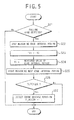
- Fig. 5 shows another example of the reverse rotation detection processing.
- the period between falling edges of the output signals from the comparison circuit 22 is measured as an edge interval period, whereupon a determination is made as to whether or not a ratio between a current value and a previous value of the edge interval period is equal to or greater than a threshold value C.
- the CPU 24 determines whether or not the falling edge of the output signal from the comparison circuit 22 has been detected in accordance with the output signal from the edge detection circuit 23 (step S21).
- the CPU 24 stops measuring the edge interval period (step S22), stores an edge interval period TC held at that point in time as a previous value TC1 (step S23), stores the edge interval period obtained anew through the measurement as the current edge interval period TC (step S24), and starts to measure the next edge interval period (step S25).
- This step is used to determine whether or not the crankshaft 10 has rotated in reverse during the measurement period of the current value TC of the edge interval period.
- TC/TC1 ⁇ C this indicates that the crankshaft 10 has rotated in reverse, and therefore the crank reverse rotation flag F_REVCRK is set to "1" (step S27).
- Fig. 6 shows an example of the crank angle signal waveform corresponding to reverse rotation positions Q1 to Q3 at which the rotor 11 starts to rotate in reverse.
- the rear end positions of the convex portions 12 and long convex portion 12a are disposed at fifteen degree intervals, the convex portions 12 have a width of five degrees, and the convex portion 12a has a width of ten degrees.
- the TDC position corresponds to the front end position of the convex portion 12 that is positioned adjacent to the rear end position side of the long convex portion 12a.
- the ratio TC/TC1 is calculated and compared with the threshold value C, but the ratio may be calculated as TC1/TC, whereupon a determination is made as to whether or not TC1/TC ⁇ C.
- F_REVCRK 1 is set in the step S27.
- the value of the threshold value C relating to TC1/TC is set at a different value to the threshold value C relating to TC/TC1.
- the convex portions 12 are formed on the rotor 11 as portions to be detected, but concave portions may be formed in the outer peripheral surface of the rotor 11 as the portions to be detected. Furthermore, instead of forming convex portions and concave portions on the outer peripheral surface of the rotor 11, the portions to be detected may be buried in the rotor 11 or formed as marks on the outer peripheral surface.
- the present invention is applied to a single-cylinder, four-cycle internal combustion engine, but the present invention may be applied to a multicylinder, four-cycle internal combustion engine or a two-cycle internal combustion engine.
- the portions to be detected are detected by the magnetic pickup 13, but the present invention is not limited thereto.
- the portions to be detected may be Hall elements or optical elements.
- the pickup 13 need only detect at least one of the front end position and rear end position of the portions to be detected.
- the difference between the detection time of the rear end position and the detection time of the next rear end position is detected as the edge interval period, but when the front ends of the convex portions 12 are formed at equal intervals, the difference between the detection time of the front end position and the detection time of the next front end position may be detected as the edge interval period to obtain TC/TC1.
Abstract
Description
- The present invention relates to a reverse rotation detection apparatus and a reverse rotation detection method for detecting rotation in the reverse direction of a crankshaft in an internal combustion engine.
- In an internal combustion engine, a crankshaft may rotate in reverse from a rotation direction which is previously given, namely from a state of rotation in the normal rotation direction under unstable combustion conditions such as engine start-up. In a conventional apparatus for detecting reverse rotation of a crankshaft, which is an abnormal operational state in an internal combustion engine, a plurality of teeth are formed at equal intervals on the outer periphery of an engine output shaft, two rotation speed sensors are provided for generating pulse signals having mutually different phases when the teeth pass therethrough, and a deviation signal between the signals obtained from the two rotation speed sensors is output as a sine wave signal via a filter and a comparator. The sine wave signal differs greatly between a normal rotation state and a reverse rotation state, and reverse rotation is determined from the difference (see
Japanese Unexamined Patent Application Publication H11-117780 - However, in the conventional reverse rotation detection apparatus, since the two rotation speed sensors are used, reverse rotation is first detected when the teeth pass through the two rotation speed sensors after the crankshaft has begun to rotate in reverse. Therefore, reverse rotation cannot be detected quickly.
- It is therefore an object of the present invention to provide a reverse rotation detection apparatus and a reverse rotation detection method with which reverse rotation of a crankshaft in an internal combustion engine can be detected quickly and precisely.
- A reverse rotation detection apparatus of the present invention comprises: a rotor having a plurality of portions to be detected which are arranged at equal angular intervals on an outer periphery thereof, for rotating in association with a crankshaft of an internal combustion engine; a pickup disposed near the outer periphery of the rotor, for detecting a front end position and a rear end position of each of the plurality of portions individually to generate a pulse signal; period detecting means for sequentially detecting a first period, which is an interval from a detected time of the front end position to a detected time of the rear end position, and a second period, which is an interval from the detection time of the rear end position to the detection time of the front end position, in accordance with the pulse signal output by the pickup; and reverse rotation determining means for comparing a first ratio between a current value and a previous value of the first period with a first threshold value, comparing a second ratio between a current value and a previous value of the second period with a second threshold value, and generating a reverse rotation detection signal in accordance with comparison results thereof.
- A reverse rotation detection method of the present invention is a method for detecting reverse rotation of a crankshaft in an internal combustion engine including a rotor having a plurality of portions to be detected which are arranged at equal angular intervals on an outer periphery thereof, for rotating in association with a crankshaft of an internal combustion engine, and a pickup disposed near the outer periphery of the rotor, for detecting a front end position and a rear end position of each of the plurality of portions individually to generate a pulse signal, the method comprising the steps of: sequentially detecting a first period, which is an interval from a detected time of the front end position to a detected time of the rear end position, and a second period, which is an interval from the detection time of the rear end position to the detection time of the front end position, in accordance with the pulse signal output by the pickup; and comparing a first ratio between a current value and a previous value of the first period with a first threshold value, comparing a second ratio between a current value and a previous value of the second period with a second threshold value, and generating a reverse rotation detection signal in accordance with comparison results thereof.
- According to the reverse rotation detection apparatus and reverse rotation detection method of the present invention, when reverse rotation occurs in the crankshaft, the first period or second period measured at the time point is extremely long, and therefore, by comparing the first ratio between the current value and previous value of the first period with the first threshold value and comparing the second ratio between the current value and previous value of the second period with the second threshold value, reverse rotation of the crankshaft can be detected quickly and precisely.
- Further, a reverse rotation detection apparatus of the present invention comprises: a rotor having a plurality of portions to be detected which are arranged at equal angular intervals on an outer periphery thereof, for rotating in association with a crankshaft of an internal combustion engine; a pickup disposed near the outer periphery of the rotor, for detecting at least one of a front end position and a rear end position of each of the plurality of portions to be detected to generate a pulse signal; period detecting means for sequentially detecting a period between detected times of either one of the front end position and the rear end position as an edge interval period in accordance with the pulse signal output by the pickup; and reverse rotation determining means for comparing a ratio between a current value and a previous value of the edge interval period with a third threshold value and generating a reverse rotation detection signal in accordance with a comparison result thereof.
- A reverse rotation detection method of the present invention is a method for detecting reverse rotation of a crankshaft in an internal combustion engine including a rotor having a plurality of portions to be detected which are arranged at equal angular intervals on an outer periphery thereof, for rotating in association with a crankshaft of an internal combustion engine, and a pickup disposed near the outer periphery of the rotor, for detecting at least one of a front end position and a rear end position of each of the plurality of portions to be detected to generate a pulse signal, the method comprising the steps of: sequentially detecting a period between detected times of either one of the front end position and the rear end position as an edge interval period in accordance with the pulse signal output by the pickup; and comparing a ratio between a current value and a previous value of the edge interval period with a third threshold value and generating a reverse rotation detection signal in accordance with a comparison result thereof.
- According to the reverse rotation detection apparatus and reverse rotation detection method of the present invention, when reverse rotation occurs in the crankshaft, the edge interval period measured at the time point is extremely long, and therefore, by comparing the ratio between the current value and previous value of the front end position edge interval period or rear end position edge interval period with the third threshold value, reverse rotation of the crankshaft can be detected quickly and precisely.
-
- Fig. 1 is a block diagram showing an embodiment of the present invention;
- Fig. 2 is a view showing the state of a signal waveform in each point of a reverse rotation detection apparatus shown in Fig. 1;
- Fig. 3 is a flowchart illustrating reverse rotation detection processing;
- Fig. 4 is a view showing an example of crank angle signal waveforms corresponding to reverse rotation positions P1 to P4 on a rotor;
- Fig. 5 is a flowchart illustrating other reverse rotation detection processing; and
- Fig. 6 is a view showing an example of crank angle signal waveforms corresponding to reverse rotation positions Q1 to Q3 on a rotor in the case of the reverse rotation detection processing shown in Fig. 5.
- An embodiment of the present invention will be described in detail below with reference to the drawings.
- Fig. 1 shows an engine control apparatus to which a reverse rotation detection apparatus according to the present invention is applied. The engine control apparatus comprises a crank
angle detection mechanism 1, an ECU (Electric Control Unit) 2, asensor group 3, and aninjector 4, and anignition apparatus 5. - The crank
angle detection mechanism 1 has a disk-shaped rotor 11 provided on acrankshaft 10 of a four-cycle internal combustion engine. Therotor 11 rotates in association with rotation of thecrankshaft 10. Twenty-fourconvex portions 12 made of a magnetic material are provided continuously at fifteen degree intervals on the outer peripheral surface of therotor 11 as portions to be detected. Amagnetic pickup 13 is disposed near the outer periphery of therotor 11. - When one of the
convex portions 12 passes by themagnetic pickup 13 by rotation of therotor 11, a pair of negative/positive pulses is generated by themagnetic pickup 13. The negative and positive pulses serve as a crank angle pulse signal. - The fifteen degree intervals of the twenty-four
convex portions 12 formed on the outer peripheral surface of therotor 11 relate to rear end positions of theconvex portions 12 in a normal rotation direction of the rotor 11 (the direction of an arrow RD). Oneconvex portion 12a of the twenty-fourconvex portions 12 indicates a reference angle of the crank angle. The reference angle corresponds to the rear end position of theconvex portion 12a in the rotation direction of therotor 11, or more specifically a position of -7 degrees from TDC, indicating the compression top dead center of a piston, within the 360 degrees of therotor 11. Further, theconvex portion 12a is formed to be longer than the other convex portions in the rotation direction of therotor 11. In other words, the length of theconvex portion 12a from the rear end position to a front end position is greater than that of the other convex portions, and therefore a time point at which the front end position of theconvex portion 12a is detected by themagnetic pickup 13 is earlier than a time point at which the front end position of each of the otherconvex portions 12 is detected. The length of thelong convex portion 12a from the front end position to the rear end position is at least twice the interval between the front end position of theconvex portion 12a and the rear end position of theadjacent convex portion 12, for example. Further, the length of theconvex portion 12a from the front end position to the rear end position is at least twice the length of each of the otherconvex portions 12 from the front end position to the rear end position, for example. - When the
rotor 11 rotates in the rotation direction, the rear end of theconvex portion 12 detected immediately after theconvex portion 12a is positioned within a range of 0 to 10 degrees from TDC. Further, a crank angle signal generated by themagnetic pickup 13 concerning thelong convex portion 12a serves as a reference pulse signal. - The ECU 2 is connected to an output of the
magnetic pickup 13. TheECU 2 comprises afilter circuit 21, acomparison circuit 22, anedge detection circuit 23, aCPU 24, aRAM 25, aROM 26,output interface circuits D converter 29. - The
filter circuit 21 has aresistor 21a andcapacitors magnetic pickup 13 to output the aforementioned negative/positive pulse pair. - The
comparison circuit 22 has acomparator 22a and areference voltage source 22b, and operates as a comparison circuit having a hysteresis function. Further, thecomparison circuit 22 switches from an high level output to an low level output when the output signal of thefilter circuit 21 increases to a predetermined voltage Vth, and switches from low level output to the high level output when the output signal of thefilter circuit 21 decreases to a predetermined voltage -Vth. A period of the high level output corresponds to a period of each of theconvex portions 12 of therotor 11, including theconvex portion 12a, and a period of the low level output corresponds to a period between twoconvex portions 12 which are adjacent to each other. The output signal of thecomparison circuit 22 is supplied to theCPU 24 as a crank angle signal. - The
edge detection circuit 23 detects a rising edge and a falling edge of the signal output by thecomparison circuit 22. - The
CPU 24 counts the low level period and the high level period individually in accordance with the edge detection performed by theedge detection circuit 23, and determines thelong convex portion 12a indicating the reference angle of the crank angle in distinction from the otherconvex portions 12 on the basis of the counting result. TheCPU 24 also performs ignition timing and fuel injection control in accordance with the determination result. - Further, the
CPU 24 detects reverse rotation of thecrankshaft 10 by repeatedly executing reverse rotation detection processing as described below. - The
CPU 24,RAM 25,ROM 26,output interface circuits D converter 29 are all connected to a common bus. - The
output interface circuit 27 drives theinjector 4 in accordance with an injector drive command from theCPU 24. Theinjector 4 is provided near an intake port of an intake pipe of the internal combustion engine, and injects fuel when driven. Theoutput interface circuit 28 activates theignition apparatus 5 in accordance with an electrification start command and an ignition start command from theCPU 24. More specifically, theoutput interface circuit 28 starts to electrify an ignition coil (not shown) of theignition apparatus 5 in accordance with the electrification start command, and causes a spark plug (not shown) to perform spark discharge by halting the electrification in accordance with the ignition start command. Theignition apparatus 5 is a full transistor type ignition apparatus, for example, which electrifies the ignition coil, generates a high voltage from an accumulated charge in the ignition coil, and applies the high voltage to the spark plug. - The A/
D converter 29 is provided for converting analog signals from thesensor group 3 for detecting engine operating parameters required in engine control, such as an intake pipe internal pressure PB, a cooling water temperature TW, a throttle opening θth, and an exhaust gas oxygen concentration O2, into digital signals. - In the engine control apparatus configured as described above, an output signal of the
magnetic pickup 13 passes through thefilter circuit 21 to form a substantially inverted triangle-shaped negative pulse relating to the front end of the convex portion 12 (including 12a) of therotor 11 and a substantially triangular positive pulse relating to the rear end, as shown in Fig. 2. When the output signal of thefilter circuit 21 decreases, it is compared with the predetermined voltage -Vth in thecomparison circuit 22, and when the output signal increases, it is compared with the predetermined voltage Vth. Thus, as shown in Fig. 2, the crank angle signal supplied to theedge detection circuit 23 from thecomparison circuit 22 is at a high level in relation to each of theconvex portions 12 of therotor 11 and at a low level in relation to each of the concave portions between theconvex portions 12. - The
edge detection circuit 23 detects the rising edge and falling edge of the crank angle signal, and supplies theCPU 24 with signals indicating the respective detection times. TheCPU 24 measures the period between the rising edge and falling edge detected by theedge detection circuit 23. The rising edge corresponds to the front end of theconvex portion 12, and the falling edge corresponds to the rear end of theconvex portion 12. The period from the rising edge to the falling edge corresponding to theconvex portion 12 of therotor 11 is detected as a convex portion period TCPRJ (first period). The period from the falling edge to the rising edge corresponding to the concave portion between theconvex portions 12 of therotor 11 is detected as a concave portion period TCDENT (second period). In Fig. 2, TCPRJ denotes a current value of the convex portion period, TCPRJ1 denotes a previous value of the convex portion period, TCDENT denotes a current value of the concave portion period, and TCDENT1 denotes a previous value of the concave portion period, using a time point T as a reference. - As shown in Fig. 3, in the reverse rotation detection processing, the
CPU 24 first determines whether or not a rising edge of the output signal from thecomparison circuit 22 has been detected in accordance with the output signal of the edge detection circuit 23 (step S1). When the rising edge has been detected, theCPU 24 stops measuring the concave portion period (step S2), stores the concave portion period TCDENT held at the current time point as the previous value TCDENT1 (step S3), stores the concave portion period newly obtained through the measurement as the current concave portion period TCDENT (step S4), and starts to measure a convex portion period (step S5). - On the other hand, when the rising edge has not been detected, a determination is made as to whether or not a falling edge of the output signal from the
comparison circuit 22 has been detected (step S6). When the falling edge has been detected, theCPU 24 stops measuring the convex portion period (step S7), stores the convex portion period TCPRJ held at the current time point as the previous value TCPRJ1 (step S8), stores the convex portion period newly obtained through the measurement as the current convex portion period TCPRJ (step S9), and starts to measure a concave portion period (step S10). - After executing the step S10, the
CPU 24 determines whether or not a ratio (second ratio) = TCDENT/TCDENT1 between the current value TCDENT and the previous value TCDENT1 of the concave portion period, obtained in the steps S4 and S3, is equal to or greater than a threshold value A (second threshold value) (step S11). This step is used to determine whether or not thecrankshaft 10 has rotated in reverse during the measurement period of the current value TCDENT of the concave portion period. When TCDENT/TCDENT1 ≥ A, this indicates that thecrankshaft 10 has rotated in reverse, and therefore a crank reverse rotation flag F_REVCRK is set to "1" (step S12). On the other hand, when TCDENT/TCDENT1 < A, a determination is made as to whether or not a ratio (first ratio) = TCPRJ/TCPRJ1 between the current value TCPRJ and the previous value TCPRJ1 of the convex portion period, obtained in the steps S9 and S8, is equal to or greater than a threshold value B (first threshold value) (step S13). This step is used to determine whether or not thecrankshaft 10 has rotated in reverse during the measurement period of the current value TCPRJ of the convex portion period. When TCPRJ/TCPRJ1 ≥ B, this indicates that thecrankshaft 10 has rotated in reverse, and therefore the routine advances to the step S12, where the crank reverse rotation flag F_REVCRK is set to "1." F_REVCRK = 1 corresponds to a reverse rotation detection signal. The crank reverse rotation flag F_REVCRK is reset to "0" immediately before starting the engine. - Fig. 4 shows an example of a waveform of the crank angle signal (the output signal of the comparison circuit 22) corresponding to reverse rotation positions P1 to P4 at which the
rotor 11 starts to rotate in reverse. In the normal rotation direction of therotor 11, the rear end positions of theconvex portions 12 and longconvex portion 12a are disposed at fifteen degree intervals, theconvex portions 12 each have a width of five degrees, and theconvex portion 12a has a width of ten degrees. Furthermore, in therotor 11, the TDC position corresponds to the front end position of aconvex portion 12 that is positioned adjacent to the rear end position side of the longconvex portion 12a. - In the case where the reverse rotation position is P1 or P3, TCDENT/TCDENT1 ≥ A is satisfied. In the case where the reverse rotation position is P2 or P4, TCPRJ/TCPRJ1 ≥ B is satisfied. When the
crankshaft 10 starts to rotate in reverse, the rotation speed (angular velocity) of therotor 11 decreases gradually in the normal rotation direction until it reaches zero, and then increases gradually in the reverse rotation direction. As a result, the periods of TCDENT and TCPRJ become longer than the periods of TCDENT1 and TCPRJ1, respectively. - When the
CPU 24 detects reverse rotation of thecrankshaft 10 in the reverse rotation detection processing such that F_REVCRK = 1, ignition of theignition apparatus 5 and fuel injection through theinjector 4 are stopped. - In the reverse rotation detection processing of Fig. 3, when reverse rotation of the
crankshaft 10 occurs, the convex portion period or concave portion period measured at the time point becomes extremely long, and therefore, by determining whether or not the ratio = TCDENT/TCDENT1 between the current value TCDENT and the previous value TCDENT1 of the concave portion period is equal to or greater than the threshold value A or whether or not the ratio = TCPRJ/TCPRJ1 between the current value TCPRJ and the previous value TCPRJ1 of the convex portion period is equal to or greater than the threshold value B, reverse rotation of thecrankshaft 10 can be detected quickly and precisely. - In the step S11, the ratio TCDENT/TCDENT1 is calculated and compared with the threshold value A, but the ratio may be calculated as TCDENT1/TCDENT, whereupon a determination is made as to whether or not TCDENT1/TCDENT ≤ A. Similarly, in the step S13, the ratio TCPRJ/TCPRJ1 is calculated and compared with the threshold value B, but the ratio may be calculated as TCPRJ1/TCDPRJ, whereupon a determination is made as to whether or not TCPRJ1/TCPRJ ≤ B. When TCDENT1/TCDENT ≤ A or TCPRJ1/TCPRJ ≤ B is satisfied, F_REVCRK = 1 is set in the step S12. Further, the values of the threshold values A, B relating to TCDENT1/TCDENT and TCPRJ1/TCPRJ respectively are set at different values to the threshold values A, B relating to TCDENT/TCDENT1 and TCPRJ/TCPRJ1 respectively.
- Fig. 5 shows another example of the reverse rotation detection processing. In the reverse rotation detection processing of Fig. 5, the period between falling edges of the output signals from the
comparison circuit 22 is measured as an edge interval period, whereupon a determination is made as to whether or not a ratio between a current value and a previous value of the edge interval period is equal to or greater than a threshold value C. - More specifically, first the
CPU 24 determines whether or not the falling edge of the output signal from thecomparison circuit 22 has been detected in accordance with the output signal from the edge detection circuit 23 (step S21). When the falling edge has been detected, theCPU 24 stops measuring the edge interval period (step S22), stores an edge interval period TC held at that point in time as a previous value TC1 (step S23), stores the edge interval period obtained anew through the measurement as the current edge interval period TC (step S24), and starts to measure the next edge interval period (step S25). - After executing the step S25, the
CPU 24 determines whether or not a ratio = TC/TC1 between the current value TC and the previous value TC1 of the edge interval period, obtained in the steps S24 and S23, is equal to or greater than the threshold value C (third threshold value) (step S26). This step is used to determine whether or not thecrankshaft 10 has rotated in reverse during the measurement period of the current value TC of the edge interval period. When TC/TC1 ≥ C, this indicates that thecrankshaft 10 has rotated in reverse, and therefore the crank reverse rotation flag F_REVCRK is set to "1" (step S27). - Fig. 6 shows an example of the crank angle signal waveform corresponding to reverse rotation positions Q1 to Q3 at which the
rotor 11 starts to rotate in reverse. In the normal rotation direction of therotor 11, the rear end positions of theconvex portions 12 and longconvex portion 12a are disposed at fifteen degree intervals, theconvex portions 12 have a width of five degrees, and theconvex portion 12a has a width of ten degrees. Furthermore, in therotor 11, the TDC position corresponds to the front end position of theconvex portion 12 that is positioned adjacent to the rear end position side of the longconvex portion 12a. - In the case of each of the reverse rotation positions Q1 to Q3, TC/TC1 ≥ C in the reverse rotation detection processing of Fig. 5 is satisfied. When the
crankshaft 10 rotates in reverse, the rotation speed (angular velocity) of therotor 11 decreases gradually in the normal rotation direction until it reaches zero, and then increases gradually in the reverse rotation direction. As a result, the period of TC becomes longer than the period of TC1. - Thus, in the reverse rotation detection processing of Fig. 5, when reverse rotation of the
crankshaft 10 occurs, the edge interval period measured at the time point becomes extremely long, and therefore, by determining whether or not the ratio = TC/TC1 between the current value TC and the previous value TC1 of the edge interval period is equal to or greater than the threshold value C, reverse rotation of thecrankshaft 10 can be detected quickly and precisely. - In the step S26, the ratio TC/TC1 is calculated and compared with the threshold value C, but the ratio may be calculated as TC1/TC, whereupon a determination is made as to whether or not TC1/TC ≤ C. When TC1/TC ≤ C is satisfied, F_REVCRK = 1 is set in the step S27. The value of the threshold value C relating to TC1/TC is set at a different value to the threshold value C relating to TC/TC1.
- In the embodiment described above, the
convex portions 12 are formed on therotor 11 as portions to be detected, but concave portions may be formed in the outer peripheral surface of therotor 11 as the portions to be detected. Furthermore, instead of forming convex portions and concave portions on the outer peripheral surface of therotor 11, the portions to be detected may be buried in therotor 11 or formed as marks on the outer peripheral surface. - Further, in the above embodiment, the present invention is applied to a single-cylinder, four-cycle internal combustion engine, but the present invention may be applied to a multicylinder, four-cycle internal combustion engine or a two-cycle internal combustion engine.
- Furthermore, in the embodiment described above, the portions to be detected are detected by the
magnetic pickup 13, but the present invention is not limited thereto. The portions to be detected may be Hall elements or optical elements. Moreover, in the reverse rotation detection processing of Fig. 5, thepickup 13 need only detect at least one of the front end position and rear end position of the portions to be detected. - Further, in the embodiment described above, reverse rotation of the
crankshaft 10 is detected, but an unstable rotation state in which reverse rotation may occur following ignition may also be detected. - Furthermore, in the reverse rotation detection processing of Fig. 5, the difference between the detection time of the rear end position and the detection time of the next rear end position is detected as the edge interval period, but when the front ends of the
convex portions 12 are formed at equal intervals, the difference between the detection time of the front end position and the detection time of the next front end position may be detected as the edge interval period to obtain TC/TC1.
Claims (9)
- A reverse rotation detection apparatus comprising:a rotor having a plurality of portions to be detected which are arranged at equal angular intervals on an outer periphery thereof, for rotating in association with a crankshaft of an internal combustion engine;a pickup disposed near said outer periphery of said rotor, for detecting a front end position and a rear end position of each of said plurality of portions individually to generate a pulse signal;period detecting means for sequentially detecting a first period, which is an interval from a detected time of the front end position to a detected time of the rear end position, and a second period, which is an interval from the detection time of the rear end position to the detection time of the front end position, in accordance with said pulse signal output by said pickup; andreverse rotation determining means for comparing a first ratio between a current value and a previous value of the first period with a first threshold value, comparing a second ratio between a current value and a previous value of the second period with a second threshold value, and generating a reverse rotation detection signal in accordance with comparison results thereof.
- The reverse rotation detection apparatus according to claim 1, wherein said reverse rotation determining means generate the reverse rotation detection signal when the first ratio = the current value of the first period/the previous value of the first period is equal to or greater than the first threshold value or when the second ratio = the current value of the second period/the previous value of the second period is equal to or greater than the second threshold value.
- The reverse rotation detection apparatus according to claim 1, wherein each of said plurality of portions to be detected is constituted by a convex portion, and one portion of said plurality of portions to be detected is different in length from the other portions in a rotation direction of said rotor in order to detect a reference angle of a crank angle.
- The reverse rotation detection apparatus according to claim 3, wherein the rear end positions of said plurality of portions to be detected are arranged respectively at equal angular intervals in a rotation direction of said rotor, and a length from the rear end position to the front end position of the one portion for detecting the reference angle is greater than a length from the rear end position to the front end position of each of the other detected portions.
- The reverse rotation detection apparatus according to claim 1, wherein said pickup is a magnetic pickup for magnetically detecting each of said plurality of portions to be detected, which are disposed near the outer periphery of said rotor and each constituted by a magnetic material.
- A reverse rotation detection apparatus comprising:a rotor having a plurality of portions to be detected which are arranged at equal angular intervals on an outer periphery thereof, for rotating in association with a crankshaft of an internal combustion engine;a pickup disposed near the outer periphery of said rotor, for detecting at least one of a front end position and a rear end position of each of said plurality of portions to be detected to generate a pulse signal;period detecting means for sequentially detecting a period between detected times of either one of the front end position and the rear end position as an edge interval period in accordance with the pulse signal output by said pickup; andreverse rotation determining means for comparing a ratio between a current value and a previous value of the edge interval period with a third threshold value and generating a reverse rotation detection signal in accordance with a comparison result thereof.
- The reverse rotation detection apparatus according to claim 6, wherein said reverse rotation determining means generate the reverse rotation detection signal when the ratio = the current value of the edge interval period/the previous value of the edge interval period is equal to or greater than the third threshold value.
- A reverse rotation detection method for detecting reverse rotation of a crankshaft in an internal combustion engine including a rotor having a plurality of portions to be detected which are arranged at equal angular intervals on an outer periphery thereof, for rotating in association with a crankshaft of an internal combustion engine, and a pickup disposed near said outer periphery of said rotor, for detecting a front end position and a rear end position of each of said plurality of portions individually to generate a pulse signal, said method comprising the steps of:sequentially detecting a first period, which is an interval from a detected time of the front end position to a detected time of the rear end position, and a second period, which is an interval from the detection time of the rear end position to the detection time of the front end position, in accordance with said pulse signal output by said pickup; andcomparing a first ratio between a current value and a previous value of the first period with a first threshold value, comparing a second ratio between a current value and a previous value of the second period with a second threshold value, and generating a reverse rotation detection signal in accordance with comparison results thereof.
- A reverse rotation detection method for detecting reverse rotation of a crankshaft in an internal combustion engine including a rotor having a plurality of portions to be detected which are arranged at equal angular intervals on an outer periphery thereof, for rotating in association with a crankshaft of an internal combustion engine, and a pickup disposed near the outer periphery of said rotor, for detecting at least one of a front end position and a rear end position of each of said plurality of portions to be detected to generate a pulse signal, said method comprising the steps of:sequentially detecting a period between detected times of either one of the front end position and the rear end position as an edge interval period in accordance with the pulse signal output by said pickup; andcomparing a ratio between a current value and a previous value of the edge interval period with a third threshold value and generating a reverse rotation detection signal in accordance with a comparison result thereof.
Applications Claiming Priority (1)
| Application Number | Priority Date | Filing Date | Title |
|---|---|---|---|
| JP2006189016A JP4754424B2 (en) | 2006-07-10 | 2006-07-10 | Internal combustion engine reverse rotation detection device and reverse rotation detection method |
Publications (3)
| Publication Number | Publication Date |
|---|---|
| EP1878897A2 true EP1878897A2 (en) | 2008-01-16 |
| EP1878897A3 EP1878897A3 (en) | 2012-10-10 |
| EP1878897B1 EP1878897B1 (en) | 2014-08-20 |
Family
ID=38571908
Family Applications (1)
| Application Number | Title | Priority Date | Filing Date |
|---|---|---|---|
| EP07111227.0A Expired - Fee Related EP1878897B1 (en) | 2006-07-10 | 2007-06-28 | Reverse rotation detection apparatus and reverse rotation detection method for internal combustion engine |
Country Status (2)
| Country | Link |
|---|---|
| EP (1) | EP1878897B1 (en) |
| JP (1) | JP4754424B2 (en) |
Cited By (5)
| Publication number | Priority date | Publication date | Assignee | Title |
|---|---|---|---|---|
| FR2942851A1 (en) * | 2009-03-04 | 2010-09-10 | Peugeot Citroen Automobiles Sa | METHOD FOR ESTIMATING THE STOP POSITION OF A COMBUSTION ENGINE |
| WO2016148787A1 (en) | 2015-03-18 | 2016-09-22 | Exxonmobil Upstream Research Company | Single sensor systems and methods for detection of reverse rotation |
| WO2016165829A1 (en) * | 2015-04-16 | 2016-10-20 | Continental Automotive France | Method and device for detecting reverse rotation of an internal combustion engine |
| CN106948957A (en) * | 2015-12-16 | 2017-07-14 | 现代自动车株式会社 | The counter-rotational method of vehicle motor is sensed using the tooth period ratio of bent axle |
| WO2020065020A1 (en) * | 2018-09-27 | 2020-04-02 | Continental Automotive France | Reverse-rotation robust synchronization method |
Families Citing this family (4)
| Publication number | Priority date | Publication date | Assignee | Title |
|---|---|---|---|---|
| JP5148530B2 (en) * | 2009-02-20 | 2013-02-20 | 株式会社ケーヒン | Ignition control device for internal combustion engine |
| US8327825B2 (en) | 2009-02-20 | 2012-12-11 | Keihin Corporation | Control apparatus for internal combustion engine |
| JP5381747B2 (en) * | 2010-01-26 | 2014-01-08 | 株式会社デンソー | Fuel injection device |
| JP6393564B2 (en) * | 2014-09-11 | 2018-09-19 | 株式会社ケーヒン | Fuel injection control device |
Citations (4)
| Publication number | Priority date | Publication date | Assignee | Title |
|---|---|---|---|---|
| US6058909A (en) * | 1998-06-15 | 2000-05-09 | Mitsubishi Denki Kabushiki Kaisha | Cylinder identifying apparatus for an internal-combustion engine |
| DE10320367A1 (en) * | 2002-05-08 | 2003-11-27 | Denso Corp | Ignition control device for an internal combustion engine |
| EP1384878A1 (en) * | 2002-07-22 | 2004-01-28 | Hitachi Unisia Automotive Ltd. | Control apparatus and control method of engine |
| US6786212B1 (en) * | 2003-10-22 | 2004-09-07 | Hyundai Motor Company | Method for preventing a reverse rotation of an engine |
Family Cites Families (4)
| Publication number | Priority date | Publication date | Assignee | Title |
|---|---|---|---|---|
| JP3375679B2 (en) * | 1993-05-24 | 2003-02-10 | 本田技研工業株式会社 | Reverse rotation prevention device for internal combustion engine |
| JP2005042589A (en) * | 2003-07-25 | 2005-02-17 | Toyota Motor Corp | Crank angle detector of internal combustion engine |
| JP4014580B2 (en) * | 2004-04-02 | 2007-11-28 | 株式会社ケーヒン | Ignition timing control device for internal combustion engine |
| JP2006046236A (en) * | 2004-08-06 | 2006-02-16 | Kokusan Denki Co Ltd | Method and device for determining rotation direction of internal combustion engine |
-
2006
- 2006-07-10 JP JP2006189016A patent/JP4754424B2/en not_active Expired - Fee Related
-
2007
- 2007-06-28 EP EP07111227.0A patent/EP1878897B1/en not_active Expired - Fee Related
Patent Citations (4)
| Publication number | Priority date | Publication date | Assignee | Title |
|---|---|---|---|---|
| US6058909A (en) * | 1998-06-15 | 2000-05-09 | Mitsubishi Denki Kabushiki Kaisha | Cylinder identifying apparatus for an internal-combustion engine |
| DE10320367A1 (en) * | 2002-05-08 | 2003-11-27 | Denso Corp | Ignition control device for an internal combustion engine |
| EP1384878A1 (en) * | 2002-07-22 | 2004-01-28 | Hitachi Unisia Automotive Ltd. | Control apparatus and control method of engine |
| US6786212B1 (en) * | 2003-10-22 | 2004-09-07 | Hyundai Motor Company | Method for preventing a reverse rotation of an engine |
Cited By (14)
| Publication number | Priority date | Publication date | Assignee | Title |
|---|---|---|---|---|
| FR2942851A1 (en) * | 2009-03-04 | 2010-09-10 | Peugeot Citroen Automobiles Sa | METHOD FOR ESTIMATING THE STOP POSITION OF A COMBUSTION ENGINE |
| WO2010100357A1 (en) * | 2009-03-04 | 2010-09-10 | Peugeot Citroën Automobiles SA | Method for estimating the stoppage position of a combustion engine |
| WO2016148787A1 (en) | 2015-03-18 | 2016-09-22 | Exxonmobil Upstream Research Company | Single sensor systems and methods for detection of reverse rotation |
| US10393767B2 (en) | 2015-03-18 | 2019-08-27 | Exxonmobil Upstream Research Company | Single sensor systems and methods for detection of reverse rotation |
| KR20170139568A (en) * | 2015-04-16 | 2017-12-19 | 콘티넨탈 오토모티브 프랑스 | Method and apparatus for detecting reverse rotation of an internal combustion engine |
| FR3035157A1 (en) * | 2015-04-16 | 2016-10-21 | Continental Automotive France | METHOD AND DEVICE FOR DETECTION OF REVERSE ROTATION OF AN INTERNAL COMBUSTION ENGINE |
| CN107532529A (en) * | 2015-04-16 | 2018-01-02 | 法国大陆汽车公司 | For the method and apparatus for the reverse rotation for detecting explosive motor |
| WO2016165829A1 (en) * | 2015-04-16 | 2016-10-20 | Continental Automotive France | Method and device for detecting reverse rotation of an internal combustion engine |
| CN107532529B (en) * | 2015-04-16 | 2019-11-26 | 法国大陆汽车公司 | Method and apparatus for detecting the reverse rotation of internal combustion engine |
| CN106948957A (en) * | 2015-12-16 | 2017-07-14 | 现代自动车株式会社 | The counter-rotational method of vehicle motor is sensed using the tooth period ratio of bent axle |
| CN106948957B (en) * | 2015-12-16 | 2021-06-01 | 现代自动车株式会社 | Method for sensing reverse rotation of vehicle engine using tooth period ratio of crankshaft |
| WO2020065020A1 (en) * | 2018-09-27 | 2020-04-02 | Continental Automotive France | Reverse-rotation robust synchronization method |
| FR3086695A1 (en) * | 2018-09-27 | 2020-04-03 | Continental Automotive France | ROBUST REVERSE ROTATION SYNCHRONIZATION PROCESS |
| US11313298B2 (en) | 2018-09-27 | 2022-04-26 | Vitesco Technologies GmbH | Reverse-rotation robust synchronization method |
Also Published As
| Publication number | Publication date |
|---|---|
| EP1878897B1 (en) | 2014-08-20 |
| JP2008014287A (en) | 2008-01-24 |
| JP4754424B2 (en) | 2011-08-24 |
| EP1878897A3 (en) | 2012-10-10 |
Similar Documents
| Publication | Publication Date | Title |
|---|---|---|
| EP1878897B1 (en) | Reverse rotation detection apparatus and reverse rotation detection method for internal combustion engine | |
| US4562818A (en) | Method and apparatus for controlling the air-fuel ratio in an internal combustion engine | |
| US20080087249A1 (en) | Crank Angle Detector Of Internal Combustion Engine And Ignition Timing Controller | |
| US7360407B2 (en) | Crank angle detecting apparatus and reference angular position detection method for internal combustion engine | |
| WO2007139042A1 (en) | Internal combustion engine knocking judgment device and knocking judgment method | |
| JP2807737B2 (en) | Device for detecting combustion state of internal combustion engine | |
| JPWO2004013479A1 (en) | Engine control device | |
| JP3126689B2 (en) | Engine control device | |
| JP2007040208A (en) | Controller for internal combustion engine | |
| CN100516489C (en) | Device for determining stroke of engine | |
| US6411917B1 (en) | Engine speed calculating apparatus | |
| US6837100B1 (en) | Detection of combustion misfiring | |
| US6058766A (en) | Crank angle detector | |
| KR0151519B1 (en) | Rpm detection device of an internal combustion engine | |
| JP2009235963A (en) | Method and device for detecting crank angle of engine | |
| JP2005042589A (en) | Crank angle detector of internal combustion engine | |
| JP2007047128A (en) | Rotation angle sensitive device of rotating body | |
| JPH02233837A (en) | Reverse preventer for internal combustion engine | |
| RU2170915C1 (en) | Mwthod of determination of phase of internal combustion engine working cycle | |
| RU2242734C2 (en) | Method to determine phase of working cycle of internal combustion engine | |
| JP2005240606A (en) | Crank angle determining device for internal combustion engine | |
| JP2631851B2 (en) | Ignition timing control device | |
| JP2000045849A (en) | Complete explosion detecting device for internal combustion | |
| JP2005023808A (en) | Rotation state detecting device for crankshaft | |
| JPH09303188A (en) | Control device for engine |
Legal Events
| Date | Code | Title | Description |
|---|---|---|---|
| PUAI | Public reference made under article 153(3) epc to a published international application that has entered the european phase |
Free format text: ORIGINAL CODE: 0009012 |
|
| AK | Designated contracting states |
Kind code of ref document: A2 Designated state(s): AT BE BG CH CY CZ DE DK EE ES FI FR GB GR HU IE IS IT LI LT LU LV MC MT NL PL PT RO SE SI SK TR |
|
| AX | Request for extension of the european patent |
Extension state: AL BA HR MK YU |
|
| 17P | Request for examination filed |
Effective date: 20080303 |
|
| PUAL | Search report despatched |
Free format text: ORIGINAL CODE: 0009013 |
|
| AK | Designated contracting states |
Kind code of ref document: A3 Designated state(s): AT BE BG CH CY CZ DE DK EE ES FI FR GB GR HU IE IS IT LI LT LU LV MC MT NL PL PT RO SE SI SK TR |
|
| AX | Request for extension of the european patent |
Extension state: AL BA HR MK RS |
|
| RIC1 | Information provided on ipc code assigned before grant |
Ipc: F02D 41/06 20060101AFI20120831BHEP |
|
| AKX | Designation fees paid |
Designated state(s): DE FR GB |
|
| GRAP | Despatch of communication of intention to grant a patent |
Free format text: ORIGINAL CODE: EPIDOSNIGR1 |
|
| INTG | Intention to grant announced |
Effective date: 20140320 |
|
| GRAS | Grant fee paid |
Free format text: ORIGINAL CODE: EPIDOSNIGR3 |
|
| GRAA | (expected) grant |
Free format text: ORIGINAL CODE: 0009210 |
|
| RIN1 | Information on inventor provided before grant (corrected) |
Inventor name: TOKUGAWA, KAZUHITO Inventor name: WATANABE, KUNITOSHI Inventor name: ISHIKAWA, SHINICHI |
|
| AK | Designated contracting states |
Kind code of ref document: B1 Designated state(s): DE FR GB |
|
| REG | Reference to a national code |
Ref country code: GB Ref legal event code: FG4D |
|
| REG | Reference to a national code |
Ref country code: DE Ref legal event code: R096 Ref document number: 602007038185 Country of ref document: DE Effective date: 20140925 |
|
| REG | Reference to a national code |
Ref country code: DE Ref legal event code: R097 Ref document number: 602007038185 Country of ref document: DE |
|
| REG | Reference to a national code |
Ref country code: FR Ref legal event code: PLFP Year of fee payment: 9 |
|
| REG | Reference to a national code |
Ref country code: DE Ref legal event code: R082 Ref document number: 602007038185 Country of ref document: DE Representative=s name: STAUDT IP LAW, DE |
|
| PLBE | No opposition filed within time limit |
Free format text: ORIGINAL CODE: 0009261 |
|
| STAA | Information on the status of an ep patent application or granted ep patent |
Free format text: STATUS: NO OPPOSITION FILED WITHIN TIME LIMIT |
|
| 26N | No opposition filed |
Effective date: 20150521 |
|
| REG | Reference to a national code |
Ref country code: FR Ref legal event code: PLFP Year of fee payment: 10 |
|
| REG | Reference to a national code |
Ref country code: FR Ref legal event code: PLFP Year of fee payment: 11 |
|
| REG | Reference to a national code |
Ref country code: FR Ref legal event code: PLFP Year of fee payment: 12 |
|
| PGFP | Annual fee paid to national office [announced via postgrant information from national office to epo] |
Ref country code: DE Payment date: 20200617 Year of fee payment: 14 Ref country code: FR Payment date: 20200512 Year of fee payment: 14 |
|
| PGFP | Annual fee paid to national office [announced via postgrant information from national office to epo] |
Ref country code: GB Payment date: 20200618 Year of fee payment: 14 |
|
| REG | Reference to a national code |
Ref country code: DE Ref legal event code: R119 Ref document number: 602007038185 Country of ref document: DE |
|
| GBPC | Gb: european patent ceased through non-payment of renewal fee |
Effective date: 20210628 |
|
| PG25 | Lapsed in a contracting state [announced via postgrant information from national office to epo] |
Ref country code: GB Free format text: LAPSE BECAUSE OF NON-PAYMENT OF DUE FEES Effective date: 20210628 Ref country code: DE Free format text: LAPSE BECAUSE OF NON-PAYMENT OF DUE FEES Effective date: 20220101 |
|
| PG25 | Lapsed in a contracting state [announced via postgrant information from national office to epo] |
Ref country code: FR Free format text: LAPSE BECAUSE OF NON-PAYMENT OF DUE FEES Effective date: 20210630 |