EP1878895A2 - Control of supercharged engine - Google Patents
Control of supercharged engine Download PDFInfo
- Publication number
- EP1878895A2 EP1878895A2 EP07013800A EP07013800A EP1878895A2 EP 1878895 A2 EP1878895 A2 EP 1878895A2 EP 07013800 A EP07013800 A EP 07013800A EP 07013800 A EP07013800 A EP 07013800A EP 1878895 A2 EP1878895 A2 EP 1878895A2
- Authority
- EP
- European Patent Office
- Prior art keywords
- exhaust
- motor
- state
- engine
- internal combustion
- Prior art date
- Legal status (The legal status is an assumption and is not a legal conclusion. Google has not performed a legal analysis and makes no representation as to the accuracy of the status listed.)
- Granted
Links
Images





Classifications
-
- F—MECHANICAL ENGINEERING; LIGHTING; HEATING; WEAPONS; BLASTING
- F02—COMBUSTION ENGINES; HOT-GAS OR COMBUSTION-PRODUCT ENGINE PLANTS
- F02D—CONTROLLING COMBUSTION ENGINES
- F02D41/00—Electrical control of supply of combustible mixture or its constituents
- F02D41/0002—Controlling intake air
- F02D41/0007—Controlling intake air for control of turbo-charged or super-charged engines
-
- F—MECHANICAL ENGINEERING; LIGHTING; HEATING; WEAPONS; BLASTING
- F02—COMBUSTION ENGINES; HOT-GAS OR COMBUSTION-PRODUCT ENGINE PLANTS
- F02B—INTERNAL-COMBUSTION PISTON ENGINES; COMBUSTION ENGINES IN GENERAL
- F02B37/00—Engines characterised by provision of pumps driven at least for part of the time by exhaust
- F02B37/02—Gas passages between engine outlet and pump drive, e.g. reservoirs
- F02B37/025—Multiple scrolls or multiple gas passages guiding the gas to the pump drive
-
- F—MECHANICAL ENGINEERING; LIGHTING; HEATING; WEAPONS; BLASTING
- F02—COMBUSTION ENGINES; HOT-GAS OR COMBUSTION-PRODUCT ENGINE PLANTS
- F02D—CONTROLLING COMBUSTION ENGINES
- F02D13/00—Controlling the engine output power by varying inlet or exhaust valve operating characteristics, e.g. timing
- F02D13/02—Controlling the engine output power by varying inlet or exhaust valve operating characteristics, e.g. timing during engine operation
- F02D13/0242—Variable control of the exhaust valves only
- F02D13/0249—Variable control of the exhaust valves only changing the valve timing only
-
- F—MECHANICAL ENGINEERING; LIGHTING; HEATING; WEAPONS; BLASTING
- F02—COMBUSTION ENGINES; HOT-GAS OR COMBUSTION-PRODUCT ENGINE PLANTS
- F02D—CONTROLLING COMBUSTION ENGINES
- F02D23/00—Controlling engines characterised by their being supercharged
-
- F—MECHANICAL ENGINEERING; LIGHTING; HEATING; WEAPONS; BLASTING
- F01—MACHINES OR ENGINES IN GENERAL; ENGINE PLANTS IN GENERAL; STEAM ENGINES
- F01N—GAS-FLOW SILENCERS OR EXHAUST APPARATUS FOR MACHINES OR ENGINES IN GENERAL; GAS-FLOW SILENCERS OR EXHAUST APPARATUS FOR INTERNAL-COMBUSTION ENGINES
- F01N13/00—Exhaust or silencing apparatus characterised by constructional features
- F01N13/08—Other arrangements or adaptations of exhaust conduits
- F01N13/10—Other arrangements or adaptations of exhaust conduits of exhaust manifolds
- F01N13/107—More than one exhaust manifold or exhaust collector
-
- F—MECHANICAL ENGINEERING; LIGHTING; HEATING; WEAPONS; BLASTING
- F02—COMBUSTION ENGINES; HOT-GAS OR COMBUSTION-PRODUCT ENGINE PLANTS
- F02B—INTERNAL-COMBUSTION PISTON ENGINES; COMBUSTION ENGINES IN GENERAL
- F02B37/00—Engines characterised by provision of pumps driven at least for part of the time by exhaust
- F02B37/12—Control of the pumps
- F02B37/18—Control of the pumps by bypassing exhaust from the inlet to the outlet of turbine or to the atmosphere
-
- F—MECHANICAL ENGINEERING; LIGHTING; HEATING; WEAPONS; BLASTING
- F02—COMBUSTION ENGINES; HOT-GAS OR COMBUSTION-PRODUCT ENGINE PLANTS
- F02B—INTERNAL-COMBUSTION PISTON ENGINES; COMBUSTION ENGINES IN GENERAL
- F02B37/00—Engines characterised by provision of pumps driven at least for part of the time by exhaust
- F02B37/12—Control of the pumps
- F02B37/24—Control of the pumps by using pumps or turbines with adjustable guide vanes
-
- F—MECHANICAL ENGINEERING; LIGHTING; HEATING; WEAPONS; BLASTING
- F02—COMBUSTION ENGINES; HOT-GAS OR COMBUSTION-PRODUCT ENGINE PLANTS
- F02D—CONTROLLING COMBUSTION ENGINES
- F02D13/00—Controlling the engine output power by varying inlet or exhaust valve operating characteristics, e.g. timing
- F02D13/02—Controlling the engine output power by varying inlet or exhaust valve operating characteristics, e.g. timing during engine operation
- F02D13/0261—Controlling the valve overlap
-
- F—MECHANICAL ENGINEERING; LIGHTING; HEATING; WEAPONS; BLASTING
- F02—COMBUSTION ENGINES; HOT-GAS OR COMBUSTION-PRODUCT ENGINE PLANTS
- F02D—CONTROLLING COMBUSTION ENGINES
- F02D41/00—Electrical control of supply of combustible mixture or its constituents
- F02D41/0002—Controlling intake air
- F02D2041/001—Controlling intake air for engines with variable valve actuation
-
- Y—GENERAL TAGGING OF NEW TECHNOLOGICAL DEVELOPMENTS; GENERAL TAGGING OF CROSS-SECTIONAL TECHNOLOGIES SPANNING OVER SEVERAL SECTIONS OF THE IPC; TECHNICAL SUBJECTS COVERED BY FORMER USPC CROSS-REFERENCE ART COLLECTIONS [XRACs] AND DIGESTS
- Y02—TECHNOLOGIES OR APPLICATIONS FOR MITIGATION OR ADAPTATION AGAINST CLIMATE CHANGE
- Y02T—CLIMATE CHANGE MITIGATION TECHNOLOGIES RELATED TO TRANSPORTATION
- Y02T10/00—Road transport of goods or passengers
- Y02T10/10—Internal combustion engine [ICE] based vehicles
- Y02T10/12—Improving ICE efficiencies
Definitions
- the present description generally relates to a supercharged engine, and more particularly relates to control a supercharging system, having a motor and an exhaust gas turbine both to drive a supercharger to boost intake air to the engine.
- the turbine efficiency is higher when the exhaust gas flow is greater.
- the turbine efficiency may not be sufficient to obtain a desired boost pressure.
- the turbine of the '604 publication has a variable geometry nozzle that variably regulates exhaust gas flow to a turbine wheel. Sectional area of the conduit directing the exhaust gas to the turbine is changed by controlling a position of the variable geometry nozzle to meet an actual boost pressure to a target boost pressure.
- the '604 publication provides the electric motor to drive the supercharger in addition to the turbine.
- the motor When the engine is in a predetermined operating range, the motor is driven, the sectional area of the conduit is increased, and the exhaust manifold pressure is reduced. Then, the motor partly drives the supercharger and compensates the reduced power from the turbine to drive the supercharger.
- the method of '604 publication can increase the supercharging system efficiency when the electric motor drives the supercharger in the predetermined engine operating range.
- the electric motor is basically driven in the mid torque range. It is not driven at the full load over the entire engine speed range. If the prior art method is applied for a supercharging system having a turbine whose efficiency is higher at the higher engine speed range, it can not produce the supposedly maximum torque at the lower speed range. In addition, at the higher engine speed range, the electric motor is driven and is supposed to make less assist for the supercharging system, and the system can consume the unnecessarily greater amount of electric energy.
- a method of controlling an engine system comprising an internal combustion engine, a supercharging system having at least one supercharger to boost intake air to said internal combustion engine, a turbine, and a motor, wherein said turbine receives an exhaust gas flow from an exhaust system of said internal combustion engine and is capable of at least partly driving said supercharging system, and wherein said motor is capable of at least partly driving said supercharging system, the method comprising:
- the method further comprises:
- the method further comprises:
- the method further comprises:
- the method further comprises:
- the method further comprises:
- the method further comprises:
- said internal combustion engine has a plurality of cylinders, wherein said exhaust system has a first discrete passage connecting between a first of said cylinders and said turbine, a second discrete passage connecting between a second of said cylinders and said turbine, and a connecting passage connecting said first and second discrete passages, the method further comprising:
- said exhaust system has a variable nozzle capable of regulating exhaust gas flow to said turbine, the method further comprising:
- said supercharging system comprises a first supercharger driven by said motor, a second supercharger driven by said turbine and a bypass passage bypassing said first supercharger, the method further comprising:
- the method further comprises:
- said supercharging system comprises a first supercharger driven by said motor, a second supercharger driven by said turbine and a bypass passage bypassing said first supercharger, the method further comprising:
- the method further comprises:
- the method further comprises:
- a computer program product in particular embodied in a computer-readable storage medium, as a signal or as a data stream, which, when loaded and executed on a suitable system performs the steps of a method according to any one of the preceding aspects.
- a system comprising:
- system further comprises:
- said internal combustion engine has a plurality of cylinders, wherein said exhaust system has a first discrete passage connecting between a first of said cylinders and said turbine, a second discrete passage connecting between a second of said cylinders and said turbine, a connecting passage connecting said first and second discrete passages, and an exhaust control valve arranged in said connecting passage, and wherein said controller is further configured to:
- said exhaust system has a variable nozzle capable of regulating exhaust gas flow to said turbine, and wherein said controller is further configured to:
- said supercharging system comprises a first supercharger driven by said motor, a second supercharger driven by said turbine, a bypass passage bypassing said first supercharger and a bypass control valve capable of closing said bypass passage, and wherein said controller is further configured to:
- system further comprises a power source capable of supplying power to said motor, and wherein said controller is further configured to:
- the inventors herein ingeniously configured operations of the motor and the exhaust system in accordance with the engine speed so that the maximum torque can be obtained while maintaining the system efficiency over the entire engine speed range.
- the power to drive the motor is made greater and the exhaust system is operated in the first exhaust state where the energy transmitted from the internal combustion engine to the turbine is greater, in a lower engine speed range below the first engine speed, where the turbine efficiency may not be sufficient even if the energy transmitted is increased. Therefore, the engine output torque can be maximized in the lower engine speed range.
- the power to drive the motor is reduced, and the exhaust system is still in the first exhaust state, in a mid engine speed range between the first and second engine speeds, where the motor operation may not increase the intake air boost because the intake air flow is greater than in the lower engine speed range, and where the turbine efficiency may be sufficient if the energy transmitted to the turbine is still greater. Therefore, the engine output torque can be maximized, and at the same time, the energy spent to drive the motor can be reduced, in the mid engine speed range.
- the power to drive the motor is continued to be less, and the exhaust system is operated in the second turbine state where the energy transmitted from the engine to the turbine is reduced, in a higher engine speed range above the third engine speed, where the first exhaust state might decrease the engine efficiency, for example, causing the pump loss because of the greater exhaust manifold pressure. Therefore, the engine output torque can be maximized, and at the same time, the engine efficiency can be maintained, in the higher speed range.
- the maximum torque can be obtained while maintaining the system efficiency over the entire engine speed range.
- an exhaust valve of the internal combustion engine may be opened later in the cylinder cycle during the first exhaust state than during the second exhaust state so that peak exhaust gas pressure may be increased during the first exhaust state. Therefore, the energy transmitted from the engine to the turbine may be increased during the first exhaust state.
- the engine system may comprise a volume chamber capable of communicating with the exhaust system between the internal combustion engine and the turbine, and an exhaust control valve capable of shutting off the volume chamber from the exhaust system.
- the exhaust control valve may be controlled to shut off the volume chamber from the exhaust system so as to reduce the volume between the engine and the turbine during the first exhaust state. Therefore, the pressure decrease of the exhaust gas prior to reaching the turbine may be reduced during the first exhaust state.
- the internal combustion engine may have a plurality of cylinders
- the exhaust system may have a first discrete passage a second discrete passage connecting between a second of the cylinders and the turbine, a connecting passage connecting the first and second discrete passages, and an exhaust control valve arranged in the connecting passage.
- the exhaust control valve may close the connecting passage during the first exhaust state so that the volume between the cylinder and the turbine may be reduced and the pressure decrease of the exhaust gas from the individual cylinders may be reduced during the first exhaust state.
- the exhaust system may have a variable nozzle capable of regulating exhaust gas flow to the turbine.
- the variable nozzle may regulate more the exhaust gas flow so as to increase the power transmitted from the engine to the turbine during the first exhaust state.
- Figure 1 shows an overall construction of supercharged engine system in accordance with a first embodiment.
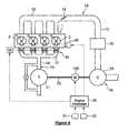
- the supercharged engine system comprises an internal combustion engine 1.
- the engine 1 has a plurality of cylinders 1a through 1d, not limited to but four cylinders in this embodiment, in its cylinder block.
- the cylinders 1a through 1d respectively have pistons therein, and the piston can reciprocate in the respective cylinder and is connected to a crankshaft to output torque.
- the engine 1 has four combustion chambers 2.
- the combustion chamber 2 is defined by a wall of the cylinder, the piston and a cylinder head. On the cylinder head of the each cylinder, there are provided at least one intake port and at least one exhaust port opening to the each combustion chamber 2.
- An intake valve 3 and an exhaust valve 4 are provided respectively in the intake port and the exhaust port and capable of shutting off (or controlling the opening of or through rate through) the ports from the combustion chamber. Further, on the cylinder head, at least one spark plug 5 and at least one fuel injector 6 are provided.
- An intake system 10 is connected to the engine 1 for supplying combustion air or fresh air to the combustion chamber 2.
- An exhaust system 15 is connected to the engine 1 for directing exhaust gas out of the combustion chamber 2.
- the intake system 10 comprises an intake manifold 12 having discrete intake passages 11 that are communicated respectively to the intake ports of the cylinders 1 a through 1 d.
- the intake system 10 further comprises a common intake passage 13 arranged upstream of the intake manifold 12.
- a throttle valve 14 is arranged in the common intake passage 13 for regulating the intake airflow.
- the exhaust system 15 comprises an exhaust manifold 17 having discrete exhaust passages 16 that are communicated respectively to the exhaust ports of the cylinders 1 a through 1d.
- the exhaust system 15 comprises a common exhaust passage 18 arranged downstream of the exhaust manifold 17.
- a turbocharger 20 and an electric supercharger 30 are provided for the engine 1, a turbocharger 20 and an electric supercharger 30 are provided.
- the turbocharger 20 comprises at least one turbine 21 which is rotationally driven at least partly with energy of the exhaust gas. It further comprises a compressor 23 connected to the turbine 21 through the shaft 22. The turbine 21 rotates and drives the compressor 23 to boost the intake air to the engine 1.
- the turbocharger 20 preferably is of a relatively large size and a high speed type showing a greater boost performance at a higher engine speed range.
- the turbine 21 preferably is arranged in the common exhaust passage 18.
- a waste gate passage 24 bypasses the turbine 21, and a waste gate valve 25 is arranged in the waste gate passage 24.
- the compressor 23 is arranged in the common intake passage 13.
- An intercooler 26 for cooling the boosted air preferably is provided in the common intake passage 13 downstream of the compressor 23.
- the electric supercharger 30 is arranged in the common intake passage 13 downstream of the intercooler 26.
- the throttle valve 14 is arranged in the common intake passage 13 downstream of the electric supercharger 30.
- the electric supercharger 30 comprises a supercharger with an impeller or the like and an electric motor for driving the supercharger.
- a bypass passage 31 preferably is provided as part of the intake passage 10 and bypasses the electric supercharger 30.
- a bypass control valve 32 which regulates or controls airflow in the bypass passage 31 and is driven by an actuator 33.
- variable exhaust volume system 40 and a variable valve timing system 48 are provided for increasing energy of exhaust gas supplied to the turbine 21 in an operating region where a boost performance of the turbocharger 20.
- the variable exhaust volume system 40 is able to vary a volume of the exhaust passage upstream of the turbine 21.
- the variable valve timing system 48 is able to vary closing timing of the exhaust valve 4.
- variable exhaust volume system 40 It comprises one or more volume chambers 42 and an exhaust volume control valve 43.
- the volume chambers 42 communicate to the respective discrete exhaust passages 16 of the exhaust manifold 17 through respective conduits 41.
- the variable volume valve 43 is capable of closing the corresponding conduit 41 and operated or driven preferably by a motor 46 through a common shaft 44, a gear 45 and the like.
- the variable volume valves 43 close the conduits 41, the communication between the discrete exhaust passages 16 and the volume chambers 42 is shut off, and the volume of the exhaust system 15 upstream of the turbine 21 is reduced.
- the variable volume valves 43 open the conduits 41, the communication is enabled, and the volume of the exhaust system 15 upstream of the turbine 21 is increased.
- the variable valve timing system 48 shown in Figure 1 has a variable cam timing mechanism which is capable of varying a phase of an exhaust camshaft with respect to the crankshaft (engine output shaft).
- the exhaust camshaft reciprocally drives the exhaust valves 4.
- Various structures of the variable cam timing mechanism are known and not shown herein. But, for example, a phase changing member is arranged between the camshaft and a cam pulley which receives a rotation of the crankshaft through a timing belt or chain, and the phase changing member preferably is hydraulically or electrically driven.
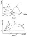
- variable valve timing system 48 is capable of defining a first exhaust valve timing EVT1 shown in a solid line and a second exhaust valve timing EVT2 which is retarded from the first exhaust valve timing EVT1 and shown in a broken line.
- the exhaust valve 4 opens at timing EO1 in a cylinder cycle and closes at timing EC1 in the cylinder cycle.
- the timing EO1 is earlier than a bottom dead center (BDC) of the cylinder cycle by a predetermined crank angle.
- the timing EC1 is around or near a top dead center (TDC) in the engine cycle.
- the exhaust valve 4 opens at timing E02 in a cylinder cycle and closes at timing EC2 in the cylinder cycle.
- the timing E02 is around or near the bottom dead center (BDC) of the cylinder cycle.
- the timing EC2 is later than (or retarded with respect to) the top dead center (TDC) of the cylinder cycle by a predetermined or predeterminable crank angle.
- an engine controller 50 for controlling various functions of the engine system.
- the engine controller 50 preferably comprises a microprocessor based control unit comprising a memory which stores programs and data, a central processing unit which processes the stored programs and data, and input/output terminals which inputs and outputs signals.
- the engine controller 50 receives the signals from one or more various sensors preferably including an accelerator position sensor 51 which detects a position of an accelerator pedal in a reflection of a desired engine output torque and an engine speed sensor 52 which (directly or indirectly) detects a rotational speed of the engine 1.
- the engine controller 50 controls one or more various actuators preferably including the electric motor of the electric supercharger 30, the actuator 33 of the bypass control valve 32 and the variable valve timing system 48.
- the engine controller 50 computes or determines amount of air inducted into the combustion chambers of the engine 1 preferably based on an intake air flow rate, an intake manifold pressure and others. Then, based on the computed air amount, the engine controller 50 computes or determines a fuel injection amount and/or a pulse width of duration of opening of the fuel injector 6 so as to achieve a desired air fuel ratio, for example a stoichiometric air fuel ratio depending on the fuel property.
- the electric supercharger 30 is not able to substantially boost the intake air to the engine 1, and the turbocharger 20 substantially exclusively boosts the intake air to the engine 1.
- the turbocharger 20 preferably is of the high speed type. Therefore, if the energy supplied to the turbine 21 were not increased, the engine output torque would drop in the mid or intermediate speed range (see a broken line of Figure 5) although the boosting performance would be improved in a region B2 at the higher speed side.
- the energy of exhaust gas supplied to the turbine 21 is increased, and the boosting effect of the turbocharger 20 is increased to increase the engine output torque.
- the exhaust volume control valve 43 is opened, and the variable valve timing system 48 is controlled so that the exhaust valve 4 opens at the retarded timing EO2, in the mid or intermediate speed range.
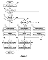
- FIG. 6 there is shown a flowchart of a routine the engine controller 50 executes.
- the routine proceeds to a step S1, and the engine controller 50 reads the one or more various signals or data.
- the routine proceeds to a step S2, and the engine controller 50 determines an engine operating condition based on the signals read at the step S1, and determines whether or not a desired engine output torque TQ, which preferably is predominantly based on the accelerator pedal position detected by the accelerator position sensor 51, is greater than a predetermined or predeterminable torque TQ 1 or not.
- the predetermined torque TQ 1 corresponds to that shown in Figure 5.
- the routine proceeds to a step S3 and determines whether or not the current engine speed NE detected by the engine speed sensor 52 is greater than a first predetermined or predeterminable engine speed NE 1 .
- the routine proceeds to a step S4, and the engine controller 50 controls the motor 46 of the variable exhaust volume system 40 to reduce the volume of the variable exhaust volume system 40 or to close the exhaust volume control valve 43 and shut off the discrete exhaust passages 16 from the volume chambers 40.
- the routine proceeds to a step S5, and the engine controller 50 controls the variable valve timing system 48 to set the retarded exhaust valve timing EVT2.
- the routine proceeds to a step S6, and controls the electric motor of the electric supercharger 30 to operate.
- the routine proceeds to a step S5, and the engine controller 50 controls the actuator 33 of the bypass control valve 32 to close the bypass passage 31, in order to boost the intake air to the engine 1 with the electric supercharger 30.
- the routine proceeds to a step S8 and determines whether or not the current engine speed NE is greater than a second predetermined or predeterminable engine speed NE 2 which is greater than the first predetermined or predeterminable engine speed NE 1 as shown in Figure 5.
- the routine proceeds to a step S9, and the engine controller 50 controls the motor 46 of the variable exhaust volume system 40 to reduce the volume of the variable exhaust volume system 40 or to close the exhaust volume control valve 43 and shut off the discrete exhaust passages 16 from the volume chambers 40.
- the routine proceeds to a step S10, and the engine controller 50 controls the variable valve timing system 48 to set the retarded exhaust cam phase EVT2.
- the routine proceeds to a step S11, and controls the electric motor of the electric supercharger 30 not to operate.
- the routine proceeds to a step S12, and the engine controller 50 controls the actuator 33 of the intake control valve 32 to open the bypass passage 31.
- the routine proceeds to a step S13, and the engine controller 50 controls the motor 46 of the variable exhaust volume system 40 to increase the volume of the variable exhaust volume system 40 or to open the exhaust volume control valve 43 and communicate the discrete exhaust passages 16 with the volume chambers 40.
- the routine proceeds to a step S14, and the engine controller 50 controls the variable valve timing system 48 to set the advanced exhaust cam phase EVT1. Further, the routine proceeds to the steps S11 and S12, and the engine controller 50 controls the actuators as described above.
- the routine proceeds to the steps 13, 14, 11 and then 12, and the engine controller 50 controls the actuators in the similar or substantially same way as is done when the engine 1 is in the higher speed range.
- the electric supercharger 30 is driven, and the boosting effect of the electric supercharger 30 can increase the engine output torque.
- the electric supercharger 30 preferably is not driven, and the turbocharger 20 boosts the intake air. Then, the intake control valve 32 opens the bypass passage 31, and the air boosted by the turbocharger 20 is supplied through the bypass passage 31 to the engine 1.
- variable exhaust volume system 40 decreases the volume of the exhaust system 15 upstream of the turbine 21, and the variable valve timing system 48 delays the opening timing of the exhaust valve 4.
- the energy of the exhaust gas supplied to the turbine 21 is increased, and the boosting effect of the turbocharger 20 is improved even though the turbocharger 20 is inherently fit to the higher speed range in terms of its efficiency.
- the exhaust energy decreases by the exhaust gas expansion until it reaches the turbine 21 is reduced.
- the exhaust volume control valve 43 of the variable exhaust volume system 40 is closed, and the volume of the exhaust system 15 upstream of the turbine 21 is reduced. As a result, the exhaust gas energy supplied to the turbine 21 is increased.
- the opening timing of the exhaust valve 4 As the opening timing of the exhaust valve 4 is retarded, a boost pressure increases due to the increase of blow-down energy.
- the opening timing of the exhaust valve 4 is retarded beyond the bottom dead center (BDC)
- the engine output torque is reduced particularly due to the pump loss increase because the exhaust pressure acts against the upward moving piston. Accordingly, the opening timing of the exhaust valve 4 around the bottom dead center (BDC) may be most effective for the torque increase by the intake air boost.
- the closing timing of the exhaust valve 4 is retarded at the substantially same time as (or concurrently to) the opening timing is because the variable valve timing system 40 retards the phase of the exhaust camshaft.
- an overlapping duration where both of the exhaust valve 4 and the intake valve 3 are opened is prolonged, thereby reducing the residual exhaust gas in the cylinders 2. Therefore, fresh air portion of the air charged in the cylinder 1 is increased, and the engine output torque which is produced by combusting the fresh air and fuel is increased.
- the exhaust volume control valve 43 of the variable exhaust volume system 40 is opened, and the volume of the exhaust system 15 upstream of the turbine 21 is increased.
- the opening timing of the exhaust valve 4 is advanced to the first timing EVT1.
- the exhaust pressure increase is suppressed. Therefore, in the higher speed range where the amount of exhaust gas is greater, the pump loss increase and possibility of engine knocking due to the exhaust pressure increase can be suppressed.
- the turbocharger 20 Even though the exhaust gas energy supplied to the turbine 21 is not particularly increased in the higher engine speed range, the turbocharger 20 itself fits to the higher speed range in terms of its operating efficiency, and the sufficient boosting effect can be obtained in the higher speed range.
- the exhaust gas pressure in the higher engine speed range depends on a size of the turbine. As the turbine size is greater, the exhaust gas pressure becomes lower. Accordingly, by using the turbocharger with greater turbine size, the exhaust pressure increase in the higher engine speed range can be suppressed, and the exhaust pressure can be maintained lower than the intake air pressure.
- the greater boost effect can be presented, and the engine output torque can be increased.
- the intake air pressure can be maintained higher than the exhaust gas pressure, thereby improving the boosting effect as well as fuel efficiency.
- variable exhaust volume system 40 and the variable valve timing system 48 are provided to increase the exhaust energy in the mid or intermediate engine speed range, only either one of them may be provided.
- variable valve timing system 4 preferably including the variable cam timing mechanism for the intake valves 3 may be provided as shown by a two-dotted line in Figure 1.
- the phase of the intake camshaft is advanced to advance the opening timing of the intake valve 3 in addition to the retard of the closing timing of the exhaust valve 4, the overlap duration where the both intake and exhaust valves are open is prolonged, thereby further reducing the residual exhaust gas.
- the closing timing of the intake valve 3 is advanced, and the blow back of the air from the cylinder to the intake manifold can be suppressed. As a result, fresh air portion of the air charged in the cylinder is increased, and the engine output torque which is produced by combusting the fresh air and fuel is increased.
- the electric supercharger 30 is independent from the turbocharger 20 as shown in Figure 1, a driving motor such as an electric motor 100 may be integrated into or coupled to the turbocharger 20 as shown in Figure 8.
- the electric motor 100 is configured to drive the shaft 22 which connects the turbine 21 and the compressor 23 of the turbocharger 23. When the electric motor 100 is driven, it assists the rotation of the compressor 23. In other words, the electric motor 100 and the compressor 23 function collectively as an electric supercharger.
- the electric motor 100 preferably is driven only in the lower engine speed range. In the mid and higher speed ranges, the turbocharger 20 boosts the intake air to the engine 1 with no assist of the electric motor 100.
- a turbocharger 60 comprises a twin-scroll turbine 61 which has a first scroll 61 a and a second scroll 61 b.
- the exhaust system 15 comprises a first exhaust system which directs the exhaust gas from the first and fourth cylinders 1a and 1d to the first scroll 61 a and a second exhaust system which directs the exhaust gas from the second and third cylinders 1b and 1 c to the second scroll 61 b.
- the combustion sequence of this engine 1 is the order of the cylinders #1-3-4-2. Therefore, each of the first and second scrolls 61 a and 61b receives the exhaust gas from the cylinders whose combustions are not one after another in a row.
- the first exhaust system comprises the discrete exhaust passages 16 from the first cylinder 1 a and the fourth cylinders 1 d and a first collecting passage 65a at an upstream end of which the two discrete passages merge.
- the second exhaust system comprises the discrete exhaust passages 16 from the second cylinder 1b and the third cylinders 1 c and a second collecting passages 65b at an upstream end of which the two discrete passages merge.
- a communication passage 66 preferably is arranged between the first collecting passage 65a and the second collecting passage 65b and connects these two passages.
- a communication control valve 67 is arranged in the connecting passage 66 and controllably closes it. The first and second exhaust systems, the communication passage 66 and the communication control valve 67 collectively regulate the energy of the exhaust gas supplied to the turbine 61.
- the electric supercharger 30 may be independent from the turbocharger 60 as illustrated by a solid line in Figure 9, or alternatively the electric motor 100 may be integrated into or coupled to the turbocharger 60 as illustrated by a two-dotted line in Figure 9.
- FIG. 10 there is shown a flowchart of a routine the engine controller 50 executes in accordance with the second embodiment.
- the routine proceeds to a step S101, and the engine controller 50 reads the various signals.
- the routine proceeds to a step S102, and the engine controller 50 determines an engine operating condition based on the signals read at the step S101, and determines whether or not a desired engine output torque is greater than the predetermined or predeterminable torque TQ1.
- the routine proceeds to a step S103 and determines whether or not the current engine speed NE is greater than the first predetermined or predeterminable engine speed NE1.
- the routine proceeds to a step S104, and the engine controller 50 controls the communication control valve 67 to shut the communication passage 66.
- the routine proceeds to a step S105, and the engine controller 50 controls the electric motor of the electric supercharger 30 to operate.
- the routine proceeds to a step S106, and the engine controller 50 controls the actuator 33 of the intake control valve 32 to close the bypass passage 31, in order to boost the intake air to the engine 1 with the electric supercharger 30.
- the routine proceeds to a step S107 and determines whether or not the current engine speed NE is greater than the second predetermined or predeterminable engine speed NE2.
- the routine proceeds to a step S108, and the engine controller 50 controls the communication control valve 67 to close the communication passage 66.
- the routine proceeds to a step S109, and the engine controller 50 controls the electric motor of the electric supercharger 30 not to operate. Then, the routine proceeds to a step S110, and the engine controller 50 controls the actuator 33 of the intake control valve 32 to open the bypass passage 31.
- the routine proceeds to a step S113, and the engine controller 50 controls the communication control valve 67 to open the communication passage 66 thereby communicating the first and second collecting passages 65a and 65b. Further, the routine proceeds to the steps S109 and S110, and the engine controller 50 controls the actuators as described above.
- the routine proceeds to the steps 112, 109, and then 110, and the engine controller 50 controls the actuators in the same way as is done when the engine 1 is in the higher speed range.
- the electric supercharger 30 in the lower engine speed range, the electric supercharger 30 is driven. In the mid and higher speed ranges, the electric supercharger 30 is not driven, and the turbocharger 20 boosts the intake air.
- the communication control valve 67 closes the communication passage 66 so that the first and second collecting passages 65a and 65b are shut from each other.
- exhaust gases from the first collecting passage 65a and the second collecting passage 65b are separately directed to the first and second scroll 61 a and 61 b of the turbine 61, thereby preventing interference between the first and second exhaust systems and maintaining pulsations of the exhaust gas. This leads to increasing the exhaust gas energy supplied to the turbine 60 to improve the boosting effect and increase the engine output torque.
- the communication control valve 67 is opened, thereby to interfere the pulsations of the exhaust gas and to reduce the exhaust pressure. Accordingly, in the higher engine speed range where the exhaust gas flow is greater, the exhaust pressure increase may be suppressed, thereby to reduce the pump loss, and to more effectively boost the intake air to the engine 1.
- a turbocharger 70 comprises a turbine 71 arranged in the exhaust system, a compressor 73 arranged in the intake system, a shaft connecting the turbine 71 and the compressor 73, and a variable vanes arranged at the intake side of the turbine 71.
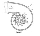
- the turbine 71 comprises a turbine chamber 74 into which the exhaust gas is directed, and a plurality of moveable vanes 76 arranged to surround turbine blades of a turbine wheel 75.
- the moveable vanes 76 can pivot about shafts 77, thereby to change an opening degree of the vanes 76 or a sectional area or an opening degree of nozzles defined by the adjacent vanes 76.
- the opening degree of the vanes 76 is reduced.
- a flow rate of the exhaust gas through the vane nozzles is increased, and a flow direction of the exhaust gas through the vane nozzles is directed closer to a tangential direction of the turbine wheel 75, thereby improving operational efficiency of the turbine 71 and eventually boosting efficiency of the turbocharger 70.
- the opening of the vane nozzles are increased.
- the opening degree of the vane nozzles are caused greater especially in the higher engine speed range, the exhaust gas flow may be maintained greater, and the boosting efficiency of the turbocharger 70 may be improved.
- a vane actuator 80 is arranged in the vicinity of or integrated into the turbocharger 70 and rotates or actuates the shafts 77 of the moveable vanes 76 and changes angular positions and the opening degree of the moveable vanes.
- the vane actuator 80 preferably comprises a vacuum pusher 81, a solenoid valve 82 arranged in a vacuum supply conduit to the vacuum pusher 81, a vacuum pump 83 as a vacuum supply source, and the like.
- the solenoid valve 82 is controlled by the engine controller 50, thereby changing the vacuum in the pusher 81 and eventually the opening degree of the moveable vanes 76.
- the electric supercharger 30 may be independent from the turbocharger 70 as shown by a solid line in Figure 12, or the electric motor 100 may be integrated into or coupled to the turbocharger 70 as shown by a two-dotted line in Figure 12.
- the opening degree of the moveable vanes 76 is reduced or the nozzles are restricted to improve the boost performance.
- the pump loss would be increased, the engine knocking would be more likely to occur, and the torque increase could not be achieved.
- the electric supercharger 30 is driven to increase the intake pressure, and the opening degree of the moveable vanes 76 is adjusted so that the exhaust pressure is reduced below the intake pressure.
- the turbocharger 70 boosts the intake air to the engine 1, while the electric supercharger 30 is not driven, the opening degree of the moveable vanes 76 is adjusted so that the vane nozzles are restricted to the extent that the exhaust pressure does not exceed the intake pressure.
- the turbocharger 70 boosts the intake air to the engine 1, while the moveable vanes 76 are fully opened.
- the engine system comprises an internal combustion engine, a supercharging system having at least one supercharger to boost intake air to the internal combustion engine, a turbine, and a motor.
- the turbine receives an exhaust gas flow from an exhaust system of the internal combustion engine and is capable of at least partly driving the supercharging system.
- the motor is capable of at least partly driving the supercharging system.
- the method comprises operating the exhaust system in a first exhaust state and operating the motor in a first motor state when a speed of the internal combustion engine is below a first engine speed, operating the exhaust system in the first exhaust state and operating the motor in a second motor state where power to drive the motor is reduced from that in the first motor state when the speed of the internal combustion engine is between the first engine speed and a second engine speed which greater the said first engine speed, and operating the exhaust system in a second exhaust state where energy transmitted from the internal combustion engine to the turbine is reduced from that in the first exhaust state and operating the motor in the second motor state when the speed of the internal combustion engine is above the second engine speed. Accordingly, the maximum torque can be increased while maintaining the system efficiency over the entire engine speed range.
Landscapes
- Engineering & Computer Science (AREA)
- Chemical & Material Sciences (AREA)
- Combustion & Propulsion (AREA)
- Mechanical Engineering (AREA)
- General Engineering & Computer Science (AREA)
- Supercharger (AREA)
- Output Control And Ontrol Of Special Type Engine (AREA)
- Combined Controls Of Internal Combustion Engines (AREA)
- Electrical Control Of Air Or Fuel Supplied To Internal-Combustion Engine (AREA)
Abstract
Description
- The present description generally relates to a supercharged engine, and more particularly relates to control a supercharging system, having a motor and an exhaust gas turbine both to drive a supercharger to boost intake air to the engine.
- There is known and presented, for example in
Japanese Patent Application Publication no. 2006-77604A - Generally speaking, the turbine efficiency is higher when the exhaust gas flow is greater. On the other hand, when the exhaust gas flow is relatively low, the turbine efficiency may not be sufficient to obtain a desired boost pressure. To improve the turbine efficiency at the low exhaust gas flow range, the turbine of the '604 publication has a variable geometry nozzle that variably regulates exhaust gas flow to a turbine wheel. Sectional area of the conduit directing the exhaust gas to the turbine is changed by controlling a position of the variable geometry nozzle to meet an actual boost pressure to a target boost pressure.
- When the sectional area of the turbine conduit is reduced, exhaust gas flow rate is increased and the efficiency of the turbine is increased. However, then, a pressure at the exhaust manifold between the engine and the nozzle is increased. The higher exhaust manifold pressure creates greater resistive force against an upward movement of the piston during an exhaust stroke of a cylinder cycle, or it creates higher pump loss during the exhaust stroke. On the other hand, when the intake manifold pressure is lower, the piston receives greater resistive force against its downward movement or during an intake stroke of a cylinder cycle. In other words, the lower intake manifold pressure translates into greater pump loss during the intake stroke. Therefore, as the exhaust manifold pressure is greater than the intake manifold, the pump loss increases, and the supercharging system efficiency decreases.
- To increase the supercharging system efficiency, the '604 publication provides the electric motor to drive the supercharger in addition to the turbine. When the engine is in a predetermined operating range, the motor is driven, the sectional area of the conduit is increased, and the exhaust manifold pressure is reduced. Then, the motor partly drives the supercharger and compensates the reduced power from the turbine to drive the supercharger.
- The method of '604 publication can increase the supercharging system efficiency when the electric motor drives the supercharger in the predetermined engine operating range. The electric motor is basically driven in the mid torque range. It is not driven at the full load over the entire engine speed range. If the prior art method is applied for a supercharging system having a turbine whose efficiency is higher at the higher engine speed range, it can not produce the supposedly maximum torque at the lower speed range. In addition, at the higher engine speed range, the electric motor is driven and is supposed to make less assist for the supercharging system, and the system can consume the unnecessarily greater amount of electric energy.
- Therefore, it is an object of the invention to improve the performance and the efficiency of an supercharged engine system.
- This object is solved according to the invention by the features of the independent claims. Preferred embodiments are subject of the dependent claims.
- According to an aspect of the present description, there is provided a method of controlling an engine system comprising an internal combustion engine, a supercharging system having at least one supercharger to boost intake air to said internal combustion engine, a turbine, and a motor, wherein said turbine receives an exhaust gas flow from an exhaust system of said internal combustion engine and is capable of at least partly driving said supercharging system, and wherein said motor is capable of at least partly driving said supercharging system, the method comprising:
- operating said exhaust system in a first exhaust state and operating said motor in a first motor state when a speed of said internal combustion engine is below a first engine speed;
- operating said exhaust system in said first exhaust state and operating said motor in a second motor state where power to drive said motor is reduced from that in said first motor state when the speed of said internal combustion engine is between said first engine speed and a second engine speed, said second engine speed being greater than said first engine speed; and
- operating said exhaust system in a second exhaust state where energy transmitted from said internal combustion engine to said turbine is reduced from that in said first exhaust state and operating said motor in said second motor state when the speed of said internal combustion engine is above said second engine speed.
- According to a further aspect, the method further comprises:
- opening an exhaust valve of said internal combustion engine at a first exhaust open timing in a cylinder cycle during said first exhaust state; and
- opening said exhaust valve at a second exhaust open timing which is earlier than said first exhaust open timing in the cylinder cycle during said second exhaust state.
- According to a further aspect, the method further comprises:
- closing said exhaust valve after opening of an intake valve of said internal combustion engine in the cylinder cycle by a first overlap period during said first exhaust state; and
- closing said exhaust valve after opening of said intake valve in the cylinder cycle by a second overlap period that less than said first overlap period during said second exhaust state.
- According to a further aspect, the method further comprises:
- closing said exhaust valve at a first exhaust close timing in the cylinder cycle during said first exhaust state; and
- closing said exhaust valve at a second exhaust close timing in the cylinder cycle during said second exhaust state, said second exhaust close timing being earlier than said first exhaust close timing.
- According to a further aspect, the method further comprises:
- opening said intake valve at a first intake open timing in the cylinder cycle during said first exhaust state; and
- opening said intake valve at a second intake open timing in the cylinder cycle during said second exhaust state, said second intake open timing being later than said first intake open timing.
- According to a further aspect, the method further comprises:
- making a first volume of said exhaust system between said internal combustion engine and said turbine in said first exhaust state; and
- making a second volume of said exhaust system between said internal combustion engine and said turbine in said second exhaust state, said second volume being greater than said first volume.
- According to a further aspect, the method further comprises:
- making a first volume of said exhaust system between said internal combustion engine and said turbine in said first exhaust state; and
- making a second volume of said exhaust system between said internal combustion engine and said turbine in said second exhaust state, said second volume being greater than said first volume.
- According to a further aspect, said internal combustion engine has a plurality of cylinders, wherein said exhaust system has a first discrete passage connecting between a first of said cylinders and said turbine, a second discrete passage connecting between a second of said cylinders and said turbine, and a connecting passage connecting said first and second discrete passages, the method further comprising:
- closing said connecting passage during said first exhaust state; and
- opening said connecting passage during said second exhaust state.
- According to a further aspect, said exhaust system has a variable nozzle capable of regulating exhaust gas flow to said turbine, the method further comprising:
- positioning said variable nozzle so as to regulate more the exhaust gas flow during said first exhaust state than during said second exhaust gas state.
- According to a further aspect, said supercharging system comprises a first supercharger driven by said motor, a second supercharger driven by said turbine and a bypass passage bypassing said first supercharger, the method further comprising:
- opening said bypass passage more during said second motor state than during said first motor state.
- According to a further aspect, the method further comprises:
- supplying power to drive said motor during said first motor state; and
- shutting off the power to drive said motor during said second motor state.
- According to a further aspect, said supercharging system comprises a first supercharger driven by said motor, a second supercharger driven by said turbine and a bypass passage bypassing said first supercharger, the method further comprising:
- closing said bypass passage during said first motor state; and
- opening said bypass passage during said second motor state.
- According to a further aspect, the method further comprises:
- opening an exhaust valve at a first exhaust open timing during a cylinder cycle in said first exhaust state; and
- opening said exhaust valve at a second exhaust open timing which is earlier than said first exhaust open timing during the cylinder cycle in said second exhaust state.
- According to a further aspect, the method further comprises:
- opening an exhaust valve at a first exhaust open timing during a cylinder cycle in said first exhaust state; and
- opening said exhaust valve at a second exhaust open timing which is earlier than said first exhaust open timing during the cylinder cycle in said second exhaust state.
- According to a further aspect of the invention, there is provided a computer program product, in particular embodied in a computer-readable storage medium, as a signal or as a data stream, which, when loaded and executed on a suitable system performs the steps of a method according to any one of the preceding aspects.
- According to a further aspect of the invention, there is provided a system comprising:
- an internal combustion engine;
- an exhaust system variably directing an exhaust gas flow from said internal combustion engine to downstream;
- a supercharging system having at least one supercharger to boost intake air to said internal combustion engine, a turbine which receives an exhaust gas flow from said exhaust system and is capable of at least partly driving said at least one supercharger, and a motor which is capable of at least partly driving said at least one supercharger; and
- a controller configured to:
- operate said exhaust system in a first exhaust state and operate said motor in a first motor state when a speed of said internal combustion engine is below a first engine speed;
- operate said exhaust system in said first exhaust state and operate said motor in a second motor state where power to drive said motor is reduced from that in said first motor state when the speed of said internal combustion engine is between said first engine speed and a second engine speed, said second engine speed being greater than said first engine speed; and
- operate said exhaust system in a second exhaust state where energy transmitted from said internal combustion engine to said turbine is reduced from that in said first exhaust state and operate said motor in said second motor state when the speed of said internal combustion engine is above said second engine speed.
- According to a further aspect, the system further comprises:
- a volume chamber capable of communicating with said exhaust system between said internal combustion engine and said turbine; and
- an exhaust control valve capable of shutting off said volume chamber from said exhaust system, and
- According to a further aspect, said internal combustion engine has a plurality of cylinders, wherein said exhaust system has a first discrete passage connecting between a first of said cylinders and said turbine, a second discrete passage connecting between a second of said cylinders and said turbine, a connecting passage connecting said first and second discrete passages, and an exhaust control valve arranged in said connecting passage, and wherein said controller is further configured to:
- control said exhaust control valve to close said connecting passage during said first exhaust state; and
- control said exhaust control valve to open said connecting passage during said second exhaust sate.
- According to a further aspect, said exhaust system has a variable nozzle capable of regulating exhaust gas flow to said turbine, and wherein said controller is further configured to:
- control said variable nozzle to regulate more the exhaust gas flow during said first exhaust state than during said second exhaust gas state.
- According to a further aspect, said supercharging system comprises a first supercharger driven by said motor, a second supercharger driven by said turbine, a bypass passage bypassing said first supercharger and a bypass control valve capable of closing said bypass passage, and wherein said controller is further configured to:
- control said bypass control valve to close said bypass passage during said first motor state; and
- control said bypass control valve to open said bypass passage during said second motor state.
- According to a further aspect, the system further comprises a power source capable of supplying power to said motor, and wherein said controller is further configured to:
- control said power source to supply power to drive said motor during said first motor state; and
- control said power source to shut off the power to drive said motor during said second motor state. Accordingly, there is provided, in one aspect of the present description, a method of controlling an engine system. The engine system comprises an internal combustion engine, a supercharging system having at least one supercharger to boost intake air to the internal combustion engine, a turbine, and a motor. The turbine receives an exhaust gas flow from an exhaust system of the internal combustion engine and is capable of at least partly driving the supercharging system. The motor is capable of at least partly driving the supercharging system. The method comprises operating the exhaust system in a first exhaust state and operating the motor in a first motor state when a speed of the internal combustion engine is below a first engine speed, operating the exhaust system in the first exhaust state and operating the motor in a second motor state where power to drive the motor is reduced from that in the first motor state when the speed of the internal combustion engine is between the first engine speed and a second engine speed which greater the said first engine speed, and operating the exhaust system in a second exhaust state where energy transmitted from the internal combustion engine to the turbine is reduced from that in the first exhaust state and operating the motor in the second motor state when the speed of the internal combustion engine is above the second engine speed.
- According to the method of the first aspect of the present description, the inventors herein ingeniously configured operations of the motor and the exhaust system in accordance with the engine speed so that the maximum torque can be obtained while maintaining the system efficiency over the entire engine speed range. In particular, the power to drive the motor is made greater and the exhaust system is operated in the first exhaust state where the energy transmitted from the internal combustion engine to the turbine is greater, in a lower engine speed range below the first engine speed, where the turbine efficiency may not be sufficient even if the energy transmitted is increased. Therefore, the engine output torque can be maximized in the lower engine speed range.
- The power to drive the motor is reduced, and the exhaust system is still in the first exhaust state, in a mid engine speed range between the first and second engine speeds, where the motor operation may not increase the intake air boost because the intake air flow is greater than in the lower engine speed range, and where the turbine efficiency may be sufficient if the energy transmitted to the turbine is still greater. Therefore, the engine output torque can be maximized, and at the same time, the energy spent to drive the motor can be reduced, in the mid engine speed range.
- The power to drive the motor is continued to be less, and the exhaust system is operated in the second turbine state where the energy transmitted from the engine to the turbine is reduced, in a higher engine speed range above the third engine speed, where the first exhaust state might decrease the engine efficiency, for example, causing the pump loss because of the greater exhaust manifold pressure. Therefore, the engine output torque can be maximized, and at the same time, the engine efficiency can be maintained, in the higher speed range.
- As such, the maximum torque can be obtained while maintaining the system efficiency over the entire engine speed range.
- In embodiments, an exhaust valve of the internal combustion engine may be opened later in the cylinder cycle during the first exhaust state than during the second exhaust state so that peak exhaust gas pressure may be increased during the first exhaust state. Therefore, the energy transmitted from the engine to the turbine may be increased during the first exhaust state.
- Further in the embodiments, the engine system may comprise a volume chamber capable of communicating with the exhaust system between the internal combustion engine and the turbine, and an exhaust control valve capable of shutting off the volume chamber from the exhaust system. The exhaust control valve may be controlled to shut off the volume chamber from the exhaust system so as to reduce the volume between the engine and the turbine during the first exhaust state. Therefore, the pressure decrease of the exhaust gas prior to reaching the turbine may be reduced during the first exhaust state.
- In the embodiments, the internal combustion engine may have a plurality of cylinders, and the exhaust system may have a first discrete passage a second discrete passage connecting between a second of the cylinders and the turbine, a connecting passage connecting the first and second discrete passages, and an exhaust control valve arranged in the connecting passage. The exhaust control valve may close the connecting passage during the first exhaust state so that the volume between the cylinder and the turbine may be reduced and the pressure decrease of the exhaust gas from the individual cylinders may be reduced during the first exhaust state.
- Further, in the embodiments, the exhaust system may have a variable nozzle capable of regulating exhaust gas flow to the turbine. The variable nozzle may regulate more the exhaust gas flow so as to increase the power transmitted from the engine to the turbine during the first exhaust state.
- The advantages described herein will be more fully understood by reading examples of embodiments in which the above aspects are used to advantage, referred to herein as the Detailed Description, with reference to the drawings. It should be understood that even though embodiments are separately described, single features thereof may be combined to additional embodiments.
- Figure 1 shows a schematic view of a supercharged engine system according to a first embodiment of the present description;
- Figure 2 shows a partially cross sectional view of an exhaust system according to the first embodiment;
- Figure 3 shows a cross sectional view of a variable exhaust volume system according to the first embodiment;
- Figure 4 shows lifts of intake and exhaust valves with variable exhaust valve timing in accordance with the first embodiment;
- Figure 5 shows different engine operating regions with different boosting performances for a supercharged engine system with an electric supercharger and a turbocharger;
- Figure 6 shows a flowchart of a control routine executed according to the first embodiment;
- Figure 7 are graphs of engine output torque and intake air pressure versus opening timing of exhaust valve for a supercharged engine;
- Figure 8 shows a schematic view of a supercharged engine system according to an embodiment alternative to the first embodiment;
- Figure 9 shows a schematic view of a supercharged engine system according to a second embodiment of the present description;
- Figure 10 shows a flowchart of a control routine executed according to the second embodiment;
- Figure 11 shows a schematic view of a supercharged engine system having a variable geometry turbine (VGT) in accordance with a third embodiment of the present description; and
- Figure 12 shows a detail view of the variable geometry turbine of the third embodiment.
- Embodiments of the present description will now be described with reference to the drawings, starting with Figure 1, which shows an overall construction of supercharged engine system in accordance with a first embodiment.
- The supercharged engine system comprises an
internal combustion engine 1. Theengine 1 has a plurality ofcylinders 1a through 1d, not limited to but four cylinders in this embodiment, in its cylinder block. Thecylinders 1a through 1d respectively have pistons therein, and the piston can reciprocate in the respective cylinder and is connected to a crankshaft to output torque. Theengine 1 has fourcombustion chambers 2. Thecombustion chamber 2 is defined by a wall of the cylinder, the piston and a cylinder head. On the cylinder head of the each cylinder, there are provided at least one intake port and at least one exhaust port opening to the eachcombustion chamber 2. Anintake valve 3 and an exhaust valve 4 are provided respectively in the intake port and the exhaust port and capable of shutting off (or controlling the opening of or through rate through) the ports from the combustion chamber. Further, on the cylinder head, at least onespark plug 5 and at least onefuel injector 6 are provided. - An
intake system 10 is connected to theengine 1 for supplying combustion air or fresh air to thecombustion chamber 2. Anexhaust system 15 is connected to theengine 1 for directing exhaust gas out of thecombustion chamber 2. Theintake system 10 comprises anintake manifold 12 havingdiscrete intake passages 11 that are communicated respectively to the intake ports of thecylinders 1 a through 1 d. Theintake system 10 further comprises acommon intake passage 13 arranged upstream of theintake manifold 12. Athrottle valve 14 is arranged in thecommon intake passage 13 for regulating the intake airflow. On the other hand, theexhaust system 15 comprises anexhaust manifold 17 havingdiscrete exhaust passages 16 that are communicated respectively to the exhaust ports of thecylinders 1 a through 1d. Further, theexhaust system 15 comprises acommon exhaust passage 18 arranged downstream of theexhaust manifold 17. Also for theengine 1, aturbocharger 20 and anelectric supercharger 30 are provided. - The
turbocharger 20 comprises at least oneturbine 21 which is rotationally driven at least partly with energy of the exhaust gas. It further comprises acompressor 23 connected to theturbine 21 through theshaft 22. Theturbine 21 rotates and drives thecompressor 23 to boost the intake air to theengine 1. Theturbocharger 20 preferably is of a relatively large size and a high speed type showing a greater boost performance at a higher engine speed range. - The
turbine 21 preferably is arranged in thecommon exhaust passage 18. Awaste gate passage 24 bypasses theturbine 21, and awaste gate valve 25 is arranged in thewaste gate passage 24. Thecompressor 23 is arranged in thecommon intake passage 13. Anintercooler 26 for cooling the boosted air preferably is provided in thecommon intake passage 13 downstream of thecompressor 23. - The
electric supercharger 30 is arranged in thecommon intake passage 13 downstream of theintercooler 26. Thethrottle valve 14 is arranged in thecommon intake passage 13 downstream of theelectric supercharger 30. Theelectric supercharger 30 comprises a supercharger with an impeller or the like and an electric motor for driving the supercharger. - A
bypass passage 31 preferably is provided as part of theintake passage 10 and bypasses theelectric supercharger 30. There is provided, in thebypass passage 31, abypass control valve 32 which regulates or controls airflow in thebypass passage 31 and is driven by anactuator 33. - I n this embodiment, a variable
exhaust volume system 40 and a variablevalve timing system 48 are provided for increasing energy of exhaust gas supplied to theturbine 21 in an operating region where a boost performance of theturbocharger 20. The variableexhaust volume system 40 is able to vary a volume of the exhaust passage upstream of theturbine 21. The variablevalve timing system 48 is able to vary closing timing of the exhaust valve 4. - Referring to Figures 2 and 3, there is shown a detail of the variable
exhaust volume system 40. It comprises one ormore volume chambers 42 and an exhaustvolume control valve 43. Thevolume chambers 42 communicate to the respectivediscrete exhaust passages 16 of theexhaust manifold 17 throughrespective conduits 41. Thevariable volume valve 43 is capable of closing thecorresponding conduit 41 and operated or driven preferably by amotor 46 through acommon shaft 44, agear 45 and the like. When thevariable volume valves 43 close theconduits 41, the communication between thediscrete exhaust passages 16 and thevolume chambers 42 is shut off, and the volume of theexhaust system 15 upstream of theturbine 21 is reduced. On the other hand, when thevariable volume valves 43 open theconduits 41, the communication is enabled, and the volume of theexhaust system 15 upstream of theturbine 21 is increased. - The variable
valve timing system 48 shown in Figure 1 has a variable cam timing mechanism which is capable of varying a phase of an exhaust camshaft with respect to the crankshaft (engine output shaft). The exhaust camshaft reciprocally drives the exhaust valves 4. Various structures of the variable cam timing mechanism are known and not shown herein. But, for example, a phase changing member is arranged between the camshaft and a cam pulley which receives a rotation of the crankshaft through a timing belt or chain, and the phase changing member preferably is hydraulically or electrically driven. - As shown in Figure 4, the variable
valve timing system 48 is capable of defining a first exhaust valve timing EVT1 shown in a solid line and a second exhaust valve timing EVT2 which is retarded from the first exhaust valve timing EVT1 and shown in a broken line. With the first exhaust valve timing EVT1, the exhaust valve 4 opens at timing EO1 in a cylinder cycle and closes at timing EC1 in the cylinder cycle. The timing EO1 is earlier than a bottom dead center (BDC) of the cylinder cycle by a predetermined crank angle. The timing EC1 is around or near a top dead center (TDC) in the engine cycle. On the other hand, with the second exhaust valve timing EVT2, the exhaust valve 4 opens at timing E02 in a cylinder cycle and closes at timing EC2 in the cylinder cycle. The timing E02 is around or near the bottom dead center (BDC) of the cylinder cycle. The timing EC2 is later than (or retarded with respect to) the top dead center (TDC) of the cylinder cycle by a predetermined or predeterminable crank angle. - Referring back to Figure 1, an
engine controller 50 is provided for controlling various functions of the engine system. Theengine controller 50 preferably comprises a microprocessor based control unit comprising a memory which stores programs and data, a central processing unit which processes the stored programs and data, and input/output terminals which inputs and outputs signals. Theengine controller 50 receives the signals from one or more various sensors preferably including anaccelerator position sensor 51 which detects a position of an accelerator pedal in a reflection of a desired engine output torque and anengine speed sensor 52 which (directly or indirectly) detects a rotational speed of theengine 1. On the other hand, in accordance with the received signals, theengine controller 50 controls one or more various actuators preferably including the electric motor of theelectric supercharger 30, theactuator 33 of thebypass control valve 32 and the variablevalve timing system 48. - The
engine controller 50 computes or determines amount of air inducted into the combustion chambers of theengine 1 preferably based on an intake air flow rate, an intake manifold pressure and others. Then, based on the computed air amount, theengine controller 50 computes or determines a fuel injection amount and/or a pulse width of duration of opening of thefuel injector 6 so as to achieve a desired air fuel ratio, for example a stoichiometric air fuel ratio depending on the fuel property. - Referring to Figure 5, there are shown various effects to boost the intake air to the
engine 1 in the various engine operating regions. In engine operating regions A and B where an engine output torque TQ is greater than a certain (predetermined or predeterminable) engine torque TQ1, the boosting effect can be observed. In other words, below the engine torque TQ1, theengine 1 can produce the desired torque without boosting the intake air. In the region A, the boosting effect from theelectric supercharger 30 overcomes the boosting effect from theturbocharger 20. In the region B, the boosting effect from theelectric supercharger 30 overcomes the boosting effect from theturbocharger 20. In a lower speed side A1 of the region A, theturbocharger 20 barely boosts the intake air, and basically theelectric supercharger 30 exclusively boosts the intake air. On the other hand, in a higher speed side A2 of the region A, theturbocharger 20 boosts the intake air to some extent, and both of theelectric supercharger 30 and theturbocharger 20 show the boosting effect simultaneously. - In the region B or in a mid or intermediate speed range and a higher speed range at the higher load side, the
electric supercharger 30 is not able to substantially boost the intake air to theengine 1, and theturbocharger 20 substantially exclusively boosts the intake air to theengine 1. In this embodiment, theturbocharger 20 preferably is of the high speed type. Therefore, if the energy supplied to theturbine 21 were not increased, the engine output torque would drop in the mid or intermediate speed range (see a broken line of Figure 5) although the boosting performance would be improved in a region B2 at the higher speed side. In the contrary, in this embodiment, in the mid or intermediate speed range, the energy of exhaust gas supplied to theturbine 21 is increased, and the boosting effect of theturbocharger 20 is increased to increase the engine output torque. In particular, in the mid or intermediate speed range, the exhaustvolume control valve 43 is opened, and the variablevalve timing system 48 is controlled so that the exhaust valve 4 opens at the retarded timing EO2, in the mid or intermediate speed range. - Referring to Figure 6, there is shown a flowchart of a routine the
engine controller 50 executes. After the start, the routine proceeds to a step S1, and theengine controller 50 reads the one or more various signals or data. Then, the routine proceeds to a step S2, and theengine controller 50 determines an engine operating condition based on the signals read at the step S1, and determines whether or not a desired engine output torque TQ, which preferably is predominantly based on the accelerator pedal position detected by theaccelerator position sensor 51, is greater than a predetermined or predeterminable torque TQ1 or not. The predetermined torque TQ1 corresponds to that shown in Figure 5. - When it is determined at the step S2 that the desired engine torque TQ is greater than the predetermined or predeterminable torque TQ1, which means that the intake air boost is required, the routine proceeds to a step S3 and determines whether or not the current engine speed NE detected by the
engine speed sensor 52 is greater than a first predetermined or predeterminable engine speed NE1. When it is determined at the step S3 that the engine speed NE is not greater than the first predetermined or predeterminable speed NE1, which means that theengine 1 is in the lower speed range, the routine proceeds to a step S4, and theengine controller 50 controls themotor 46 of the variableexhaust volume system 40 to reduce the volume of the variableexhaust volume system 40 or to close the exhaustvolume control valve 43 and shut off thediscrete exhaust passages 16 from thevolume chambers 40. After the step S4, the routine proceeds to a step S5, and theengine controller 50 controls the variablevalve timing system 48 to set the retarded exhaust valve timing EVT2. Further, the routine proceeds to a step S6, and controls the electric motor of theelectric supercharger 30 to operate. Then, the routine proceeds to a step S5, and theengine controller 50 controls theactuator 33 of thebypass control valve 32 to close thebypass passage 31, in order to boost the intake air to theengine 1 with theelectric supercharger 30. - When it is determined at the step S3 that the engine speed NE is greater than the first predetermined or predeterminable engine speed NE1, the routine proceeds to a step S8 and determines whether or not the current engine speed NE is greater than a second predetermined or predeterminable engine speed NE2 which is greater than the first predetermined or predeterminable engine speed NE1 as shown in Figure 5. When it is determined at the step S8 that the current engine speed NE is not greater than the second predetermined or predeterminable engine speed NE2, which means that the
engine 1 is in the mid or intermediate speed range, the routine proceeds to a step S9, and theengine controller 50 controls themotor 46 of the variableexhaust volume system 40 to reduce the volume of the variableexhaust volume system 40 or to close the exhaustvolume control valve 43 and shut off thediscrete exhaust passages 16 from thevolume chambers 40. After the step S9, the routine proceeds to a step S10, and theengine controller 50 controls the variablevalve timing system 48 to set the retarded exhaust cam phase EVT2. Further, the routine proceeds to a step S11, and controls the electric motor of theelectric supercharger 30 not to operate. Then, the routine proceeds to a step S12, and theengine controller 50 controls theactuator 33 of theintake control valve 32 to open thebypass passage 31. - When it is determined at the step S8 that the current engine speed NE is greater than the second predetermined or predeterminable engine speed NE2, which means that the
engine 1 is in the higher speed range, the routine proceeds to a step S13, and theengine controller 50 controls themotor 46 of the variableexhaust volume system 40 to increase the volume of the variableexhaust volume system 40 or to open the exhaustvolume control valve 43 and communicate thediscrete exhaust passages 16 with thevolume chambers 40. After the step S13, the routine proceeds to a step S14, and theengine controller 50 controls the variablevalve timing system 48 to set the advanced exhaust cam phase EVT1. Further, the routine proceeds to the steps S11 and S12, and theengine controller 50 controls the actuators as described above. - When it is determined at the step S2 that the desired engine output torque TQ is not greater than the predetermined or predeterminable engine torque TQ1, which means that the intake air boost is not required, the routine proceeds to the
steps engine controller 50 controls the actuators in the similar or substantially same way as is done when theengine 1 is in the higher speed range. - According to the present embodiment described above, in the lower engine speed range where the intake air boost by the
turbocharger 20 is not enough, theelectric supercharger 30 is driven, and the boosting effect of theelectric supercharger 30 can increase the engine output torque. - In the mid or intermediate and higher engine speed range, the
electric supercharger 30 preferably is not driven, and theturbocharger 20 boosts the intake air. Then, theintake control valve 32 opens thebypass passage 31, and the air boosted by theturbocharger 20 is supplied through thebypass passage 31 to theengine 1. - In the mid or intermediate engine speed range, the variable
exhaust volume system 40 decreases the volume of theexhaust system 15 upstream of theturbine 21, and the variablevalve timing system 48 delays the opening timing of the exhaust valve 4. As a result, the energy of the exhaust gas supplied to theturbine 21 is increased, and the boosting effect of theturbocharger 20 is improved even though theturbocharger 20 is inherently fit to the higher speed range in terms of its efficiency. - In more detail, as the volume of the
exhaust system 15 upstream of theturbine 21 is smaller, the exhaust energy decreases by the exhaust gas expansion until it reaches theturbine 21 is reduced. When the exhaustvolume control valve 43 of the variableexhaust volume system 40 is closed, and the volume of theexhaust system 15 upstream of theturbine 21 is reduced. As a result, the exhaust gas energy supplied to theturbine 21 is increased. - With regard to the opening timing of the exhaust valve 4, as shown in Figure 7, as the opening timing of the exhaust valve 4 is retarded, a boost pressure increases due to the increase of blow-down energy. On the other hand, when the opening timing of the exhaust valve 4 is retarded beyond the bottom dead center (BDC), the engine output torque is reduced particularly due to the pump loss increase because the exhaust pressure acts against the upward moving piston. Accordingly, the opening timing of the exhaust valve 4 around the bottom dead center (BDC) may be most effective for the torque increase by the intake air boost.
- In the present embodiment, as shown in Figure 4, the closing timing of the exhaust valve 4 is retarded at the substantially same time as (or concurrently to) the opening timing is because the variable
valve timing system 40 retards the phase of the exhaust camshaft. As a result, an overlapping duration where both of the exhaust valve 4 and theintake valve 3 are opened is prolonged, thereby reducing the residual exhaust gas in thecylinders 2. Therefore, fresh air portion of the air charged in thecylinder 1 is increased, and the engine output torque which is produced by combusting the fresh air and fuel is increased. - In the higher engine speed range, the exhaust
volume control valve 43 of the variableexhaust volume system 40 is opened, and the volume of theexhaust system 15 upstream of theturbine 21 is increased. At the substantially same time, the opening timing of the exhaust valve 4 is advanced to the first timing EVT1. As a result, the exhaust pressure increase is suppressed. Therefore, in the higher speed range where the amount of exhaust gas is greater, the pump loss increase and possibility of engine knocking due to the exhaust pressure increase can be suppressed. Even though the exhaust gas energy supplied to theturbine 21 is not particularly increased in the higher engine speed range, theturbocharger 20 itself fits to the higher speed range in terms of its operating efficiency, and the sufficient boosting effect can be obtained in the higher speed range. - The exhaust gas pressure in the higher engine speed range depends on a size of the turbine. As the turbine size is greater, the exhaust gas pressure becomes lower. Accordingly, by using the turbocharger with greater turbine size, the exhaust pressure increase in the higher engine speed range can be suppressed, and the exhaust pressure can be maintained lower than the intake air pressure.
- In a region B3 at the highest speed side shown in Figure 5, the
waste gate valve 25 is opened, and part of the exhaust gas is released through thewaste gate passage 24 to downstream of theturbine 21. Thereby, the exhaust pressure reduction effect is further improved. - As such, over the substantially entire engine speed range consisting of the lower speed range, the mid or intermediate speed range and the higher speed range, the greater boost effect can be presented, and the engine output torque can be increased. Also, in the wider operating range, the intake air pressure can be maintained higher than the exhaust gas pressure, thereby improving the boosting effect as well as fuel efficiency.
- Although, in the above embodiment, both of the variable
exhaust volume system 40 and the variablevalve timing system 48 are provided to increase the exhaust energy in the mid or intermediate engine speed range, only either one of them may be provided. - In addition to the variable
valve timing system 48 for the exhaust valves 4 described above, a variable valve timing system 4 preferably including the variable cam timing mechanism for theintake valves 3 may be provided as shown by a two-dotted line in Figure 1. In this case, if, in the mid or intermediate engine speed range, the phase of the intake camshaft is advanced to advance the opening timing of theintake valve 3 in addition to the retard of the closing timing of the exhaust valve 4, the overlap duration where the both intake and exhaust valves are open is prolonged, thereby further reducing the residual exhaust gas. The closing timing of theintake valve 3 is advanced, and the blow back of the air from the cylinder to the intake manifold can be suppressed. As a result, fresh air portion of the air charged in the cylinder is increased, and the engine output torque which is produced by combusting the fresh air and fuel is increased. - Although, in the above embodiment, the
electric supercharger 30 is independent from theturbocharger 20 as shown in Figure 1, a driving motor such as anelectric motor 100 may be integrated into or coupled to theturbocharger 20 as shown in Figure 8. - Specifically in this modified embodiment of Figure 8, the
electric motor 100 is configured to drive theshaft 22 which connects theturbine 21 and thecompressor 23 of theturbocharger 23. When theelectric motor 100 is driven, it assists the rotation of thecompressor 23. In other words, theelectric motor 100 and thecompressor 23 function collectively as an electric supercharger. - Also in this modified embodiment, the
electric motor 100 preferably is driven only in the lower engine speed range. In the mid and higher speed ranges, theturbocharger 20 boosts the intake air to theengine 1 with no assist of theelectric motor 100. - Referring to Figure 9, there is shown an overall construction of supercharged engine system in accordance with a second embodiment of the present description. A
turbocharger 60 comprises a twin-scroll turbine 61 which has afirst scroll 61 a and asecond scroll 61 b. Theexhaust system 15 comprises a first exhaust system which directs the exhaust gas from the first andfourth cylinders first scroll 61 a and a second exhaust system which directs the exhaust gas from the second andthird cylinders second scroll 61 b. The combustion sequence of thisengine 1 is the order of the cylinders #1-3-4-2. Therefore, each of the first andsecond scrolls - The first exhaust system comprises the
discrete exhaust passages 16 from thefirst cylinder 1 a and thefourth cylinders 1 d and afirst collecting passage 65a at an upstream end of which the two discrete passages merge. The second exhaust system comprises thediscrete exhaust passages 16 from thesecond cylinder 1b and thethird cylinders 1 c and asecond collecting passages 65b at an upstream end of which the two discrete passages merge. Acommunication passage 66 preferably is arranged between thefirst collecting passage 65a and thesecond collecting passage 65b and connects these two passages. Acommunication control valve 67 is arranged in the connectingpassage 66 and controllably closes it. The first and second exhaust systems, thecommunication passage 66 and thecommunication control valve 67 collectively regulate the energy of the exhaust gas supplied to theturbine 61. - The rest of the structure of the second embodiment is similar or substantially the same as the first embodiment shown in Figure 1. Also, in this second embodiment, the
electric supercharger 30 may be independent from theturbocharger 60 as illustrated by a solid line in Figure 9, or alternatively theelectric motor 100 may be integrated into or coupled to theturbocharger 60 as illustrated by a two-dotted line in Figure 9. - Referring to Figure 10, there is shown a flowchart of a routine the
engine controller 50 executes in accordance with the second embodiment. After the start, the routine proceeds to a step S101, and theengine controller 50 reads the various signals. Then, the routine proceeds to a step S102, and theengine controller 50 determines an engine operating condition based on the signals read at the step S101, and determines whether or not a desired engine output torque is greater than the predetermined or predeterminable torque TQ1. - When it is determined at the step S102 that the engine torque is greater than the predetermined or predeterminable torque TQ1, which means that the intake air boost is required, the routine proceeds to a step S103 and determines whether or not the current engine speed NE is greater than the first predetermined or predeterminable engine speed NE1. When it is determined at the step S103 that the engine speed NE is not greater than the predetermined or predeterminable speed NE1, which means that the
engine 1 is in the lower speed range, the routine proceeds to a step S104, and theengine controller 50 controls thecommunication control valve 67 to shut thecommunication passage 66. After the step S104, the routine proceeds to a step S105, and theengine controller 50 controls the electric motor of theelectric supercharger 30 to operate. Then, the routine proceeds to a step S106, and theengine controller 50 controls theactuator 33 of theintake control valve 32 to close thebypass passage 31, in order to boost the intake air to theengine 1 with theelectric supercharger 30. - When it is determined at the step S103 that the engine speed NE is greater than the first predetermined or predeterminable engine speed NE1, the routine proceeds to a step S107 and determines whether or not the current engine speed NE is greater than the second predetermined or predeterminable engine speed NE2. When it is determined at the step S8 that the current engine speed NE is not greater than the second predetermined or predeterminable engine speed NE2, which means that the
engine 1 is in the mid or intermediate speed range, the routine proceeds to a step S108, and theengine controller 50 controls thecommunication control valve 67 to close thecommunication passage 66. After the step S108, the routine proceeds to a step S109, and theengine controller 50 controls the electric motor of theelectric supercharger 30 not to operate. Then, the routine proceeds to a step S110, and theengine controller 50 controls theactuator 33 of theintake control valve 32 to open thebypass passage 31. - When it is determined at the step S107 that the current engine speed NE is greater than the second predetermined or predeterminable engine speed NE2, which means that the
engine 1 is in the higher speed range, the routine proceeds to a step S113, and theengine controller 50 controls thecommunication control valve 67 to open thecommunication passage 66 thereby communicating the first andsecond collecting passages engine controller 50 controls the actuators as described above. - When it is determined at the step S102 that the desired engine output torque TQ is not greater than the predetermined or predeterminable engine torque TQ1, which means that the intake air boost is not required, the routine proceeds to the
steps 112, 109, and then 110, and theengine controller 50 controls the actuators in the same way as is done when theengine 1 is in the higher speed range. - According to the second embodiment, in the lower engine speed range, the
electric supercharger 30 is driven. In the mid and higher speed ranges, theelectric supercharger 30 is not driven, and theturbocharger 20 boosts the intake air. - In the mid or intermediate speed range, the
communication control valve 67 closes thecommunication passage 66 so that the first andsecond collecting passages first collecting passage 65a and thesecond collecting passage 65b are separately directed to the first andsecond scroll turbine 61, thereby preventing interference between the first and second exhaust systems and maintaining pulsations of the exhaust gas. This leads to increasing the exhaust gas energy supplied to theturbine 60 to improve the boosting effect and increase the engine output torque. - In the higher engine speed range, the
communication control valve 67 is opened, thereby to interfere the pulsations of the exhaust gas and to reduce the exhaust pressure. Accordingly, in the higher engine speed range where the exhaust gas flow is greater, the exhaust pressure increase may be suppressed, thereby to reduce the pump loss, and to more effectively boost the intake air to theengine 1. - Referring to Figure 11, there is shown an overall construction of supercharged engine system in accordance with a third embodiment of the present description. A
turbocharger 70 comprises aturbine 71 arranged in the exhaust system, acompressor 73 arranged in the intake system, a shaft connecting theturbine 71 and thecompressor 73, and a variable vanes arranged at the intake side of theturbine 71. - As shown in Figure 12, the
turbine 71 comprises aturbine chamber 74 into which the exhaust gas is directed, and a plurality ofmoveable vanes 76 arranged to surround turbine blades of aturbine wheel 75. Themoveable vanes 76 can pivot aboutshafts 77, thereby to change an opening degree of thevanes 76 or a sectional area or an opening degree of nozzles defined by theadjacent vanes 76. - When the
moveable vanes 76 are positioned to get closer to each other or to extend in a direction closer to the circumferential or tangential direction of theturbine wheel 75 as shown by a solid line in Figure 12, the opening degree of thevanes 76 is reduced. When the opening degree is reduced especially in the lower engine speed range, a flow rate of the exhaust gas through the vane nozzles is increased, and a flow direction of the exhaust gas through the vane nozzles is directed closer to a tangential direction of theturbine wheel 75, thereby improving operational efficiency of theturbine 71 and eventually boosting efficiency of theturbocharger 70. However, it may increase the exhaust pressure. - On the other hand, when the
moveable vanes 76 are positioned to get more separated from teach other or to extend in a direction closer to the radial direction as shown by a two-dotted line in Figure 12, the opening of the vane nozzles are increased. When the opening degree of the vane nozzles are caused greater especially in the higher engine speed range, the exhaust gas flow may be maintained greater, and the boosting efficiency of theturbocharger 70 may be improved. - As shown in Figure 11, a
vane actuator 80 is arranged in the vicinity of or integrated into theturbocharger 70 and rotates or actuates theshafts 77 of themoveable vanes 76 and changes angular positions and the opening degree of the moveable vanes. Thevane actuator 80 preferably comprises avacuum pusher 81, asolenoid valve 82 arranged in a vacuum supply conduit to thevacuum pusher 81, avacuum pump 83 as a vacuum supply source, and the like. Thesolenoid valve 82 is controlled by theengine controller 50, thereby changing the vacuum in thepusher 81 and eventually the opening degree of themoveable vanes 76. - The rest of the supercharged engine system according to the third embodiment is similar to that of the first embodiment illustrated in Figure 1. Also in the third embodiment, the
electric supercharger 30 may be independent from theturbocharger 70 as shown by a solid line in Figure 12, or theelectric motor 100 may be integrated into or coupled to theturbocharger 70 as shown by a two-dotted line in Figure 12. - In the third embodiment, in the lower and higher speed ranges, the opening degree of the
moveable vanes 76 is reduced or the nozzles are restricted to improve the boost performance. However, if the nozzles were restricted too much and the exhaust pressure exceeded the intake pressure, the pump loss would be increased, the engine knocking would be more likely to occur, and the torque increase could not be achieved. - In this regard, in the lower engine speed range, the
electric supercharger 30 is driven to increase the intake pressure, and the opening degree of themoveable vanes 76 is adjusted so that the exhaust pressure is reduced below the intake pressure. - In the mid or intermediate engine speed range, the
turbocharger 70 boosts the intake air to theengine 1, while theelectric supercharger 30 is not driven, the opening degree of themoveable vanes 76 is adjusted so that the vane nozzles are restricted to the extent that the exhaust pressure does not exceed the intake pressure. In the higher engine speed range, theturbocharger 70 boosts the intake air to theengine 1, while themoveable vanes 76 are fully opened. - Accordingly, there is provided a method of controlling an engine system, a controller and a computer program product. The engine system comprises an internal combustion engine, a supercharging system having at least one supercharger to boost intake air to the internal combustion engine, a turbine, and a motor. The turbine receives an exhaust gas flow from an exhaust system of the internal combustion engine and is capable of at least partly driving the supercharging system. The motor is capable of at least partly driving the supercharging system. The method comprises operating the exhaust system in a first exhaust state and operating the motor in a first motor state when a speed of the internal combustion engine is below a first engine speed, operating the exhaust system in the first exhaust state and operating the motor in a second motor state where power to drive the motor is reduced from that in the first motor state when the speed of the internal combustion engine is between the first engine speed and a second engine speed which greater the said first engine speed, and operating the exhaust system in a second exhaust state where energy transmitted from the internal combustion engine to the turbine is reduced from that in the first exhaust state and operating the motor in the second motor state when the speed of the internal combustion engine is above the second engine speed. Accordingly, the maximum torque can be increased while maintaining the system efficiency over the entire engine speed range.
- It is needless to say that the invention is not limited to the illustrated embodiments. Therefore, alternative designs are possible without departing from the substance of the invention as claimed in the attached claims.
Claims (11)
- A method of controlling an engine system comprising an internal combustion engine (1), a supercharging system having at least one supercharger (20, 30; 60; 70) to boost intake air to said internal combustion engine (1), a turbine (21; 61; 71), and a motor (30; 100), wherein said turbine (21; 61; 71) receives an exhaust gas flow from an exhaust system of said internal combustion engine (1) and is capable of at least partly driving said supercharging system, and wherein said motor (30; 100) is capable of at least partly driving said supercharging system, wherein the method comprises the steps of:operating said exhaust system in a first exhaust state and operating said motor (30; 100) in a first motor state when a speed of said internal combustion engine is below a first engine speed (NE1);operating said exhaust system in said first exhaust state and operating said motor (30; 100) in a second motor state where power to drive said motor (30; 100) is reduced from that in said first motor state when the speed of said internal combustion engine is between said first engine speed (NE1) and a second engine speed (NE2), said second engine speed (NE2) being greater than said first engine speed (NE1); andoperating said exhaust system in a second exhaust state where energy transmitted from said internal combustion engine (1) to said turbine (21; 61; 71) is reduced from that in said first exhaust state and operating said motor (30; 100) in said second motor state when the speed of said internal combustion engine is above said second engine speed (NE2).
- The method as described in claim 1, further comprising the step of:opening an exhaust valve (4) of said internal combustion engine at a first exhaust open timing (EO1) in a cylinder cycle during said first exhaust state; andopening said exhaust valve (4) at a second exhaust open timing (E02) which is earlier than said first exhaust open timing (EO1) in the cylinder cycle during said second exhaust state.
- The method as described in claim 2, further comprising the step of:closing said exhaust valve (4) after opening of an intake valve (3) of said internal combustion engine (1) in the cylinder cycle by a first overlap period during said first exhaust state; andclosing said exhaust valve (4) after opening of said intake valve in the cylinder cycle by a second overlap period that less than said first overlap period during said second exhaust state.
- The method as described in claim 3, further comprising:closing said exhaust valve (4) at a first exhaust close timing (EC2) in the cylinder cycle during said first exhaust state; andclosing said exhaust valve (4) at a second exhaust close timing (EC1) in the cylinder cycle during said second exhaust state, said second exhaust close timing (EC1) being earlier than said first exhaust close timing (EC2).
- The method as described in any one of the preceding claims, further comprising:making a first volume of said exhaust system between said internal combustion engine (1) and said turbine (21; 61; 71) in said first exhaust state; andmaking a second volume of said exhaust system between said internal combustion engine (1) and said turbine (21; 61; 71) in said second exhaust state, said second volume being greater than said first volume.
- The method as described in any one of the preceding claims, wherein said internal combustion engine has a plurality of cylinders (1 a, 1b, 1 c, 1 d), wherein said exhaust system has a first discrete passage (65a) connecting between a first of said cylinders and said turbine (61), a second discrete passage (65b) connecting between a second of said cylinders and said turbine(61), and a connecting passage (66) connecting said first and second discrete passages, wherein the method further comprises the steps of:closing said connecting passage (66) during said first exhaust state; andopening said connecting passage (66) during said second exhaust state.
- The method as described in any one of the preceding claims, wherein said exhaust system has a variable nozzle capable of regulating exhaust gas flow to said turbine (71), wherein the method further comprises the step of:positioning said variable nozzle so as to regulate more the exhaust gas flow during said first exhaust state than during said second exhaust gas state.
- The method as described in any one of the preceding claims, wherein said supercharging system comprises a first supercharger (30) driven by said motor (30; 100), a second supercharger (23; 73) driven by said turbine (21; 61; 71) and a bypass passage (31) bypassing said first supercharger, wherein the method further comprises the step of:opening said bypass passage more during said second motor state than during said first motor state.
- The method as described in any one of the preceding claims, further comprising the steps of:supplying power to drive said motor (30; 100) during said first motor state; andshutting off the power to drive said motor (30; 100) during said second motor state.
- A computer program product which, when loaded and executed on a suitable system performs the steps of a method according to any one of the preceding claims.
- A system comprising:an internal combustion engine (1);an exhaust system variably directing an exhaust gas flow from said internal combustion engine to downstream;a supercharging system having at least one supercharger (20, 30; 60; 70) to boost intake air to said internal combustion engine, a turbine (21; 61; 71) which receives an exhaust gas flow from said exhaust system and is capable of at least partly driving said at least one supercharger, and a motor (30; 100) which is capable of at least partly driving said at least one supercharger; anda controller (50), andwherein said controller is configured to:operate said exhaust system in a first exhaust state and operate said motor (30; 100) in a first motor state when a speed of said internal combustion engine is below a first engine speed (NE1);operate said exhaust system in said first exhaust state and operate said motor (30; 100) in a second motor state where power to drive said motor (30; 100) is reduced from that in said first motor state when the speed of said internal combustion engine is between said first engine speed (NE1) and a second engine speed (NE2), said second engine speed (NE2) being greater than said first engine speed (NE1); andoperate said exhaust system in a second exhaust state where energy transmitted from said internal combustion engine (1) to said turbine (21; 61; 71) is reduced from that in said first exhaust state and operate said motor (30; 100) in said second motor state when the speed of said internal combustion engine is above said second engine speed (NE2).
Applications Claiming Priority (1)
| Application Number | Priority Date | Filing Date | Title |
|---|---|---|---|
| JP2006194518A JP2008019835A (en) | 2006-07-14 | 2006-07-14 | Turbocharged engine |
Publications (3)
| Publication Number | Publication Date |
|---|---|
| EP1878895A2 true EP1878895A2 (en) | 2008-01-16 |
| EP1878895A3 EP1878895A3 (en) | 2011-01-05 |
| EP1878895B1 EP1878895B1 (en) | 2012-09-26 |
Family
ID=38617420
Family Applications (1)
| Application Number | Title | Priority Date | Filing Date |
|---|---|---|---|
| EP07013800A Ceased EP1878895B1 (en) | 2006-07-14 | 2007-07-13 | Control of supercharged engine |
Country Status (3)
| Country | Link |
|---|---|
| US (1) | US7644586B2 (en) |
| EP (1) | EP1878895B1 (en) |
| JP (1) | JP2008019835A (en) |
Cited By (3)
| Publication number | Priority date | Publication date | Assignee | Title |
|---|---|---|---|---|
| WO2009106832A1 (en) * | 2008-02-27 | 2009-09-03 | Peter John Kent | The variable volume manifold (v v m) |
| CN104595011A (en) * | 2013-10-31 | 2015-05-06 | 上海通用汽车有限公司 | Engine air intake system and vehicle |
| CN107435593A (en) * | 2016-05-26 | 2017-12-05 | 长城汽车股份有限公司 | Engine pack and there is its vehicle |
Families Citing this family (43)
| Publication number | Priority date | Publication date | Assignee | Title |
|---|---|---|---|---|
| JP4635793B2 (en) * | 2005-09-15 | 2011-02-23 | トヨタ自動車株式会社 | Supercharging system for internal combustion engines |
| US8112994B2 (en) * | 2005-10-12 | 2012-02-14 | Honeywell International Inc. | Method of controlling a turbocharger having a variable-geometry mechanism and a waste gate |
| JP2007205306A (en) * | 2006-02-03 | 2007-08-16 | Mazda Motor Corp | Turbocharged engine |
| US7715974B2 (en) * | 2007-10-09 | 2010-05-11 | Ford Global Technologies, Llc | Method for controlling air-fuel ratio for an alternating valve engine |
| US8141357B2 (en) | 2007-10-12 | 2012-03-27 | Mazda Motor Corporation | Supercharger for an engine |
| JP4973541B2 (en) * | 2008-02-25 | 2012-07-11 | マツダ株式会社 | Supercharged engine system |
| JP4877200B2 (en) * | 2007-11-06 | 2012-02-15 | トヨタ自動車株式会社 | Control device for internal combustion engine |
| JP4900333B2 (en) * | 2007-11-13 | 2012-03-21 | トヨタ自動車株式会社 | Control device for internal combustion engine |
| JP2009243377A (en) * | 2008-03-31 | 2009-10-22 | Toyota Motor Corp | Internal combustion engine |
| DE102008031317A1 (en) * | 2008-07-02 | 2010-01-07 | Knorr-Bremse Systeme für Nutzfahrzeuge GmbH | Compressor system with limited intake boost pressure |
| US8196403B2 (en) * | 2008-07-31 | 2012-06-12 | Caterpillar Inc. | Turbocharger having balance valve, wastegate, and common actuator |
| JP5319319B2 (en) * | 2009-02-03 | 2013-10-16 | 株式会社マーレ フィルターシステムズ | Hybrid supercharger system |
| JP4725656B2 (en) * | 2009-02-13 | 2011-07-13 | マツダ株式会社 | Exhaust passage structure of multi-cylinder engine |
| US8769948B2 (en) * | 2009-02-18 | 2014-07-08 | Ford Global Technologies, Llc | Exhaust gas system |
| JP2010265810A (en) | 2009-05-14 | 2010-11-25 | Mitsubishi Electric Corp | Control device for internal combustion engine |
| JP4788837B2 (en) * | 2010-01-26 | 2011-10-05 | 横浜ゴム株式会社 | Silicone resin composition and method for using the same, silicone resin, silicone resin-containing structure, and optical semiconductor element sealing body |
| CN102782281B (en) * | 2010-03-03 | 2014-05-07 | 丰田自动车株式会社 | Control device for internal combustion engine equipped with turbocharger |
| US8567189B2 (en) * | 2010-06-14 | 2013-10-29 | Ford Global Technologies, Llc | Twin scroll turbocharger with EGR takeoffs |
| JP5433643B2 (en) * | 2011-07-15 | 2014-03-05 | 三菱重工業株式会社 | Electric supercharging device and multistage supercharging system |
| US8783030B2 (en) * | 2011-09-25 | 2014-07-22 | Cummins Inc. | System for controlling an air handling system including an electric pump-assisted turbocharger compressor |
| US9140199B2 (en) * | 2011-11-17 | 2015-09-22 | Robert Bosch Gmbh | Combustion mode switching with a turbocharged/supercharged engine |
| US8925316B2 (en) * | 2012-01-09 | 2015-01-06 | GM Global Technology Operations LLC | Control systems and methods for super turbo-charged engines |
| US9157363B2 (en) | 2012-08-21 | 2015-10-13 | Ford Global Technologies, Llc | Twin independent boosted I4 engine |
| US9103272B2 (en) * | 2013-06-10 | 2015-08-11 | Ford Global Technologies, Llc | Method and system for binary flow turbine control |
| US9482148B2 (en) | 2013-11-06 | 2016-11-01 | Ford Global Technologies, Llc | Active exhaust pulse management |
| JP6179811B2 (en) * | 2013-12-26 | 2017-08-16 | 三菱自動車工業株式会社 | Inline four-cylinder engine |
| US9453435B2 (en) * | 2014-10-07 | 2016-09-27 | GM Global Technology Operations LLC | Control of internal combustion engine with two-stage turbocharging |
| JP6115580B2 (en) * | 2015-02-20 | 2017-04-19 | トヨタ自動車株式会社 | Control device for internal combustion engine |
| KR101714265B1 (en) * | 2015-11-30 | 2017-03-23 | 현대자동차주식회사 | The controlling method of engine system equipped with supercharger |
| DE112016005069T5 (en) * | 2015-12-02 | 2018-07-12 | Borgwarner Inc. | DIVIDED EXHAUST GAS TURBOCHARGER |
| JP6322618B2 (en) * | 2015-12-07 | 2018-05-09 | 本田技研工業株式会社 | Control device for internal combustion engine |
| KR101734250B1 (en) * | 2015-12-08 | 2017-05-24 | 현대자동차 주식회사 | Engine system |
| JP6280537B2 (en) * | 2015-12-25 | 2018-02-14 | 本田技研工業株式会社 | Control device for internal combustion engine |
| JP6323471B2 (en) * | 2016-02-12 | 2018-05-16 | マツダ株式会社 | Engine supercharger |
| US10648402B2 (en) * | 2016-03-07 | 2020-05-12 | Mitsubishi Heavy Industries Engine & Turbocharger, Ltd. | Supercharging system, control device for supercharging system, control method for supercharging system, and program |
| DE102016003752B4 (en) | 2016-03-26 | 2022-06-09 | Audi Ag | Method for operating a drive device of a motor vehicle and corresponding drive device |
| US10012159B1 (en) * | 2016-12-16 | 2018-07-03 | Ford Global Technologies, Llc | Systems and methods for a split exhaust engine system |
| US10400693B2 (en) * | 2017-07-07 | 2019-09-03 | GM Global Technology Operations LLC | Vehicle turbocharger systems and methods with improved aftertreatment activation |
| DE102017217759B3 (en) | 2017-10-06 | 2019-03-28 | Ford Global Technologies, Llc | Supercharged internal combustion engine with turbocharger and electrically driven compressor |
| DE102019205044A1 (en) * | 2019-04-09 | 2020-11-05 | Volkswagen Aktiengesellschaft | Method and devices for operating an internal combustion engine with a supercharging system |
| US10890129B1 (en) | 2019-06-18 | 2021-01-12 | Fca Us Llc | High pressure loop exhaust gas recirculation and twin scroll turbocharger flow control |
| KR102777553B1 (en) * | 2019-12-05 | 2025-03-06 | 현대자동차 주식회사 | Hybrid vehicle |
| CN118499118A (en) * | 2024-07-22 | 2024-08-16 | 潍坊富源增压器有限公司 | An electric auxiliary system for a turbocharger |
Citations (1)
| Publication number | Priority date | Publication date | Assignee | Title |
|---|---|---|---|---|
| JP2006077604A (en) | 2004-09-07 | 2006-03-23 | Toyota Motor Corp | Supercharging system for internal combustion engines |
Family Cites Families (25)
| Publication number | Priority date | Publication date | Assignee | Title |
|---|---|---|---|---|
| JPS58176417A (en) * | 1982-04-08 | 1983-10-15 | Mitsubishi Motors Corp | Variable nozzle control device for turbosupercharger |
| JPH0745825B2 (en) * | 1986-01-16 | 1995-05-17 | マツダ株式会社 | Engine exhaust system |
| JP2577564B2 (en) * | 1987-05-29 | 1997-02-05 | マツダ株式会社 | Engine valve timing control device |
| JPH02119621A (en) * | 1988-10-29 | 1990-05-07 | Mazda Motor Corp | Engine with supercharger |
| US5022353A (en) * | 1989-04-26 | 1991-06-11 | Isuzu Ceramics Research Institute Co., Ltd. | Variable-cycle engine |
| JP2711565B2 (en) * | 1989-05-11 | 1998-02-10 | 株式会社いすゞセラミックス研究所 | Engine cycle control device |
| DE69105421T2 (en) * | 1990-09-10 | 1995-06-08 | Isuzu Ceramics Research Institute Co. Ltd., Fujisawa, Kanagawa | Internal combustion engine that can work in either two-stroke or four-stroke mode. |
| US5927075A (en) * | 1997-06-06 | 1999-07-27 | Turbodyne Systems, Inc. | Method and apparatus for exhaust gas recirculation control and power augmentation in an internal combustion engine |
| US20020195086A1 (en) * | 1997-12-16 | 2002-12-26 | Beck N. John | Cylinder pressure based optimization control for compression ignition engines |
| JP2001263110A (en) * | 2000-03-23 | 2001-09-26 | Nissan Motor Co Ltd | Control device for variable valve engine |
| DE10023022A1 (en) * | 2000-05-11 | 2001-11-22 | Borgwarner Inc | Supercharged internal combustion engine |
| DE10062377B4 (en) * | 2000-12-14 | 2005-10-20 | Siemens Ag | Apparatus and method for heating an exhaust catalyst for a supercharged internal combustion engine |
| WO2002048510A2 (en) * | 2000-12-15 | 2002-06-20 | Melchior Jean F | Variable timing device for reciprocating engines, engines comprising same and distribution and turbocharging method |
| DE60110077T2 (en) | 2001-10-03 | 2006-03-16 | Visteon Global Technologies, Inc., Dearborn | Control for a supercharged internal combustion engine with electronically controlled intake air compressor |
| DE10156704A1 (en) * | 2001-11-13 | 2003-05-22 | Iav Gmbh | Method and appliance for operating exhaust gas turbocharger for IC engines with electrically assisted drive based on comparison of actual operating conditions and family of operating characteristics |
| JP3912132B2 (en) * | 2002-02-18 | 2007-05-09 | トヨタ自動車株式会社 | Supercharging pressure control device |
| US6637205B1 (en) | 2002-07-30 | 2003-10-28 | Honeywell International Inc. | Electric assist and variable geometry turbocharger |
| JP4298972B2 (en) * | 2002-08-02 | 2009-07-22 | 富士重工業株式会社 | Engine exhaust system and control method of engine exhaust system |
| US6938420B2 (en) * | 2002-08-20 | 2005-09-06 | Nissan Motor Co., Ltd. | Supercharger for internal combustion engine |
| FR2844552B1 (en) * | 2002-09-16 | 2006-05-26 | Renault Sa | SUPER-POWERED MOTOR COMPRISING A MULTI-VOLUTE TURBINE |
| JP2004245104A (en) * | 2003-02-13 | 2004-09-02 | Mitsubishi Motors Corp | Supercharged engine |
| JP3951951B2 (en) * | 2003-04-03 | 2007-08-01 | トヨタ自動車株式会社 | Control device for internal combustion engine |
| DE10332043B4 (en) * | 2003-07-11 | 2007-04-12 | Bayerische Motoren Werke Ag | Drive system for turbocharger with electric machine |
| FR2857697B1 (en) | 2003-07-15 | 2006-01-21 | Inst Francais Du Petrole | FOUR-STAGE SUPERIOR INTERNAL COMBUSTION ENGINE WITH VARIABLE VOLUME EXHAUST GAS EXHAUST DEVICE AND METHOD OF OPERATING SAME |
| JP4389739B2 (en) * | 2004-09-29 | 2009-12-24 | 三菱自動車工業株式会社 | Internal combustion engine with a supercharger |
-
2006
- 2006-07-14 JP JP2006194518A patent/JP2008019835A/en active Pending
-
2007
- 2007-07-11 US US11/776,175 patent/US7644586B2/en not_active Expired - Fee Related
- 2007-07-13 EP EP07013800A patent/EP1878895B1/en not_active Ceased
Patent Citations (1)
| Publication number | Priority date | Publication date | Assignee | Title |
|---|---|---|---|---|
| JP2006077604A (en) | 2004-09-07 | 2006-03-23 | Toyota Motor Corp | Supercharging system for internal combustion engines |
Cited By (4)
| Publication number | Priority date | Publication date | Assignee | Title |
|---|---|---|---|---|
| WO2009106832A1 (en) * | 2008-02-27 | 2009-09-03 | Peter John Kent | The variable volume manifold (v v m) |
| CN104595011A (en) * | 2013-10-31 | 2015-05-06 | 上海通用汽车有限公司 | Engine air intake system and vehicle |
| CN107435593A (en) * | 2016-05-26 | 2017-12-05 | 长城汽车股份有限公司 | Engine pack and there is its vehicle |
| CN107435593B (en) * | 2016-05-26 | 2019-11-01 | 长城汽车股份有限公司 | Engine pack and vehicle with it |
Also Published As
| Publication number | Publication date |
|---|---|
| JP2008019835A (en) | 2008-01-31 |
| US20080011278A1 (en) | 2008-01-17 |
| EP1878895B1 (en) | 2012-09-26 |
| EP1878895A3 (en) | 2011-01-05 |
| US7644586B2 (en) | 2010-01-12 |
Similar Documents
| Publication | Publication Date | Title |
|---|---|---|
| EP1878895B1 (en) | Control of supercharged engine | |
| JP4623064B2 (en) | Control device for an internal combustion engine with a supercharger | |
| KR101518013B1 (en) | Controlling exhaust gas flow divided between turbocharging and exhaust gas recirculating | |
| EP2206904B1 (en) | Internal combustion engine controller | |
| US8205585B2 (en) | Variable valve gear for internal combustion engine | |
| WO2008032109A1 (en) | Engine and method for operating an engine | |
| EP2992196B1 (en) | Internal combustion engine with exhaust turbomachines | |
| US8448616B2 (en) | Internal combustion engine cycle | |
| CN110494638B (en) | Method and internal combustion engine for operating an internal combustion engine | |
| JP3551435B2 (en) | Engine with turbocharger | |
| JP3783765B2 (en) | EGR device for turbocharged engine | |
| RU2511878C2 (en) | Control method of piston engine turbo-supercharger rotation frequency and control system for piston turbo-charged engine | |
| EP1557549B1 (en) | Internal combustion engine and method for driving the same | |
| JP5906726B2 (en) | Control device for turbocharged engine | |
| JP4007073B2 (en) | Turbocharged engine | |
| JP5338709B2 (en) | Control device for internal combustion engine | |
| EP4144968B1 (en) | Control device for a supercharged engine provided with two exhaust valves per cylinder | |
| JP5333761B2 (en) | Internal combustion engine system control method and internal combustion engine system | |
| JPH02119641A (en) | Valve system of engine | |
| JP2014214638A (en) | Engine device with turbo supercharger | |
| JP2008038606A (en) | Turbocharged engine | |
| JPH0214527B2 (en) |
Legal Events
| Date | Code | Title | Description |
|---|---|---|---|
| PUAI | Public reference made under article 153(3) epc to a published international application that has entered the european phase |
Free format text: ORIGINAL CODE: 0009012 |
|
| AK | Designated contracting states |
Kind code of ref document: A2 Designated state(s): AT BE BG CH CY CZ DE DK EE ES FI FR GB GR HU IE IS IT LI LT LU LV MC MT NL PL PT RO SE SI SK TR |
|
| AX | Request for extension of the european patent |
Extension state: AL BA HR MK YU |
|
| PUAL | Search report despatched |
Free format text: ORIGINAL CODE: 0009013 |
|
| AK | Designated contracting states |
Kind code of ref document: A3 Designated state(s): AT BE BG CH CY CZ DE DK EE ES FI FR GB GR HU IE IS IT LI LT LU LV MC MT NL PL PT RO SE SI SK TR |
|
| AX | Request for extension of the european patent |
Extension state: AL BA HR MK RS |
|
| 17P | Request for examination filed |
Effective date: 20110704 |
|
| AKX | Designation fees paid |
Designated state(s): DE |
|
| RIC1 | Information provided on ipc code assigned before grant |
Ipc: F02D 41/00 20060101ALI20111114BHEP Ipc: F02B 37/04 20060101ALI20111114BHEP Ipc: F02B 37/02 20060101ALI20111114BHEP Ipc: F02D 23/02 20060101AFI20111114BHEP Ipc: F02D 13/02 20060101ALI20111114BHEP Ipc: F02D 41/02 20060101ALI20111114BHEP Ipc: F02B 37/12 20060101ALI20111114BHEP Ipc: F02D 23/00 20060101ALI20111114BHEP |
|
| GRAP | Despatch of communication of intention to grant a patent |
Free format text: ORIGINAL CODE: EPIDOSNIGR1 |
|
| GRAS | Grant fee paid |
Free format text: ORIGINAL CODE: EPIDOSNIGR3 |
|
| GRAA | (expected) grant |
Free format text: ORIGINAL CODE: 0009210 |
|
| AK | Designated contracting states |
Kind code of ref document: B1 Designated state(s): DE |
|
| REG | Reference to a national code |
Ref country code: DE Ref legal event code: R096 Ref document number: 602007025659 Country of ref document: DE Effective date: 20121122 |
|
| REG | Reference to a national code |
Ref country code: DE Ref legal event code: R084 Ref document number: 602007025659 Country of ref document: DE Effective date: 20121113 |
|
| PLBE | No opposition filed within time limit |
Free format text: ORIGINAL CODE: 0009261 |
|
| STAA | Information on the status of an ep patent application or granted ep patent |
Free format text: STATUS: NO OPPOSITION FILED WITHIN TIME LIMIT |
|
| 26N | No opposition filed |
Effective date: 20130627 |
|
| REG | Reference to a national code |
Ref country code: DE Ref legal event code: R097 Ref document number: 602007025659 Country of ref document: DE Effective date: 20130627 |
|
| PGFP | Annual fee paid to national office [announced via postgrant information from national office to epo] |
Ref country code: DE Payment date: 20180703 Year of fee payment: 12 |
|
| REG | Reference to a national code |
Ref country code: DE Ref legal event code: R119 Ref document number: 602007025659 Country of ref document: DE |
|
| PG25 | Lapsed in a contracting state [announced via postgrant information from national office to epo] |
Ref country code: DE Free format text: LAPSE BECAUSE OF NON-PAYMENT OF DUE FEES Effective date: 20200201 |