EP1878662A1 - An engine core stand arrangement and method of removal and transportation of an engine core - Google Patents
An engine core stand arrangement and method of removal and transportation of an engine core Download PDFInfo
- Publication number
- EP1878662A1 EP1878662A1 EP07252404A EP07252404A EP1878662A1 EP 1878662 A1 EP1878662 A1 EP 1878662A1 EP 07252404 A EP07252404 A EP 07252404A EP 07252404 A EP07252404 A EP 07252404A EP 1878662 A1 EP1878662 A1 EP 1878662A1
- Authority
- EP
- European Patent Office
- Prior art keywords
- engine
- platform
- arrangement
- core
- conveyor path
- Prior art date
- Legal status (The legal status is an assumption and is not a legal conclusion. Google has not performed a legal analysis and makes no representation as to the accuracy of the status listed.)
- Granted
Links
- 238000000034 method Methods 0.000 title claims description 19
- 230000005484 gravity Effects 0.000 claims description 17
- 230000008878 coupling Effects 0.000 claims description 8
- 238000010168 coupling process Methods 0.000 claims description 8
- 238000005859 coupling reaction Methods 0.000 claims description 8
- 238000004873 anchoring Methods 0.000 claims description 2
- 230000014759 maintenance of location Effects 0.000 claims description 2
- 238000000926 separation method Methods 0.000 abstract 1
- 230000000717 retained effect Effects 0.000 description 9
- 238000009434 installation Methods 0.000 description 4
- 230000007246 mechanism Effects 0.000 description 3
- 230000008569 process Effects 0.000 description 3
- 230000008859 change Effects 0.000 description 2
- 238000006073 displacement reaction Methods 0.000 description 2
- 238000009826 distribution Methods 0.000 description 2
- 238000012423 maintenance Methods 0.000 description 2
- 230000008439 repair process Effects 0.000 description 2
- 230000004075 alteration Effects 0.000 description 1
- 230000000712 assembly Effects 0.000 description 1
- 238000000429 assembly Methods 0.000 description 1
- 230000008901 benefit Effects 0.000 description 1
- 238000010494 dissociation reaction Methods 0.000 description 1
- 230000005593 dissociations Effects 0.000 description 1
- 238000000605 extraction Methods 0.000 description 1
- 238000011065 in-situ storage Methods 0.000 description 1
- 238000012986 modification Methods 0.000 description 1
- 230000004048 modification Effects 0.000 description 1
- 230000001681 protective effect Effects 0.000 description 1
- 238000009419 refurbishment Methods 0.000 description 1
- 238000004904 shortening Methods 0.000 description 1
- 239000003351 stiffener Substances 0.000 description 1
- 239000000725 suspension Substances 0.000 description 1
Images


Classifications
-
- F—MECHANICAL ENGINEERING; LIGHTING; HEATING; WEAPONS; BLASTING
- F02—COMBUSTION ENGINES; HOT-GAS OR COMBUSTION-PRODUCT ENGINE PLANTS
- F02C—GAS-TURBINE PLANTS; AIR INTAKES FOR JET-PROPULSION PLANTS; CONTROLLING FUEL SUPPLY IN AIR-BREATHING JET-PROPULSION PLANTS
- F02C7/00—Features, components parts, details or accessories, not provided for in, or of interest apart form groups F02C1/00 - F02C6/00; Air intakes for jet-propulsion plants
- F02C7/20—Mounting or supporting of plant; Accommodating heat expansion or creep
-
- B—PERFORMING OPERATIONS; TRANSPORTING
- B64—AIRCRAFT; AVIATION; COSMONAUTICS
- B64F—GROUND OR AIRCRAFT-CARRIER-DECK INSTALLATIONS SPECIALLY ADAPTED FOR USE IN CONNECTION WITH AIRCRAFT; DESIGNING, MANUFACTURING, ASSEMBLING, CLEANING, MAINTAINING OR REPAIRING AIRCRAFT, NOT OTHERWISE PROVIDED FOR; HANDLING, TRANSPORTING, TESTING OR INSPECTING AIRCRAFT COMPONENTS, NOT OTHERWISE PROVIDED FOR
- B64F5/00—Designing, manufacturing, assembling, cleaning, maintaining or repairing aircraft, not otherwise provided for; Handling, transporting, testing or inspecting aircraft components, not otherwise provided for
- B64F5/50—Handling or transporting aircraft components
-
- B—PERFORMING OPERATIONS; TRANSPORTING
- B66—HOISTING; LIFTING; HAULING
- B66C—CRANES; LOAD-ENGAGING ELEMENTS OR DEVICES FOR CRANES, CAPSTANS, WINCHES, OR TACKLES
- B66C1/00—Load-engaging elements or devices attached to lifting or lowering gear of cranes or adapted for connection therewith for transmitting lifting forces to articles or groups of articles
- B66C1/10—Load-engaging elements or devices attached to lifting or lowering gear of cranes or adapted for connection therewith for transmitting lifting forces to articles or groups of articles by mechanical means
- B66C1/107—Load-engaging elements or devices attached to lifting or lowering gear of cranes or adapted for connection therewith for transmitting lifting forces to articles or groups of articles by mechanical means for lifting engines
-
- F—MECHANICAL ENGINEERING; LIGHTING; HEATING; WEAPONS; BLASTING
- F01—MACHINES OR ENGINES IN GENERAL; ENGINE PLANTS IN GENERAL; STEAM ENGINES
- F01D—NON-POSITIVE DISPLACEMENT MACHINES OR ENGINES, e.g. STEAM TURBINES
- F01D25/00—Component parts, details, or accessories, not provided for in, or of interest apart from, other groups
- F01D25/28—Supporting or mounting arrangements, e.g. for turbine casing
- F01D25/285—Temporary support structures, e.g. for testing, assembling, installing, repairing; Assembly methods using such structures
-
- Y—GENERAL TAGGING OF NEW TECHNOLOGICAL DEVELOPMENTS; GENERAL TAGGING OF CROSS-SECTIONAL TECHNOLOGIES SPANNING OVER SEVERAL SECTIONS OF THE IPC; TECHNICAL SUBJECTS COVERED BY FORMER USPC CROSS-REFERENCE ART COLLECTIONS [XRACs] AND DIGESTS
- Y10—TECHNICAL SUBJECTS COVERED BY FORMER USPC
- Y10T—TECHNICAL SUBJECTS COVERED BY FORMER US CLASSIFICATION
- Y10T29/00—Metal working
- Y10T29/49—Method of mechanical manufacture
- Y10T29/49316—Impeller making
- Y10T29/49318—Repairing or disassembling
-
- Y—GENERAL TAGGING OF NEW TECHNOLOGICAL DEVELOPMENTS; GENERAL TAGGING OF CROSS-SECTIONAL TECHNOLOGIES SPANNING OVER SEVERAL SECTIONS OF THE IPC; TECHNICAL SUBJECTS COVERED BY FORMER USPC CROSS-REFERENCE ART COLLECTIONS [XRACs] AND DIGESTS
- Y10—TECHNICAL SUBJECTS COVERED BY FORMER USPC
- Y10T—TECHNICAL SUBJECTS COVERED BY FORMER US CLASSIFICATION
- Y10T29/00—Metal working
- Y10T29/49—Method of mechanical manufacture
- Y10T29/49998—Work holding
-
- Y—GENERAL TAGGING OF NEW TECHNOLOGICAL DEVELOPMENTS; GENERAL TAGGING OF CROSS-SECTIONAL TECHNOLOGIES SPANNING OVER SEVERAL SECTIONS OF THE IPC; TECHNICAL SUBJECTS COVERED BY FORMER USPC CROSS-REFERENCE ART COLLECTIONS [XRACs] AND DIGESTS
- Y10—TECHNICAL SUBJECTS COVERED BY FORMER USPC
- Y10T—TECHNICAL SUBJECTS COVERED BY FORMER US CLASSIFICATION
- Y10T29/00—Metal working
- Y10T29/53—Means to assemble or disassemble
- Y10T29/53961—Means to assemble or disassemble with work-holder for assembly
- Y10T29/53974—Means to assemble or disassemble with work-holder for assembly having means to permit support movement while work is thereon
-
- Y—GENERAL TAGGING OF NEW TECHNOLOGICAL DEVELOPMENTS; GENERAL TAGGING OF CROSS-SECTIONAL TECHNOLOGIES SPANNING OVER SEVERAL SECTIONS OF THE IPC; TECHNICAL SUBJECTS COVERED BY FORMER USPC CROSS-REFERENCE ART COLLECTIONS [XRACs] AND DIGESTS
- Y10—TECHNICAL SUBJECTS COVERED BY FORMER USPC
- Y10T—TECHNICAL SUBJECTS COVERED BY FORMER US CLASSIFICATION
- Y10T29/00—Metal working
- Y10T29/53—Means to assemble or disassemble
- Y10T29/53983—Work-supported apparatus
Definitions
- the present invention relates to arrangements and methods for removing engine cores from gas turbine engines to facilitate transportation.
- prior art engine core stands and methods of removing engines required the engine core to be shipped on a dedicated transportation stand with a large overhead gantry shipped separately for loading and re-assembly etc.
- the large overhead gantry was utilised to lift and attach the engine to the aircraft structure.
- additional features of the engine such as the nacelle reverser may need to be removed to allow rails for removal of the engine to be fitted and it may be difficult to provide a rail for the gantry to match the required withdrawal direction, that is to say to suit all installation attitudes including roll/dihedral, nose up and toe in attitudes.
- an engine core removal frame arrangement for a gas turbine engine comprising a platform with a conveyor path for a dolly carrier to carry an engine core in use and suspender members for securing the platform to an engine pylon in use.
- the arrangement characterised in that the suspender members have spaced mounting positions and the conveyor path defines a translation range for the dolly carrier to ensure when an engine is secured to the carrier as a combination that combination has a centre of gravity between the spacing between the mounting positions.
- the conveyor path comprises a rail or rails. Additionally, the conveyor path includes rollers to facilitate movement by the dolly carrier along the conveyor path. Possibly, the dolly carrier is captured on the conveyor path. Typically, the dolly carrier comprises a cage to engage and retain an engine core.
- the suspender members are arranged to hang vertically towards the platform from cross beams secured in use to a pylon.
- the suspender members are adjustable for altering platform and therefore conveyor path position relative to an engine in use.
- the platform has couplings to secure the arrangement to an engine in use by alignment with the conveyor path.
- the conveyor path and/or dolly carrier can be driven on the conveyor path.
- the conveyor path and/or dolly carrier can be driven by a driven screw thread or hydraulic piston relative to each other.
- the conveyor path and/or dolly carrier have a lock to secure relative location to each other.
- weights can be added to the platform in order to alter the centre of gravity of the combination of an engine in use secured upon a platform.
- the suspender members have an adjustable length in order to allow the platform to be lowered or lifted as required in order to remove the engine.
- the platform includes means for movement or anchoring in a transport container.
- a method of removing an engine core from a gas turbine engine comprising exposing an engine core by removal of external panels, the method characterised by attaching an engine core stand arrangement as described above by securing the suspender members to a pylon upon which the engine is mounted, associating the engine with the platform using the dolly carrier, moving the dolly carrier along the conveyor path and lowering the dolly carrier with the engine for appropriate transportation.
- an engine core removal frame for a gas turbine engine comprising a platform, the frame characterised by defining a conveyor path upon which a dolly carrier is secured by a lock, the dolly carrier including mountings for association with an engine in use and the lock ensuring retention of carrier position relative to the platform upon the conveyor path.
- a gas turbine engine's existing pylon is utilised to enable removal of the core and a boot strap type arrangement utilised in order to facilitate lifting of the engine either out of engagement with the fan or into engagement with the fan unit of a gas turbine engine as required.
- a platform is provided which is suspended by suspender members, that is to say boot straps secured to the engine platform.
- the platform includes a dolly carrier to support and engage with the engine core and associated with a conveyor path to allow initially substantially axial movement of the engine core for removal from association with the fan unit of the engine.
- the platform as well as associated engine can be lowered to a ground level upon removal from the engine or lifted into appropriate position when a replacement engine core is to be associated with the fan unit.
- the platform also provides a transportation jig for the engine core when the carrier dolly is locked in position upon the platform.
- boot strap type suspender members which are generally associated through cross beams with the engine pylon to allow removal and chocks for the fan module assembly.
- an engine core can then therefore be removed and transported with less equipment by utilising the existing pylon within the engine mounting on wing.
- the carrier dolly will generally comprise a frame having spaced mountings to provide the engine with topple stability and also within the confines of the conveyor path on the platform limited lateral displacement distance or translation range for the engine.
- the suspender member locations upon the pylon as well as the centre of gravity are controlled to ensure stability as the engine is removed.
- the spacing of the mountings of the carrier dolly will therefore define the safe positions for the centre of gravity for the engine core/platform combination on removal and/or installation.
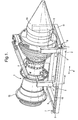
- Fig. 1 illustrates an engine core 1 secured upon a platform 2 in accordance with aspects of the present invention.
- the core 1 takes a conventional form and as will be understood can be associated with a gas turbine engine with compressor fan stages and other parts to constitute a gas turbine engine.
- the platform 2 incorporates a carriage or carrier dolly 3 having upstanding mounting members 4, 5 upon which the core 1 is secured and mounted.
- the carriage dolly 3 is moveable in the direction of arrowheads A along a conveyor path typically defined by rails or other mechanisms. It will be appreciated in Fig. 1 the carriage dolly 3 is at one extremity and therefore can be slid or otherwise moved to the other end 6 of the platform 2.
- bearings 7 are provided along which the dolly carriage 3 can move and end stops 8 are created to prevent further movement of the carriage dolly relative to the platform.
- movement of the carriage dolly is required and advantageously this will be achieved by providing means for driving such movement such as a hand wheel 9 enabling a screw thread drive association between the carriage dolly and the conveyor path to be driven.
- the engine core is held upon the mountings 4, 5 of the carriage dolly such that alternatively at each extremity of location for that dolly 3, upon the platform an end part of the core 1 extends beyond the platform.
- an exhaust cone 10 extends beyond an end 11 of the platform 2 whilst at the other extremity, that is to say with the carriage dolly 3 substantially adjacent to the end 6 of the platform 2, an inlet end 12 of the engine core 1 will extend beyond that platform 2.
- the mountings 4, 5 and their spacing will be chosen such that stability is provided and the centre of gravity retained between the spacing between the mountings 4, 5.
- the platform 2 will be associated with suspender members typically in the form of boot straps which extend down from mountings associated with a pylon to support the engine in use. It will be appreciated that these boot straps and associated crossbars generally provide appropriate presentation of the suspender members for stable manipulation of the core 1 but are of limited weight and size and therefore will be convenient to use as will be described later.
- Fig. 2 provides a schematic end cross section of the stand arrangement depicted in Fig. 1.
- the engine core 1 is again supported by mountings 4 which engage appropriate parts of the core 1.
- the platform 2 incorporates rails 21 within which rollers 22 act to enable the carrier dolly 3 to be moved along the platform 2.
- the carrier dolly 3 is driven by a screw thread using a turn wheel 9 to drive the platform along the screw thread 19 and conveyor path.
- the dolly 3 can be moved fore and aft as required for adjusting engine position. This means of driving dolly 3 movement could also be used to provide locking of dolly 3 position on the platform for transportation purposes.
- screw thread and pins or latches in combination 18 will retain and lock relative position between the platform 2 and dolly 3 along with associated engine 1.
- Alternative mechanisms and locking devices may be used to retain relative position for transportation. It will also be understood that a motorised screw thread or other technique such as displaceable piston mechanism may be utilised for moving the transport dolly in use.
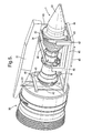
- Fig. 3 illustrates an engine in accordance with aspects of the present invention just prior to removal of the engine core 1 from a fan assembly 30.
- both the engine core 1 and the fan assembly 30 are mounted upon a pylon 31.
- a collar or other form of ground support equipment 32 is provided to support the fan module assembly 30 during an engine core 1 change.
- additional stiffening 33 is provided to support the association between the engine rear fan case and pylon 31 floor to again stabilise the module or assembly 30 during an engine core change. It will be noted that the intake remains attached to the fan case of the engine.
- Fig. 3 illustrates a second stage with regard to removal of the engine core 1 from the fan assembly 30.
- the fan disc curvic coupling and bolts at the base of the structural fan outlet guide vanes are removed to allow core withdrawal.
- Engine fan assembly 30 to engine core 1 systems and couplings are removed and all electrical connections etc., removed to allow detachment of the engine core 1 from the fan assembly 30.
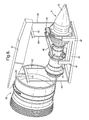
- suspender arms 41, 42 are secured to the pylon 31 with suspender members 43 hanging substantially vertically down to a platform 44 upon which a carriage dolly 45 is presented.
- the carriage dolly 45 includes mounting members 46, 47 with which the engine core 1 can be associated.
- the platform 44 through the carriage dolly 45 generally supports the core 1, although, as will be seen, coupling by mounting 34 and other couplings 46 are also retained at this stage.
- suspender members in the form of boot straps 43 will be individually adjustable to align the platform 44 with an engine axis for easy core 1 removal and withdrawal in view of roll, nose up and toe in core 1 installation attitudes or separate adjustment features could be built into the transportation stand.
- the carriage dolly 45 is able to move in the direction of arrowheads B to disengage a front inlet end of the core 1 from association with the fan assembly 30.
- the dolly 45 traverses from one end of the platform 44 to the other over a translation range dictated by a conveyor path within that platform 44. As indicated previously, this will generally take the form of a rail with rollers such that the dolly carriage 44 is captively retained.
- movement of the transporting carriage 45 may be such that it is driven by a screw thread and head wheel or motor.
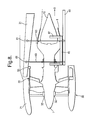
- Fig. 6 illustrates the lowering process. It will be understood that this lowering is achieved principally through extension of the suspender members 43 until the platform 44 engages with the ground or transport pallet. In such circumstances the front mount and fan case systems remain in place as well as the intake fan, fan cowl doors and thrust reverser can be retained although not shown on the drawing for clarity.
- the core 1 and stand comprising the platform 44 and carriage 45 on the ground it will be appreciated it is ready for transportation.
- the position of the core 41 on the platform 44 may be adjusted such that the carriage is more centrally located between the extremities of the conveyor path and locked in position.
- the suspender members 43 and arms 41 and 42 may be removed.
- the platform 44 will normally include anchors (not shown) to allow it to be secured to or within a transport container.
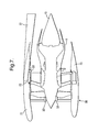
- Fig. 7 provides a side cross section of an engine prior to removal of the engine core in accordance with aspects of the present invention. Similar reference nomenclature has been used to previous drawings for comparison and clarity.
- the fan assembly 30 has retained its intake 71 attached to a fan case.
- ground support equipment 32 in the form of chocks are located between the blade assemblies and the fan casing 71. Whilst these chocks 32 are inserted a further mounting support or stiffener 33 is provided to support the fan case and intake whilst the core 1 is removed against side torque and thrust loads it will be understood that the remaining mountings 72 which secure the engine to the pylon 31 will be retained.
- other parts 73 will be adjusted for access but may remain attached and supported eventually by pylon 31 through appropriate mountings in the engine casing etc.
- Fig. 8 illustrates a situation in side cross section of the engine core 1 prior to removal of an engine core 1.
- panels and other parts of the engine are removed to allow association of a platform 44 supported on suspender members 43 secured at a mounting end 81 to the pylon 71 and at an opposing end to the platform 44.
- a carrier dolly 45 Secured upon a platform 44 is a carrier dolly 45 with which the core 41 is associated. This association may be simply through weight but more normally will be through more robust mountings between the carrier 45 and the core 1.
- the dolly carrier 45 can be moved in the direction of arrowheads B to a position as depicted in Fig. 9.
- the suspender members 34 will generally be adjusted to cause appropriate alignment between the core 1 and the carrier 45 to allow the core 1 to be moved aft of a wing upon which the pylon 31 is secured.
- This extraction of the core 1 from the fan assembly module 30 will generally require a precise axial displacement laterally away from the module 30. Adjustment of the suspender members 43 will ensure that the correct orientation of the conveyor path is achieved.
- the dolly carriage 45 moves along a conveyor path typically formed by rails within the platform 44. These rails therefore defining a translation range for the carrier 45 upon which the core 1 can be moved for detachment from the fan assembly 30.
- the centre of gravity for the core and the combination of the core with the platform 44/carriage 45 should remain within the mountings 41 and 42 of the carriage 45. In such circumstances during detachment the whole assembly will remain stable with the platform 44 secured and suspended through the suspender members 43 to the pylon 31.
- some manoeuvring will be required to clear certain features within the association therebetween.
- This adjustment may be achieved through lowering or lifting the suspender members 34 as required, that is to say extending or shortening them.
- the core when withdrawn from the fan assembly 30 provides greater access for in-situ repairs to be performed on the engine core but more normally an engine core will be lowered to ground level and transported away upon the platform and carriage dolly as described above for repairs etc.
- aspects of the present invention provide an engine core stand arrangement to allow transportation and removal of a core from a gas turbine engine.
- the existing pylon of the engine is utilised with support members in the form of boot straps which extend down to a platform and then through appropriate careful translation of a carriage dolly the core can be removed from association with a fan assembly.
- the stand arrangement is used in accordance with a method whereby initially the fan case and other parts of the gas turbine engine are appropriately chocked and otherwise secured to ensure they remain supported and associated with the pylon when the engine core is removed.
- a platform and carriage dolly will be substantially specific to a particular engine type and mountings with regard to the pylon association.
- the suspender members can take the form of conventional boot straps.
- These boot straps may be cables which can be detached and easily transported along with a cross beams as described previously reducing transportation costs and complexity.
- the present invention is a frame for removing the engine core 1, or a part thereof, of a gas turbine engine which is attached to the pylon or other airframe suspension system.
- the frame comprises a platform 2, 44 with a conveyor path for a dolly carrier 3, 45 to carry an engine core 1 (or part thereof) in use and suspender members 43 for securing the platform to an engine pylon 31.
- the arrangement is characterised by the suspender members 43 having spaced mounting 4, 5 positions and the conveyor path defines a translation range for the dolly carrier to ensure when an engine is secured to the carrier as a combination; that combination has a centre of gravity between a spacing 48 between the mounting positions.
- the core engine, or a part such as a compressor stage may be removed from the engine while the remainder of the engine is still connected to the aircraft. This allows much faster maintenance times that current practise of removing the entire engine.
Landscapes
- Engineering & Computer Science (AREA)
- Mechanical Engineering (AREA)
- Transportation (AREA)
- General Engineering & Computer Science (AREA)
- Chemical & Material Sciences (AREA)
- Combustion & Propulsion (AREA)
- Manufacturing & Machinery (AREA)
- Aviation & Aerospace Engineering (AREA)
- Structures Of Non-Positive Displacement Pumps (AREA)
- Automatic Assembly (AREA)
- Automobile Manufacture Line, Endless Track Vehicle, Trailer (AREA)
Abstract
Description
- The present invention relates to arrangements and methods for removing engine cores from gas turbine engines to facilitate transportation.
- It will be understood that for maintenance, installation and refurbishment it is necessary to transport gas turbine engines. It will also be understood that as fan diameters become larger in order to improve operational efficiency and performance it is necessary to use specialist air freight transport aircraft to move such large diameter gas turbine engines. In such circumstances, increasingly it is desirable to separate the fan and core modules as necessary to allow transportation of larger fan diameter engines as more standard air or road freight. It will also be understood shipping only a replacement core for a gas turbine engine rather than a complete replacement engine will save costs in comparison with holding and transporting a complete spare engine. Finally, it will also be understood that the ability to replace an engine core on wing will save time compared to removing the complete engine and swapping out a replacement core in that removed engine. It is known to provide engine core removal on wing and one method of achieving such removal is described in
US patent number 5860275 . It is also known to remove engines using ground support equipment. Clearly, it is known to provide transportation stands which will allow a fan and core module to be transported together but only once the engine is removed from its wing location. - In view of the above, it will be appreciated that prior art engine core stands and methods of removing engines required the engine core to be shipped on a dedicated transportation stand with a large overhead gantry shipped separately for loading and re-assembly etc. The large overhead gantry was utilised to lift and attach the engine to the aircraft structure. Furthermore, additional features of the engine such as the nacelle reverser may need to be removed to allow rails for removal of the engine to be fitted and it may be difficult to provide a rail for the gantry to match the required withdrawal direction, that is to say to suit all installation attitudes including roll/dihedral, nose up and toe in attitudes.
- In accordance with aspects of the present invention there is provided an engine core removal frame arrangement for a gas turbine engine, the arrangement comprising a platform with a conveyor path for a dolly carrier to carry an engine core in use and suspender members for securing the platform to an engine pylon in use. The arrangement characterised in that the suspender members have spaced mounting positions and the conveyor path defines a translation range for the dolly carrier to ensure when an engine is secured to the carrier as a combination that combination has a centre of gravity between the spacing between the mounting positions.
- Typically, the conveyor path comprises a rail or rails. Additionally, the conveyor path includes rollers to facilitate movement by the dolly carrier along the conveyor path. Possibly, the dolly carrier is captured on the conveyor path. Typically, the dolly carrier comprises a cage to engage and retain an engine core.
- Possibly, the suspender members are arranged to hang vertically towards the platform from cross beams secured in use to a pylon. Generally, the suspender members are adjustable for altering platform and therefore conveyor path position relative to an engine in use. Possibly, the platform has couplings to secure the arrangement to an engine in use by alignment with the conveyor path.
- Possibly, the conveyor path and/or dolly carrier can be driven on the conveyor path. Possibly, the conveyor path and/or dolly carrier can be driven by a driven screw thread or hydraulic piston relative to each other.
- Possibly, the conveyor path and/or dolly carrier have a lock to secure relative location to each other.
- Possibly, weights can be added to the platform in order to alter the centre of gravity of the combination of an engine in use secured upon a platform.
- Typically, the suspender members have an adjustable length in order to allow the platform to be lowered or lifted as required in order to remove the engine.
- Typically, the platform includes means for movement or anchoring in a transport container.
- Also in accordance with aspects of the present invention there is provided a method of removing an engine core from a gas turbine engine, the method comprising exposing an engine core by removal of external panels, the method characterised by attaching an engine core stand arrangement as described above by securing the suspender members to a pylon upon which the engine is mounted, associating the engine with the platform using the dolly carrier, moving the dolly carrier along the conveyor path and lowering the dolly carrier with the engine for appropriate transportation.
- Further in accordance with the present invention there is provided an engine core removal frame for a gas turbine engine, the stand comprising a platform, the frame characterised by defining a conveyor path upon which a dolly carrier is secured by a lock, the dolly carrier including mountings for association with an engine in use and the lock ensuring retention of carrier position relative to the platform upon the conveyor path.
- Embodiments of the present invention will now be described by way of example only and with reference to the accompanying drawings in which:-
- Fig. 1 is a schematic front perspective view of an engine core stand arrangement in accordance with aspects of the present invention associated with an engine core;
- Fig. 2 is a schematic end cross section of an engine stand arrangement in accordance with aspects of the present invention associated with an engine;
- Fig. 3 is a front side perspective view of an engine core associated with a fan unit and a pylon just prior to removal in accordance with a method of the present invention;
- Fig. 4 is a slight rear perspective view of an engine core with engine core stand arrangement in accordance with aspects of the present invention upon initial core removal;
- Fig. 5 is a part rear perspective view of an engine core upon an engine stand arrangement in accordance with aspects of the present invention upon initial withdrawal of the engine core in accordance with a method of the present invention;
- Fig. 6 is a slight rear perspective view of the engine core on the stand arrangement in accordance with aspects of the present invention lowered to ground level;
- Fig. 7 is a schematic side view of an engine core just prior to removal of the engine core in accordance with aspects of the present invention;
- Fig. 8 is a schematic side view of the engine core with stand arrangement in accordance with aspects of the present invention just prior to engine core removal; and,
- Fig. 9 is a schematic view of the engine core removed from association with a fan assembly in accordance with aspects of the present invention.
- As indicated above, ready and convenient transportation of gas turbine engines is desirable. In such circumstances, provision of a gas turbine engine stand arrangement which allows removal of an engine core from the gas turbine engine and also facilitates transportation would be advantageous. Clearly, removal of the engine core will require specialist ground support equipment. This ground support equipment should conveniently be of a minimised size and weight to allow easy transportation.
- In accordance with aspects of the present invention, a gas turbine engine's existing pylon is utilised to enable removal of the core and a boot strap type arrangement utilised in order to facilitate lifting of the engine either out of engagement with the fan or into engagement with the fan unit of a gas turbine engine as required. As will be described later, essentially a platform is provided which is suspended by suspender members, that is to say boot straps secured to the engine platform. The platform includes a dolly carrier to support and engage with the engine core and associated with a conveyor path to allow initially substantially axial movement of the engine core for removal from association with the fan unit of the engine. Once axially moved the platform as well as associated engine can be lowered to a ground level upon removal from the engine or lifted into appropriate position when a replacement engine core is to be associated with the fan unit. The platform also provides a transportation jig for the engine core when the carrier dolly is locked in position upon the platform.
- In terms of ground support equipment it will be understood that all that is required is the boot strap type suspender members which are generally associated through cross beams with the engine pylon to allow removal and chocks for the fan module assembly. In accordance with aspects of the present invention, an engine core can then therefore be removed and transported with less equipment by utilising the existing pylon within the engine mounting on wing.
- In order to maintain stability it will be appreciated that the centre of gravity of the combination of the engine core and platform must be controlled and in such circumstances the carrier dolly will generally comprise a frame having spaced mountings to provide the engine with topple stability and also within the confines of the conveyor path on the platform limited lateral displacement distance or translation range for the engine. Thus, the suspender member locations upon the pylon as well as the centre of gravity are controlled to ensure stability as the engine is removed. The spacing of the mountings of the carrier dolly will therefore define the safe positions for the centre of gravity for the engine core/platform combination on removal and/or installation.
- Fig. 1 illustrates an engine core 1 secured upon a platform 2 in accordance with aspects of the present invention. The core 1 takes a conventional form and as will be understood can be associated with a gas turbine engine with compressor fan stages and other parts to constitute a gas turbine engine.
- The platform 2 incorporates a carriage or
carrier dolly 3 having upstanding mountingmembers 4, 5 upon which the core 1 is secured and mounted. Thecarriage dolly 3 is moveable in the direction of arrowheads A along a conveyor path typically defined by rails or other mechanisms. It will be appreciated in Fig. 1 thecarriage dolly 3 is at one extremity and therefore can be slid or otherwise moved to the other end 6 of the platform 2. Generally, bearings 7 are provided along which thedolly carriage 3 can move andend stops 8 are created to prevent further movement of the carriage dolly relative to the platform. Clearly, movement of the carriage dolly is required and advantageously this will be achieved by providing means for driving such movement such as ahand wheel 9 enabling a screw thread drive association between the carriage dolly and the conveyor path to be driven. It will be noted that generally the engine core is held upon themountings 4, 5 of the carriage dolly such that alternatively at each extremity of location for thatdolly 3, upon the platform an end part of the core 1 extends beyond the platform. In such circumstances in the configuration depicted in Fig. 1 anexhaust cone 10 extends beyond an end 11 of the platform 2 whilst at the other extremity, that is to say with thecarriage dolly 3 substantially adjacent to the end 6 of the platform 2, aninlet end 12 of the engine core 1 will extend beyond that platform 2. In such circumstances, it will be understood that balance is important with regard to the combination of the platform 2 and the core 1 and therefore themountings 4, 5 and their spacing will be chosen such that stability is provided and the centre of gravity retained between the spacing between themountings 4, 5. - In use the platform 2 will be associated with suspender members typically in the form of boot straps which extend down from mountings associated with a pylon to support the engine in use. It will be appreciated that these boot straps and associated crossbars generally provide appropriate presentation of the suspender members for stable manipulation of the core 1 but are of limited weight and size and therefore will be convenient to use as will be described later.
- Fig. 2 provides a schematic end cross section of the stand arrangement depicted in Fig. 1. Thus, similar reference nomenclature has been used for comparison. The engine core 1 is again supported by
mountings 4 which engage appropriate parts of the core 1. The platform 2 incorporatesrails 21 within whichrollers 22 act to enable thecarrier dolly 3 to be moved along the platform 2. As previously, thecarrier dolly 3 is driven by a screw thread using aturn wheel 9 to drive the platform along thescrew thread 19 and conveyor path. In such circumstances, thedolly 3 can be moved fore and aft as required for adjusting engine position. This means of drivingdolly 3 movement could also be used to provide locking ofdolly 3 position on the platform for transportation purposes. In such circumstances the screw thread and pins or latches incombination 18 will retain and lock relative position between the platform 2 anddolly 3 along with associated engine 1. Alternative mechanisms and locking devices may be used to retain relative position for transportation. It will also be understood that a motorised screw thread or other technique such as displaceable piston mechanism may be utilised for moving the transport dolly in use. - Fig. 3 illustrates an engine in accordance with aspects of the present invention just prior to removal of the engine core 1 from a
fan assembly 30. As can be seen, both the engine core 1 and thefan assembly 30 are mounted upon apylon 31. A collar or other form ofground support equipment 32 is provided to support thefan module assembly 30 during an engine core 1 change. Furthermore, additional stiffening 33 is provided to support the association between the engine rear fan case andpylon 31 floor to again stabilise the module orassembly 30 during an engine core change. It will be noted that the intake remains attached to the fan case of the engine. Other mountings are retained to hold the fan case and core in place at this stage and a front fan case engine mount is not disconnected, the fan case to pylon disconnects are not broken but the outer panels and casings of the engine are removed to allow access. In such circumstances, the engine core 1 is secured to thepylon 31 through an appropriate mounting 34 and the arrangement depicted in Fig. 3 is ready for removal of the core 1. - Fig. 3 illustrates a second stage with regard to removal of the engine core 1 from the
fan assembly 30. Thus, the fan disc curvic coupling and bolts at the base of the structural fan outlet guide vanes are removed to allow core withdrawal.Engine fan assembly 30 to engine core 1 systems and couplings are removed and all electrical connections etc., removed to allow detachment of the engine core 1 from thefan assembly 30. - In the above
situation suspender arms pylon 31 withsuspender members 43 hanging substantially vertically down to aplatform 44 upon which acarriage dolly 45 is presented. Such arrangement of thesuspender members 43 ensure these members do not foul the core 1 and provides for stable presentation of theplatform 44. Thus, thecarriage dolly 45 includes mountingmembers fan assembly 30. Theplatform 44 through thecarriage dolly 45 generally supports the core 1, although, as will be seen, coupling by mounting 34 andother couplings 46 are also retained at this stage. - It will be understood at least the suspender members in the form of boot straps 43 will be individually adjustable to align the
platform 44 with an engine axis for easy core 1 removal and withdrawal in view of roll, nose up and toe in core 1 installation attitudes or separate adjustment features could be built into the transportation stand. - Referring to Fig. 4, in order to remove the core 1 it will be understood the
mountings pylon 31 so that the weight of the core 1 is taken by thesuspender members 43 through thearms pylon 31. In such circumstances, thecarriage dolly 45 is able to move in the direction of arrowheads B to disengage a front inlet end of the core 1 from association with thefan assembly 30. Thus thedolly 45 traverses from one end of theplatform 44 to the other over a translation range dictated by a conveyor path within thatplatform 44. As indicated previously, this will generally take the form of a rail with rollers such that thedolly carriage 44 is captively retained. Furthermore, movement of the transportingcarriage 45 may be such that it is driven by a screw thread and head wheel or motor. - To aid alignment and to prevent sway during the initial translation it may be desirable to temporarily latch the
platform line 44 to theengine casing 30. This fixture could then be moved once core withdrawal is complete. - It will be appreciated that as the
carriage 45 translates and moves along theplatform 44 care must be taken to ensure that the engine core remains stable. In such circumstances it will be understood that thearms suspender members 43 provide a robust cage or stand for the engine core anchored upon thepylon 31 which in turn is secured to an air craft. In such circumstances in a first situation as depicted in Fig. 4 thefront end 12 of the core 1 extends beyond theplatform 44 whilst in the alternative extreme anexhaust cone part 10 extends beyond theplatform 44. In either situation, as indicated, the arrangement must be stable so that the centre of gravity for the combination of the core 1 and thecarriage 45/platform 44 should remain within the mountingspacing 48 between the boot straps beams 41, 42. - Once the core 1 has been removed from the
fan assembly 30 it will be lowered to the ground. Fig. 6 illustrates the lowering process. It will be understood that this lowering is achieved principally through extension of thesuspender members 43 until theplatform 44 engages with the ground or transport pallet. In such circumstances the front mount and fan case systems remain in place as well as the intake fan, fan cowl doors and thrust reverser can be retained although not shown on the drawing for clarity. - With the core 1 and stand comprising the
platform 44 andcarriage 45 on the ground it will be appreciated it is ready for transportation. The position of the core 41 on theplatform 44 may be adjusted such that the carriage is more centrally located between the extremities of the conveyor path and locked in position. Thesuspender members 43 andarms platform 44 will normally include anchors (not shown) to allow it to be secured to or within a transport container. - As indicated above, it is important that through the removal process the stand and core in association with other parts such as the
pylon 31, remain stable. Part of that procedure is to ensure that the centre of gravity of the combination of the core 1 andplatform 44/carriage 45 remains within the spacing between thesuspender members pylon 31 until at ground level when, as indicated, thecarriage 41 position to the platform may be adjusted through movement along the conveyor path. Clearly, care must be taken that the additional weight does not over-stress the pylon or other parts of the engine/wing mountings. - Fig. 7 provides a side cross section of an engine prior to removal of the engine core in accordance with aspects of the present invention. Similar reference nomenclature has been used to previous drawings for comparison and clarity. Thus, the
fan assembly 30 has retained itsintake 71 attached to a fan case. In order to support thefan assembly module 30, that is to say fan blades during removal of the engine core 1,ground support equipment 32 in the form of chocks are located between the blade assemblies and thefan casing 71. Whilst thesechocks 32 are inserted a further mounting support orstiffener 33 is provided to support the fan case and intake whilst the core 1 is removed against side torque and thrust loads it will be understood that the remainingmountings 72 which secure the engine to thepylon 31 will be retained. Furthermore,other parts 73 will be adjusted for access but may remain attached and supported eventually bypylon 31 through appropriate mountings in the engine casing etc. - Fig. 8 illustrates a situation in side cross section of the engine core 1 prior to removal of an engine core 1. Thus, as can be seen, panels and other parts of the engine are removed to allow association of a
platform 44 supported onsuspender members 43 secured at a mountingend 81 to thepylon 71 and at an opposing end to theplatform 44. Secured upon aplatform 44 is acarrier dolly 45 with which thecore 41 is associated. This association may be simply through weight but more normally will be through more robust mountings between thecarrier 45 and the core 1. Once secured and all other couplings have been detached or removed as necessary, thedolly carrier 45 can be moved in the direction of arrowheads B to a position as depicted in Fig. 9. However, as indicated above, it will be understood before that stage thesuspender members 34 will generally be adjusted to cause appropriate alignment between the core 1 and thecarrier 45 to allow the core 1 to be moved aft of a wing upon which thepylon 31 is secured. This extraction of the core 1 from thefan assembly module 30 will generally require a precise axial displacement laterally away from themodule 30. Adjustment of thesuspender members 43 will ensure that the correct orientation of the conveyor path is achieved. - It will be understood as described previously that the
dolly carriage 45 moves along a conveyor path typically formed by rails within theplatform 44. These rails therefore defining a translation range for thecarrier 45 upon which the core 1 can be moved for detachment from thefan assembly 30. - It will be noted that the centre of gravity for the core and the combination of the core with the
platform 44/carriage 45 should remain within themountings carriage 45. In such circumstances during detachment the whole assembly will remain stable with theplatform 44 secured and suspended through thesuspender members 43 to thepylon 31. Generally, in order to facilitate removal of the core 1 from thefan assembly 30, it will be understood some manoeuvring will be required to clear certain features within the association therebetween. Thus, for example to may be necessary to initially pull the core substantially rearwards for a certain distance along the main axis of the association between thefan assembly 30 and the core 1 and then lower the core 1 a certain distance before fully translating the core 1 upon thecarriage 45 along the rails of theplatform 44. In such circumstances, it will be understood that clashing between the core 1 and rear parts of the pylon mountings may be avoided. This adjustment may be achieved through lowering or lifting thesuspender members 34 as required, that is to say extending or shortening them. - The core when withdrawn from the
fan assembly 30 provides greater access for in-situ repairs to be performed on the engine core but more normally an engine core will be lowered to ground level and transported away upon the platform and carriage dolly as described above for repairs etc. - It will be appreciated that assembly of a replacement core upon a fan assembly in accordance with aspects of the present invention will be a substantial reversal of the method as described above. Thus, the platform and carriage as a transport stand for the engine core will be transported as required to an appropriate aircraft location for assembly.
- In the above circumstances, aspects of the present invention provide an engine core stand arrangement to allow transportation and removal of a core from a gas turbine engine. Rather than a necessity of providing a large gantry, it will be appreciated that the existing pylon of the engine is utilised with support members in the form of boot straps which extend down to a platform and then through appropriate careful translation of a carriage dolly the core can be removed from association with a fan assembly. The stand arrangement is used in accordance with a method whereby initially the fan case and other parts of the gas turbine engine are appropriately chocked and otherwise secured to ensure they remain supported and associated with the pylon when the engine core is removed. Once the fan casing and other parts of the gas turbine engine are appropriately secured, panels are removed to allow the platform, carriage and suspender members access to the engine core. Mounting ends of the suspender members are associated with the pylon to provide a stable basis for removal of the engine core. Generally, it is necessary to adjust the suspender members to provide alignment of the engine core with the dolly carrier or other parts of the stand. Once this process is completed couplings between the engine core and the fan case and pylon are released and the engine core is then allowed to move with the carriage dolly across a conveyor path formed in the platform. The centre of gravity is retained between the suspender members to ensure stability. Once the engine core is sufficiently displaced from the fan case and other parts of the engine it is lowered to the ground. The suspender members can be removed.
- Normally, a platform and carriage dolly will be substantially specific to a particular engine type and mountings with regard to the pylon association. However, it may be possible to use the same carriage platform and suspender members with different engine types with appropriate adjustment and particularly if the weight distribution within the platform can be adjusted to compensate for different weight distributions and sizes with respect to the engine core altering the position of the centre of gravity of that core to ensure that centre of gravity remains within the spacing between the suspender mountings of a stand.
- One particular advantage of the present invention is that the suspender members can take the form of conventional boot straps. These boot straps may be cables which can be detached and easily transported along with a cross beams as described previously reducing transportation costs and complexity.
- As will be appreciated, once the engine core is removed it is securely located upon the platform through robust locking of the carriage upon the platform. It will be understood that protective covers and boxing may also be used where required.
- Modifications and alterations to the present invention will be understood by those skilled in the art. Thus, for example more than two suspender members may be utilised where required in order to potentially enhance stability and in such circumstances the centre of gravity consideration with regard to the combination of the engine core and the platform will then be retained between the extremities of the outside suspender members in order to maintain stability. As indicated, the platform will generally be held captive on rails to move from one end of the platform to the other in order to facilitate removal of the engine core from the engine on the aircraft wing.
- In summary, the present invention is a frame for removing the engine core 1, or a part thereof, of a gas turbine engine which is attached to the pylon or other airframe suspension system. The frame comprises a
platform 2, 44 with a conveyor path for adolly carrier suspender members 43 for securing the platform to anengine pylon 31. The arrangement is characterised by thesuspender members 43 having spaced mounting 4, 5 positions and the conveyor path defines a translation range for the dolly carrier to ensure when an engine is secured to the carrier as a combination; that combination has a centre of gravity between a spacing 48 between the mounting positions. Advantageously, the core engine, or a part such as a compressor stage, may be removed from the engine while the remainder of the engine is still connected to the aircraft. This allows much faster maintenance times that current practise of removing the entire engine. - Whilst endeavouring in the foregoing specification to draw attention to those features of the invention believed to be of particular importance it should be understood that the Applicant claims protection in respect of any patentable feature or combination of features hereinbefore referred to and/or shown in the drawings whether or not particular emphasis has been placed thereon.
Claims (16)
- An engine core (1) removal frame arrangement for a gas turbine engine, the arrangement comprising a platform (2, 44) with a conveyor path for a dolly carrier (3, 45) to carry an engine core (1) in use and suspender members (43) for securing the platform to an engine pylon (31) in use, the arrangement characterised in that the suspender members (43) have spaced mounting (4, 5) positions and the conveyor path defines a translation range for the dolly carrier to ensure when an engine is secured to the carrier as a combination that combination has a centre of gravity between a spacing (48) between the mounting positions.
- An arrangement as claimed in claim 1 wherein the conveyor path comprises a rail or rails (21).
- An arrangement as claimed in claim 1 or claim 2 wherein the conveyor path includes rollers (22) to facilitate movement by the dolly carrier along the conveyor path.
- An arrangement as claimed in any of claims 1, 2 or 3 wherein the dolly carrier is captured on the conveyor path.
- An arrangement as claimed in any preceding claim 1 wherein the dolly carrier comprises a cage to engage and retain engine core in use.
- An arrangement as claimed in any preceding claim wherein the suspender members are arranged to hang vertically towards the platform from cross beams (41, 42) secured in use to the pylon.
- An arrangement as claimed in any preceding claim wherein the suspender members are adjustable or altering platform and therefore conveyor path position relative to an engine in use.
- An arrangement as claimed in any preceding claim wherein the platform has couplings to secure the arrangement to an engine in use by alignment with the conveyor path.
- An arrangement as claimed in any preceding claim wherein the conveyor path and/or dolly carrier can be driven on the conveyor path.
- An arrangement as claimed in claim 9 wherein the conveyor path and/or dolly carrier can be driven by a driven screw thread or hydraulic piston relative to each other.
- An arrangement as claimed in any preceding claim wherein the conveyor path and/or dolly carrier have a lock (18) to secure relative location to each other.
- An arrangement as claimed in any preceding claim wherein weights can be added to the platform in order to alter the centre of gravity of the combination of an engine in use secured upon a platform.
- An arrangement as claimed in any preceding claim wherein the suspender members have an adjustable length in order to allow the platform to be lowered or lifted as required in order to remove the engine.
- An arrangement as claimed in any preceding claim wherein the platform includes means for movement or anchoring in a transport container.
- A method of removing an engine core from a gas turbine engine, the method comprising exposing an engine core by removal of external panels, the method characterised by attaching an engine core removal frame arrangement as claimed in any of claims 1 to 15 above by securing the suspender members (43) to a pylon (31) upon which the engine is mounted, associating the engine with the platform (2) using the dolly carrier (3, 45), moving the dolly carrier along the conveyor path and lowering the dolly carrier with the engine for appropriate transportation.
- An engine removal frame for a gas turbine engine, the stand comprising a platform (2), the stand characterised by defining a conveyor path (21) upon which a dolly carrier (3, 45) is secured by a lock (18), the dolly carrier including mountings (4, 5; 46, 7) for association with an engine core (1) in use and the lock ensuring retention of carrier position relative to the platform upon the conveyor path.
Applications Claiming Priority (1)
| Application Number | Priority Date | Filing Date | Title |
|---|---|---|---|
| GBGB0613929.9A GB0613929D0 (en) | 2006-07-13 | 2006-07-13 | An engine core stand arrangement and method of removal and transportation of an engine core |
Publications (2)
| Publication Number | Publication Date |
|---|---|
| EP1878662A1 true EP1878662A1 (en) | 2008-01-16 |
| EP1878662B1 EP1878662B1 (en) | 2013-10-02 |
Family
ID=36955587
Family Applications (1)
| Application Number | Title | Priority Date | Filing Date |
|---|---|---|---|
| EP07252404.4A Ceased EP1878662B1 (en) | 2006-07-13 | 2007-06-13 | An engine core stand arrangement and method of removal and transportation of an engine core |
Country Status (5)
| Country | Link |
|---|---|
| US (1) | US7770292B2 (en) |
| EP (1) | EP1878662B1 (en) |
| CN (1) | CN101105150B (en) |
| GB (1) | GB0613929D0 (en) |
| SG (1) | SG139661A1 (en) |
Cited By (9)
| Publication number | Priority date | Publication date | Assignee | Title |
|---|---|---|---|---|
| WO2009135975A3 (en) * | 2008-05-06 | 2010-01-28 | Eads Construcciones Aeronauticas, S.A | Device for removing and installing aircraft components |
| DE102008047779A1 (en) * | 2008-07-23 | 2010-01-28 | Claas Fertigungstechnik Gmbh | Transport and assembly vehicle for a component module |
| EP2537755A2 (en) | 2011-06-22 | 2012-12-26 | Rolls-Royce plc | Mounting assembly |
| CN103056653A (en) * | 2013-01-11 | 2013-04-24 | 沈阳黎明航空发动机(集团)有限责任公司 | Bracket type core machine assembly method |
| EP2602193A1 (en) * | 2011-12-08 | 2013-06-12 | Airbus Opérations SAS | Substitution device for aircraft engine |
| EP2461117A4 (en) * | 2009-07-28 | 2013-08-14 | Abengoa Solar New Tech Sa | Structure for lifting and mounting heliostats and trolley for moving said heliostat |
| EP2949885A1 (en) * | 2014-05-26 | 2015-12-02 | Alstom Technology Ltd | Method and device for mounting and removing of a turbine component |
| EP3450704A1 (en) * | 2017-09-01 | 2019-03-06 | General Electric Company | Turbine bearing maintenance apparatus and method |
| US11506087B2 (en) | 2019-03-29 | 2022-11-22 | Rolls-Royce Plc | Gas turbine engine maintenance stand |
Families Citing this family (55)
| Publication number | Priority date | Publication date | Assignee | Title |
|---|---|---|---|---|
| DE102005052077B4 (en) * | 2005-10-28 | 2016-11-24 | Man Diesel & Turbo Se | Device for the lateral mounting and dismounting of a compressor barrel |
| US9032620B2 (en) * | 2008-12-12 | 2015-05-19 | Nuovo Pignone S.P.A. | Method for moving and aligning heavy device |
| US8621873B2 (en) | 2008-12-29 | 2014-01-07 | Solar Turbines Inc. | Mobile platform system for a gas turbine engine |
| FR2952922B1 (en) * | 2009-11-20 | 2012-05-25 | Snecma | HANDLING ASSEMBLY FOR AN AIRCRAFT ENGINE MODULE |
| FR2952921B1 (en) * | 2009-11-20 | 2012-05-25 | Snecma | TRANSPORT TROLLEY FOR AN AIRCRAFT ENGINE MODULE |
| US8720059B2 (en) * | 2010-04-29 | 2014-05-13 | Spirit Aerosystems, Inc. | Apparatus and method for aircraft engine core exchange |
| US8534638B2 (en) * | 2010-05-06 | 2013-09-17 | Hamilton Sundstrand Corporation | Removable gas turbine engine stand |
| US20120110816A1 (en) * | 2010-11-08 | 2012-05-10 | The Boeing Company | Engine Loading System |
| US8418340B2 (en) * | 2011-01-06 | 2013-04-16 | GM Global Technology Operations LLC | Clamping device for tank assembly |
| US8726477B2 (en) | 2011-02-28 | 2014-05-20 | Pratt & Whitney Canada Corp. | Rotor centralization for turbine engine assembly |
| US9228451B2 (en) | 2011-05-03 | 2016-01-05 | Pratt & Whitney Canada Corp. | Gas turbine engine module adapter to a carrier |
| US9151183B2 (en) | 2011-11-21 | 2015-10-06 | United Technologies Corporation | Retractable exhaust liner segment for gas turbine engines |
| US9316108B2 (en) | 2012-03-05 | 2016-04-19 | General Electric Company | Gas turbine frame stiffening rails |
| US9212607B2 (en) | 2012-07-18 | 2015-12-15 | Spirit Aerosystems, Inc. | Intermediate structure for independently de-mountable propulsion components |
| US9097123B2 (en) | 2012-07-26 | 2015-08-04 | General Electric Company | Method and system for assembling and disassembling turbomachines |
| US8789837B2 (en) * | 2012-09-18 | 2014-07-29 | The Boeing Company | Transport and assembly system and method for composite barrel segments |
| US10160076B2 (en) | 2012-09-18 | 2018-12-25 | The Boeing Company | Edge stabilizing system and method for composite barrel segments |
| KR101482573B1 (en) * | 2013-03-22 | 2015-01-21 | 두산중공업 주식회사 | Supporting device for a gas turbine |
| CA2820064C (en) | 2013-07-04 | 2021-02-09 | Finning International Inc. | Stand for machine components |
| GB2509229A (en) * | 2013-11-19 | 2014-06-25 | Rolls Royce Plc | Gas turbine engine fan stand with hinged rotating frame |
| GB2510229C (en) | 2013-11-19 | 2020-03-04 | Rolls Royce Plc | Method of engine split and reassembly |
| DE102014200760A1 (en) * | 2014-01-17 | 2015-07-23 | Siemens Aktiengesellschaft | Runners swivel system |
| FR3017112B1 (en) * | 2014-02-03 | 2017-09-29 | Snecma | TRANSPORT AND HINGING STRUCTURE FOR TURBOMACHINE |
| US9738391B2 (en) * | 2014-03-10 | 2017-08-22 | United Technologies Corporation | Engine installation system |
| WO2015168637A1 (en) * | 2014-05-02 | 2015-11-05 | Morey Joel T | Aircraft engine stand |
| JP6533043B2 (en) * | 2014-08-25 | 2019-06-19 | 三菱航空機株式会社 | Aircraft engine installation method |
| DE102014219050A1 (en) * | 2014-09-22 | 2016-03-24 | Rolls-Royce Deutschland Ltd & Co Kg | Method and device for machining blade tips of a compressor rotor of a gas turbine |
| GB201418396D0 (en) * | 2014-10-17 | 2014-12-03 | Rolls Royce Plc | Gas turbine engine support structures |
| CN104724300B (en) * | 2015-03-27 | 2016-12-07 | 沈阳飞机工业(集团)有限公司 | Aircraft engine installing vehicle alignment system and localization method thereof |
| WO2017116244A1 (en) * | 2015-12-31 | 2017-07-06 | General Electric Company | Combustor assembly lift systems and methods for using the same to install and remove combustor assemblies |
| CN105644806B (en) * | 2016-01-06 | 2017-12-15 | 湖北航天技术研究院总体设计所 | A kind of Multifunctional flat table apparatus for parking, overturn, transporting for aircraft bay section |
| US10184357B2 (en) * | 2016-02-08 | 2019-01-22 | General Electric Company | Lift device for turbine casing and method to lift the casing |
| US10662816B2 (en) * | 2016-04-12 | 2020-05-26 | General Electric Company | System and method to move turbomachinery |
| FR3050722B1 (en) * | 2016-04-28 | 2021-07-02 | Snecma | PROPULSION KIT FOR FILTERED CRADLE AIRCRAFT |
| US10196199B2 (en) * | 2016-06-01 | 2019-02-05 | General Electric Company | Convertible support structures for shipping large machinery |
| DE102016217980A1 (en) * | 2016-09-20 | 2018-03-22 | Siemens Aktiengesellschaft | Device for installing and removing a component of a gas turbine |
| US10030579B2 (en) * | 2016-09-21 | 2018-07-24 | General Electric Company | Systems and methods for a mobile power plant with improved mobility and reduced trailer count |
| FR3058704B1 (en) * | 2016-11-14 | 2018-11-16 | Safran Aircraft Engines | SLIPPER BIPARTITE CRADLE FOR TURBOPROPULSEUR |
| FR3058987B1 (en) * | 2016-11-24 | 2019-08-02 | Safran Aircraft Engines | ORGAN AND TROLLEY FOR THE REMOVAL, TRANSPORT, AND MAINTENANCE OF A TURBOMACHINE |
| US10040579B1 (en) | 2017-10-27 | 2018-08-07 | Jeffrey L. Henderson | Shipping frame for jet aircraft engine transportation |
| US10697637B2 (en) | 2017-11-22 | 2020-06-30 | General Electric Company | System for oxidant intake |
| BE1026219B1 (en) * | 2018-04-20 | 2019-11-21 | Safran Aero Boosters S.A. | METHOD AND TROLLEY FOR HANDLING A RECTIFIER |
| FR3085156B1 (en) * | 2018-08-24 | 2020-09-11 | Safran Nacelles | ASSEMBLY AND PROCEDURE FOR HANDLING AN AIRCRAFT PROPULSION ASSEMBLY |
| FR3085358B1 (en) * | 2018-08-31 | 2020-09-25 | Safran Nacelles | ASSEMBLY AND PROCEDURE FOR HANDLING AN AIRCRAFT PROPULSION ASSEMBLY |
| GB201817935D0 (en) * | 2018-11-02 | 2018-12-19 | Rolls Royce Plc | Method of replacing a module |
| FR3095492B1 (en) * | 2019-04-26 | 2021-05-07 | Safran Aircraft Engines | TOOL FOR REMOVING A BLOWER DISK FROM A MODULE |
| RU2720056C1 (en) * | 2019-06-05 | 2020-04-23 | Публичное акционерное общество "ОДК-Уфимское моторостроительное производственное объединение" (ПАО "ОДК-УМПО") | Device for transportation and installation of gas turbine engine |
| TR202005987A1 (en) * | 2020-04-15 | 2021-10-21 | Tuerk Hava Yollari Teknik Anonim Sirketi | A CARRIER WITH MOVING FAN BLADE HOLDERS |
| CN111946460B (en) * | 2020-08-10 | 2022-08-05 | 中国人民解放军第五七一九工厂 | Guiding device for assembling fan assembly of aircraft engine and assembling method |
| CN113581621A (en) * | 2021-07-13 | 2021-11-02 | 东风柳州汽车有限公司 | Engine assembly material rack |
| US11247787B1 (en) * | 2021-07-20 | 2022-02-15 | NextGen Aero Support, LLC | Aircraft engine storage frame and system |
| CN114394533B (en) * | 2021-12-21 | 2025-06-03 | 中国联合重型燃气轮机技术有限公司 | Gas turbine inlet cylinder overhaul and transfer system and overhaul and transfer method |
| US12208924B1 (en) * | 2022-12-07 | 2025-01-28 | United States Of America As Represented By The Secretary Of The Air Force | Aircraft engine installation alignment system |
| CN116198830A (en) * | 2023-04-20 | 2023-06-02 | 中国航发航空科技股份有限公司 | A packing box for storage and transportation of aero-engine |
| CN117550086B (en) * | 2023-12-29 | 2025-07-04 | 中国航天空气动力技术研究院 | Reusable device for separating protection cover of unmanned aerial vehicle and using method thereof |
Citations (6)
| Publication number | Priority date | Publication date | Assignee | Title |
|---|---|---|---|---|
| US5383652A (en) | 1992-01-27 | 1995-01-24 | Air New Zealand Limited | Engine mounting and transportation apparatus |
| WO1997019850A1 (en) * | 1995-11-30 | 1997-06-05 | Stanley Aviation Corporation | Shipping frame for fan section of aircraft engine |
| US5860275A (en) | 1996-02-02 | 1999-01-19 | Rolls-Royce Plc | Method of combining ducted fan gas turbine engine modules and aircraft structure |
| US5870824A (en) * | 1995-11-30 | 1999-02-16 | Stanley Aviation Corporation | Method of removing a fan section of a jet engine |
| US6170141B1 (en) * | 1998-09-25 | 2001-01-09 | Stanley Aviation Corporation | Shipping system for jet aircraft engine and method of installing and removing jet aircraft engine |
| GB2394940A (en) * | 2002-10-16 | 2004-05-12 | Dennis Gentle | Cowl removal trolley |
Family Cites Families (6)
| Publication number | Priority date | Publication date | Assignee | Title |
|---|---|---|---|---|
| GB1070883A (en) * | 1965-02-04 | 1967-06-07 | Rolls Royce | Engine handling method and apparatus |
| IT1142775B (en) * | 1981-05-22 | 1986-10-15 | Alitalia Spa | HYDRO-PNEUMATIC POSITIONER FOR THE CHANGE OF WING AIRCRAFT ENGINES TO SIMILAR |
| FR2557541B1 (en) * | 1983-12-29 | 1986-09-19 | Snecma | TURBOMACHINE TRANSPORT CABINET |
| GB8508840D0 (en) * | 1985-04-04 | 1985-05-09 | Short Brothers Ltd | Cargo handling system for aircraft |
| US5575607A (en) * | 1994-11-02 | 1996-11-19 | United Technologies Corporation | Jet engine transport vehicle lift system and a build cell |
| DE10216258B4 (en) | 2001-10-04 | 2004-09-30 | Fürsicht Maschinen GmbH | Engine life |
-
2006
- 2006-07-13 GB GBGB0613929.9A patent/GB0613929D0/en not_active Ceased
-
2007
- 2007-06-13 EP EP07252404.4A patent/EP1878662B1/en not_active Ceased
- 2007-06-14 US US11/812,065 patent/US7770292B2/en active Active
- 2007-07-12 SG SG200705182-4A patent/SG139661A1/en unknown
- 2007-07-13 CN CN200710129163XA patent/CN101105150B/en active Active
Patent Citations (6)
| Publication number | Priority date | Publication date | Assignee | Title |
|---|---|---|---|---|
| US5383652A (en) | 1992-01-27 | 1995-01-24 | Air New Zealand Limited | Engine mounting and transportation apparatus |
| WO1997019850A1 (en) * | 1995-11-30 | 1997-06-05 | Stanley Aviation Corporation | Shipping frame for fan section of aircraft engine |
| US5870824A (en) * | 1995-11-30 | 1999-02-16 | Stanley Aviation Corporation | Method of removing a fan section of a jet engine |
| US5860275A (en) | 1996-02-02 | 1999-01-19 | Rolls-Royce Plc | Method of combining ducted fan gas turbine engine modules and aircraft structure |
| US6170141B1 (en) * | 1998-09-25 | 2001-01-09 | Stanley Aviation Corporation | Shipping system for jet aircraft engine and method of installing and removing jet aircraft engine |
| GB2394940A (en) * | 2002-10-16 | 2004-05-12 | Dennis Gentle | Cowl removal trolley |
Cited By (15)
| Publication number | Priority date | Publication date | Assignee | Title |
|---|---|---|---|---|
| WO2009135975A3 (en) * | 2008-05-06 | 2010-01-28 | Eads Construcciones Aeronauticas, S.A | Device for removing and installing aircraft components |
| DE102008047779A1 (en) * | 2008-07-23 | 2010-01-28 | Claas Fertigungstechnik Gmbh | Transport and assembly vehicle for a component module |
| EP2461117A4 (en) * | 2009-07-28 | 2013-08-14 | Abengoa Solar New Tech Sa | Structure for lifting and mounting heliostats and trolley for moving said heliostat |
| EP2537755A2 (en) | 2011-06-22 | 2012-12-26 | Rolls-Royce plc | Mounting assembly |
| US9090353B2 (en) | 2011-06-22 | 2015-07-28 | Rolls-Royce Plc | Mounting assembly |
| US9915205B2 (en) | 2011-12-08 | 2018-03-13 | Airbus Operations (Sas) | Substitution device for aircraft engine |
| EP2602193A1 (en) * | 2011-12-08 | 2013-06-12 | Airbus Opérations SAS | Substitution device for aircraft engine |
| FR2983836A1 (en) * | 2011-12-08 | 2013-06-14 | Airbus Operations Sas | TOOLS FOR AID FOR THE CONSTRUCTION AND MAINTENANCE OF AIRCRAFT |
| CN103056653A (en) * | 2013-01-11 | 2013-04-24 | 沈阳黎明航空发动机(集团)有限责任公司 | Bracket type core machine assembly method |
| CN103056653B (en) * | 2013-01-11 | 2015-12-02 | 沈阳黎明航空发动机(集团)有限责任公司 | A kind of bracket type core machine assembly method |
| EP2949885A1 (en) * | 2014-05-26 | 2015-12-02 | Alstom Technology Ltd | Method and device for mounting and removing of a turbine component |
| EP3450704A1 (en) * | 2017-09-01 | 2019-03-06 | General Electric Company | Turbine bearing maintenance apparatus and method |
| US10968780B2 (en) | 2017-09-01 | 2021-04-06 | General Electric Company | Turbine bearing maintenance apparatus and method |
| US11572806B2 (en) | 2017-09-01 | 2023-02-07 | General Electric Company | Turbine bearing maintenance apparatus and method |
| US11506087B2 (en) | 2019-03-29 | 2022-11-22 | Rolls-Royce Plc | Gas turbine engine maintenance stand |
Also Published As
| Publication number | Publication date |
|---|---|
| CN101105150A (en) | 2008-01-16 |
| SG139661A1 (en) | 2008-02-29 |
| CN101105150B (en) | 2011-10-05 |
| GB0613929D0 (en) | 2006-08-23 |
| EP1878662B1 (en) | 2013-10-02 |
| HK1117214A1 (en) | 2009-01-09 |
| US7770292B2 (en) | 2010-08-10 |
| US20080011932A1 (en) | 2008-01-17 |
Similar Documents
| Publication | Publication Date | Title |
|---|---|---|
| US7770292B2 (en) | Engine core stand arrangement and method of removal and transportation of an engine core | |
| EP2202156B1 (en) | Method and apparatus for mounting and dismounting an aircraft engine | |
| US11572806B2 (en) | Turbine bearing maintenance apparatus and method | |
| US9249733B2 (en) | Gas turbine engine stand | |
| EP3957834B1 (en) | Assembly and method for installing a bladed rotor on a shaft of a gas turbine engine or removing a bladed rotor from the gas turbine engine | |
| US6292999B1 (en) | Method of installing and removing jet aircraft engine | |
| CA2623758C (en) | Method to mount an aircraft engine on a rigid structure of an engine mount | |
| EP2249031A2 (en) | Apparatus and method for transporting and aligning wind turbine rotor blades | |
| WO1993011037A1 (en) | Method for folding helicopter main rotor blades | |
| CN102312796A (en) | The wind turbine blade that has the operating mechanism attachment hole of combination | |
| US10486819B2 (en) | Method and device for mounting an engine on an aircraft pylon | |
| CN114941606A (en) | Mounting system and method for erecting and mounting a wind turbine tower | |
| CN109466867B (en) | Blade transport and storage rack and blade transport and storage method | |
| US20250136265A1 (en) | Aircraft cargo door actuation system | |
| US2944766A (en) | Aircraft engine installation | |
| US8393598B2 (en) | Method and apparatus for removing and replacing components of an airplane | |
| US11686221B2 (en) | Aircraft engine repair tool and method for removal and installation of a mid turbine frame in an aircraft engine | |
| US12280892B2 (en) | Cradle for an aircraft landing gear assembly | |
| CN203581386U (en) | Rotating mechanism for mounting and maintaining aero-engine | |
| HK1117214B (en) | An engine core stand arrangement and method of removal and transportation of an engine core | |
| EP4074646B1 (en) | Bracket for a hoist for lifting a gas engine assembly and the hoist | |
| EP2873814B1 (en) | Method of axially separating an annular system | |
| CN207117013U (en) | Aircraft distribution panel case dismouting equipment |
Legal Events
| Date | Code | Title | Description |
|---|---|---|---|
| PUAI | Public reference made under article 153(3) epc to a published international application that has entered the european phase |
Free format text: ORIGINAL CODE: 0009012 |
|
| 17P | Request for examination filed |
Effective date: 20071116 |
|
| AK | Designated contracting states |
Kind code of ref document: A1 Designated state(s): AT BE BG CH CY CZ DE DK EE ES FI FR GB GR HU IE IS IT LI LT LU LV MC MT NL PL PT RO SE SI SK TR |
|
| AX | Request for extension of the european patent |
Extension state: AL BA HR MK YU |
|
| 17Q | First examination report despatched |
Effective date: 20080229 |
|
| AKX | Designation fees paid |
Designated state(s): DE FR GB NL |
|
| GRAP | Despatch of communication of intention to grant a patent |
Free format text: ORIGINAL CODE: EPIDOSNIGR1 |
|
| INTG | Intention to grant announced |
Effective date: 20130705 |
|
| GRAS | Grant fee paid |
Free format text: ORIGINAL CODE: EPIDOSNIGR3 |
|
| GRAA | (expected) grant |
Free format text: ORIGINAL CODE: 0009210 |
|
| AK | Designated contracting states |
Kind code of ref document: B1 Designated state(s): DE FR GB NL |
|
| REG | Reference to a national code |
Ref country code: GB Ref legal event code: FG4D |
|
| REG | Reference to a national code |
Ref country code: DE Ref legal event code: R096 Ref document number: 602007033106 Country of ref document: DE Effective date: 20131128 |
|
| REG | Reference to a national code |
Ref country code: NL Ref legal event code: VDEP Effective date: 20131002 |
|
| PG25 | Lapsed in a contracting state [announced via postgrant information from national office to epo] |
Ref country code: NL Free format text: LAPSE BECAUSE OF FAILURE TO SUBMIT A TRANSLATION OF THE DESCRIPTION OR TO PAY THE FEE WITHIN THE PRESCRIBED TIME-LIMIT Effective date: 20131002 |
|
| REG | Reference to a national code |
Ref country code: DE Ref legal event code: R097 Ref document number: 602007033106 Country of ref document: DE |
|
| PLBE | No opposition filed within time limit |
Free format text: ORIGINAL CODE: 0009261 |
|
| STAA | Information on the status of an ep patent application or granted ep patent |
Free format text: STATUS: NO OPPOSITION FILED WITHIN TIME LIMIT |
|
| 26N | No opposition filed |
Effective date: 20140703 |
|
| REG | Reference to a national code |
Ref country code: DE Ref legal event code: R097 Ref document number: 602007033106 Country of ref document: DE Effective date: 20140703 |
|
| REG | Reference to a national code |
Ref country code: FR Ref legal event code: PLFP Year of fee payment: 10 |
|
| REG | Reference to a national code |
Ref country code: FR Ref legal event code: CA Effective date: 20170517 |
|
| REG | Reference to a national code |
Ref country code: FR Ref legal event code: PLFP Year of fee payment: 11 |
|
| REG | Reference to a national code |
Ref country code: FR Ref legal event code: PLFP Year of fee payment: 12 |
|
| PGFP | Annual fee paid to national office [announced via postgrant information from national office to epo] |
Ref country code: FR Payment date: 20190625 Year of fee payment: 13 |
|
| PGFP | Annual fee paid to national office [announced via postgrant information from national office to epo] |
Ref country code: DE Payment date: 20190627 Year of fee payment: 13 Ref country code: GB Payment date: 20190627 Year of fee payment: 13 |
|
| REG | Reference to a national code |
Ref country code: DE Ref legal event code: R119 Ref document number: 602007033106 Country of ref document: DE |
|
| GBPC | Gb: european patent ceased through non-payment of renewal fee |
Effective date: 20200613 |
|
| PG25 | Lapsed in a contracting state [announced via postgrant information from national office to epo] |
Ref country code: GB Free format text: LAPSE BECAUSE OF NON-PAYMENT OF DUE FEES Effective date: 20200613 Ref country code: FR Free format text: LAPSE BECAUSE OF NON-PAYMENT OF DUE FEES Effective date: 20200630 |
|
| PG25 | Lapsed in a contracting state [announced via postgrant information from national office to epo] |
Ref country code: DE Free format text: LAPSE BECAUSE OF NON-PAYMENT OF DUE FEES Effective date: 20210101 |