EP1878656A1 - Hochleistungsfähiges System zum Antrieb von Wasserfahrzeugen - Google Patents
Hochleistungsfähiges System zum Antrieb von Wasserfahrzeugen Download PDFInfo
- Publication number
- EP1878656A1 EP1878656A1 EP07008866A EP07008866A EP1878656A1 EP 1878656 A1 EP1878656 A1 EP 1878656A1 EP 07008866 A EP07008866 A EP 07008866A EP 07008866 A EP07008866 A EP 07008866A EP 1878656 A1 EP1878656 A1 EP 1878656A1
- Authority
- EP
- European Patent Office
- Prior art keywords
- concavity
- impeller
- watercraft
- trailing end
- propulsion system
- Prior art date
- Legal status (The legal status is an assumption and is not a legal conclusion. Google has not performed a legal analysis and makes no representation as to the accuracy of the status listed.)
- Withdrawn
Links
- XLYOFNOQVPJJNP-UHFFFAOYSA-N water Substances O XLYOFNOQVPJJNP-UHFFFAOYSA-N 0.000 claims abstract description 40
- 230000005540 biological transmission Effects 0.000 description 3
- 239000011435 rock Substances 0.000 description 3
- 229910000838 Al alloy Inorganic materials 0.000 description 1
- 230000001133 acceleration Effects 0.000 description 1
- 230000015572 biosynthetic process Effects 0.000 description 1
- 238000010276 construction Methods 0.000 description 1
- 230000003247 decreasing effect Effects 0.000 description 1
- 239000011152 fibreglass Substances 0.000 description 1
- 230000006870 function Effects 0.000 description 1
- 238000009434 installation Methods 0.000 description 1
- 238000002955 isolation Methods 0.000 description 1
- 239000000463 material Substances 0.000 description 1
- 238000000034 method Methods 0.000 description 1
- 239000010935 stainless steel Substances 0.000 description 1
- 229910001220 stainless steel Inorganic materials 0.000 description 1
Images


Classifications
-
- B—PERFORMING OPERATIONS; TRANSPORTING
- B63—SHIPS OR OTHER WATERBORNE VESSELS; RELATED EQUIPMENT
- B63H—MARINE PROPULSION OR STEERING
- B63H5/00—Arrangements on vessels of propulsion elements directly acting on water
- B63H5/07—Arrangements on vessels of propulsion elements directly acting on water of propellers
- B63H5/16—Arrangements on vessels of propulsion elements directly acting on water of propellers characterised by being mounted in recesses; with stationary water-guiding elements; Means to prevent fouling of the propeller, e.g. guards, cages or screens
-
- B—PERFORMING OPERATIONS; TRANSPORTING
- B63—SHIPS OR OTHER WATERBORNE VESSELS; RELATED EQUIPMENT
- B63H—MARINE PROPULSION OR STEERING
- B63H11/00—Marine propulsion by water jets
- B63H11/01—Marine propulsion by water jets having means to prevent foreign material from clogging fluid passage way
-
- B—PERFORMING OPERATIONS; TRANSPORTING
- B63—SHIPS OR OTHER WATERBORNE VESSELS; RELATED EQUIPMENT
- B63H—MARINE PROPULSION OR STEERING
- B63H11/00—Marine propulsion by water jets
- B63H11/02—Marine propulsion by water jets the propulsive medium being ambient water
- B63H11/04—Marine propulsion by water jets the propulsive medium being ambient water by means of pumps
- B63H11/08—Marine propulsion by water jets the propulsive medium being ambient water by means of pumps of rotary type
-
- B—PERFORMING OPERATIONS; TRANSPORTING
- B63—SHIPS OR OTHER WATERBORNE VESSELS; RELATED EQUIPMENT
- B63H—MARINE PROPULSION OR STEERING
- B63H11/00—Marine propulsion by water jets
- B63H11/02—Marine propulsion by water jets the propulsive medium being ambient water
- B63H11/10—Marine propulsion by water jets the propulsive medium being ambient water having means for deflecting jet or influencing cross-section thereof
- B63H11/107—Direction control of propulsive fluid
Definitions
- This invention relates to impeller-driven watercraft having a concavity formed in the hull of the watercraft for accommodating the impeller so that the impeller operates at high efficiency.
- a conventional watercraft equipped with an inboard engine has a downwardly-inclined elongate drive shaft that interconnects the output shaft of the engine and a propeller.
- a water-tight opening is formed in the hull so that the elongate drive shaft can extend therethrough.
- a support strut depends from the bottom of the hull and a housing at the lower end of the strut receives the elongate drive shaft.
- the propeller is positioned on the trailing side of the housing, at the trailing end of the elongate drive shaft.
- An inboard or outboard-mounted rudder trails the propeller.
- Inventors have therefore improved the conventional design by forming a tunnel in the hull, at the stem end thereof, in the form of a concavity, and positioning the aforesaid parts in the tunnel.
- This enables the elongate drive shaft to be positioned in a horizontal plane or nearly in a horizontal plane.
- An example of such a watercraft is disclosed in co-pending U.S. patent application No. 10/855,569 to the present inventor. Further examples are disclosed in U.S. patent No. 3,659,547 to Stuart and in U.K. patent application No. 2,248,433 to Renato Levi Limited.
- This arrangement of parts reduces drag so that the engine operates at higher efficiency.
- the parts in the tunnel are also protected from damage by submerged objects.
- a twin engine watercraft is provided with two tunnels, equidistantly spaced on opposite sides of the longitudinal axis of symmetry of the watercraft.
- An intake grate extends over the mouth of each tunnel to admit water but not debris into the concavity.
- a stator in conjunction with a propeller also increases the efficiency of the propeller.
- a propeller when encircled by a housing having a diameter only slightly greater than the diameter of the propeller, becomes an impeller by definition.
- watercraft having at least one tunnel formed in the hull operate at higher levels of efficiency than watercraft lacking such tunnel or tunnels, there remain a few areas where such watercraft could be improved.
- air can be entrained into the tunnel. Specifically, air flows along the top of the tunnel so that the tunnel is not full of water. The air causes turbulence within the tunnel as it mixes with water as it flows through the impeller. A laminar flow through an impeller is more desirable than a turbulent flow because in a laminar flow, only water flows through the impeller. Thrust is lost when air flows through an impeller.
- Tunnel designs are also known where a nozzle has a diameter that is only about half the diameter of the impeller.
- Such reduced-diameter nozzles are commonly provided in watercraft propulsion systems that harness the power created by the action and reaction characteristics of a jet. This reduces engine efficiency by creating a substantial back pressure.
- the bow of a high-performance boat tends to lift up from the water and the stern thereof tends to enter more deeply into the water at high speeds.
- the inventive structure includes a tunnel that defines a concavity formed in a hull of the watercraft.
- the concavity has a longitudinal axis of symmetry coincident with a longitudinal axis of symmetry of the watercraft.
- the concavity has a trailing end coincident with the transom or trailing edge of the watercraft and has a leading end disposed forwardly of the transom.
- the concavity has a minimum depth at its leading end and a maximum depth at its trailing end.
- An impeller and a stator are mounted in the trailing end of the concavity with the stator disposed in trailing relation to the impeller.
- a first cylindrical housing closely encircles the impeller and a second cylindrical housing closely encircles the stator.
- An engine having an output shaft is positioned forwardly of the concavity.
- An elongate drive shaft extends in a substantially horizontal plane from the output shaft to the impeller or it may be angled downwardly at any angle between zero to five degrees (0-5°).
- a top wall of the concavity or tunnel is sloped at an angle between twenty to thirty degrees (20-30°). This ensures that no air pockets are formed in the cavity along said top wall, even when the watercraft is traveling at high speeds. Water therefore flows through the concavity in a laminar flow.
- the diameters of hubs of the stator and the impeller are respectively about 15-20% of the radii of the stator and the impeller. This design conforms to the typical axial-flow model, so that the flow rate is increased to further enhance the performance of the impeller.
- the stator associated with the impeller also enhances such performance.
- the top wall of the concavity which is provided at two lateral sides thereof with two curved sections respectively integrally connected with two opposite side walls of the concavity, is substantially flat near the leading end of the concavity and gradually increases in curvature toward the trailing end of the-concavity, that is, the flat section between the two curved sections of the top wall gradually diminishes from the leading end of the concavity toward the trailing end of the concavity.
- the top wall of the concavity has substantially a semicircular shape that accommodates the impeller and impeller housing and the stator and stator housing at its trailing end.
- the radius of the concavity at its trailing end is slightly greater than a common radius of said impeller and stator.
- a nozzle is disposed in trailing relation to the stator. It has a radius about 15-20% less than the radius of the concavity so that it presents little back pressure to the engine.
- the combination of the impeller, stator and nozzle is so-called an eductor-jet pump or simply a pump.
- a deflector is positioned in the concavity in leading relation to the impeller. Whereas the top wall of the concavity directs water in the top half of the concavity into the impeller, some of the water in the bottom half of the concavity could flow under the left side and the right side of the impeller because the round shape of the impeller does not conform to the relatively flat shape of the hull of the watercraft.
- the deflector is therefore mounted on part of the intake grate and on the bottom of the impellor housing so that water that would have passed to the left and right of the impeller near its lower half is deflected upwardly and radially inwardly into the space bounded by the cylindrical housing of the impeller.
- An intake grate is disposed in the mouth of the concavity to prevent debris from clogging the impeller. Most of the water flowing through the intake grate encounters no obstacles other than the elongate drive shaft before encountering the impeller. Some of the water encounters the deflector as well but the deflector provides arcuate surfaces that do not abruptly change the direction of water flow. Therefore water flows through the impeller in a laminar flow.
- the elongate drive shaft is disposed in a substantially horizontal plane as aforesaid and is coupled to an output shaft of the engine.
- the concavity has a depth at its trailing end sufficient to accommodate the impeller such that a central hub of the impeller is positioned at an elevation substantially equal to an elevation of an output shaft of the engine.
- the nozzle has a diameter only slightly less than a diameter of the circular housing that circumscribes the impeller. Engine efficiency is therefore improved by a low back pressure presented by the nozzle.
- a rectangular-in-configuration trim adjustable ride plate has a width about one and a half times larger than the diameter of the impeller.
- the ride plate has a leading end fixedly mounted on the bottom of the impeller housing and connected to the intake grate trailing end.
- the middle area of the ride plate is mounted on the nozzle front ring near the stator. It is located under the pump and in trailing relation to the bottom of the tunnel.
- the longitudinal axis of the trim adjustable ride plate is coincident with the longitudinal axis of the hull. Since the leading end of the trim adjustable ride plate is stationary and the trailing end of the trim adjustable ride plate can be adjusted to a downwardly inclined position, the lift caused by the trim adjustable ride plate will lift the stem of the watercraft and lower, accordingly, the bow of the watercraft when the watercraft is in a high-speed motion. Because the concavity provided by the present invention is formed at the stem of the watercraft, which results in decrease in buoyancy of the watercraft, the stem of the watercraft tends to sink deeper in the water, especially when the watercraft is in a high-speed motion. However, this phenomenon can be modified by adjusting the incline of the trim adjustable ride plate of the present invention.
- the incline of the trim adjustable ride plate is adjustable by using a plurality of washers disposed between the ride plate and the nozzle. Reducing the number of washers will raise the trailing end of the trim adjustable ride plate, thereby lowering the stem and raising the bow. To the contrary, increasing the number of washers will lower the trailing end of the trim adjustable ride plate, thereby raising the stem and lowering the bow. In other words, the incline of the trim adjustable ride plate is adjustable by changing the collective thickness of the washers used.
- Fig. 1 is a side elevational view of a prior art direct drive having an inboard rudder
- Fig. 2 is a side elevational view of a prior art V-drive having an outboard rudder
- Fig. 3 is a longitudinal sectional view of a prior art water jet propulsion system
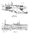
- Fig. 4 is side elevational, diagrammatic view of a marine diesel or gasoline engine having an in-line propulsion system
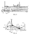
- Fig. 5 is a side elevational, diagrammatic view of an outboard engine head having a ninety degree (90°) propulsion system
- Fig. 6 is a side elevational, enlarged view of the parts depicted in Fig. 4;
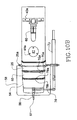
- Fig. 7 is an end sectional view taken along line 7-7 in Fig. 6;
- Fig. 8 is an end sectional view taken along line 8-8 in Fig. 6;
- Fig. 9 is an end view of a twin engine propulsion system
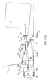
- Fig. 10A is a sectional view taken along line 10 -10 in Fig. 9;
- Fig. 10B is a top view of engine propulsion system;
- Fig 11A a perspective view of the novel structure with the tunnel removed
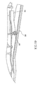
- Fig. 11B is a longitudinal sectional view of the novel apparatus that depicts the trim adjustable ride plate and the means for adjusting its position;
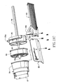
- Fig. 11C is an exploded perspective view of the parts depicted in Figs. 11A and 11B;
- Fig. 12 is a perspective view of the novel tunnel structure
- Fig. 13 is a side elevational view of the tunnel structure
- Fig. 14 is a sectional view taken along the line 14-14 in Fig. 13;
- Fig. 15 is a sectional view taken along the line 15-15 in Fig. 13;
- Fig. 16 is a sectional view taken along the line 16-16 in Fig. 13;
- Fig. 17 is a sectional view taken along the line 17-17 in Fig. 13;
- Fig. 18 is a sectional view taken along the line 18-18 in Fig. 13, and
- Fig. 19 is a partial sectional view showing that the trialing end of the trim adjustable ride plate inclines downwardly.
- a prior art direct drive having an inboard rudder is denoted as a whole by the reference numeral 10 in Fig. 1.
- the assembly of parts includes engine 12, transmission 14, and downwardly-angled elongate drive shaft 16 that extends through a watertight opening formed in hull 18.
- the lower end of drive shaft 16 is rotatably received in cylinder 20 of strut 22 that depends from hull 18.
- Propeller 24 is secured to the distal end of elongate drive shaft 16 for conjoint rotation therewith.
- Inboard rudder 26 is controlled by tiller 28 mounted fore of transom 30.
- elongate drive shaft 16 is thus positioned outside of hull 18 below the surface of the water, together with all of cylinder 20, strut 22, propeller 24 and rudder 26. These parts thus represent drag and lower the efficiency of engine 12. They are also in an exposed, unprotected configuration where they can be damaged by underwater rocks or other substantially immovable submerged objects.
- rudder 26 is mounted aft of transom 30 in this prior art V-drive having an outboard rudder 26.
- the same parts that produce drag in the assembly depicted in Fig. 1 also produce drag in the assembly of Fig. 2.
- FIG. 3 depicts a water jet assembly denoted 32 as a whole.
- Engine 12 and transmission 14 are not depicted in this view, but elongate drive shaft 16 is.
- said elongate drive shaft 16 is horizontally disposed.
- a tunnel defining concavity 34 is formed in hull 18.
- the top wall of concavity 34 is denoted 36 and is angled upwardly relative to said hull at an angle of about forty-five degrees (45°).
- Impeller 38 is mounted to the distal free end of elongate drive shaft 16. Water is drawn into concavity 34 through intake grate 40 at the mouth of said concavity and flows through impeller housing 42 and then through discharge nozzle 44.
- Said discharge nozzle 44 has a diameter that is substantially constricted relative to the diameter of impeller housing 42.
- the velocity of the water therefore must increase in accordance with Bernoulli's principle as it flows through the nozzle and the reactive force caused by such acceleration propels the watercraft forwardly.
- concavity 34 The advantage provided by concavity 34 is that elongate drive shaft 16 is horizontally mounted and thus does not extend below hull 18, thereby reducing drag. Moreover, impeller 38 is also above said hull, and cylinder 20 and strut 22 required to hold the distal end of elongate drive shaft 16 in the first two prior art embodiments discussed above are eliminated, thereby decreasing drag still further. The parts in the concavity are also protected from damage caused by submerged rocks and the like.
- the drawbacks of water jet 32 include the relative inefficiency of the jet propulsion method, attributable at least in part to the back-pressure presented by constricted discharge nozzle 44. Further drawbacks include the turbulent flow of water past impeller 38, caused primarily at high speeds by air pockets that develop in concavity 34.
- This inline system for a marine diesel or gasoline engine includes engine 12, transmission 14, and horizontally-disposed elongate drive shaft 16 having impeller 24 mounted to the distal free end thereof for conjoint rotation therewith.
- Tunnel member 33 is preferably made of the same material as the hull, such as fiberglass reinforced plastic, aluminum alloy, or stainless steel. Tunnel 33 defines concavity 34 and has an interior top wall 36. Said top wall is disposed at a less severe angle than the top wall of prior art concavities.
- Intake grate 40 covers the opening or mouth of concavity 34.
- Non-rotating stator 52 is positioned aft of impeller 24 and aft of transom 30, as are nozzle 54 and rudder 56. However, all of said parts are positioned above hull 18 to minimize drag and to protect them from damage.
- engine includes all types of engines, electric motors, and other sources of power.
- engine shall therefore be construed as including all types of engines, electric motors, and other sources of power.
- Fig. 5 diagrammatically depicts a ninety degree (90°) system having utility in connection with an outboard engine head.
- the ninety degrees (90°) refers to the angle between the vertically disposed output shaft of outboard engine head 12 and horizontally disposed elongate drive shaft 16. This embodiment is depicted to demonstrate the versatility of the novel system.
- Fig. 6 depicts the structure of the Fig. 4 apparatus in greater detail.
- Interior top wall 36 of concavity 34 is inclined at an angle of twenty four degrees (24°) relative to a horizontal plane in this embodiment. However, the range of inclination may be between twenty to thirty degrees (20 - 30°).
- Impeller housing 25 is of cylindrical configuration and circumscribes impeller 24 and stator housing 53, also of cylindrical configuration, circumscribes stator 52.
- Flange 25a circumscribes and extends radially outwardly of impeller housing 25 and is positioned between the leading or fore and trailing or aft ends of said impeller housing.
- the leading end of interior top wall 36 is denoted 36a and the trailing end of said interior top wall is denoted 36b.
- the trailing end of tunnel member 33 is adapted to slidingly ensleeve the leading end of impeller housing 25 and to engage transom 30.
- the trailing end of tunnel 33 therefore has a step formed therein that includes vertical rise 33a and horizontal tread 33b to accommodate flange 25a that circumscribes impeller housing 25.
- the trailing end 36b of top wall 36 has a semicircular configuration, i.e. , it conforms to the shape of the upper half of impeller housing 25. As shown in Figs.
- the top wall 36 defines two symmetrical curved sections 36c at two lateral sides thereof and a flat section between the two curved sections 36c.
- the radius of curvature of the curved sections gradually increases from the leading end 36a of the top wall toward the trailing end 36b of the top wall 36.
- the flat section of the top wall gradually diminishes in width to zero from the leading end 36a of the top wall toward the trailing end 36b of the top wall 36. That is, the trailing end 36b of the top wall has a semicircular crosssection as aforesaid.
- the radius of the top wall at its trailing end is slightly greater than a common radius of the impeller 24 and the stator 52 for enabling the trailing end of the concavity to accommodate the impeller 24 and the stator 25.
- Impeller 24 includes a plurality of blades. The leading edge of said blades is denoted 24a and the trailing edge is denoted 24b. Trailing edge 24b is substantially flush with the trailing end of concavity 34.
- the semicircular upper part 36a of top wall 36 receives the upper half of impeller housing 25 and a semicircular lower wall 37 extends around the lower half of said impeller. Thus, the semicircular top half of top wall 36 and semicircular bottom wall 37 collectively circumscribe impeller housing 25.
- Stator 52 includes a plurality of non-rotating vanes circumscribed by cylindrical housing 53.
- impeller 24 has four (4) rotating blades and stator 52 has eight (8) non-rotating vanes.
- Cone 52a helps maintain a laminar flow of water through stator 52.
- the leading end of nozzle 54 is flanged as is the trailing end of stator housing 53 as aforesaid and the respective flanges are bolted to one another in a well-known way.
- the leading end of stator housing 53 is flanged as at 53a in Fig. 6 and said flange 53a is engaged to the exterior of transom 30 as depicted.
- Nozzle 54 provides a housing for conventional rudder 56. Flap 57 is commercially available and enhances the effectiveness of rudder 56 at slow speeds. Significantly, the diameter of nozzle 54 at its trailing end is almost as great as the diameter of concavity 34 at its greatest diameter. In this embodiment, there is a diminution in diameter of only about five to fifteen percent (5-15%). This reduces the amount of back pressure represented by said nozzle relative to the jet nozzles mentioned above.
- Intake grate 40 is mounted in the opening or mouth of concavity 34. It performs the functions of admitting water into concavity 34 and straining out debris that might foul impeller 24. It is positioned at about a twenty degree (20°) angle relative to horizontal.
- access window 41 If debris gets past intake grate 40 and accumulates to the extent that removal is required, access into concavity 34 is provided by access window 41. Bolts 41 a hold said window in its closed configuration when no access is required.
- Fig. 7 depicts the novel single engine propulsion system in end view before stator 52 is installed and Fig. 8 depicts said system after stator 52 is installed.
- the straight, parallel walls that apparently extend tangentially from semicircular top wall 36 are denoted 39a, 39b. Said parallel walls are the opposing lateral ends of deflector 39, the structure of which is best understood in connection with Figs. 11A and 11B.
- Said deflector as depicted in said Figs. 11A and 11B, is positioned in concavity 34 on the leading side of impeller housing 25 and prevents water from flowing under the left and right sides of impeller housing 25.
- Deflector 39 has arcuate walls that direct the water flowing through concavity 34 to flow through impeller housing 25 without imparting turbulence thereto.
- Fig. 9 depicts a twin engine embodiment, with the right side of the figure depicting the structure before the stator is attached thereto, as in Fig. 7, and the left side of said figure depicting the final installation as in Fig. 8.
- Figs. 10A and 10B differs from the embodiment of Fig. 6 in that elongate drive shaft 16 is inclined downwardly from the engine to impeller 24 at an angle of about five degrees (5°). Additional structural detail is also depicted in Figs. 10A and 10B.
- Stem tube 60 is formed integrally with tunnel 33 and extends therefrom at the same angle at which elongate drive shaft 16 is disposed.
- Cutlass bearing 62 is positioned between the cylindrical inner sidewalls of stem tube 60 and elongate drive shaft 16 so that said elongate drive shaft rotates freely about its axis of rotation within said stem tube 60.
- Lip seal 63 is positioned at the leading end of stem tube 60, and thrust bearing 64 abuts the leading side of said lip seal.
- Stopper 66 is connected to the hull structure of the watercraft and engages the leading end of thrust bearing 64.
- Coupler 68 includes shock-absorbing rubber lining 68a and couples elongate drive shaft 16 to output shaft 70 of engine 12.
- Trim adjustable ride plate 58 also depicted in Figs. 10A and 10B, has a width about fifty percent (50%) greater than the width of impeller 24 as best understood in connection with the top plan view of Fig. 10B.
- Said top plan view also depicts steering hydraulic cylinder 72 and the linkage 74 that interconnects said steering hydraulic cylinder to rudder 56.
- Figs. 10A and 10B also depict transversely disposed mounting bar 40a which is positioned externally to tunnel member 33. The leading ends of the straight members that collectively form intake grate 40 are secured to said mounting bar.
- Fig. 10B best depicts annular interconnecting means 76a formed in the trailing end of impeller housing 25 which is adapted to be secured to corresponding interconnecting means 76b formed in stator housing 53 at a leading end thereof.
- Another interconnecting means 78a is formed in the trailing end of stator housing 53 and is adapted to engage corresponding interconnecting means 78b formed in a leading end of nozzle 54.
- deflector 39 The location and structure of deflector 39 is best understood in connection with Fig. 11A as aforesaid. Tunnel 33 is not depicted so that other parts of the structure are more easily seen. With the exception of deflector 39 and its straight sidewalls 39a, 39b, the parts identified by reference numerals in said Fig. 11A need not be pointed out again.
- Trim adjustable ride plate 58 has a width about fifty percent (50%) greater than the width of impeller 24.
- the ride plate has a leading end fixedly mounted on the bottom of the impeller housing and connected to the intake grate trailing end.
- the middle area of the ride plate is mounted on the nozzle front ring near the stator. It is located under the pump and in trailing relation to the bottom of the tunnel.
- the longitudinal mid-point of trim adjustable ride plate 58 is coincident with the longitudinal axis of symmetry of hull 18. At high speeds, the bow of a watercraft rises relative to the water surface and the stem of said watercraft sinks deeper into the water.
- trim adjustable ride plate 58 is adjusted. Specifically, its trailing end 58b is lowered at high speeds, thereby lifting the stem and lowering the bow to decrease drag.
- the adjustment is accomplished by screws and washers, collectively denoted 59 in Fig. 11B, or by other suitable adjustment means.
- trim adjustable ride plate 58 is adjustable up or down as indicated by double-headed directional arrow 59a in Fig. 11B. As shown in Fig. 19, the more the washers are provided, the lower the trailing end 58b of the trim adjustable ride plate 58 inclines.
- the incline of the trim adjustable ride plate 58 is adjustable by a collective thickness of a plurality of washers disposed between the ride plate and the nozzle.
- the trim adjustable ride plate protects the so-called pump, which is a combination of the impeller, stator and nozzle, from being hit. It also reduces water drag by preventing water from touching the pump parts directly. Thus the water flow is not disturbed so that the current is smooth at the bottom of the trim adjustable ride plate.
- Tunnel member 33 that defines concavity 34 is depicted in isolation in Fig. 12. The parts thereof identified by reference numerals have been disclosed above.
Landscapes
- Chemical & Material Sciences (AREA)
- Engineering & Computer Science (AREA)
- Combustion & Propulsion (AREA)
- Mechanical Engineering (AREA)
- Ocean & Marine Engineering (AREA)
- Structures Of Non-Positive Displacement Pumps (AREA)
- Medicines That Contain Protein Lipid Enzymes And Other Medicines (AREA)
- Cylinder Crankcases Of Internal Combustion Engines (AREA)
Applications Claiming Priority (2)
| Application Number | Priority Date | Filing Date | Title |
|---|---|---|---|
| US80680106P | 2006-07-10 | 2006-07-10 | |
| US11/563,714 US7270583B1 (en) | 2006-07-10 | 2006-11-28 | High efficiency watercraft propulsion system |
Publications (1)
| Publication Number | Publication Date |
|---|---|
| EP1878656A1 true EP1878656A1 (de) | 2008-01-16 |
Family
ID=38481726
Family Applications (1)
| Application Number | Title | Priority Date | Filing Date |
|---|---|---|---|
| EP07008866A Withdrawn EP1878656A1 (de) | 2006-07-10 | 2007-05-02 | Hochleistungsfähiges System zum Antrieb von Wasserfahrzeugen |
Country Status (5)
| Country | Link |
|---|---|
| US (1) | US7270583B1 (de) |
| EP (1) | EP1878656A1 (de) |
| JP (1) | JP2008018927A (de) |
| AU (1) | AU2007201964B2 (de) |
| TW (1) | TW200804133A (de) |
Cited By (2)
| Publication number | Priority date | Publication date | Assignee | Title |
|---|---|---|---|---|
| EP2948366A1 (de) * | 2013-01-28 | 2015-12-02 | Voith Patent GmbH | Schiffsantriebsanordnung |
| JP2017056926A (ja) * | 2015-09-15 | 2017-03-23 | 一夫 有▲吉▼ | プロペラの推進効率を高めて高速化した省エネ船 |
Families Citing this family (11)
| Publication number | Priority date | Publication date | Assignee | Title |
|---|---|---|---|---|
| DE102010048897A1 (de) * | 2010-10-19 | 2012-04-19 | Voith Patent Gmbh | Schiff mit einem Antrieb |
| JP2013043629A (ja) * | 2011-08-22 | 2013-03-04 | Ip Management Services Corp | 船舶用推進器 |
| EP2692628A1 (de) * | 2012-08-03 | 2014-02-05 | SI Co Ltd | Schiff mit einem Kanal für Propeller und Ruder, wobei das Ruder nach vorne orientiert ist |
| FI124117B (fi) * | 2012-09-24 | 2014-03-31 | Alamarin Jet Oy | Vesisuihkuvetolaitteen runko venettä varten, vesisuihkuvetolaite ja sovitelma veneessä |
| US10099763B1 (en) * | 2016-03-10 | 2018-10-16 | Djc Marine Technologies Llc | Antifouling system for water jet intake |
| TWI640454B (zh) * | 2017-09-18 | 2018-11-11 | 般若科技股份有限公司 | Marine propulsion system |
| US11492090B2 (en) | 2018-08-21 | 2022-11-08 | Indmar Products Company, Inc. | Jet pump |
| US10486786B1 (en) * | 2018-08-21 | 2019-11-26 | Indmar Products Company Inc. | Jet pump |
| CN109455285A (zh) * | 2018-11-09 | 2019-03-12 | 中国船舶工业集团公司第七0八研究所 | 一种针对喷水推进装置的加强结构 |
| KR102142219B1 (ko) * | 2019-05-23 | 2020-08-06 | 고호남 | 중소형 선박 |
| USD976961S1 (en) * | 2021-05-24 | 2023-01-31 | Jacob A. McFadden | Hinged intake cover for a boat hull |
Citations (7)
| Publication number | Priority date | Publication date | Assignee | Title |
|---|---|---|---|---|
| GB1189153A (en) * | 1967-04-24 | 1970-04-22 | Hovermarine Ltd | Improvements in or relating to Steering and Propulsion Apparatus for a Marine Craft |
| US4055140A (en) * | 1976-01-15 | 1977-10-25 | Kirchhan James J | Jet drive boat cover |
| GB2344332A (en) * | 1998-12-04 | 2000-06-07 | Barrus E P Ltd | Marine propulsion unit |
| US6213824B1 (en) * | 2000-02-11 | 2001-04-10 | Power Vent Technologies, Inc. | Method for reducing vessel draft |
| WO2002030740A1 (en) * | 2000-10-12 | 2002-04-18 | Noyes Evan L Jr | Boat propulsion system |
| US20040192125A1 (en) * | 2002-10-15 | 2004-09-30 | Bouwe Prakken | Vessel provided with a propeller tunnel |
| US6846210B1 (en) * | 2003-04-02 | 2005-01-25 | Jose Abella | Nozzle drive propulsion for a marine craft |
Family Cites Families (5)
| Publication number | Priority date | Publication date | Assignee | Title |
|---|---|---|---|---|
| US3659547A (en) | 1970-06-01 | 1972-05-02 | Penn Yan Boats Inc | Exhaust system for tunnel stern boat |
| US5123867A (en) * | 1990-05-10 | 1992-06-23 | Stefan Broinowski | Marine jet propulsion unit |
| GB2248433A (en) | 1990-10-03 | 1992-04-08 | Levi Renato Ltd | Surface propeller located aft of transom by distance in the range 35% to 80% of propeller diameter |
| US5700169A (en) * | 1996-09-23 | 1997-12-23 | Brunswick Corporation | Inlet adapter for a personal watercraft |
| US6132269A (en) * | 1999-03-09 | 2000-10-17 | Outboard Marine Corporation | Cantilever jet drive package |
-
2006
- 2006-11-28 US US11/563,714 patent/US7270583B1/en not_active Expired - Fee Related
-
2007
- 2007-03-07 TW TW096107909A patent/TW200804133A/zh unknown
- 2007-05-02 EP EP07008866A patent/EP1878656A1/de not_active Withdrawn
- 2007-05-03 AU AU2007201964A patent/AU2007201964B2/en not_active Expired - Fee Related
- 2007-05-17 JP JP2007131407A patent/JP2008018927A/ja active Pending
Patent Citations (7)
| Publication number | Priority date | Publication date | Assignee | Title |
|---|---|---|---|---|
| GB1189153A (en) * | 1967-04-24 | 1970-04-22 | Hovermarine Ltd | Improvements in or relating to Steering and Propulsion Apparatus for a Marine Craft |
| US4055140A (en) * | 1976-01-15 | 1977-10-25 | Kirchhan James J | Jet drive boat cover |
| GB2344332A (en) * | 1998-12-04 | 2000-06-07 | Barrus E P Ltd | Marine propulsion unit |
| US6213824B1 (en) * | 2000-02-11 | 2001-04-10 | Power Vent Technologies, Inc. | Method for reducing vessel draft |
| WO2002030740A1 (en) * | 2000-10-12 | 2002-04-18 | Noyes Evan L Jr | Boat propulsion system |
| US20040192125A1 (en) * | 2002-10-15 | 2004-09-30 | Bouwe Prakken | Vessel provided with a propeller tunnel |
| US6846210B1 (en) * | 2003-04-02 | 2005-01-25 | Jose Abella | Nozzle drive propulsion for a marine craft |
Cited By (3)
| Publication number | Priority date | Publication date | Assignee | Title |
|---|---|---|---|---|
| EP2948366A1 (de) * | 2013-01-28 | 2015-12-02 | Voith Patent GmbH | Schiffsantriebsanordnung |
| EP2948366B1 (de) * | 2013-01-28 | 2018-10-24 | Voith Patent GmbH | Schiffsantriebsanordnung |
| JP2017056926A (ja) * | 2015-09-15 | 2017-03-23 | 一夫 有▲吉▼ | プロペラの推進効率を高めて高速化した省エネ船 |
Also Published As
| Publication number | Publication date |
|---|---|
| AU2007201964A9 (en) | 2008-01-24 |
| US7270583B1 (en) | 2007-09-18 |
| TW200804133A (en) | 2008-01-16 |
| AU2007201964A1 (en) | 2008-01-24 |
| JP2008018927A (ja) | 2008-01-31 |
| AU2007201964B2 (en) | 2008-10-30 |
Similar Documents
| Publication | Publication Date | Title |
|---|---|---|
| US7270583B1 (en) | High efficiency watercraft propulsion system | |
| US4832642A (en) | Outboard boat propulsion installation | |
| JP2009500234A (ja) | 船舶用の複合ノズル・ベンチュリ・システム | |
| JP2023053982A (ja) | マリンダクトプロペラジェット推進システム | |
| US5848922A (en) | Hydrofoil stabilizer for marine motor | |
| US6010380A (en) | Marine exhaust vented forward of propeller hub | |
| US20110263168A1 (en) | Gaseous fluid vessel propulsion system | |
| US5389021A (en) | Motorboat propeller safety shroud | |
| CN101104439A (zh) | 高效率船艇推进系统 | |
| CN112512916B (zh) | 排气系统 | |
| US7264519B2 (en) | Safe efficient outboard motor assembly | |
| US20090130925A1 (en) | Marine propulsor with inlet fluid inducer | |
| CA2407927A1 (en) | Anti-cavitation tunnel for marine propellers | |
| US9127784B2 (en) | Duct arrangement | |
| KR20180048769A (ko) | 선미 덕트를 가진 선미 형상 및 선박 | |
| CN104812662B (zh) | 船 | |
| US7445532B2 (en) | Safe efficient outboard motor assembly | |
| CN108341021A (zh) | 一种复杂浅水域电动涵道风扇推进m型高速快艇 | |
| US6139379A (en) | Jet propelled watercraft and a simplified low cost drive therefor | |
| US20150266554A1 (en) | Tractor Mode Marine Propulsion | |
| KR20010041029A (ko) | 박용 추진기 | |
| CN112124545A (zh) | 一种可以提升水动力性能的吊舱推进器及其布置结构 | |
| US6224435B1 (en) | Inlet structure for water jet apparatus mounted to boat hull | |
| US9446827B2 (en) | Boat hull construction | |
| US20060223387A1 (en) | Propulsor with inlet fluid inducer |
Legal Events
| Date | Code | Title | Description |
|---|---|---|---|
| PUAI | Public reference made under article 153(3) epc to a published international application that has entered the european phase |
Free format text: ORIGINAL CODE: 0009012 |
|
| AK | Designated contracting states |
Kind code of ref document: A1 Designated state(s): AT BE BG CH CY CZ DE DK EE ES FI FR GB GR HU IE IS IT LI LT LU LV MC MT NL PL PT RO SE SI SK TR |
|
| AX | Request for extension of the european patent |
Extension state: AL BA HR MK YU |
|
| 17P | Request for examination filed |
Effective date: 20080131 |
|
| 17Q | First examination report despatched |
Effective date: 20080306 |
|
| AKX | Designation fees paid |
Designated state(s): AT BE BG CH CY CZ DE DK EE ES FI FR GB GR HU IE IS IT LI LT LU LV MC MT NL PL PT RO SE SI SK TR |
|
| STAA | Information on the status of an ep patent application or granted ep patent |
Free format text: STATUS: THE APPLICATION IS DEEMED TO BE WITHDRAWN |
|
| 18D | Application deemed to be withdrawn |
Effective date: 20080717 |