EP1876940B1 - Oberflächenreinigungsvorrichtung mit flüssigkeitsverteiler - Google Patents
Oberflächenreinigungsvorrichtung mit flüssigkeitsverteiler Download PDFInfo
- Publication number
- EP1876940B1 EP1876940B1 EP06824700.6A EP06824700A EP1876940B1 EP 1876940 B1 EP1876940 B1 EP 1876940B1 EP 06824700 A EP06824700 A EP 06824700A EP 1876940 B1 EP1876940 B1 EP 1876940B1
- Authority
- EP
- European Patent Office
- Prior art keywords
- solution
- handle
- dispensing
- outlet
- cleaning
- Prior art date
- Legal status (The legal status is an assumption and is not a legal conclusion. Google has not performed a legal analysis and makes no representation as to the accuracy of the status listed.)
- Expired - Lifetime
Links
Images

Classifications
-
- A—HUMAN NECESSITIES
- A47—FURNITURE; DOMESTIC ARTICLES OR APPLIANCES; COFFEE MILLS; SPICE MILLS; SUCTION CLEANERS IN GENERAL
- A47L—DOMESTIC WASHING OR CLEANING; SUCTION CLEANERS IN GENERAL
- A47L1/00—Cleaning windows
- A47L1/06—Hand implements
- A47L1/15—Cloths, sponges, pads, or the like, e.g. containing cleaning agents
-
- A—HUMAN NECESSITIES
- A47—FURNITURE; DOMESTIC ARTICLES OR APPLIANCES; COFFEE MILLS; SPICE MILLS; SUCTION CLEANERS IN GENERAL
- A47L—DOMESTIC WASHING OR CLEANING; SUCTION CLEANERS IN GENERAL
- A47L13/00—Implements for cleaning floors, carpets, furniture, walls, or wall coverings
- A47L13/10—Scrubbing; Scouring; Cleaning; Polishing
- A47L13/26—Other cleaning devices with liquid supply arrangements
-
- A—HUMAN NECESSITIES
- A47—FURNITURE; DOMESTIC ARTICLES OR APPLIANCES; COFFEE MILLS; SPICE MILLS; SUCTION CLEANERS IN GENERAL
- A47L—DOMESTIC WASHING OR CLEANING; SUCTION CLEANERS IN GENERAL
- A47L13/00—Implements for cleaning floors, carpets, furniture, walls, or wall coverings
- A47L13/10—Scrubbing; Scouring; Cleaning; Polishing
- A47L13/28—Polishing implements
- A47L13/30—Implements for polishing and waxing or oiling, with dispensers for wax or oil
-
- B—PERFORMING OPERATIONS; TRANSPORTING
- B08—CLEANING
- B08B—CLEANING IN GENERAL; PREVENTION OF FOULING IN GENERAL
- B08B1/00—Cleaning by methods involving the use of tools
- B08B1/10—Cleaning by methods involving the use of tools characterised by the type of cleaning tool
- B08B1/14—Wipes; Absorbent members, e.g. swabs or sponges
-
- B—PERFORMING OPERATIONS; TRANSPORTING
- B08—CLEANING
- B08B—CLEANING IN GENERAL; PREVENTION OF FOULING IN GENERAL
- B08B1/00—Cleaning by methods involving the use of tools
- B08B1/10—Cleaning by methods involving the use of tools characterised by the type of cleaning tool
- B08B1/14—Wipes; Absorbent members, e.g. swabs or sponges
- B08B1/143—Wipes
-
- B—PERFORMING OPERATIONS; TRANSPORTING
- B08—CLEANING
- B08B—CLEANING IN GENERAL; PREVENTION OF FOULING IN GENERAL
- B08B1/00—Cleaning by methods involving the use of tools
- B08B1/40—Cleaning tools with integrated means for dispensing fluids, e.g. water, steam or detergents
-
- B—PERFORMING OPERATIONS; TRANSPORTING
- B05—SPRAYING OR ATOMISING IN GENERAL; APPLYING FLUENT MATERIALS TO SURFACES, IN GENERAL
- B05B—SPRAYING APPARATUS; ATOMISING APPARATUS; NOZZLES
- B05B1/00—Nozzles, spray heads or other outlets, with or without auxiliary devices such as valves, heating means
- B05B1/14—Nozzles, spray heads or other outlets, with or without auxiliary devices such as valves, heating means with multiple outlet openings; with strainers in or outside the outlet opening
- B05B1/16—Nozzles, spray heads or other outlets, with or without auxiliary devices such as valves, heating means with multiple outlet openings; with strainers in or outside the outlet opening having selectively- effective outlets
- B05B1/1627—Nozzles, spray heads or other outlets, with or without auxiliary devices such as valves, heating means with multiple outlet openings; with strainers in or outside the outlet opening having selectively- effective outlets with a selecting mechanism comprising a gate valve, a sliding valve or a cock
- B05B1/1636—Nozzles, spray heads or other outlets, with or without auxiliary devices such as valves, heating means with multiple outlet openings; with strainers in or outside the outlet opening having selectively- effective outlets with a selecting mechanism comprising a gate valve, a sliding valve or a cock by relative rotative movement of the valve elements
Definitions
- the present invention relates to an apparatus for polishing and cleaning surfaces, and more specifically to a device capable of dispensing a polishing and cleaning composition and wiping the composition onto the surface simultaneously.
- Numerous devices have been developed over the years for dispensing a cleaning or polishing solution and simultaneously applying or wiping the solution off of the surface.
- the majority of these devices take the form of a mechanism that selectively dispenses an amount of a cleaning and/or polishing solution into a solution or fluid applying member when an actuator, such as an actuating button is pressed.
- the solution is dispensed directly into the solution applying member, e.g., a sponge, so that the solution disperses throughout the solution applying member for application to the surface.
- the cleaning solution is dispensed into the applying member approximately at the center of the applying member, meaning that a significant amount of the solution must be dispensed into the applying member for the solution to disperse to an applying edge or surface of the applying member.
- the amount of solution required to be dispensed into the applying member sufficiently to wet the applying member to enable the solution to be applied from the member to a surface is greater than the amount of solution that is applied to the surface. This can result in a situation where a large amount of solution that is utilized in wetting the applying member is wasted, as the solution normally evaporates out of the applying member when the device is not in use.
- a bottle including a sponge-like applying member disposed at a dispensing end of the bottle.
- the applying member is selectively connectable with a first fluid conduit leading into the bottle and through which a cleaning solution can be dispensed into the applying member for dispersion through the member and subsequent application to the surface.
- the dispensing end also includes a spray nozzle disposed adjacent the applying member that can be activated by retracting the dispensing end into the bottle and rotating the dispensing end to place the spray nozzle in fluid communication with a second fluid conduit.
- FR-A1-2 735 676 discloses a hand-held device for applying a polishing solution to a surface, comprising a handle and a dispensing mechanism located inside the handle.
- the dispensing mechanism includes a solution inlet and solution outlets and a valve which is connected to the inlet and in fluid communication with the outlets.
- the dispensing mechanism includes a rotatable valve capable of selectively enabling the solution to be dispensed from the device by the actuation of the mechanism through either a spray nozzle disposed on the device or through the dispersion of the solution through the applying member.
- the dispensed solution is provided from a solution reservoir or container that is releasably connectable to the device.
- the container enables the solution to be withdrawn as desired from the container through the use of the dispensing mechanism until the total amount of solution within the container is depleted, at which time the container can be easily disengaged from the device for disposal, and a full replacement container can be secured to the device for continued usage of the device.
- the applying member is releasably engageable with a handle for the device such that the applying member can be replaced as it becomes progressively more soiled after a number of uses.
- the applying member is designed to enable the solution to be quickly and evenly dispersed from the dispensing mechanism through the applying member for even application of the solution to the surface.
- the applying member can also include a movable outer member attached to the applying member opposite the handle that enhances the ability of the applying member in cleaning and polishing the surface on which the device is utilized.
- the device is provided with a simplified construction allowing for easy construction and assembly of the device, including the selective dispensing mechanism and the disposable solution applying member, to greatly reduce the time and cost associated with manufacturing and assembling the device.
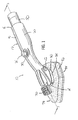
- the polishing and cleaning device constructed according to the present invention is indicated generally at 10 in Fig. 1 .
- the device 10 includes a handle 12 having a forward end 14 and a rearward end 16, and is formed of a pair of opposed halves or sections 18 and 20 connected to one another to form the handle 12.
- the sections 18 and 20 can be formed of any suitable material, but preferably are formed of a rigid, plastic material such that the sections 18 and 20 can be formed in any suitable plastic molding process.
- the sections 18 and 20 can be joined to one another to form the handle 12 utilizing any suitable mechanical structures, such as pins 22 in section 18 that are fixedly received within bores 24 in section 20, any suitable heat-sealing means, or any suitable adhesive means, as well as any combination thereof.
- the handle 12, and sections 18 and 20, can also be formed to have a shape that is easily gripped by an individual, and may also include a separate high-friction coating or rubber (not shown) to improve the ease of use of the device 10.
- the handle 12 includes a depressible button or flexible bulb 26 that forms part of a dispensing mechanism 28 disposed within the handle 12.
- a depressible button or flexible bulb 26 that forms part of a dispensing mechanism 28 disposed within the handle 12.
- other manually activated and mechanically activated dispensing mechanisms can also be employed in the device 10.
- the button 26 is disposed within a recess 30 formed between the opposed sections 18 and 20 of the handle 12 and is operatively connected to a pair of one-way valves 32 and 34 disposed immediately adjacent the button 26.
- the valve 32 allows fluid flow into the space between the button 26 and the valve 32 and is connected to a conduit 36, preferably formed of a flexible, plastic material that extends from the valve 32 rearwardly into connection with a solution inlet 38.
- the inlet 38 is disposed at an inner end 40 of a container housing 42 formed within the rearward end 16 of the handle 12.
- the depth of the housing 42 in the handle 12 is sufficient to enclose the majority of a solution container 50 to prevent the inadvertent disengagement of the container 50 from the handle 12 when the device 10 is in use.
- the housing 42 and container 50 are shown as being generally circular in cross-section, both the housing 42 and container 50 can have any desired shape.
- the housing 42 may include one or more windows (not shown) disposed on the housing 42 to enable an individual to see the amount of cleaning or polishing solution 52 remaining within the container 50.
- An inner end 40 of the housing 42 includes a container engaging member 44 having a sleeve 46 formed therein but directly engages an outlet 48 of the solution container 50.
- the outlet 48 is releasably engaged within the sleeve 46 in a fluid-tight manner which allows a polishing or cleaning solution 52 held within the container 50 to be dispensed through the outlet 48 into the solution inlet 38.
- this is accomplished by forming the outlet 48 with an open end directly engageable with the sleeve 46, or by forming a rupturable plenum (not shown) over the outlet 48 that can be punctured by the solution inlet 38 on engagement of the outlet 48 within the sleeve 46, among other suitable mechanisms, such as a one way valve that opens upon engagement with the container 50.
- the outlet 48 is disengaged from the sleeve 46 such that the entire container 50 can be removed from within the container housing 42 for replacement with a full container 50.
- the second-way valve 34 is also positioned in fluid communication with the button 26 spaced from the one-way valve 32 and allows for fluid flow from the space between the button 28 and valve 34 through the valve 34.
- the valve 34 is connected to a flexible conduit 54, formed similarly to conduit 36, that extends towards the forward end 14 of the handle 12.
- the conduit 54 is engaged opposite the one-way valve 34 with an inlet 56 of a cylindrical housing 58.
- the housing 58 extends between the sections 18 and 20 of the handle 12 and holds a cylindrical, hollow rotatable valve 60 therein.
- the rotatable valve 60 is rotatable within the housing 58 by the operation of a handle 62 extending outwardly from the housing 58 and disposed on the exterior of the handle 12 adjacent section 20 that is engaged with the rotatable valve 60.
- the inlet 56 disposed on the housing 58 is spaced ninety (90) degrees from each of a first outlet 64 and a second outlet 66 that are disposed on the housing 58 directly opposite one another.
- the first outlet 64 is connected to a conduit 68, formed of a flexible material similar to the conduits 36 and 54 described previously, that extends from the first valve outlet 64 to a spray nozzle 70 having nozzle openings 71 extending therethrough that is disposed on the exterior of the forward end 14 of the handle 12.
- the nozzle 70 can have any number of openings 71 and can also be movable to direct the solution 52 where desired.
- the nozzle 70 may also be adjustable to alter the form of the solution 52 being dispensed from the nozzle 70, such as between one or more streams or a fine mist.
- the second outlet 66 is in fluid communication with a conduit 72, formed of a flexible material similar to conduits 36, 54 and 68, described previously, that is connected opposite the second outlet 66 to a fluid dispersion outlet 74.
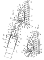
- the rotatable valve 60 includes a pair of apertures 75 spaced ninety (90) degrees from one another. When the valve 60 is rotated using the handle 62, the apertures 75 can be moved between the configuration in Fig. 3 , where the apertures 75 and valve 60 allow fluid to flow from the inlet 56 to the second outlet 66, and the configuration in Fig. 4 , where the apertures 75 and valve 60 allow fluid to flow from the inlet 56 to the first outlet 64.
- the fluid dispersion outlet 74 extends generally downwardly from the handle 12 into a gap 76 formed between the handle 12 and a solution applying member 78.
- the solution applying member 78 is releasably attachable to the handle 12 and includes an attaching member 80 releasably securable to the handle 12, an absorbent member 82 secured to the attaching member 80, and a solution applying and cleaning member 84 attached to the absorbent member 82 opposite the attaching member 80.
- the attaching member 80 can be formed of any suitable and easily releasable mechanism, such as a hook and loop mechanism, or a snap closing, among others.
- the attaching member 80 is formed of a generally rigid material, such as a plastic material, and includes an upwardly extending collar 86 secured to, or integrally formed at one end with a base 88, and having a number of inwardly extending tabs 90 spaced from the base 88.
- the tabs 90 are slidably and releasably engageable within a pair of notches 92 formed adjacent the forward end 14 of each section 18 and 20.
- the tabs 90 are biased into engagement with the notches 92 by the structure of the attaching member 80, which deflects outwardly when initially engaged with the handle 12 into the contact of the tabs 90 with the handle 12. As the attaching member 80 is moved further along the notches 92, the tabs 90 are then urged into each of the notches 92 due to the resiliency of the material forming the attaching member 80 to secure the tabs 90 within the notches 92, and the solution applying member 78 to the handle 12.
- the attaching member 80 also allows the solution applying member 78 to be removed from the forward end 14 of the handle 12 by urging the attaching member 80 away from the notches 92 in order to overcome the bias urging the tabs 90 into the notches 92 and slide the tabs 90 out of the aligned notches 92.
- the base 88 is also formed with a rearwardly extending flange 94 that, when the attaching member 80 is engaged with the forward end 14 of the handle 12, is positioned immediately rearwardly of the forward end 14 to function as an additional securing mechanism for the attaching member 80. Furthermore, the base 88 also includes a central opening 96 that forms the gap 76 between the fluid dispersion outlet 74 and the solution applying member 78 when the attaching member 80 is engaged with the forward end 14 of the handle 12.
- the absorbent member 82 secured to the attaching member 80 can be formed of any suitable, fluid-absorbent material, and preferably an open cell sponge material, such as various natural and synthetic sponge materials, including, but not limited to, cellulosic sponge material and polyurethane open celled foamed material.
- the material forming the absorbent member 82 is capable of retaining the solution 52 dispensed from the container 50 through the device 10 and applying the solution 52 to a surface (not shown) to be polished or cleaned utilizing the solution 52.
- the absorbent member 82 can be utilized alone, or in conjunction with a separate cleaning member 84 releasably attachable to a lower surface 85 of the absorbent member 82 opposite the attaching member 80.
- the cleaning member 84 is formed of a cloth-like material, such as a non-woven cloth, including, but not limited to, composite non-woven cloths formed of cellulosic fibers, rayon fibers, polypropylene fibers and polyester fibers, that is capable of absorbing the solution 52 dispensed from the container 50, and also capable of picking up dust, dirt or other debris on the surface on which the device 10 is being utilized.
- the cleaning member 84 is releasably securable to the absorbent member 82 by any suitable means, such as by a low-tack adhesive, or a hook and loop fastener, among others.
- a secondary cleaning element 98 can be engaged with the solution applying member 78.
- the secondary element 98 can be formed of any suitable cleaning material, such as a mesh or cloth-like material, among others, and includes an endless elastic member 100 secured at one end to define an expandable opening 102 within which the solution applying member 78 can be positioned.
- the elastic member 100 can be expanded to increase the size of the opening 102 to such that the member 78 can be positioned therein, wherein the elastic member 100 is subsequently allowed to contract, thereby engaging the secondary element 98 with the solution applying member 78 around the attaching member 80.
- the cleaning member 84 can be formed as the secondary element 98.
- the container 50 including the solution 52 is engaged within the container housing 42 to provide a supply of the solution 52 to the device 10.
- the valve 60 is rotated within the housing 58 to align the valve apertures 75 with the inlet 56 and either the first outlet 64 for dispensing the solution 52 through the openings 71 in nozzle 70 in front of the solution applying member 78, or with the second outlet 66 for dispensing the solution 52 onto the absorbent member 82.
- the button 26 is then initially depressed to create a vacuum within the button 26, and subsequently released to draw an amount of the solution 52 from the container 50 through the conduit 36 and one-way valve 32 into the button 26.
- a subsequent depressing of the button 26 urges the solution 52 contained in the button 26 through the one-way valve 34 and conduit 54 to the housing 58, while also drawing additional solution from the container 50 into the button 26.
- the solution 52 flows either to the nozzle 70 or to the dispersion outlet 74 for the desired manner of application of the solution 52 to the surface.
Landscapes
- Cleaning Implements For Floors, Carpets, Furniture, Walls, And The Like (AREA)
- Cleaning By Liquid Or Steam (AREA)
- Cleaning Or Drying Semiconductors (AREA)
- Cleaning In General (AREA)
- Containers And Packaging Bodies Having A Special Means To Remove Contents (AREA)
Claims (14)
- Manuelles Gerät (10) zum Reinigen und Polieren einer Oberfläche, wobei das Gerät umfasst:a) einen Griff (12) mit einem rückwärtigen Ende (16) und einem vorderen Ende (14);b) einen innerhalb des Griffs angeordneten Abgabemechanismus (28), wobei der Abgabemechanismus umfasst
einen am rückwärtigen Ende angrenzenden Lösungseinlass (38), einen am vorderen Ende angrenzend angeordneten ersten Lösungsauslass (64) und einen am vorderen Ende angrenzend und beabstandet vom ersten Lösungsauslass angeordneten zweiten Lösungsauslass (66), undc) ein mit dem vorderen Ende des Griffs verbundenes
Lösungsauftragungselement (78) aufweisend eine Verbindung mit dem ersten Lösungsauslass;
gekennzeichnet durch
ein mit dem Lösungseinlass (38) und den ersten und zweiten Lösungsauslässen (64, 66) verbundenes drehbares Ventil (60), wobei
das Lösungsauftragungselement (78) eine Verbindung mit dem ersten Lösungsauslass (64) aufweist. - Gerät gemäß Anspruch 1, wobei das Lösungsauftragungselement (78) ein Absorptionselement (82) aufweist, das zum Auftragen der Lösung auf eine Oberfläche adaptiert ist.
- Gerät gemäß Anspruch 2, wobei der erste Lösungsauslass (64) strömungsmäßig mit dem Absorptionselement (82) verbunden ist.
- Gerät gemäß Anspruch 2, weiter umfassend ein Reinigungselement (84), welches am Absorptionselement (82) befestigt ist.
- Gerät gemäß Anspruch 1, wobei das Lösungsauftragungselement (78) am Griff (12) lösbar befestigt ist.
- Gerät gemäß Anspruch 1, wobei der zweite Lösungsauslass (66) eine Düse (70) umfasst, welche zum Abgeben der Lösung an eine Seite des Lösungsauftragungselements (78) adaptiert ist.
- Gerät gemäß Anspruch 1, weiter umfassend einen lösbar mit dem Lösungseinlass (38) in Eingriff bringbaren Lösungsbehälter (50).
- Gerät gemäß Anspruch 1, wobei der Abgabemechanismus (28) einen zwischen dem Lösungseinlass (38) und dem drehbarem Ventil (60) geschalteten manuellen Aktuator (26) aufweist.
- Verfahren zum Aufbringen einer Reinigungs- oder Polierlösung auf eine Oberfläche, wobei das Verfahren durch folgende Verfahrensschritte gekennzeichnet wird:a) Bereitstellen eines Gerätes (10) umfassend einen Griff (12), einen im Griff angeordneten Abgabemechanismus (28), wobei der Abgabemechanismus einen Lösungseinlass (38), ein betriebsmäßig mit dem Lösungseinlass verbundenes anpassbares Ventil (60) und erste und zweite selektiv mit den Ventil verbundene Lösungsauslässe (64, 66) umfasst;b) Verbinden des Ventils mit einem der ersten oder zweiten Lösungsauslässe;c) in Eingriff bringen eines Lösungsauftragungselement (78) mit dem Griff; undd) Abgeben der Lösung vom Griff durch den Abgabemechanismus.
- Verfahren gemäß Anspruch 9, weiter umfassend den Schritt des in Eingriff bringens eines Lösungsbehälters (50) mit dem Lösungseinlass (38) vor der Abgabe der Lösung.
- Verfahren gemäß Anspruch 10, weiter umfassend die Schritte:a) Entfernen des Lösungsbehälters (50) nach dem Abgeben der Lösung; undb) in Eingriff bringen eines weiteren Behälters mit dem Lösungseinlass (38).
- Verfahren gemäß Anspruch 9, wobei der Schritt des Abgebens einer Lösung das Abgeben einer Lösung durch das Lösungsauftragungselement (78) umfasst.
- Verfahren gemäß Anspruch 9, wobei der Schritt des Abgebens einer Lösung das Abgeben einer Lösung an eine Seite des Lösungsauftragungselements (78) umfasst.
- Verfahren gemäß Anspruch 9, weiter umfassend den Schritt des Anbringens eines Reinigungselements (84) am Lösungsauftragungselement (78) vor dem Abgeben einer Lösung.
Applications Claiming Priority (2)
| Application Number | Priority Date | Filing Date | Title |
|---|---|---|---|
| US11/106,961 US7682097B2 (en) | 2005-04-15 | 2005-04-15 | All-in-one polish dispenser and wiper |
| PCT/US2006/013931 WO2007027207A2 (en) | 2005-04-15 | 2006-04-13 | All-in-one polish dispenser and wiper |
Publications (2)
| Publication Number | Publication Date |
|---|---|
| EP1876940A2 EP1876940A2 (de) | 2008-01-16 |
| EP1876940B1 true EP1876940B1 (de) | 2014-05-14 |
Family
ID=37108611
Family Applications (1)
| Application Number | Title | Priority Date | Filing Date |
|---|---|---|---|
| EP06824700.6A Expired - Lifetime EP1876940B1 (de) | 2005-04-15 | 2006-04-13 | Oberflächenreinigungsvorrichtung mit flüssigkeitsverteiler |
Country Status (7)
| Country | Link |
|---|---|
| US (1) | US7682097B2 (de) |
| EP (1) | EP1876940B1 (de) |
| CN (1) | CN101179975A (de) |
| AU (1) | AU2006285437B2 (de) |
| CA (1) | CA2604535A1 (de) |
| MX (1) | MX2007012858A (de) |
| WO (1) | WO2007027207A2 (de) |
Families Citing this family (34)
| Publication number | Priority date | Publication date | Assignee | Title |
|---|---|---|---|---|
| CA2836948C (en) * | 2004-08-09 | 2015-10-27 | Tyco Healthcare Group Lp | Medical skin applicator apparatus |
| WO2008100747A1 (en) * | 2007-02-09 | 2008-08-21 | Poly-D, Llc | Metering dispensing flexible pouch with spray nozzle |
| WO2008103803A1 (en) | 2007-02-23 | 2008-08-28 | Poly-D, Llc | Surface cleaner with removable wand |
| US20090065607A1 (en) * | 2007-09-10 | 2009-03-12 | Gardner Michael R | Pressure washer system |
| AR076719A1 (es) | 2009-06-02 | 2011-06-29 | Sanofi Aventis Deutschland | Modulo medicinal con derivacion y protector de aguja |
| US20110008096A1 (en) * | 2009-07-13 | 2011-01-13 | Coleman Thomas J | Liquid dispenser |
| US8926210B2 (en) * | 2010-02-04 | 2015-01-06 | Lawrence Orubor | Glass and window cleaning apparatus |
| TWM386054U (en) * | 2010-03-31 | 2010-08-11 | kun-di Huang | Cleaning device |
| CN101947531A (zh) * | 2010-09-26 | 2011-01-19 | 重庆文理学院 | 一种器皿洗涤器及使用方法 |
| US8684619B2 (en) | 2010-10-26 | 2014-04-01 | The Procter & Gamble Company | Cleaning device having plural and customizable cleaning surfaces |
| US9044852B2 (en) | 2010-10-26 | 2015-06-02 | Procter & Gamble | Cleaning device having onboard replaceable cleaning pad and onboard replaceable cleaning solution |
| US20120145189A1 (en) * | 2010-12-08 | 2012-06-14 | Knopow Jeremy F | Portable Self-Heating Steam Generating Device |
| WO2012160529A1 (en) * | 2011-05-24 | 2012-11-29 | Hanan Frum | A motorized handheld polishing and cleaning apparatus |
| USD706786S1 (en) * | 2011-06-13 | 2014-06-10 | TecDriven, LLC | Handle for an electronic device |
| US9212039B1 (en) * | 2011-08-10 | 2015-12-15 | James Reidy | Body scrub brush with liquid soap dispenser |
| US9314146B2 (en) | 2013-02-11 | 2016-04-19 | Gil GAMEIRO | Apparatus for cleaning electronic display surfaces |
| USD720106S1 (en) * | 2013-11-14 | 2014-12-23 | Blue Rhino Global Sourcing, Inc. | Dual handle stone grill cleaner |
| US20150336545A1 (en) * | 2014-02-24 | 2015-11-26 | Anthony Leo Klein | Multi-valet tool |
| US10064535B2 (en) | 2014-10-06 | 2018-09-04 | The Clorox Company | All-in-one scrubbing tool with hook for substrate attachment |
| US10136789B2 (en) | 2014-10-06 | 2018-11-27 | The Clorox Company | All-in-one squeezable scrubbing tool |
| US10071399B2 (en) | 2014-10-06 | 2018-09-11 | The Clorox Company | Article for scrubbing and cleaning hard surfaces and a method for use thereof |
| US9901166B2 (en) * | 2014-12-08 | 2018-02-27 | Joshua Cowan Fifield | Hand pump cleaning brush |
| US10251471B1 (en) | 2015-01-30 | 2019-04-09 | Clint Sanderson | Portable scrubbing and cleaning device with interchangeable brush and cleaning solution cylinder |
| US9901165B2 (en) * | 2015-12-21 | 2018-02-27 | Casabella Holdings, L.L.C. | Dispensing brush |
| US9883785B2 (en) * | 2015-12-21 | 2018-02-06 | Casabella Holdings L.L.C. | Dispensing pad cleaner |
| USD908298S1 (en) | 2016-01-25 | 2021-01-19 | Clint Sanderson | Portable scrubbing and cleaning device with a rounded brush head |
| USD845001S1 (en) * | 2016-02-25 | 2019-04-09 | Turtle Wax, Inc. | Scrub brush |
| WO2017146788A1 (en) | 2016-02-25 | 2017-08-31 | Turtle Wax, Inc. | Spray cap system |
| US10472162B2 (en) | 2016-09-09 | 2019-11-12 | The Clorox Company | Continuous spray dispenser for highly corrosive and other low compatibility products |
| KR102031258B1 (ko) * | 2016-11-01 | 2019-10-11 | 코닌클리케 필립스 엔.브이. | 얼룩 제거 액세서리 |
| USD892614S1 (en) | 2018-06-11 | 2020-08-11 | Ecolab Usa Inc. | Cap for container |
| EP3718642B1 (de) | 2019-02-28 | 2021-12-29 | OP-Hygiene IP GmbH | Umkehrbarer handhaltbarer pumpsprüher |
| US11944186B2 (en) | 2021-03-12 | 2024-04-02 | Burns Brothers LLC | Flexible cleaner |
| US11952756B2 (en) * | 2022-04-06 | 2024-04-09 | Francisco Escobar, III | Water transfer device, and a cleaning implement and a water-dispensing pullout wand of a pulldown faucet formed therewith |
Family Cites Families (34)
| Publication number | Priority date | Publication date | Assignee | Title |
|---|---|---|---|---|
| US1310290A (en) * | 1919-07-15 | Pouktaht-brush | ||
| US1343490A (en) * | 1918-01-24 | 1920-06-15 | Albertson Linden | Valve |
| US1461708A (en) * | 1922-04-03 | 1923-07-10 | Joseph Franchi | Polishing machine |
| US2147769A (en) * | 1937-07-02 | 1939-02-21 | Ralph C Epstein | Cleaning device |
| US2377837A (en) * | 1942-12-03 | 1945-06-05 | William F Zimmermann | Brush applicator |
| US3324855A (en) * | 1965-01-12 | 1967-06-13 | Henry J Heimlich | Surgical sponge stick |
| US3979163A (en) * | 1975-06-16 | 1976-09-07 | Aerosol Techniques Incorporated | Cleaning and scrubbing tool |
| US4078865A (en) * | 1976-09-08 | 1978-03-14 | Moser Robert J | Liquid applicator |
| US4225254A (en) * | 1977-03-17 | 1980-09-30 | Holberg Steven E | Surgical scrub system |
| US4171171A (en) * | 1978-02-07 | 1979-10-16 | Jones Ronald B | Long handled liquid dispensing applicator |
| US4279051A (en) * | 1979-08-15 | 1981-07-21 | Malcolm Elmer L | Combination water spray and rotary brush attachment |
| US4254738A (en) * | 1979-08-27 | 1981-03-10 | Stanley Ada L | No tangle pet brush |
| US4618279A (en) * | 1984-02-15 | 1986-10-21 | Joseph Gurevich | Dishwashing apparatus with plural sponges |
| US4557619A (en) * | 1984-05-22 | 1985-12-10 | Devincentis Cheryl H | Hairbrush and aerosol spray assembly |
| US4776716A (en) * | 1986-03-15 | 1988-10-11 | Sunshine Industries, Inc. | Cleaning device with pivotable head |
| FR2634366B1 (fr) * | 1988-07-25 | 1990-10-12 | Billat Alain | Dispositif de nettoyage a fonctions multiples en particulier pour glaces de vehicules et objets analogues |
| USD352397S (en) * | 1992-10-29 | 1994-11-15 | Harriette Coleman | Medicine applying pet brush |
| US5452961A (en) * | 1994-09-06 | 1995-09-26 | Lu; Tao-Jen | Cleaning apparatus with a cleaning agent dispensing device |
| US5846011A (en) * | 1994-10-07 | 1998-12-08 | Melvin Bernstein | Bottle with built-in telescoping applicator head and spout for applying fluid to a body |
| US5536095A (en) * | 1994-12-07 | 1996-07-16 | Diamond; Peter M. | Squeegee with a pump supplied sponge |
| FR2735676B1 (fr) | 1995-06-20 | 1997-08-01 | Net System | Balai de nettoyage |
| FI956061L (fi) * | 1995-12-15 | 1997-06-16 | Puurunen Juha Pekka | Pumppuhammasharja |
| US5702194A (en) * | 1996-07-08 | 1997-12-30 | Hsu; Shih Hsiung | Cleaner |
| US6065890A (en) * | 1997-03-03 | 2000-05-23 | Weitz; Gene C. | Cleaning apparatus providing coincidental washing and wiping in a synchronized manner |
| US5927290A (en) * | 1997-03-21 | 1999-07-27 | Thiruppathi; Devaraj | Liquid dispensing hair brush |
| US5934296A (en) * | 1997-06-27 | 1999-08-10 | Clay; Julie E. | Liquid applicator |
| US5961235A (en) * | 1998-03-05 | 1999-10-05 | Kennedy; Patricia T. | Lotion applicator with handle reservoir |
| US6010268A (en) * | 1998-12-15 | 2000-01-04 | Prolong Super Lubricants, Inc. | Sponge applicator device |
| US6171004B1 (en) * | 1999-05-03 | 2001-01-09 | Jennifer Derhammer | Cleaning apparatus |
| US6425701B1 (en) * | 2000-02-23 | 2002-07-30 | Rubbermaid Incorporated | Liquid dispensing handle |
| US6805682B1 (en) * | 2002-05-03 | 2004-10-19 | Mark C. Campbell | Fluid applicator |
| US6746166B1 (en) * | 2003-05-02 | 2004-06-08 | Art Center College Of Design | Apparatus for cleaning a surface |
| US6817801B1 (en) * | 2003-05-14 | 2004-11-16 | The Valvoline Company, A Division Of Ashland, Inc. | Automotive interior liquid applicator |
| GB2414654A (en) | 2004-06-04 | 2005-12-07 | Reckitt Benckiser Inc | Hand held wiper with cleaning agent dispensing facility |
-
2005
- 2005-04-15 US US11/106,961 patent/US7682097B2/en active Active
-
2006
- 2006-04-13 MX MX2007012858A patent/MX2007012858A/es active IP Right Grant
- 2006-04-13 EP EP06824700.6A patent/EP1876940B1/de not_active Expired - Lifetime
- 2006-04-13 WO PCT/US2006/013931 patent/WO2007027207A2/en not_active Ceased
- 2006-04-13 AU AU2006285437A patent/AU2006285437B2/en not_active Ceased
- 2006-04-13 CN CNA2006800176873A patent/CN101179975A/zh active Pending
- 2006-04-13 CA CA002604535A patent/CA2604535A1/en not_active Abandoned
Also Published As
| Publication number | Publication date |
|---|---|
| MX2007012858A (es) | 2008-01-11 |
| AU2006285437A8 (en) | 2007-03-08 |
| US7682097B2 (en) | 2010-03-23 |
| WO2007027207A3 (en) | 2007-04-19 |
| CA2604535A1 (en) | 2007-03-08 |
| EP1876940A2 (de) | 2008-01-16 |
| AU2006285437A1 (en) | 2007-03-08 |
| WO2007027207A2 (en) | 2007-03-08 |
| US20060233592A1 (en) | 2006-10-19 |
| AU2006285437B2 (en) | 2011-06-16 |
| CN101179975A (zh) | 2008-05-14 |
Similar Documents
| Publication | Publication Date | Title |
|---|---|---|
| EP1876940B1 (de) | Oberflächenreinigungsvorrichtung mit flüssigkeitsverteiler | |
| US7004658B2 (en) | Fluid valve and actuator for inverted fluid reservoir | |
| US7048458B2 (en) | Fluid valve and actuator for inverted fluid reservoir | |
| AU2001245978B2 (en) | Advanced cleaning system | |
| US6986618B2 (en) | Advanced cleaning system | |
| EP2330962B1 (de) | Reinigungsgerät mit mehreren düsen | |
| AU2001245978A1 (en) | Advanced cleaning system | |
| US20060280546A1 (en) | Apparatus for dispensing liquid | |
| CA2632749C (en) | Cleaning tool | |
| US20180028039A1 (en) | Liquid dispensing cleaning system and methods of use | |
| US20030197027A1 (en) | Mop handle assembly adapted to dispense liquid | |
| CA2484278C (en) | Advanced cleaning system | |
| KR20040017570A (ko) | 바닥청소용 대걸레 |
Legal Events
| Date | Code | Title | Description |
|---|---|---|---|
| PUAI | Public reference made under article 153(3) epc to a published international application that has entered the european phase |
Free format text: ORIGINAL CODE: 0009012 |
|
| 17P | Request for examination filed |
Effective date: 20071015 |
|
| AK | Designated contracting states |
Kind code of ref document: A2 Designated state(s): AT BE BG CH CY CZ DE DK EE ES FI FR GB GR HU IE IS IT LI LT LU LV MC NL PL PT RO SE SI SK TR |
|
| DAX | Request for extension of the european patent (deleted) | ||
| GRAP | Despatch of communication of intention to grant a patent |
Free format text: ORIGINAL CODE: EPIDOSNIGR1 |
|
| INTG | Intention to grant announced |
Effective date: 20131125 |
|
| GRAS | Grant fee paid |
Free format text: ORIGINAL CODE: EPIDOSNIGR3 |
|
| GRAA | (expected) grant |
Free format text: ORIGINAL CODE: 0009210 |
|
| AK | Designated contracting states |
Kind code of ref document: B1 Designated state(s): AT BE BG CH CY CZ DE DK EE ES FI FR GB GR HU IE IS IT LI LT LU LV MC NL PL PT RO SE SI SK TR |
|
| REG | Reference to a national code |
Ref country code: GB Ref legal event code: FG4D |
|
| REG | Reference to a national code |
Ref country code: AT Ref legal event code: REF Ref document number: 667608 Country of ref document: AT Kind code of ref document: T Effective date: 20140615 |
|
| REG | Reference to a national code |
Ref country code: IE Ref legal event code: FG4D |
|
| REG | Reference to a national code |
Ref country code: DE Ref legal event code: R096 Ref document number: 602006041614 Country of ref document: DE Effective date: 20140626 |
|
| REG | Reference to a national code |
Ref country code: AT Ref legal event code: MK05 Ref document number: 667608 Country of ref document: AT Kind code of ref document: T Effective date: 20140514 Ref country code: NL Ref legal event code: VDEP Effective date: 20140514 |
|
| REG | Reference to a national code |
Ref country code: LT Ref legal event code: MG4D |
|
| PG25 | Lapsed in a contracting state [announced via postgrant information from national office to epo] |
Ref country code: FI Free format text: LAPSE BECAUSE OF FAILURE TO SUBMIT A TRANSLATION OF THE DESCRIPTION OR TO PAY THE FEE WITHIN THE PRESCRIBED TIME-LIMIT Effective date: 20140514 Ref country code: LT Free format text: LAPSE BECAUSE OF FAILURE TO SUBMIT A TRANSLATION OF THE DESCRIPTION OR TO PAY THE FEE WITHIN THE PRESCRIBED TIME-LIMIT Effective date: 20140514 Ref country code: CY Free format text: LAPSE BECAUSE OF FAILURE TO SUBMIT A TRANSLATION OF THE DESCRIPTION OR TO PAY THE FEE WITHIN THE PRESCRIBED TIME-LIMIT Effective date: 20140514 Ref country code: IS Free format text: LAPSE BECAUSE OF FAILURE TO SUBMIT A TRANSLATION OF THE DESCRIPTION OR TO PAY THE FEE WITHIN THE PRESCRIBED TIME-LIMIT Effective date: 20140914 Ref country code: GR Free format text: LAPSE BECAUSE OF FAILURE TO SUBMIT A TRANSLATION OF THE DESCRIPTION OR TO PAY THE FEE WITHIN THE PRESCRIBED TIME-LIMIT Effective date: 20140815 |
|
| PG25 | Lapsed in a contracting state [announced via postgrant information from national office to epo] |
Ref country code: ES Free format text: LAPSE BECAUSE OF FAILURE TO SUBMIT A TRANSLATION OF THE DESCRIPTION OR TO PAY THE FEE WITHIN THE PRESCRIBED TIME-LIMIT Effective date: 20140514 Ref country code: AT Free format text: LAPSE BECAUSE OF FAILURE TO SUBMIT A TRANSLATION OF THE DESCRIPTION OR TO PAY THE FEE WITHIN THE PRESCRIBED TIME-LIMIT Effective date: 20140514 Ref country code: LV Free format text: LAPSE BECAUSE OF FAILURE TO SUBMIT A TRANSLATION OF THE DESCRIPTION OR TO PAY THE FEE WITHIN THE PRESCRIBED TIME-LIMIT Effective date: 20140514 Ref country code: SE Free format text: LAPSE BECAUSE OF FAILURE TO SUBMIT A TRANSLATION OF THE DESCRIPTION OR TO PAY THE FEE WITHIN THE PRESCRIBED TIME-LIMIT Effective date: 20140514 Ref country code: PL Free format text: LAPSE BECAUSE OF FAILURE TO SUBMIT A TRANSLATION OF THE DESCRIPTION OR TO PAY THE FEE WITHIN THE PRESCRIBED TIME-LIMIT Effective date: 20140514 |
|
| PG25 | Lapsed in a contracting state [announced via postgrant information from national office to epo] |
Ref country code: PT Free format text: LAPSE BECAUSE OF FAILURE TO SUBMIT A TRANSLATION OF THE DESCRIPTION OR TO PAY THE FEE WITHIN THE PRESCRIBED TIME-LIMIT Effective date: 20140915 |
|
| PG25 | Lapsed in a contracting state [announced via postgrant information from national office to epo] |
Ref country code: CZ Free format text: LAPSE BECAUSE OF FAILURE TO SUBMIT A TRANSLATION OF THE DESCRIPTION OR TO PAY THE FEE WITHIN THE PRESCRIBED TIME-LIMIT Effective date: 20140514 Ref country code: BE Free format text: LAPSE BECAUSE OF FAILURE TO SUBMIT A TRANSLATION OF THE DESCRIPTION OR TO PAY THE FEE WITHIN THE PRESCRIBED TIME-LIMIT Effective date: 20140514 Ref country code: RO Free format text: LAPSE BECAUSE OF FAILURE TO SUBMIT A TRANSLATION OF THE DESCRIPTION OR TO PAY THE FEE WITHIN THE PRESCRIBED TIME-LIMIT Effective date: 20140514 Ref country code: DK Free format text: LAPSE BECAUSE OF FAILURE TO SUBMIT A TRANSLATION OF THE DESCRIPTION OR TO PAY THE FEE WITHIN THE PRESCRIBED TIME-LIMIT Effective date: 20140514 Ref country code: EE Free format text: LAPSE BECAUSE OF FAILURE TO SUBMIT A TRANSLATION OF THE DESCRIPTION OR TO PAY THE FEE WITHIN THE PRESCRIBED TIME-LIMIT Effective date: 20140514 Ref country code: SK Free format text: LAPSE BECAUSE OF FAILURE TO SUBMIT A TRANSLATION OF THE DESCRIPTION OR TO PAY THE FEE WITHIN THE PRESCRIBED TIME-LIMIT Effective date: 20140514 |
|
| REG | Reference to a national code |
Ref country code: DE Ref legal event code: R097 Ref document number: 602006041614 Country of ref document: DE |
|
| PG25 | Lapsed in a contracting state [announced via postgrant information from national office to epo] |
Ref country code: NL Free format text: LAPSE BECAUSE OF FAILURE TO SUBMIT A TRANSLATION OF THE DESCRIPTION OR TO PAY THE FEE WITHIN THE PRESCRIBED TIME-LIMIT Effective date: 20140514 |
|
| PLBE | No opposition filed within time limit |
Free format text: ORIGINAL CODE: 0009261 |
|
| STAA | Information on the status of an ep patent application or granted ep patent |
Free format text: STATUS: NO OPPOSITION FILED WITHIN TIME LIMIT |
|
| 26N | No opposition filed |
Effective date: 20150217 |
|
| REG | Reference to a national code |
Ref country code: DE Ref legal event code: R097 Ref document number: 602006041614 Country of ref document: DE Effective date: 20150217 |
|
| PG25 | Lapsed in a contracting state [announced via postgrant information from national office to epo] |
Ref country code: SI Free format text: LAPSE BECAUSE OF FAILURE TO SUBMIT A TRANSLATION OF THE DESCRIPTION OR TO PAY THE FEE WITHIN THE PRESCRIBED TIME-LIMIT Effective date: 20140514 |
|
| PG25 | Lapsed in a contracting state [announced via postgrant information from national office to epo] |
Ref country code: LU Free format text: LAPSE BECAUSE OF FAILURE TO SUBMIT A TRANSLATION OF THE DESCRIPTION OR TO PAY THE FEE WITHIN THE PRESCRIBED TIME-LIMIT Effective date: 20150413 Ref country code: MC Free format text: LAPSE BECAUSE OF FAILURE TO SUBMIT A TRANSLATION OF THE DESCRIPTION OR TO PAY THE FEE WITHIN THE PRESCRIBED TIME-LIMIT Effective date: 20140514 |
|
| REG | Reference to a national code |
Ref country code: CH Ref legal event code: PL |
|
| REG | Reference to a national code |
Ref country code: IE Ref legal event code: MM4A |
|
| PG25 | Lapsed in a contracting state [announced via postgrant information from national office to epo] |
Ref country code: LI Free format text: LAPSE BECAUSE OF NON-PAYMENT OF DUE FEES Effective date: 20150430 Ref country code: CH Free format text: LAPSE BECAUSE OF NON-PAYMENT OF DUE FEES Effective date: 20150430 |
|
| REG | Reference to a national code |
Ref country code: FR Ref legal event code: PLFP Year of fee payment: 11 |
|
| PG25 | Lapsed in a contracting state [announced via postgrant information from national office to epo] |
Ref country code: IE Free format text: LAPSE BECAUSE OF NON-PAYMENT OF DUE FEES Effective date: 20150413 |
|
| REG | Reference to a national code |
Ref country code: FR Ref legal event code: PLFP Year of fee payment: 12 |
|
| PG25 | Lapsed in a contracting state [announced via postgrant information from national office to epo] |
Ref country code: BG Free format text: LAPSE BECAUSE OF FAILURE TO SUBMIT A TRANSLATION OF THE DESCRIPTION OR TO PAY THE FEE WITHIN THE PRESCRIBED TIME-LIMIT Effective date: 20140514 Ref country code: HU Free format text: LAPSE BECAUSE OF FAILURE TO SUBMIT A TRANSLATION OF THE DESCRIPTION OR TO PAY THE FEE WITHIN THE PRESCRIBED TIME-LIMIT; INVALID AB INITIO Effective date: 20060413 |
|
| PG25 | Lapsed in a contracting state [announced via postgrant information from national office to epo] |
Ref country code: TR Free format text: LAPSE BECAUSE OF FAILURE TO SUBMIT A TRANSLATION OF THE DESCRIPTION OR TO PAY THE FEE WITHIN THE PRESCRIBED TIME-LIMIT Effective date: 20140514 |
|
| REG | Reference to a national code |
Ref country code: FR Ref legal event code: PLFP Year of fee payment: 13 |
|
| PGFP | Annual fee paid to national office [announced via postgrant information from national office to epo] |
Ref country code: IT Payment date: 20180326 Year of fee payment: 13 |
|
| PG25 | Lapsed in a contracting state [announced via postgrant information from national office to epo] |
Ref country code: IT Free format text: LAPSE BECAUSE OF NON-PAYMENT OF DUE FEES Effective date: 20190413 |
|
| PGFP | Annual fee paid to national office [announced via postgrant information from national office to epo] |
Ref country code: FR Payment date: 20230321 Year of fee payment: 18 |
|
| PGFP | Annual fee paid to national office [announced via postgrant information from national office to epo] |
Ref country code: GB Payment date: 20230322 Year of fee payment: 18 |
|
| REG | Reference to a national code |
Ref country code: DE Ref legal event code: R082 Ref document number: 602006041614 Country of ref document: DE Representative=s name: MEISSNER BOLTE PATENTANWAELTE RECHTSANWAELTE P, DE |
|
| P01 | Opt-out of the competence of the unified patent court (upc) registered |
Effective date: 20230528 |
|
| PGFP | Annual fee paid to national office [announced via postgrant information from national office to epo] |
Ref country code: DE Payment date: 20230321 Year of fee payment: 18 |
|
| REG | Reference to a national code |
Ref country code: DE Ref legal event code: R119 Ref document number: 602006041614 Country of ref document: DE |
|
| GBPC | Gb: european patent ceased through non-payment of renewal fee |
Effective date: 20240413 |
|
| PG25 | Lapsed in a contracting state [announced via postgrant information from national office to epo] |
Ref country code: DE Free format text: LAPSE BECAUSE OF NON-PAYMENT OF DUE FEES Effective date: 20241105 |
|
| PG25 | Lapsed in a contracting state [announced via postgrant information from national office to epo] |
Ref country code: GB Free format text: LAPSE BECAUSE OF NON-PAYMENT OF DUE FEES Effective date: 20240413 |
|
| PG25 | Lapsed in a contracting state [announced via postgrant information from national office to epo] |
Ref country code: FR Free format text: LAPSE BECAUSE OF NON-PAYMENT OF DUE FEES Effective date: 20240430 |
|
| PG25 | Lapsed in a contracting state [announced via postgrant information from national office to epo] |
Ref country code: GB Free format text: LAPSE BECAUSE OF NON-PAYMENT OF DUE FEES Effective date: 20240413 Ref country code: FR Free format text: LAPSE BECAUSE OF NON-PAYMENT OF DUE FEES Effective date: 20240430 Ref country code: DE Free format text: LAPSE BECAUSE OF NON-PAYMENT OF DUE FEES Effective date: 20241105 |