EP1876366A2 - Lubricating structure of roller bearing - Google Patents
Lubricating structure of roller bearing Download PDFInfo
- Publication number
- EP1876366A2 EP1876366A2 EP07013322A EP07013322A EP1876366A2 EP 1876366 A2 EP1876366 A2 EP 1876366A2 EP 07013322 A EP07013322 A EP 07013322A EP 07013322 A EP07013322 A EP 07013322A EP 1876366 A2 EP1876366 A2 EP 1876366A2
- Authority
- EP
- European Patent Office
- Prior art keywords
- lubricating
- rolling elements
- roller bearing
- graphite
- balls
- Prior art date
- Legal status (The legal status is an assumption and is not a legal conclusion. Google has not performed a legal analysis and makes no representation as to the accuracy of the status listed.)
- Withdrawn
Links
- 230000001050 lubricating effect Effects 0.000 title claims abstract description 60
- 238000005096 rolling process Methods 0.000 claims abstract description 47
- 239000000314 lubricant Substances 0.000 claims abstract description 17
- 239000007787 solid Substances 0.000 claims abstract description 15
- OKTJSMMVPCPJKN-UHFFFAOYSA-N Carbon Chemical compound [C] OKTJSMMVPCPJKN-UHFFFAOYSA-N 0.000 claims description 54
- 229910002804 graphite Inorganic materials 0.000 claims description 15
- 239000010439 graphite Substances 0.000 claims description 15
- 230000000295 complement effect Effects 0.000 claims description 11
- 238000005461 lubrication Methods 0.000 description 6
- 238000004519 manufacturing process Methods 0.000 description 4
- 239000004519 grease Substances 0.000 description 3
- 230000002093 peripheral effect Effects 0.000 description 3
- 230000006835 compression Effects 0.000 description 1
- 238000007906 compression Methods 0.000 description 1
- 230000000881 depressing effect Effects 0.000 description 1
- 230000002349 favourable effect Effects 0.000 description 1
- 230000033001 locomotion Effects 0.000 description 1
- 239000000463 material Substances 0.000 description 1
- CWQXQMHSOZUFJS-UHFFFAOYSA-N molybdenum disulfide Chemical compound S=[Mo]=S CWQXQMHSOZUFJS-UHFFFAOYSA-N 0.000 description 1
- 229910052982 molybdenum disulfide Inorganic materials 0.000 description 1
- 230000036316 preload Effects 0.000 description 1
- 239000011347 resin Substances 0.000 description 1
- 229920005989 resin Polymers 0.000 description 1
- 230000000717 retained effect Effects 0.000 description 1
- 239000002344 surface layer Substances 0.000 description 1
Images


Classifications
-
- F—MECHANICAL ENGINEERING; LIGHTING; HEATING; WEAPONS; BLASTING
- F16—ENGINEERING ELEMENTS AND UNITS; GENERAL MEASURES FOR PRODUCING AND MAINTAINING EFFECTIVE FUNCTIONING OF MACHINES OR INSTALLATIONS; THERMAL INSULATION IN GENERAL
- F16C—SHAFTS; FLEXIBLE SHAFTS; ELEMENTS OR CRANKSHAFT MECHANISMS; ROTARY BODIES OTHER THAN GEARING ELEMENTS; BEARINGS
- F16C33/00—Parts of bearings; Special methods for making bearings or parts thereof
- F16C33/30—Parts of ball or roller bearings
- F16C33/58—Raceways; Race rings
- F16C33/60—Raceways; Race rings divided or split, e.g. comprising two juxtaposed rings
- F16C33/605—Raceways; Race rings divided or split, e.g. comprising two juxtaposed rings with a separate retaining member, e.g. flange, shoulder, guide ring, secured to a race ring, adjacent to the race surface, so as to abut the end of the rolling elements, e.g. rollers, or the cage
-
- F—MECHANICAL ENGINEERING; LIGHTING; HEATING; WEAPONS; BLASTING
- F16—ENGINEERING ELEMENTS AND UNITS; GENERAL MEASURES FOR PRODUCING AND MAINTAINING EFFECTIVE FUNCTIONING OF MACHINES OR INSTALLATIONS; THERMAL INSULATION IN GENERAL
- F16C—SHAFTS; FLEXIBLE SHAFTS; ELEMENTS OR CRANKSHAFT MECHANISMS; ROTARY BODIES OTHER THAN GEARING ELEMENTS; BEARINGS
- F16C33/00—Parts of bearings; Special methods for making bearings or parts thereof
- F16C33/30—Parts of ball or roller bearings
- F16C33/66—Special parts or details in view of lubrication
- F16C33/6696—Special parts or details in view of lubrication with solids as lubricant, e.g. dry coatings, powder
Definitions
- the present invention relates to a lubricating structure of a roller bearing which includes an inner ring, an outer ring, and a plurality of rolling elements disposed between the inner and outer rings in a circumferential direction.
- a roller bearing which includes an inner ring, an outer ring, and a plurality of rolling elements disposed between the inner ring and the outer ring in a circumferential direction is used in high temperature atmosphere such as in a heat treating furnace, grease or oil cannot be used as lubricant. Therefore, a cage is formed of graphite functioning as solid lubricant, and the roller bearing is lubricated by making use of transfer of graphite from the cage to the rolling elements.
- the cage of the roller bearing of this type is formed in a crown shape in which pockets for holding the rolling elements have openings in a part which open to one end in an axial direction. The rolling elements are inserted into the pockets from these openings.
- a width of the opening in each of the pockets is set to be smaller than a diameter of the rolling element so that the rolling element may not fall in the axial direction of the cage.
- the cage is so constructed that pillar portions adjacent to the openings of the pockets are resilientally deformed, when the rolling elements pass through the openings of the pockets.
- the cage as described above is assembled to the roller bearing while holding the rolling elements at equal intervals, after the rolling elements have been incorporated between the inner ring and the outer ring. Therefore, all the rolling elements pass through the openings of the pockets simultaneously when the cage is assembled. For this reason, the pillar portions of the cage cannot be deformed in the circumferential direction, but are largely deformed in a radial direction. Because graphite which is material for the cage is poor in rigidity and strength, and weak, the cage may be sometimes broken when the pillar portions have been deformed in this manner.
- the width of the opening of the pocket is set to be about 97 to 99% of the diameter of the rolling element.
- breakage of the cage still occurs, even though the width of the opening has been so set, and improvement of yields has been desired.
- the invention is made in view of the above described circumstances, and it is an object of the invention to provide a lubricating structure of a roller bearing which can enhance a yield of the roller bearing when it is assembled, while lubrication of the roller bearing is reliably conducted.
- a first aspect of the invention provides a lubricating structure of a roller bearing including an inner ring, an outer ring and a plurality of rolling elements disposed between the inner and outer rings in a circumferential direction, the lubricating structure comprising:
- the annular lubricating member formed of the solid lubricant is provided on the side surface of the plurality of rolling elements which are disposed between the inner ring and the outer ring in the circumferential direction, and the lubricating member is urged against the rolling elements by the resilient member. Therefore, lubrication of the roller bearing can be performed by the lubricating member and the resilient member which are provided on the side surfaces of the respective rolling elements in the axial direction. Specifically, because the lubricating member is urged against the side surfaces of the rolling elements in the axial direction, the solid lubricant is transferred to the rolling elements, and lubrication of the roller bearing is performed.
- a second aspect of the invention provides the lubricating structure of the first aspect in which the resilient member comprises an annular wave washer which urges the lubricating member, and a holding member for holding the wave washer in a compressed state is further provided.
- the resilient member is the annular wave washer which presses the lubricating member, and the wave washer is held by the holding member in a compressed state, the annular lubricating member can be totally pressed by employing the wave washer having a simple shape.
- the lubricating structure so that the solid lubricant can be reliably transferred to the rolling elements.
- a third aspect of the invention provides a lubricating structure of the first or second aspect, in which the two lubricating members are respectively provided on opposite side surfaces of the rolling elements in the axial direction.
- the two lubricating members are respectively provided on the opposite side surfaces of the rolling elements in the axial direction, it is possible to construct the lubricating structure so that the rolling elements can be held in good balance by means of the lubricating members on the opposite side surfaces. Moreover, because contact points between the lubricating members and the rolling elements increase, it is possible to enhance lubricating effect of the roller bearing.
- a fourth aspect of the invention provides a lubricating structure of first, second or third aspect, in which the roller bearing is a full complement ball bearing or a full complement roller bearing in which positions of the rolling elements in the circumferential direction are restricted by relative interference between the adjacent rolling elements.
- the roller bearing is the full complement ball bearing or a full complement roller bearing in which the positions of the rolling elements in the circumferential direction are restricted by relative interference between them, it is not necessary to provide a separate cage, or it is not necessary to applying a function of the cage to the lubricating member.
- a side surface of the lubricating member adjacent to the rolling elements can be formed as a flat face, and the lubricating member can be made in a plate-like shape.
- a fifth aspect of the invention provides a lubricating structure of any one of the first to fourth aspects, in which the solid lubricant is graphite. According to this structure, because the solid lubricant is graphite, it is possible to provide a favorable lubricating structure in the roller bearing which is used in a high temperature atmosphere.
- the lubricating member in an annular shape formed of the solid lubricant is arranged on the side surfaces of the rolling elements in the axial direction, and the lubricating member is urged against the rolling elements by the resilient member.
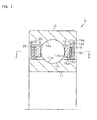
- Fig. 1 is a vertical sectional view of a deep groove ball bearing 1 to which the lubricating structure according to the invention is applied
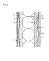
- Fig. 2 is a sectional view of a part of the deep groove ball bearing 1 in a circumferential direction taken along a line A-A in Fig. 1
- Fig. 3 is an exploded perspective view of the deep groove ball bearing 1. As shown in Fig.
- the deep groove ball bearing 1 includes an inner ring 11 formed in an annular shape, an outer ring 12 formed in an annular shape coaxially with the inner ring 11, and a plurality of balls 13 as the rolling elements which are disposed between the inner ring 11 and the outer ring 12 in the circumferential direction.
- a raceway surface 11a for the balls 13 is formed on an outer peripheral surface of the inner ring 11, and a raceway surface 12a for the balls 13 is formed on an inner peripheral surface of the outer ring 12.
- the balls 13 are disposed between the raceway surface 11a and the raceway surface 12a.
- the deep groove ball bearing 1 is a full complement ball bearing in which positions of the balls 13 in the circumferential direction are restricted by relative interference between the adjacent balls 13, as shown in Fig. 2.
- the deep groove ball bearing 1 is a roller bearing which is used in such environment that grease and oil cannot be used as the lubricant in a high temperature atmosphere or the like.
- the lubricating structure for lubricating the deep groove ball bearing 1 of this type includes a graphite ring 14 formed of graphite as solid lubricant, and a wave washer 15 which urges the graphite ring 14 against the balls 13.
- the graphite ring 14 as a lubricating member is formed in a shape of an annular plate, and disposed on side surfaces of a plurality of the balls 13 in the axial direction.
- the wave washer 15 as a resilient member is formed of an annular plate so as to wave in the axial direction, and arranged outside of the graphite ring 14, that is, an opposite side to the balls 13 with respect to the graphite ring 14.
- An inner surface 15a of the wave washer 15 presses an outer face 14a of the graphite ring 14 thereby to urge the graphite ring 14 against the balls 13.
- an inner surface 14b of the graphite ring 14 is abutted against the balls 13 thereby to press the balls 13 in the axial direction.
- a shield 16 in an annular shape for preventing intrusion of a foreign matter or the like into the bearing is disposed outside the wave washer 15.
- the shield 16 is fixed to the outer ring 12 by inserting its outer circumferential edge 16a into a groove 12b which is formed on an inner peripheral surface of the outer ring 12.
- the shield 16 as a holding member is in contact with the outer face 15b of the wave washer 15 so that the wave washer 15 may be held in a compressed state, and falls of the graphite ring 14 and the wave washer 15 can be prevented.
- the graphite ring 14, the wave washer 15 and the shield 16 are assembled, by arranging the graphite ring 14 and the wave washer 15 in an overlapped manner on the side surfaces of the balls 13 in the axial direction, as shown in Fig. 3, and by fixing the shield 16 to the outer ring 12.
- a graphite ring 24 On the opposite side to the side surface of the balls 13 in the axial direction where the graphite ring 14 is arranged, there are assembled a graphite ring 24, a wave washer 25 and a shield 26 which have the same functions and structures as the graphite ring 14, the wave washer 15 and the shield 16, in a symmetrical position with respect to the balls 13.
- the balls 13 start to rotate between the raceway surface 11a and the raceway surface 12a.
- the balls 13 slide along the inner surface 14b of the graphite ring 14, and graphite is transferred from the graphite ring 14 to the balls 13.
- the balls 13 make rolling motions while they spin in different directions from rotation direction of the inner ring 11 or the outer ring 12 due to preload applied between the inner ring and the outer ring.
- the graphite which has been transferred is scattered all over the raceway surface 11a and the raceway surface 12a. In this manner, the graphite is present between the balls 13 and the raceway surface 11a and the raceway surface 12a, whereby lubrication of the deep groove ball bearing 1 is performed.
- the deep groove ball bearing 1 is the full complement ball bearing in which the positions of the balls 13 in the circumferential direction are restricted by relative interference between them, it is not necessary to provide the cage, and it is not necessary to apply the function of the cage to the graphite rings 14, 24.
- the side surfaces of the graphite rings 14, 24 adjacent to the balls 13 can be formed as flat surfaces, and the graphite rings 14, 24 can be made in a simple structure in a shape of an annular plate.
- the graphite rings 14, 15 can be easily machined, and hence, it is possible to simplify the production steps and to reduce the production cost.
- the above described embodiment may be modified as follows.
- the invention is applied to the full complement ball bearing in the above described embodiment, it is possible to apply the invention to a roller bearing of full complement roller bearing.
- the graphite rings 14, 24 as the lubricating member are pressed against side surfaces of the rollers of the roller bearing, it is also possible to favorably lubricate the side surfaces of the rollers where lubrication is required most.
- the deep groove ball bearing 1 is constructed as the full complement ball bearing in the above described embodiment, the deep groove ball bearing 1 may be so constructed that the graphite rings 14, 15 are interposed between the adjacent balls 13.
- Fig. 4 shows an arrangement of the balls 13 and the graphite rings 14, 24 in a sectional view similar to Fig. 2.
- Projected parts 14c, 24c formed in the graphite rings 14, 24 are present between the adjacent balls 13.
- Outer peripheries of the projected parts 14c,' 24c are formed so as to follow an outer contour of the balls 13.
- the graphite rings 14, 24 are provided on opposite side surfaces of the balls in the axial direction in the above described embodiment, the graphite ringmaybe provided on either one of the side surfaces of the ball 13.
- wave washers 15, 25 are employed as the resilient members for urging the graphite rings 14, 24 against the balls 13 in the above described embodiment, other resilient members may be employed such as a rubber member, a helical compression spring, etc. in an annular shape.
- the wave washers 15, 25 are held by means of the shields 16, 26 to give urging force to the graphite rings 14, 24 in the above described embodiment, it is possible to form the shield 16, 26 of leaf spring, so that the shields 16, 26 as the resilient members may directly give the urging force to the graphite rings 14, 24.
- graphite rings 14, 24 formed of graphite are employed as the lubricating members in the above described embodiment, other solid lubricants, for example, an annular member formed of molybdenum disulfide or fluoric resin may be employed. Moreover, the graphite rings 14, 24 may be formed in such a manner that only surface layers at positions where the balls 13 are pressed may be formed of graphite.
Landscapes
- Engineering & Computer Science (AREA)
- General Engineering & Computer Science (AREA)
- Mechanical Engineering (AREA)
- Rolling Contact Bearings (AREA)
Abstract
A lubricating structure of a roller bearing (1) including an inner ring (11), an outer ring (12) and a plurality of rolling elements (13) disposed between the inner (11) and outer (12) rings in a circumferential direction, includes: an annular lubricating member (14) that is formed of solid lubricant and arranged on a side surface of the rolling elements (13) in an axial direction; and a resilient member (15) that urges the lubricating member (14) against the rolling elements (13). With this arrangement, it is possible to depress breakage of components at a time of assembling the roller bearing, and to enhance a yield of the roller bearing.
Description
- The present invention relates to a lubricating structure of a roller bearing which includes an inner ring, an outer ring, and a plurality of rolling elements disposed between the inner and outer rings in a circumferential direction.
- Conventionally, in case where a roller bearing which includes an inner ring, an outer ring, and a plurality of rolling elements disposed between the inner ring and the outer ring in a circumferential direction is used in high temperature atmosphere such as in a heat treating furnace, grease or oil cannot be used as lubricant. Therefore, a cage is formed of graphite functioning as solid lubricant, and the roller bearing is lubricated by making use of transfer of graphite from the cage to the rolling elements. As disclosed in
JP-A-H01-126426 - By the way, the cage as described above is assembled to the roller bearing while holding the rolling elements at equal intervals, after the rolling elements have been incorporated between the inner ring and the outer ring. Therefore, all the rolling elements pass through the openings of the pockets simultaneously when the cage is assembled. For this reason, the pillar portions of the cage cannot be deformed in the circumferential direction, but are largely deformed in a radial direction. Because graphite which is material for the cage is poor in rigidity and strength, and weak, the cage may be sometimes broken when the pillar portions have been deformed in this manner. In the cage as disclosed in
JP-A-H01-126426 - The invention is made in view of the above described circumstances, and it is an object of the invention to provide a lubricating structure of a roller bearing which can enhance a yield of the roller bearing when it is assembled, while lubrication of the roller bearing is reliably conducted.
- In order to attain the above described object, a first aspect of the invention provides a lubricating structure of a roller bearing including an inner ring, an outer ring and a plurality of rolling elements disposed between the inner and outer rings in a circumferential direction, the lubricating structure comprising:
- an annular lubricating member that is formed of solid lubricant and arranged on a side surface of the rolling elements in an axial direction; and
- a resilient member that urges the lubricating member against the rolling elements.
- According to this structure, the annular lubricating member formed of the solid lubricant is provided on the side surface of the plurality of rolling elements which are disposed between the inner ring and the outer ring in the circumferential direction, and the lubricating member is urged against the rolling elements by the resilient member. Therefore, lubrication of the roller bearing can be performed by the lubricating member and the resilient member which are provided on the side surfaces of the respective rolling elements in the axial direction. Specifically, because the lubricating member is urged against the side surfaces of the rolling elements in the axial direction, the solid lubricant is transferred to the rolling elements, and lubrication of the roller bearing is performed. As the results, a structure in which the rolling elements are incorporated into the pockets of the cage which is formed of the solid lubricant, as in the related art, is eliminated, whereby it is possible to depress breakage of components at a time of assembling the roller bearing, and to enhance the yield of the roller bearing.
- A second aspect of the invention provides the lubricating structure of the first aspect in which the resilient member comprises an annular wave washer which urges the lubricating member, and a holding member for holding the wave washer in a compressed state is further provided.
- According to this structure, because the resilient member is the annular wave washer which presses the lubricating member, and the wave washer is held by the holding member in a compressed state, the annular lubricating member can be totally pressed by employing the wave washer having a simple shape. As the results, it is possible to construct the lubricating structure so that the solid lubricant can be reliably transferred to the rolling elements.
- A third aspect of the invention provides a lubricating structure of the first or second aspect, in which the two lubricating members are respectively provided on opposite side surfaces of the rolling elements in the axial direction.
- According to this structure, because the two lubricating members are respectively provided on the opposite side surfaces of the rolling elements in the axial direction, it is possible to construct the lubricating structure so that the rolling elements can be held in good balance by means of the lubricating members on the opposite side surfaces. Moreover, because contact points between the lubricating members and the rolling elements increase, it is possible to enhance lubricating effect of the roller bearing.
- A fourth aspect of the invention provides a lubricating structure of first, second or third aspect, in which the roller bearing is a full complement ball bearing or a full complement roller bearing in which positions of the rolling elements in the circumferential direction are restricted by relative interference between the adjacent rolling elements.
- According to this structure, because the roller bearing is the full complement ball bearing or a full complement roller bearing in which the positions of the rolling elements in the circumferential direction are restricted by relative interference between them, it is not necessary to provide a separate cage, or it is not necessary to applying a function of the cage to the lubricating member. For this reason, a side surface of the lubricating member adjacent to the rolling elements can be formed as a flat face, and the lubricating member can be made in a plate-like shape. As the results, it is possible to form the lubricating member in a simple shape, and hence, it is possible to simplify production steps of the roller bearing and to reduce the production cost.
- A fifth aspect of the invention provides a lubricating structure of any one of the first to fourth aspects, in which the solid lubricant is graphite.
According to this structure, because the solid lubricant is graphite, it is possible to provide a favorable lubricating structure in the roller bearing which is used in a high temperature atmosphere. - According to the invention, the lubricating member in an annular shape formed of the solid lubricant is arranged on the side surfaces of the rolling elements in the axial direction, and the lubricating member is urged against the rolling elements by the resilient member. As the results, it is possible to lubricate the roller bearing by means of the lubricating member and the resilient member in such environment that grease and oil cannot be used. Moreover, a structure in which the rolling elements are incorporated into the pockets of the cage which is formed of the solid lubricant, as in the related art, is eliminated, whereby it is possible to depress breakage of components at a time of assembling the roller bearing and to enhance the yield.
-
- Fig. 1 is a vertical sectional view of a deep groove ball bearing to which a lubricating structure according to the invention is applied.
- Fig. 2 is a sectional view of a part of the deep groove ball bearing in a circumferential direction taken along a line A-A in Fig. 1.
- Fig. 3 is an exploded perspective view of the deep groove ball bearing.
- Fig. 4 is a sectional view of a part of the deep groove ball bearing showing an arrangement in another example of Fig. 2.
- Now, the lubricating structure of the roller bearing according to an embodiment of the invention will be described with reference to Figs. 1 to 3.
Fig. 1 is a vertical sectional view of a deep groove ball bearing 1 to which the lubricating structure according to the invention is applied, Fig. 2 is a sectional view of a part of the deep groove ball bearing 1 in a circumferential direction taken along a line A-A in Fig. 1, and Fig. 3 is an exploded perspective view of the deep groove ball bearing 1. As shown in Fig. 1, the deep groove ball bearing 1 includes aninner ring 11 formed in an annular shape, anouter ring 12 formed in an annular shape coaxially with theinner ring 11, and a plurality ofballs 13 as the rolling elements which are disposed between theinner ring 11 and theouter ring 12 in the circumferential direction. A raceway surface 11a for theballs 13 is formed on an outer peripheral surface of theinner ring 11, and araceway surface 12a for theballs 13 is formed on an inner peripheral surface of theouter ring 12. Theballs 13 are disposed between the raceway surface 11a and theraceway surface 12a. The deep groove ball bearing 1 is a full complement ball bearing in which positions of theballs 13 in the circumferential direction are restricted by relative interference between theadjacent balls 13, as shown in Fig. 2. Moreover, the deep groove ball bearing 1 is a roller bearing which is used in such environment that grease and oil cannot be used as the lubricant in a high temperature atmosphere or the like. - The lubricating structure for lubricating the deep groove ball bearing 1 of this type includes a
graphite ring 14 formed of graphite as solid lubricant, and awave washer 15 which urges thegraphite ring 14 against theballs 13. Thegraphite ring 14 as a lubricating member is formed in a shape of an annular plate, and disposed on side surfaces of a plurality of theballs 13 in the axial direction. The wave washer 15 as a resilient member is formed of an annular plate so as to wave in the axial direction, and arranged outside of thegraphite ring 14, that is, an opposite side to theballs 13 with respect to thegraphite ring 14. Aninner surface 15a of thewave washer 15 presses anouter face 14a of thegraphite ring 14 thereby to urge thegraphite ring 14 against theballs 13. As the results, aninner surface 14b of thegraphite ring 14 is abutted against theballs 13 thereby to press theballs 13 in the axial direction. - A
shield 16 in an annular shape for preventing intrusion of a foreign matter or the like into the bearing is disposed outside thewave washer 15. Theshield 16 is fixed to theouter ring 12 by inserting its outer circumferential edge 16a into agroove 12b which is formed on an inner peripheral surface of theouter ring 12. Theshield 16 as a holding member is in contact with theouter face 15b of thewave washer 15 so that thewave washer 15 may be held in a compressed state, and falls of thegraphite ring 14 and thewave washer 15 can be prevented. - The
graphite ring 14, thewave washer 15 and theshield 16 are assembled, by arranging thegraphite ring 14 and thewave washer 15 in an overlapped manner on the side surfaces of theballs 13 in the axial direction, as shown in Fig. 3, and by fixing theshield 16 to theouter ring 12. - Moreover, on the opposite side to the side surface of the
balls 13 in the axial direction where thegraphite ring 14 is arranged, there are assembled agraphite ring 24, awave washer 25 and ashield 26 which have the same functions and structures as thegraphite ring 14, thewave washer 15 and theshield 16, in a symmetrical position with respect to theballs 13. - Then, lubricating function of the deep groove ball bearing 1 will be described. When the
inner ring 11 and theouter ring 12 rotate relative to each other, theballs 13 start to rotate between the raceway surface 11a and theraceway surface 12a. As theballs 13 rotate, theballs 13 slide along theinner surface 14b of thegraphite ring 14, and graphite is transferred from thegraphite ring 14 to theballs 13. Theballs 13 make rolling motions while they spin in different directions from rotation direction of theinner ring 11 or theouter ring 12 due to preload applied between the inner ring and the outer ring. As the results, the graphite which has been transferred is scattered all over the raceway surface 11a and theraceway surface 12a. In this manner, the graphite is present between theballs 13 and the raceway surface 11a and theraceway surface 12a, whereby lubrication of the deep groove ball bearing 1 is performed. - According to the lubricating structure of the roller bearing in the above described embodiment, the following advantages can be obtained.
- (1) In the above described embodiment, the graphite rings 14, 24 are arranged on the side surfaces of the
balls 13 in the axial direction, and the graphite rings 14, 24 press theballs 13 by urging forces of thewave washers balls 13 by the rollingmotions of theballs 13, whereby lubrication of the deep groove ball bearing 1 can be performed. Moreover, because the graphite rings 14, 24 and thewave washers balls 13 in the axial direction, such a structure in which the rolling elements are incorporated into the pockets of the cage, as in the related art, is eliminated. As the results, it is possible to depress breakage of components at a time of assembling the roller bearing, and to enhance the yield of the roller bearing. - (2) In the above described embodiment, because the graphite rings 14, 24 are held in a compressed state with respect to the
balls 13 by thewave washers shields wave washers balls 13 which are provided in the circumferential direction. - (3) In the above described embodiment, because the graphite rings 14, 24 are provided on the opposite side surfaces of the
balls 13 in the axial direction, and respectively urged against theballs 13, theballs 13 can be held in good balance by means of the graphite rings 14, 24 on both the side surfaces. Moreover, because contact points between the graphite rings 14, 24 and theballs 13 increase, it is possible to enhance the lubricating effects of the deep groove ball bearing 1. - (4) In the above described embodiment, because the deep groove ball bearing 1 is the full complement ball bearing in which the positions of the
balls 13 in the circumferential direction are restricted by relative interference between them, it is not necessary to provide the cage, and it is not necessary to apply the function of the cage to the graphite rings 14, 24. For this reason, the side surfaces of the graphite rings 14, 24 adjacent to theballs 13 can be formed as flat surfaces, and the graphite rings 14, 24 can be made in a simple structure in a shape of an annular plate. As the results, the graphite rings 14, 15 can be easily machined, and hence, it is possible to simplify the production steps and to reduce the production cost. - Further, the above described embodiment may be modified as follows.
Although the invention is applied to the full complement ball bearing in the above described embodiment, it is possible to apply the invention to a roller bearing of full complement roller bearing. In case where the graphite rings 14, 24 as the lubricating member are pressed against side surfaces of the rollers of the roller bearing, it is also possible to favorably lubricate the side surfaces of the rollers where lubrication is required most. - Although the invention is applied to the bearing in which the rolling elements are arranged in a single row in the above described embodiment, it is possible to apply the invention to a bearing in which the rolling elements are arranged in a plurality of rows.
Although the deep groove ball bearing 1 is constructed as the full complement ball bearing in the above described embodiment, the deep groove ball bearing 1 may be so constructed that the graphite rings 14, 15 are interposed between theadjacent balls 13. Fig. 4 shows an arrangement of theballs 13 and the graphite rings 14, 24 in a sectional view similar to Fig. 2. Projectedparts adjacent balls 13. Outer peripheries of the projectedparts 14c,' 24c are formed so as to follow an outer contour of theballs 13. By forming the ball bearing in this manner, a larger contact area can be obtained between the graphite rings 14, 24 and theballs 13, and hence, it is possible to enhance the lubricating effect of the deep groove ball bearing 1. - Although the graphite rings 14, 24 are provided on opposite side surfaces of the balls in the axial direction in the above described embodiment, the graphite ringmaybe provided on either one of the side surfaces of the
ball 13. - Although the
wave washers balls 13 in the above described embodiment, other resilient members may be employed such as a rubber member, a helical compression spring, etc. in an annular shape. - Although the
wave washers shields shield shields - Although the graphite rings 14, 24 formed of graphite are employed as the lubricating members in the above described embodiment, other solid lubricants, for example, an annular member formed of molybdenum disulfide or fluoric resin may be employed. Moreover, the graphite rings 14, 24 may be formed in such a manner that only surface layers at positions where the
balls 13 are pressed may be formed of graphite.
Claims (5)
- A lubricating structure of a roller bearing including an inner ring, an outer ring and a plurality of rolling elements disposed between the inner and outer rings in a circumferential direction, the lubricating structure comprising:an annular lubricating member that is formed of solid lubricant and arranged on a side surface of the rolling elements in an axial direction; anda resilient member that urges the lubricating member against the rolling elements.
- The lubricating structure according to claim 1, wherein
the resilient member comprises an annular wave washer which urges the lubricating member, and
the lubricating structure further comprises a holding member that holds the wave washer in a compressed state. - The lubricating structure according to claim 1, wherein the two lubricating members are respectively provided on the opposite side surfaces of the rolling elements in the axial direction.
- The lubricating structure according to claim 1, wherein the roller bearing is a full complement ball bearing or full complement roller bearing in which positions of the rolling elements in the circumferential direction are restricted by relative interference between the adjacent rolling elements.
- The lubricating structure according to claim 1, wherein the solid lubricant comprises graphite.
Applications Claiming Priority (1)
| Application Number | Priority Date | Filing Date | Title |
|---|---|---|---|
| JP2006186713A JP2008014411A (en) | 2006-07-06 | 2006-07-06 | Rolling bearing lubrication structure |
Publications (1)
| Publication Number | Publication Date |
|---|---|
| EP1876366A2 true EP1876366A2 (en) | 2008-01-09 |
Family
ID=38512684
Family Applications (1)
| Application Number | Title | Priority Date | Filing Date |
|---|---|---|---|
| EP07013322A Withdrawn EP1876366A2 (en) | 2006-07-06 | 2007-07-06 | Lubricating structure of roller bearing |
Country Status (3)
| Country | Link |
|---|---|
| US (1) | US20080008411A1 (en) |
| EP (1) | EP1876366A2 (en) |
| JP (1) | JP2008014411A (en) |
Cited By (1)
| Publication number | Priority date | Publication date | Assignee | Title |
|---|---|---|---|---|
| DE102013221604A1 (en) | 2013-10-24 | 2015-04-30 | Aktiebolaget Skf | Full complement, multi-row rolling bearing |
Families Citing this family (8)
| Publication number | Priority date | Publication date | Assignee | Title |
|---|---|---|---|---|
| JP5561069B2 (en) * | 2009-12-17 | 2014-07-30 | 株式会社ジェイテクト | Bearing device |
| JP2012067884A (en) * | 2010-09-27 | 2012-04-05 | Ntn Corp | Solid-lubrication rolling bearing |
| US9528592B2 (en) | 2012-06-26 | 2016-12-27 | Kinetech Power Company Llc | Solid-lubricated bearing assembly |
| CN107762721B (en) * | 2017-11-10 | 2023-11-28 | 佛山科学技术学院 | A low-resistance wind turbine blade installation structure |
| CN108644227A (en) * | 2018-05-10 | 2018-10-12 | 海宁科巍轴承科技有限公司 | A kind of zirconia ceramics bearing ball |
| DE102018221310A1 (en) * | 2018-12-10 | 2020-06-10 | Aktiebolaget Skf | Roller bearings |
| DE202019101921U1 (en) * | 2019-04-03 | 2020-07-06 | Paul Müller GmbH & Co. KG Unternehmensbeteiligungen | Cage-less rolling bearing |
| CN120739801B (en) * | 2025-08-19 | 2025-12-05 | 江苏万基传动科技有限公司 | Tapered roller bearing for industrial robot |
Family Cites Families (4)
| Publication number | Priority date | Publication date | Assignee | Title |
|---|---|---|---|---|
| JP2532426B2 (en) * | 1987-01-12 | 1996-09-11 | 松下電器産業株式会社 | Solid lubrication bearing device |
| JP2850353B2 (en) * | 1989-03-17 | 1999-01-27 | 日本精工株式会社 | Rolling bearing |
| JPH04181018A (en) * | 1990-11-15 | 1992-06-29 | Internatl Business Mach Corp <Ibm> | Bearing and head positioning device |
| US5399026A (en) * | 1992-12-21 | 1995-03-21 | The Timken Company | Bearing with lubricating ring for providing supplemental lubrication |
-
2006
- 2006-07-06 JP JP2006186713A patent/JP2008014411A/en not_active Withdrawn
-
2007
- 2007-07-03 US US11/822,266 patent/US20080008411A1/en not_active Abandoned
- 2007-07-06 EP EP07013322A patent/EP1876366A2/en not_active Withdrawn
Cited By (1)
| Publication number | Priority date | Publication date | Assignee | Title |
|---|---|---|---|---|
| DE102013221604A1 (en) | 2013-10-24 | 2015-04-30 | Aktiebolaget Skf | Full complement, multi-row rolling bearing |
Also Published As
| Publication number | Publication date |
|---|---|
| US20080008411A1 (en) | 2008-01-10 |
| JP2008014411A (en) | 2008-01-24 |
Similar Documents
| Publication | Publication Date | Title |
|---|---|---|
| US20080008411A1 (en) | Lubricating structure of roller bearing | |
| US20090110340A1 (en) | Bearing apparatus for supporting pinion shaft | |
| WO2009150935A1 (en) | Retainer, deep groove ball bearing, and bearing with seal | |
| US10415643B2 (en) | Rolling bearing | |
| US11181149B2 (en) | Rolling bearing | |
| US20200408260A1 (en) | Inner ring unit and tapered roller bearing | |
| US11236782B2 (en) | Rolling bearing | |
| JP5463687B2 (en) | Rolling bearing | |
| KR100685252B1 (en) | Rolling bearing | |
| US3424507A (en) | Water pump bearing | |
| JP2013145012A (en) | Thrust roller bearing and thrust roller bearing apparatus | |
| JP5655473B2 (en) | Thrust ball bearing | |
| CN111936757A (en) | Bearing device for wheel | |
| JP2000320558A (en) | Synthetic resin cage for roller bearings | |
| JP2012021579A (en) | Roller bearing device | |
| JP2009275799A (en) | Deep groove ball bearing | |
| JP2004169889A (en) | Pinion shaft supporting bearing device, and pinion shaft supporting device | |
| JPH11166540A (en) | Cage for rolling bearing | |
| US11221044B2 (en) | Rolling bearing | |
| JP4269797B2 (en) | Rolling bearing | |
| JP2003120684A (en) | Thrust roller bearing | |
| JP2021167647A (en) | Rolling bearing | |
| JP7029577B2 (en) | Follower bearing | |
| KR102417576B1 (en) | Wave gear and bearing element for a wave gear | |
| JP2010116107A (en) | Axle device for railway vehicle |
Legal Events
| Date | Code | Title | Description |
|---|---|---|---|
| PUAI | Public reference made under article 153(3) epc to a published international application that has entered the european phase |
Free format text: ORIGINAL CODE: 0009012 |
|
| AK | Designated contracting states |
Kind code of ref document: A2 Designated state(s): AT BE BG CH CY CZ DE DK EE ES FI FR GB GR HU IE IS IT LI LT LU LV MC MT NL PL PT RO SE SI SK TR |
|
| AX | Request for extension of the european patent |
Extension state: AL BA HR MK YU |
|
| STAA | Information on the status of an ep patent application or granted ep patent |
Free format text: STATUS: THE APPLICATION HAS BEEN WITHDRAWN |
|
| 18W | Application withdrawn |
Effective date: 20100217 |