EP1876344B1 - Kühlmediumübertritt im Kolben mit kleiner Kompressionshöhe - Google Patents
Kühlmediumübertritt im Kolben mit kleiner Kompressionshöhe Download PDFInfo
- Publication number
- EP1876344B1 EP1876344B1 EP07012120A EP07012120A EP1876344B1 EP 1876344 B1 EP1876344 B1 EP 1876344B1 EP 07012120 A EP07012120 A EP 07012120A EP 07012120 A EP07012120 A EP 07012120A EP 1876344 B1 EP1876344 B1 EP 1876344B1
- Authority
- EP
- European Patent Office
- Prior art keywords
- piston
- cooling medium
- pipe
- piston according
- weld bead
- Prior art date
- Legal status (The legal status is an assumption and is not a legal conclusion. Google has not performed a legal analysis and makes no representation as to the accuracy of the status listed.)
- Revoked
Links
- 239000002826 coolant Substances 0.000 title claims abstract description 42
- 230000006835 compression Effects 0.000 title claims description 7
- 238000007906 compression Methods 0.000 title claims description 7
- 238000001816 cooling Methods 0.000 claims abstract description 38
- 229910000831 Steel Inorganic materials 0.000 claims abstract description 5
- 239000010959 steel Substances 0.000 claims abstract description 5
- 239000011324 bead Substances 0.000 claims description 33
- 238000002485 combustion reaction Methods 0.000 claims description 5
- 239000000853 adhesive Substances 0.000 claims description 2
- 230000001070 adhesive effect Effects 0.000 claims description 2
- 238000003466 welding Methods 0.000 abstract description 17
- 238000000034 method Methods 0.000 description 4
- 230000015572 biosynthetic process Effects 0.000 description 3
- 239000000463 material Substances 0.000 description 3
- 230000003134 recirculating effect Effects 0.000 description 3
- 230000000694 effects Effects 0.000 description 2
- 238000009434 installation Methods 0.000 description 2
- 239000010687 lubricating oil Substances 0.000 description 2
- 239000006228 supernatant Substances 0.000 description 2
- 244000089486 Phragmites australis subsp australis Species 0.000 description 1
- 230000006978 adaptation Effects 0.000 description 1
- 230000002411 adverse Effects 0.000 description 1
- 230000001419 dependent effect Effects 0.000 description 1
- 238000005553 drilling Methods 0.000 description 1
- 238000010438 heat treatment Methods 0.000 description 1
- 238000003780 insertion Methods 0.000 description 1
- 230000037431 insertion Effects 0.000 description 1
- 239000011819 refractory material Substances 0.000 description 1
- 230000000717 retained effect Effects 0.000 description 1
Images


Classifications
-
- F—MECHANICAL ENGINEERING; LIGHTING; HEATING; WEAPONS; BLASTING
- F02—COMBUSTION ENGINES; HOT-GAS OR COMBUSTION-PRODUCT ENGINE PLANTS
- F02F—CYLINDERS, PISTONS OR CASINGS, FOR COMBUSTION ENGINES; ARRANGEMENTS OF SEALINGS IN COMBUSTION ENGINES
- F02F3/00—Pistons
- F02F3/16—Pistons having cooling means
- F02F3/20—Pistons having cooling means the means being a fluid flowing through or along piston
- F02F3/22—Pistons having cooling means the means being a fluid flowing through or along piston the fluid being liquid
-
- F—MECHANICAL ENGINEERING; LIGHTING; HEATING; WEAPONS; BLASTING
- F02—COMBUSTION ENGINES; HOT-GAS OR COMBUSTION-PRODUCT ENGINE PLANTS
- F02F—CYLINDERS, PISTONS OR CASINGS, FOR COMBUSTION ENGINES; ARRANGEMENTS OF SEALINGS IN COMBUSTION ENGINES
- F02F3/00—Pistons
- F02F3/0015—Multi-part pistons
- F02F3/003—Multi-part pistons the parts being connected by casting, brazing, welding or clamping
Definitions
- the invention relates to a piston made of steel with a small compression height for an internal combustion engine.
- the piston comprises a lower part and an upper part, which are connected in each case via joining webs in the region of a contact geometry by means of a friction welding cohesively to a structural unit.
- an inner and an outer cooling channel are integrated, which are connected via at least onedemediumübertritt.
- two openings, one inflow opening and one outflow opening are provided.
- pistons with cooling channels integrated in the piston head are used.
- cooling channels circulates a cooling medium, preferably the lubricating oil of the internal combustion engine.
- the effectiveness of the piston cooling is determined in particular by the exchanged volume of the cooling medium in the cooling channels.
- the present invention has for its object to realize an effective cooling medium exchange between the cooling channels for pistons with a small compression height, despite cramped space conditions.
- the cooling medium transfer is introduced into the circular ring-shaped joining web of the upper part, which may also be referred to as a rib or as an annular web.
- thedemediumübertritt on means that effectively prevent entry of a weld bead of the friction welding in the cooling medium crossing.
- the decisive for the effectiveness of the piston cooling cooling medium exchange between the cooling channels, in particular the effectiveness of the internal cooling channel is thus fully retained, since no negative impact on the cooling effect of the piston cross-sectional constriction sets by the weld bead ofmémediumübertritts.
- the measure according to the invention can be used effectively in pistons with a small compression height and with a deep-trained combustion bowl in the piston crown.
- a friction welding to achieve a cohesive connection of piston components is in the DE 39 06 582 C1 described.
- a component is preferably rubbed on another by a rotating movement under pressure until the contact zone or contact surface has reached the temperature suitable for welding.
- the heating by rubbing is followed by an upsetting process in which the soft or molten areas of the components are torn, plastically deformed and pressed against one another. This forms on both sides of the joint a pressed out of the contact zone Sch Strukturwulst. After cooling of the connected components, the welding process is completed.
- a hole intended to receive a pipe is provided as the coolant passage.
- the tube forms, at least on one side of the joining web, a protrusion exceeding a width "s" or the diameter of the welding bead.
- the dimensionally stable tube is fixed in position in the bore prior to friction welding, so that at least on the side facing the inner cooling channel a supernatant adjusts.
- the pipe length is dimensioned such that its flow cross section is not influenced or concealed by the folded weld bead during friction welding.
- an oval opening into the joining web, which receives a correspondingly oval shaped tube to form the cooling medium transfer.
- An oval or elliptical opening whose short cross-sectional axis is vertically aligned, advantageously reduces the required installation space in the direction of the piston longitudinal extension, without reducing the cross section of the cooling medium transfer.
- a separate tube in a piston is from the DE 699 17 904 T2 known.
- a vertical cooling bore is introduced in the region of the piston pin eye.
- a separate tube is inserted into the cooling bore, which opens into the cooling channel and thus bridges an undercut between the piston pin boss and the piston top part.
- the tube used according to the invention for the formation of the cooling medium transfer, inserted into a bore of the upper part, can be made to vary in length as needed.
- the tube on both sides of the joint exceeds the width or diameter of the respective weld bead.
- a preferred design feature of the invention provides to arrange thedemediumübertritt, in particular the bore for receiving the tube at an angle " ⁇ " ⁇ 60 ° to the piston axis of symmetry.
- This installation position of the cooling medium transfer takes into account the shape of the piston recess and also allows an intensive exchange of cooling medium between the outer and the inner cooling channel.
- the cooling medium transfer preferably includes a tube made of steel.
- a tube of any suitable, refractory material can be used, which is to be permanently connected to the material of the piston.
- a press fit between the pipe and the hole in the joint is suitable.
- the tube can be fixed by means of an adhesive bond.
- a further embodiment according to the invention provides a slotted clamping sleeve as a coolant passage as an alternative to a closed tube.
- the radially preloaded clamping sleeve ensures without additional measures a permanently fixed position in the bore.
- the entry of the weld bead in theissermediumübertritt can also be effectively prevented according to the invention by an integrally connected to the joint, protruding lip.
- the lip which forms thedemediumübertritt together with the bore, a diameter of the Sch workedwulst exceeding width.
- the lip is arranged at the joint on the lower, aligned to the bearing surface of the lower part and upper contour of the bore and thus forms with respect to the weld bead in regions an extended bore.
- the lower part forms a circumferential groove in the area of the contact geometry, the inner bearing surface on the side assigned to the inner cooling channel for receiving the weld bead.
- the profile of the circumferential groove is chosen so that it completely absorbs the weld bead. This arrangement does not require a further component in order to prevent disadvantageous formation of weld beads on the passage of the cooling medium.
- each one undercut performing circulating grooves forms an annular, intended to receive the joint of the upper part opening in the lower part.
- the recirculating grooves define the design of the weld beads on both sides of the joint.
- FIG. 1 shows in a half-sectional view a piston 1 of known type, consisting of a lower part 2 and an upper part 3, which are materially connected in the region of a contact geometry 4 by means of a friction welding, to form a structural unit.
- the upper part 3 of the piston 1 forms a depression 6 in the region of the piston crown 5.
- an inner cooling channel 7 is integrated, which is adapted in the direction of the piston crown 5 to the contour of the piston depression 6.
- a further outer, annular cooling channel 8 extends radially on the outside over the entire length of a ring field 9 and extends into the lower part 2.
- the upper part 3 forms an outer joint 10a, which corresponds via a support surface 11 with the joint web 10b of the lower part 2
- the contact geometry 4 further includes an inner support surface 12, formed by the joining web 13a of the upper part 3 and the joining web 13b of the lower part 2.
- the joining webs 10a, 10b are joined together in a labyrinth-like manner.
- the joining webs 13a, 13b in the region of the support surface 12 are materially connected via a friction welding, which forms a Sch spawulst 14a, 14b on both sides of the joining webs 13a, 13b.
- FIGS. 2 to 5 show, starting from the previously described piston solutions according to the invention, which ensure an unhindered exchange of the cooling medium between the cooling channels 7, 8.
- the following are compared to the known piston according to FIG. 1 According to the invention, described different measures.
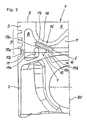
- FIG. 2 shows the cooling medium crossing 16.
- a pipe 18 is inserted into a bore 19 of the joining web 13a.
- the tube 18 is extended so far that it extends to the contour of the lower part 2 and at the same time limits an almost triangular cross-sectional profile for receiving the weld bead 14b.
- the supernatant of the tube 18 with respect to the joint 13a exceeds the measure "s" of the weld bead 14b, according to FIG. 1 ,
- the tube 18 is inserted at an angle " ⁇ " ⁇ 60 ° to an axis of symmetry 20 of the piston 1.
- an oval tube As an alternative to a cylindrically shaped tube 18, it makes sense to use an oval tube, whereby an enlarged flow cross-section can be realized, in particular for the piston 1 with a small compression height.
- an oval tube improves the space for receiving the weld bead 14b.
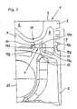
- the piston 1 is shown in connection with the cooling medium transfer 17, which comprises a bore and a lip 21 integrally connected to the joining web 13a.
- the rotationally symmetrical or partially arranged in the region of the bore 19 lip 21 forms together with the support surface 12 a groove which is intended to receive the weld bead 14b.
- the lip 21 effectively prevents the weld bead 14b from affecting the flow area of the bore 19.
- FIG. 4 shows a lower part 2, which includes a circumferential groove 22 for receiving the weld bead 14b in the region of the contact geometry 4 on the side facing the inner cooling channel 7 side. Without a further measure, a disadvantageous influence on the flow cross section of the bore 19 through the weld bead 14b is thus prevented.
- FIG. 5 a lower part 2 with two radially spaced recirculating grooves 22, 23. These each formed as an undercut circulation grooves 22, 23 are intended exclusively for receiving the weld bead 14a and 14b.
- the lower part 2 forms for receiving the joining part 13a connected to the upper part 3, a circular ring-shaped, largely adapted to the width of the joining web 13a opening 24th
Landscapes
- Engineering & Computer Science (AREA)
- Chemical & Material Sciences (AREA)
- Combustion & Propulsion (AREA)
- Mechanical Engineering (AREA)
- General Engineering & Computer Science (AREA)
- Physics & Mathematics (AREA)
- Fluid Mechanics (AREA)
- Pistons, Piston Rings, And Cylinders (AREA)
- Compressor (AREA)
Description
- Die Erfindung betrifft einen aus Stahl hergestellten Kolben mit kleiner Kompressionshöhe für eine Brennkraftmaschine. Der Kolben umfasst ein Unterteil und ein Oberteil, die jeweils über Fügestege im Bereich einer Kontaktgeometrie mittels einer Reibschweißung stoffschlüssig zu einer Baueinheit verbunden werden. In dem Kolben sind ein innerer und ein äußerer Kühlkanal integriert, die über zumindest einen Kühlmediumübertritt verbunden sind. Zur Beaufschlagung der Kühlkanäle mit einem Kühlmedium sind zwei Öffnungen, eine Zuströmöffnung sowie eine Abströmöffnung vorgesehen.
- Um thermisch stark belastete Zonen des Kolbens wie die Mulde im Kolbenboden und den Ringträger im Bereich des Ringfeldes wirksam zu kühlen, werden Kolben mit in dem Kolbenkopf integrierten Kühlkanälen eingesetzt. Durch die bevorzugt als Hohlräume gestalteten Kühlkanäle zirkuliert ein Kühlmedium, vorzugsweise das Schmieröl der Brennkraftmaschine. Die Wirksamkeit der Kolbenkühlung wird insbesondere von dem ausgetauschten Volumen des Kühlmediums in den Kühlkanälen bestimmt.
- Gemäß dem bekannten Stand der Technik, beispielsweise der
EP 0 019 323 A1 , werden zum Kühlmediumaustausch übliche Bohrungen in einen auch als Rippe zu bezeichnenden Fügesteg des Oberteils oder des Unterteils eingebracht. Bei Kolben mit einer kleinen Kompressionshöhe stellen sich relativ kurze Fügestege des Oberteils und des Unterteils ein. Aufgrund des damit verbundenen beengten Bauraums im Bereich der Kontaktgeometrie besteht die Gefahr, dass sich der Strömungsquerschnitt des als Bohrung gestalteten Kühlmediumübertritts bei einem Fügeprozess, dem Reibschweißverfahren, zwischen dem Oberteil und dem Unterteil durch eine Schweißwulst verengt. Dadurch reduziert sich der Kühlmediumaustausch zwischen den Kühlkanälen, verbunden mit einem unmittelbaren nachteiligen Einfluss auf die Kühlung des Kolbens. - Der vorliegenden Erfindung liegt die Aufgabe zugrunde, einen wirksamen Kühlmediumaustausch zwischen den Kühlkanälen für Kolben mit einer kleinen Kompressionshöhe, trotz beengter Bauraumverhältnisse zu realisieren.
- Diese Aufgabe ist durch die Merkmale des Patentanspruchs 1 gelöst. Erfindungsgemäß ist danach vorgesehen, dass der Kühlmediumübertritt in dem kreisringförmig gestalteten, auch als Rippe oder als Ringsteg zu bezeichnenden Fügesteg des Oberteils eingebracht ist. Dazu weist der Kühlmediumübertritt Mittel auf, die einen Eintritt einer Schweißwulst der Reibschweißung in den Kühlmediumübertritt wirksam unterbinden. Durch gezielte Maßnahmen wird gemäß der Erfindung die Schweißwustausbildung unterdrückt oder umgelenkt, um einen Eintritt in den Kühlmediumübertritt zu verhindern, wodurch der Durchströmquerschnitt weder verdeckt noch beeinflusst wird. Der für die Wirksamkeit der Kolbenkühlung entscheidende Kühlmediumaustausch zwischen den Kühlkanälen, insbesondere die Wirksamkeit des Innenkühlkanals bleibt damit uneingeschränkt erhalten, da sich keine auf die Kühlwirkung des Kolbens negativ auswirkende Querschnittsverengung durch die Schweißwulst des Kühlmediumübertritts einstellt. Die erfindungsgemäße Maßnahme ist wirkungsvoll in Kolben mit einer kleinen Kompressionshöhe sowie mit einer tief ausgebildeten Brennraummulde im Kolbenboden einsetzbar.
- Eine Reibschweißung zur Erzielung einer stoffschlüssigen Verbindung von Kolbenbauteilen ist in der
DE 39 06 582 C1 beschrieben. Bei diesem Verfahren wird ein Bauteil unter Druckbelastung vorzugsweise durch eine drehende Bewegung solange auf einem anderen gerieben, bis die Kontaktzone bzw. die Auflagefläche die für eine Schweißung geeignete Temperatur erreicht hat. An das Aufheizen durch Reiben schließt sich ein Stauchvorgang an, bei dem die weichen oder aufgeschmolzenen Bereiche der Bauteile aufgerissen, plastisch deformiert und aufeinander gedrückt werden. Dabei bildet sich auf beiden Seiten des Fügestegs eine aus der Kontaktzone herausgedrückte Schweißwulst. Nach dem Abkühlen der verbundenen Bauteile ist der Schweißvorgang beendet. - Weitere vorteilhafte Ausgestaltungen der Erfindung sind Gegenstand der abhängigen Ansprüche 2 bis 14.
- Gemäß einer bevorzugten Ausgestaltung der Erfindung ist als Kühlmediumübertritt eine zur Aufnahme eines Rohres bestimmte Bohrung vorgesehen. Vorteilhaft bildet das Rohr zumindest auf einer Seite des Fügestegs einen eine Breite "s" oder den Durchmesser der Schweißwulst übertreffenden Überstand. Das formstabile Rohr wird vor dem Reibschweißen so in der Bohrung lagefixiert, dass sich zumindest auf der dem Innenkühlkanal zugewandten Seite ein Überstand einstellt. Die Rohrlänge ist so dimensioniert, dass deren Durchströmquerschnitt auch von der umgelegten Schweißwulst während der Reibschweißung nicht beeinflusst bzw. verdeckt wird.
- Alternativ zu einer zylindrischen Bohrung bietet es sich an, eine ovale Öffnung in den Fügesteg einzubringen, die zur Bildung des Kühlmediumübertritts ein entsprechend oval gestaltetes Rohr aufnimmt. Eine ovale oder elliptische Öffnung, deren kurze Querschnittsachse vertikal ausgerichtet ist, verringert vorteilhaft den erforderlichen Bauraum in Richtung der Kolbenlängserstreckung, ohne dabei den Querschnitt des Kühlmediumübertritts zu verkleinern.
- Die Anwendung eines separaten Rohres in einem Kolben ist aus der
DE 699 17 904 T2 bekannt. Zur Beaufschlagung des Kühlkanals mit Kühlmedium ist im Bereich des Kolbenbolzenauges eine vertikale Kühlungsbohrung eingebracht. Zur Darstellung eines durchgängigen Einlasskanals ist in die Kühlungsbohrung ein separates Rohr eingesetzt, das in den Kühlkanal mündet und somit einen Hinterschnitt zwischen dem Kolbenbolzenauge und dem Kolbenoberteil überbrückt. Dieses bekannte, den Kolben nur in partiellen Bereichen kühlende Konzept erfüllt nicht die an heutige thermisch hochbelasteten Kolben gestellten Kühlungsanforderungen. - Das erfindungsgemäß verwendete Rohr zur Bildung des Kühlmediumübertritts, eingesetzt in eine Bohrung des Oberteils, kann bedarfsabhängig unterschiedlich lang ausgeführt werden. Vorteilhaft übertrifft das Rohr beidseitig des Fügestegs die Breite oder den Durchmesser der jeweiligen Schweißwulst.
- Ein bevorzugtes Auslegungsmerkmal der Erfindung sieht vor, den Kühlmediumübertritt, insbesondere die Bohrung zur Aufnahme des Rohres unter einem Winkel "α" ≥ 60 ° zu der Kolben-Symmetrieachse anzuordnen. Diese Einbaulage des Kühlmediumübertritts berücksichtigt die Formgebung der Kolbenmulde und ermöglicht außerdem einen intensiven Kühlmediumaustausch zwischen dem äußeren und dem inneren Kühlkanal.
- Zur Erzielung einer optimalen Anpassung und Lagefixierung des separaten Rohres in dem Kolben schließt der Kühlmediumübertritt bevorzugt ein aus Stahl hergestelltes Rohr ein. Bevorzugt wird ein Material, das dem Werkstoff des Kolbens insbesondere hinsichtlich des Wärmeausdehnungskoeffizienten zumindest ähnlich ist, so dass mittels einer stoffschlüssigen Verbindung, insbesondere Schweißung, eine zuverlässige Befestigung möglich ist. Alternativ kann ein Rohr aus einem beliebigen, geeigneten, hitzebeständigen Material eingesetzt werden, das mit dem Werkstoff des Kolbens dauerfest zu verbinden ist.
- Alternativ zu einer stoffschlüssigen Verbindung eignet sich ein Pressverband zwischen dem Rohr und der Bohrung in dem Fügesteg. Zum einfachen Einfügen des Rohres in die Bohrung bietet es sich vorteilhaft an, das Rohr zumindest an einem Ende außenseitig mit einer Phase zu versehen. Weiterhin kann erfindungsgemäß das Rohr mittels einer Klebung fixiert werden.
- Eine weitere erfindungsgemäße Ausgestaltung sieht als Kühlmediumübertritt alternativ zu einem geschlossenen Rohr eine geschlitzte Spannhülse vor. Die radial vorgespannte Spannhülse gewährleistet ohne zusätzliche Maßnahmen eine dauerhaft fixierte Lage in der Bohrung.
- Der Eintritt der Schweißwulst in den Kühlmediumübertritt kann gemäß der Erfindung außerdem durch eine einstückig mit dem Fügesteg verbundene, vorstehende Lippe wirksam unterbunden werden. Dazu besitzt die Lippe, die gemeinsam mit der Bohrung den Kühlmediumübertritt bildet, eine den Durchmesser der Schweißwulst übertreffende Breite. Die partiell oder rotationssymmetrisch umlaufend angeordnete, in den inneren Kühlkanal ragende Lippe, beeinflusst während der Reibschweißung ohne ein zusätzliches Bauteil unmittelbar die Gestaltung der Schweißwulst. Die Lippe ist an dem Fügesteg an der unteren, zur Auflagefläche von Unterteil und Oberteil ausgerichteten Kontur der Bohrung angeordnet und bildet damit gegenüber der Schweißwulst bereichsweise eine verlängerte Bohrung.
- Eine weitere erfinderische Maßnahme bezieht sich auf die Gestaltung des Kolbenunterteils. Um eine nachteilige, den Durchströmquerschnitt der Bohrung beeinflussende Schweißwulstbildung zu verhindern, bildet das Unterteil im Bereich der Kontaktgeometrie, der inneren Auflagefläche aufder dem inneren Kühlkanal zugeordneten Seite eine Umlaufnut zur Aufnahme der Schweißwulst. Das Profil der Umlaufnut ist so gewählt, dass dieses die Schweißwulst vollständig aufnimmt. Diese Anordnung erfordert kein weiteres Bauteil, um eine nachteilige Schweißwulstbildung auf den Kühlmediumübertritt zu unterbinden.
- Vorzugsweise bietet es sich an, in das Unterteil im Bereich der inneren Auflagefläche zwei radial beabstandete Umlaufnuten anzuordnen, die beidseitig des Fügestegs jeweils zur Aufnahme einer Schweißwulst bestimmt sind. Die Anordnung der jeweils eine Hinterschneidung darstellenden Umlaufnuten bildet eine kreisringförmige, zur Aufnahme des Fügestegs von dem Oberteil bestimmte Öffnung in dem Unterteil. Gleichzeitig definieren die Umlaufnuten die Gestaltung der Schweißwülste beidseitig des Fügestegs.
- Im Folgenden wird die Erfindung anhand von Ausführungsbeispielen, unter Bezugnahme auf die Zeichnung näher erläutert. Es zeigen:
- Fig.1:
- Einen bekannten Stand der Technik, einen Kolben im Halbschnitt, der als Kühlmediumübertritt eine Bohrung einschließt;
- Fig.2:
- Ein erfindungsgemäßes Ausführungsbeispiel eines im Halbschnitt abgebildeten Kolbens, bei dem ein Rohr den Kühlmediumübertritt bildet;
- Fig.3:
- Ein Detail der Kontaktgeometrie zwischen dem Oberteil und dem Unterteil, wobei das Oberteil einstückig mit einer unterhalb der Bohrung angeordneten Lippe verbundenen ist;
- Fig.4:
- Einen Kolben im Halbschnitt, bei dem im Bereich der Kontaktgeometrie das Unterteil zur Aufnahme der Schweißwulst eine Ringnut aufweist;
- Fig.5:
- Eine der
Figur 4 vergleichbare Darstellung, bei der das Unterteil zwei radial beabstandete Ringnuten einschließt, die jeweils zur Aufnahme einer Schweißwulst bestimmt sind. - Die
Figur 1 zeigt in einer hälftigen Schnittansicht einen Kolben 1 bekannter Bauart, bestehend aus einem Unterteil 2 und einem Oberteil 3, die im Bereich einer Kontaktgeometrie 4 mittels einer Reibschweißung stoffschlüssig, zur Bildung einer Baueinheit verbunden sind. Das Oberteil 3 des Kolbens 1 bildet im Bereich des Kolbenbodens 5 eine Mulde 6. In dem Oberteil 3 ist zentrisch ein innerer Kühlkanal 7 integriert, der in Richtung des Kolbenbodens 5 der Kontur der Kolbenmulde 6 angepasst ist. Ein weiterer äußerer, ringförmig gestalteter Kühlkanal 8 verläuft außenseitig radial beabstandet über die gesamte Länge eines Ringfeldes 9 und erstreckt sich bis in das Unterteil 2. Das Oberteil 3 bildet einen äußeren Fügesteg 10a, der über eine Auflagefläche 11 mit dem Fügesteg 10b des Unterteils 2 korrespondiert. Die Kontaktgeometrie 4 schließt weiterhin eine innere Auflagefläche 12 ein, gebildet durch den Fügesteg 13a des Oberteils 3 und dem Fügesteg 13b des Unterteils 2. Im Bereich der Auflagefläche 11 sind die Fügestege 10a, 10b labyrinthartig formschlüssig ineinander gefügt. Abweichend werden die Fügestege 13a, 13b im Bereich der Auflagefläche 12 über eine Reibschweißung stoffschlüssig verbunden, die beidseitig der Fügestege 13a, 13b eine Schweißwulst 14a, 14b bildet. - Zur Beaufschlagung der Kühlkanäle 7, 8 mit einem Kühlmedium, insbesondere dem Schmieröl der Brennkraftmaschine, wird über eine in
Figur 1 nicht dargestellte Zuströmöffnung das Kühlmedium in den äußeren Kühlkanal 8 eingeleitet und über eine ebenfalls nicht abgebildete Abströmöffnung abgeleitet. Zumindest ein als Bohrung gestalteter Kühlmediumübertritt 15 verbindet den äußeren Kühlkanal 8 mit dem inneren Kühlkanal 7. Wie aus derFigur 1 ersichtlich, wird durch die Gestaltung der Schweißwulst 14b der Bohrungsquerschnitt und folglich der Kühlmediumübertritt 15 weitestgehend verdeckt, verbunden mit einem negativen Einfluss auf den Kühlmediumaustausch zwischen den Kühlkanälen 7, 8. Das Maß "s" verdeutlicht die Breite bzw. den Durchmesser der Schweißwulst 14b, die sichtbar einen Großteil des Kühlmediumübertritts 15 verdeckt. - Die weiteren Ausführungsbeispiele, die
Figuren 2 bis 5 zeigen, ausgehend von dem zuvor beschriebenen Kolben erfindungsgemäße Lösungen, die einen ungehinderten Austausch des Kühlmediums zwischen den Kühlkanälen 7, 8 gewährleisten. Nachfolgend werden die gegenüber dem bekannten Kolben gemäßFigur 1 erfindungsgemäßen, unterschiedlichen Maßnahmen beschrieben. - Die
Figur 2 zeigt den Kühlmediumübertritt 16. Dazu ist ein Rohr 18 in eine Bohrung 19 des Fügestegs 13a eingesetzt. In Richtung des inneren Kühlkanals 7 zeigend ist das Rohr 18 soweit verlängert, dass dieses sich bis an die Kontur des Unterteils 2 erstreckt und gleichzeitig ein nahezu dreieckförmiges Querschnittsprofil begrenzt, zur Aufnahme der Schweißwulst 14b. Der Überstand des Rohres 18 gegenüber dem Fügesteg 13a übertrifft dabei das Maß "s" der Schweißwulst 14b, gemäßFigur 1 . Das Rohr 18 ist unter einem Winkel "α" ≥ 60 ° zu einer Symmetrieachse 20 des Kolbens 1 eingesetzt. Alternativ zu einem zylindrisch geformten Rohr 18 bietet es sich an, ein ovales Rohr zu verwenden, wodurch insbesondere für den Kolben 1 mit einer kleinen Kompressionshöhe ein vergrößerter Durchströmquerschnitt realisierbar ist. Außerdem verbessert ein ovales Rohr den Raum zur Aufnahme der Schweißwulst 14b. - In der
Figur 3 ist der Kolben 1 in Verbindung mit dem Kühlmediumübertritt 17 abgebildet, der eine Bohrung sowie eine einstückig mit dem Fügesteg 13a verbundene Lippe 21 umfasst. Die rotationssymmetrisch verlaufende oder partiell im Bereich der Bohrung 19 angeordnete Lippe 21 bildet gemeinsam mit der Auflagefläche 12 eine Nut, die zur Aufnahme der Schweißwulst 14b bestimmt ist. Die Lippe 21 verhindert wirksam, dass die Schweißwulst 14b den Durchströmquerschnitt der Bohrung 19 beeinflusst. - Die
Figur 4 zeigt ein Unterteil 2, das zur Aufnahme der Schweißwulst 14b im Bereich der Kontaktgeometrie 4 auf der zu dem inneren Kühlkanal 7 gerichteten Seite eine Umlaufnut 22 einschließt. Ohne eine weitere Maßnahme wird damit eine nachteilige Beeinflussung des Durchströmquerschnitts der Bohrung 19 durch die Schweißwulst 14b verhindert. - Alternativ zu
Figur 4 zeigt dieFigur 5 ein Unterteil 2 mit zwei radial beabstandeten Umlaufnuten 22, 23. Diese jeweils als Hinterschnitt ausgebildeten Umlaufnuten 22, 23 sind ausschließlich zur Aufnahme der Schweißwulst 14a bzw. 14b bestimmt. Das Unterteil 2 bildet zur Aufnahme des mit dem Oberteil 3 verbundenen Fügestegs 13a eine kreisringförmig verlaufende, weitestgehend an die Breite des Fügestegs 13a angepasste Öffnung 24. -
- 1
- Kolben
- 2
- Unterteil
- 3
- Oberteil
- 4
- Kontaktgeometrie
- 5
- Kolbenboden
- 6
- Mulde
- 7
- Kühlkanal
- 8
- Kühlkanal
- 9
- Ringfeld
- 10a
- Fügesteg
- 10b
- Fügesteg
- 11
- Auflagefläche
- 12
- Auflagefläche
- 13a
- Fügesteg
- 13b
- Fügesteg
- 14a
- Schweißwulst
- 14b
- Schweißwulst
- 15
- Kühlmediumübertritt
- 16
- Kühlmediumübertritt
- 17
- Kühlmediumübertritt
- 18
- Rohr
- 19
- Bohrung
- 20
- Symmetrieachse
- 21
- Lippe
- 22
- Umlaufnut
- 23
- Umlaufnut
- 24
- Öffnung
Claims (14)
- Aus Stahl hergestellter Kolben (1) mit kleiner Kompressionshöhe für eine Brennkraftmaschine, der einen inneren und einen äußeren Kühlkanal (7, 8) einschließt, die über zumindest einen Kühlmediumübertritt (15,16,17) verbunden sind und der Kolben (1) ein Unterteil (2) und ein Oberteil (3) umfasst, deren Fügestege (10a,10b; 13a,13b) im Bereich einer Kontaktgeometrie (4) über Auflageflächen (11, 12) mittels einer Reibschweißung stoffschlüssig zu einer Baueinheit verbunden werden, dadurch gekennzeichnet, dass der in dem Fügesteg (13a) des Oberteils (3) eingebrachte Kühlmediumübertritt (15,16,17) Mittel aufweist, die einen Eintritt einer Schweißwulst (14a, 14b) der Reibschweißung in den Kühlmediumübertritt (15,16,17) verhindern.
- Kolben nach Anspruch 1, dadurch gekennzeichnet, dass als Kühlmediumübertritt (16) eine Bohrung (19) vorgesehen ist, die zur Aufnahme eines Rohres (18) bestimmt ist, das mit einem eine Breite "s" der Schweißwulst (14a,14b) übertreffenden Überstand aus dem Fügesteg (13a) hervortritt.
- Kolben nach Anspruch 1, dadurch gekennzeichnet, dass der Kühlmediumübertritt (16) ein oval gestaltetes Rohr (18) einschließt, das in eine entsprechend gestaltete Öffnung des Fügestegs (13a) eingesetzt ist.
- Kolben nach Anspruch 2 oder nach Anspruch 3, dadurch gekennzeichnet, dass beidseitig des Fügestegs (13a) das Rohr (18) die Breite "s" der Schweißwulst (14a, 14b) übertrifft.
- Kolben nach Anspruch 2 oder nach Anspruch 3, dadurch gekennzeichnet, dass das Rohr (18) mit unterschiedlichen Längen aus dem Fügesteg (13a) ragt.
- Kolben nach Anspruch 2 oder nach Anspruch 3, dadurch gekennzeichnet, dass in einer Einbaulage das Rohr (18) unter einem Winkel "α" ≥ 60° zu einer Symmetrieachse (20) des Kolbens (1) ausgerichtet ist.
- Kolben nach Anspruch 2 oder nach Anspruch 3, dadurch gekennzeichnet, dass der Kühlmediumübertritt (16) ein aus Stahl hergestelltes Rohr (18) einschließt.
- Kolben nach Anspruch 2 oder nach Anspruch 3, dadurch gekennzeichnet, dass mittels einer Pressung das Rohr (18) in dem Fügesteg (13a) befestigt ist.
- Kolben nach Anspruch 2 oder nach Anspruch 3, dadurch gekennzeichnet, dass eine Klebung zur Lagefixierung des Rohres (18) in dem Fügesteg (13a) vorgesehen ist.
- Kolben nach Anspruch 2 oder nach Anspruch 3, dadurch gekennzeichnet, dass als Rohr (18) eine geschlitzte Spannhülse verwendet wird.
- Kolben nach Anspruch 1, dadurch gekennzeichnet, dass der Fügesteg (13a) zwischen dem Kühlmediumübertritt (17) und der Auflagefläche (12) im Bereich der Kontaktgeometrie (4) eine partiell vorstehende, die Breite "s" der Schweißwulst (14a) übertreffende Lippe (21) aufweist.
- Kolben nach Anspruch 11, dadurch gekennzeichnet, dass die einstückig mit dem Fügesteg (13a) verbundene Lippe (21) rotationssymmetrisch umlaufend ausgebildet ist.
- Kolben nach Anspruch 1, dadurch gekennzeichnet, dass im Bereich der Kontaktgeometrie (4) das Unterteil (2) eine Umlaufnut (22) bildet, die zur Aufnahme der Schweißwulst (14b) der Reibschweißung bestimmt ist.
- Kolben nach Anspruch 1, dadurch gekennzeichnet, dass das Unterteil (2) im Bereich der Kontaktgeometrie (4) zwei in einer Ebene angeordnete, radial zueinander versetzte, zur Aufnahme der Schweißwulst (14a, 14b) bestimmte Umlaufnuten (22, 23) einschließt.
Applications Claiming Priority (1)
| Application Number | Priority Date | Filing Date | Title |
|---|---|---|---|
| DE102006031094A DE102006031094A1 (de) | 2006-07-05 | 2006-07-05 | Kühlmediumübertritt im Kolben mit kleiner Kompressionshöhe |
Publications (2)
| Publication Number | Publication Date |
|---|---|
| EP1876344A1 EP1876344A1 (de) | 2008-01-09 |
| EP1876344B1 true EP1876344B1 (de) | 2011-03-23 |
Family
ID=38610673
Family Applications (1)
| Application Number | Title | Priority Date | Filing Date |
|---|---|---|---|
| EP07012120A Revoked EP1876344B1 (de) | 2006-07-05 | 2007-06-21 | Kühlmediumübertritt im Kolben mit kleiner Kompressionshöhe |
Country Status (3)
| Country | Link |
|---|---|
| EP (1) | EP1876344B1 (de) |
| AT (1) | ATE503097T1 (de) |
| DE (2) | DE102006031094A1 (de) |
Cited By (1)
| Publication number | Priority date | Publication date | Assignee | Title |
|---|---|---|---|---|
| US9108274B2 (en) | 2011-05-05 | 2015-08-18 | Mahle International Gmbh | Method for the production of a piston |
Families Citing this family (5)
| Publication number | Priority date | Publication date | Assignee | Title |
|---|---|---|---|---|
| DE102008034430B4 (de) * | 2008-07-24 | 2015-02-19 | Ks Kolbenschmidt Gmbh | Reibgeschweißter Stahlkolben mit optimiertem Kühlkanal |
| WO2010075959A1 (de) * | 2008-12-15 | 2010-07-08 | Ks Kolbenschmidt Gmbh | Einteileger kolben aus stahl mit optimiertem mehrkomponentenkühlsystem |
| DE102010033882A1 (de) | 2010-08-10 | 2012-02-16 | Mahle International Gmbh | Kolben für einen Verbrennungsmotor |
| DE102012008947A1 (de) | 2012-05-05 | 2013-11-07 | Mahle International Gmbh | Verfahren zur Herstellung eines Kolbens für einen Verbrennungsmotor |
| CN105246639B (zh) * | 2013-02-22 | 2017-07-07 | 马勒国际有限公司 | 有焊接支承的活塞组件 |
Family Cites Families (7)
| Publication number | Priority date | Publication date | Assignee | Title |
|---|---|---|---|---|
| DE3702272A1 (de) * | 1986-04-18 | 1987-10-22 | Mahle Gmbh | Tauchkolben fuer verbrennungsmotoren mit einem von kuehloel durchstroemten hohlraum |
| ES2266011T3 (es) * | 1999-10-08 | 2007-03-01 | Federal-Mogul Corporation | Piston con doble galeria. |
| US20010025568A1 (en) * | 2000-03-28 | 2001-10-04 | Mahle Gmbh | One-piece piston |
| AU2002213255A1 (en) * | 2000-10-18 | 2002-04-29 | Federal Mogul Corporation | Multi-axially forged piston |
| WO2003054371A1 (de) * | 2001-12-21 | 2003-07-03 | Karl Merz | Kolbenringträger mit kühlkanal |
| DE10306115B4 (de) * | 2003-02-14 | 2005-11-24 | Ks Kolbenschmidt Gmbh | Kolben für eine Brennkraftmaschine |
| DE102006002949A1 (de) * | 2006-01-21 | 2007-08-02 | Ks Kolbenschmidt Gmbh | Kühlkanalkolben für eine Brennkraftmaschine |
-
2006
- 2006-07-05 DE DE102006031094A patent/DE102006031094A1/de not_active Withdrawn
-
2007
- 2007-06-21 DE DE502007006754T patent/DE502007006754D1/de active Active
- 2007-06-21 AT AT07012120T patent/ATE503097T1/de active
- 2007-06-21 EP EP07012120A patent/EP1876344B1/de not_active Revoked
Cited By (2)
| Publication number | Priority date | Publication date | Assignee | Title |
|---|---|---|---|---|
| US9108274B2 (en) | 2011-05-05 | 2015-08-18 | Mahle International Gmbh | Method for the production of a piston |
| US9364923B2 (en) | 2011-05-05 | 2016-06-14 | Mahle International Gmbh | Method for the production of a piston |
Also Published As
| Publication number | Publication date |
|---|---|
| DE102006031094A1 (de) | 2008-01-10 |
| ATE503097T1 (de) | 2011-04-15 |
| DE502007006754D1 (de) | 2011-05-05 |
| EP1876344A1 (de) | 2008-01-09 |
Similar Documents
| Publication | Publication Date | Title |
|---|---|---|
| DE102008034430B4 (de) | Reibgeschweißter Stahlkolben mit optimiertem Kühlkanal | |
| EP2188513B1 (de) | Zweiteiliger kolben für einen verbrennungsmotor | |
| EP1583896B1 (de) | Mehrteiliger gekühlter kolben für einen verbrennungsmotor | |
| EP1876344A1 (de) | Kühlmediumübertritt im Kolben mit kleiner Kompressionshöhe | |
| EP2094961A2 (de) | Zweiteiliger kolben für einen verbrennungsmotor | |
| EP1973691A1 (de) | Kühlkanalkolben für eine brennkraftmaschine | |
| DE60207431T2 (de) | Lageranordnung und verfahren zum herstellen einer lageranordnung | |
| DE10247218A1 (de) | Verbesserter Kolben eines Verbrennungsmotors und das Verfahren zu dessen Montage | |
| EP1636474B1 (de) | Verfahren zur herstellung eines einteiligen kolbens für einen verbrennungsmotor | |
| DE10192763B3 (de) | Hydrodynamischer Momentwandler, insbesondere für Kraftfahrzeuge, mit verbesserten Mitteln zur Verbindung des Kolbens mit dem Deckel | |
| DE102010041943A1 (de) | Kühler | |
| DE102021203241A1 (de) | Kolben für eine Brennkraftmaschine und Verfahren zur Herstellung des Kolbens | |
| WO2011110388A2 (de) | Rumpfgruppe einer ladeeinrichtung | |
| DE102015211068B4 (de) | Kombinationsmodul aufweisend einen Einlegering und ein Befestigungselement | |
| EP1573237A1 (de) | Bolzennabe eines kolbens f r einen verbrennungsmotor | |
| EP3421770B1 (de) | Verfahren zur herstellung eines kolbens für eine brennkraftmaschine aus einem kolbenoberteil und aus einem kolbenunterteil | |
| DE102009021852A1 (de) | Bremsscheibe | |
| EP3267061B1 (de) | Gleichlaufgelenk mit integralem gelenkinnenteil und verfahren zur herstellung eines solchen gleichlaufgelenks | |
| DE102011088066A1 (de) | Kolben für Brennkraftmaschinen | |
| DE102009041392A1 (de) | Kolben für eine Verbrennungskraftmaschine | |
| EP4421438B1 (de) | Wärmeübertragerplatte | |
| DE102009020355A1 (de) | Kolben für eine Hubkolbenmaschine | |
| AT528014B1 (de) | Brennkraftmaschine | |
| DE19532068B4 (de) | Abgaskrümmer | |
| DE102006034865B4 (de) | Verfahren zum Verbinden einer Flanschplatte mit einem abgasführenden Rohr und Flansch-Rohr-Verbindung |
Legal Events
| Date | Code | Title | Description |
|---|---|---|---|
| PUAI | Public reference made under article 153(3) epc to a published international application that has entered the european phase |
Free format text: ORIGINAL CODE: 0009012 |
|
| AK | Designated contracting states |
Kind code of ref document: A1 Designated state(s): AT BE BG CH CY CZ DE DK EE ES FI FR GB GR HU IE IS IT LI LT LU LV MC MT NL PL PT RO SE SI SK TR |
|
| AX | Request for extension of the european patent |
Extension state: AL BA HR MK YU |
|
| 17P | Request for examination filed |
Effective date: 20080621 |
|
| AKX | Designation fees paid |
Designated state(s): AT BE BG CH CY CZ DE DK EE ES FI FR GB GR HU IE IS IT LI LT LU LV MC MT NL PL PT RO SE SI SK TR |
|
| GRAP | Despatch of communication of intention to grant a patent |
Free format text: ORIGINAL CODE: EPIDOSNIGR1 |
|
| GRAS | Grant fee paid |
Free format text: ORIGINAL CODE: EPIDOSNIGR3 |
|
| GRAA | (expected) grant |
Free format text: ORIGINAL CODE: 0009210 |
|
| AK | Designated contracting states |
Kind code of ref document: B1 Designated state(s): AT BE BG CH CY CZ DE DK EE ES FI FR GB GR HU IE IS IT LI LT LU LV MC MT NL PL PT RO SE SI SK TR |
|
| REG | Reference to a national code |
Ref country code: GB Ref legal event code: FG4D Free format text: NOT ENGLISH |
|
| REG | Reference to a national code |
Ref country code: CH Ref legal event code: EP |
|
| REG | Reference to a national code |
Ref country code: IE Ref legal event code: FG4D |
|
| REF | Corresponds to: |
Ref document number: 502007006754 Country of ref document: DE Date of ref document: 20110505 Kind code of ref document: P |
|
| REG | Reference to a national code |
Ref country code: DE Ref legal event code: R096 Ref document number: 502007006754 Country of ref document: DE Effective date: 20110505 |
|
| REG | Reference to a national code |
Ref country code: NL Ref legal event code: VDEP Effective date: 20110323 |
|
| PG25 | Lapsed in a contracting state [announced via postgrant information from national office to epo] |
Ref country code: LV Free format text: LAPSE BECAUSE OF FAILURE TO SUBMIT A TRANSLATION OF THE DESCRIPTION OR TO PAY THE FEE WITHIN THE PRESCRIBED TIME-LIMIT Effective date: 20110323 Ref country code: SE Free format text: LAPSE BECAUSE OF FAILURE TO SUBMIT A TRANSLATION OF THE DESCRIPTION OR TO PAY THE FEE WITHIN THE PRESCRIBED TIME-LIMIT Effective date: 20110323 Ref country code: GR Free format text: LAPSE BECAUSE OF FAILURE TO SUBMIT A TRANSLATION OF THE DESCRIPTION OR TO PAY THE FEE WITHIN THE PRESCRIBED TIME-LIMIT Effective date: 20110624 Ref country code: LT Free format text: LAPSE BECAUSE OF FAILURE TO SUBMIT A TRANSLATION OF THE DESCRIPTION OR TO PAY THE FEE WITHIN THE PRESCRIBED TIME-LIMIT Effective date: 20110323 |
|
| LTIE | Lt: invalidation of european patent or patent extension |
Effective date: 20110323 |
|
| PG25 | Lapsed in a contracting state [announced via postgrant information from national office to epo] |
Ref country code: BG Free format text: LAPSE BECAUSE OF FAILURE TO SUBMIT A TRANSLATION OF THE DESCRIPTION OR TO PAY THE FEE WITHIN THE PRESCRIBED TIME-LIMIT Effective date: 20110623 Ref country code: CY Free format text: LAPSE BECAUSE OF FAILURE TO SUBMIT A TRANSLATION OF THE DESCRIPTION OR TO PAY THE FEE WITHIN THE PRESCRIBED TIME-LIMIT Effective date: 20110323 Ref country code: SI Free format text: LAPSE BECAUSE OF FAILURE TO SUBMIT A TRANSLATION OF THE DESCRIPTION OR TO PAY THE FEE WITHIN THE PRESCRIBED TIME-LIMIT Effective date: 20110323 Ref country code: FI Free format text: LAPSE BECAUSE OF FAILURE TO SUBMIT A TRANSLATION OF THE DESCRIPTION OR TO PAY THE FEE WITHIN THE PRESCRIBED TIME-LIMIT Effective date: 20110323 |
|
| REG | Reference to a national code |
Ref country code: IE Ref legal event code: FD4D |
|
| PG25 | Lapsed in a contracting state [announced via postgrant information from national office to epo] |
Ref country code: PT Free format text: LAPSE BECAUSE OF FAILURE TO SUBMIT A TRANSLATION OF THE DESCRIPTION OR TO PAY THE FEE WITHIN THE PRESCRIBED TIME-LIMIT Effective date: 20110725 Ref country code: EE Free format text: LAPSE BECAUSE OF FAILURE TO SUBMIT A TRANSLATION OF THE DESCRIPTION OR TO PAY THE FEE WITHIN THE PRESCRIBED TIME-LIMIT Effective date: 20110323 |
|
| PG25 | Lapsed in a contracting state [announced via postgrant information from national office to epo] |
Ref country code: IS Free format text: LAPSE BECAUSE OF FAILURE TO SUBMIT A TRANSLATION OF THE DESCRIPTION OR TO PAY THE FEE WITHIN THE PRESCRIBED TIME-LIMIT Effective date: 20110723 Ref country code: CZ Free format text: LAPSE BECAUSE OF FAILURE TO SUBMIT A TRANSLATION OF THE DESCRIPTION OR TO PAY THE FEE WITHIN THE PRESCRIBED TIME-LIMIT Effective date: 20110323 Ref country code: ES Free format text: LAPSE BECAUSE OF FAILURE TO SUBMIT A TRANSLATION OF THE DESCRIPTION OR TO PAY THE FEE WITHIN THE PRESCRIBED TIME-LIMIT Effective date: 20110704 Ref country code: SK Free format text: LAPSE BECAUSE OF FAILURE TO SUBMIT A TRANSLATION OF THE DESCRIPTION OR TO PAY THE FEE WITHIN THE PRESCRIBED TIME-LIMIT Effective date: 20110323 Ref country code: RO Free format text: LAPSE BECAUSE OF FAILURE TO SUBMIT A TRANSLATION OF THE DESCRIPTION OR TO PAY THE FEE WITHIN THE PRESCRIBED TIME-LIMIT Effective date: 20110323 |
|
| PG25 | Lapsed in a contracting state [announced via postgrant information from national office to epo] |
Ref country code: MT Free format text: LAPSE BECAUSE OF FAILURE TO SUBMIT A TRANSLATION OF THE DESCRIPTION OR TO PAY THE FEE WITHIN THE PRESCRIBED TIME-LIMIT Effective date: 20110323 Ref country code: NL Free format text: LAPSE BECAUSE OF FAILURE TO SUBMIT A TRANSLATION OF THE DESCRIPTION OR TO PAY THE FEE WITHIN THE PRESCRIBED TIME-LIMIT Effective date: 20110323 |
|
| BERE | Be: lapsed |
Owner name: KS KOLBENSCHMIDT G.M.B.H. Effective date: 20110630 |
|
| PLBI | Opposition filed |
Free format text: ORIGINAL CODE: 0009260 |
|
| PLAX | Notice of opposition and request to file observation + time limit sent |
Free format text: ORIGINAL CODE: EPIDOSNOBS2 |
|
| PG25 | Lapsed in a contracting state [announced via postgrant information from national office to epo] |
Ref country code: IE Free format text: LAPSE BECAUSE OF FAILURE TO SUBMIT A TRANSLATION OF THE DESCRIPTION OR TO PAY THE FEE WITHIN THE PRESCRIBED TIME-LIMIT Effective date: 20110323 |
|
| REG | Reference to a national code |
Ref country code: CH Ref legal event code: PL |
|
| 26 | Opposition filed |
Opponent name: FEDERAL-MOGUL CORPORATION Effective date: 20111223 |
|
| PG25 | Lapsed in a contracting state [announced via postgrant information from national office to epo] |
Ref country code: PL Free format text: LAPSE BECAUSE OF FAILURE TO SUBMIT A TRANSLATION OF THE DESCRIPTION OR TO PAY THE FEE WITHIN THE PRESCRIBED TIME-LIMIT Effective date: 20110323 |
|
| REG | Reference to a national code |
Ref country code: DE Ref legal event code: R026 Ref document number: 502007006754 Country of ref document: DE Effective date: 20111223 |
|
| PG25 | Lapsed in a contracting state [announced via postgrant information from national office to epo] |
Ref country code: BE Free format text: LAPSE BECAUSE OF NON-PAYMENT OF DUE FEES Effective date: 20110630 |
|
| PG25 | Lapsed in a contracting state [announced via postgrant information from national office to epo] |
Ref country code: LI Free format text: LAPSE BECAUSE OF NON-PAYMENT OF DUE FEES Effective date: 20110630 Ref country code: CH Free format text: LAPSE BECAUSE OF NON-PAYMENT OF DUE FEES Effective date: 20110630 |
|
| PG25 | Lapsed in a contracting state [announced via postgrant information from national office to epo] |
Ref country code: IT Free format text: LAPSE BECAUSE OF FAILURE TO SUBMIT A TRANSLATION OF THE DESCRIPTION OR TO PAY THE FEE WITHIN THE PRESCRIBED TIME-LIMIT Effective date: 20110323 |
|
| PLAF | Information modified related to communication of a notice of opposition and request to file observations + time limit |
Free format text: ORIGINAL CODE: EPIDOSCOBS2 |
|
| PLBB | Reply of patent proprietor to notice(s) of opposition received |
Free format text: ORIGINAL CODE: EPIDOSNOBS3 |
|
| PGFP | Annual fee paid to national office [announced via postgrant information from national office to epo] |
Ref country code: FR Payment date: 20120705 Year of fee payment: 6 Ref country code: GB Payment date: 20120622 Year of fee payment: 6 |
|
| PG25 | Lapsed in a contracting state [announced via postgrant information from national office to epo] |
Ref country code: MC Free format text: LAPSE BECAUSE OF NON-PAYMENT OF DUE FEES Effective date: 20110630 |
|
| PG25 | Lapsed in a contracting state [announced via postgrant information from national office to epo] |
Ref country code: LU Free format text: LAPSE BECAUSE OF NON-PAYMENT OF DUE FEES Effective date: 20110621 |
|
| REG | Reference to a national code |
Ref country code: AT Ref legal event code: MM01 Ref document number: 503097 Country of ref document: AT Kind code of ref document: T Effective date: 20120621 |
|
| PG25 | Lapsed in a contracting state [announced via postgrant information from national office to epo] |
Ref country code: TR Free format text: LAPSE BECAUSE OF FAILURE TO SUBMIT A TRANSLATION OF THE DESCRIPTION OR TO PAY THE FEE WITHIN THE PRESCRIBED TIME-LIMIT Effective date: 20110323 |
|
| PG25 | Lapsed in a contracting state [announced via postgrant information from national office to epo] |
Ref country code: AT Free format text: LAPSE BECAUSE OF NON-PAYMENT OF DUE FEES Effective date: 20120621 Ref country code: HU Free format text: LAPSE BECAUSE OF FAILURE TO SUBMIT A TRANSLATION OF THE DESCRIPTION OR TO PAY THE FEE WITHIN THE PRESCRIBED TIME-LIMIT Effective date: 20110323 |
|
| GBPC | Gb: european patent ceased through non-payment of renewal fee |
Effective date: 20130621 |
|
| APBM | Appeal reference recorded |
Free format text: ORIGINAL CODE: EPIDOSNREFNO |
|
| APBP | Date of receipt of notice of appeal recorded |
Free format text: ORIGINAL CODE: EPIDOSNNOA2O |
|
| APAH | Appeal reference modified |
Free format text: ORIGINAL CODE: EPIDOSCREFNO |
|
| REG | Reference to a national code |
Ref country code: FR Ref legal event code: ST Effective date: 20140228 |
|
| PG25 | Lapsed in a contracting state [announced via postgrant information from national office to epo] |
Ref country code: GB Free format text: LAPSE BECAUSE OF NON-PAYMENT OF DUE FEES Effective date: 20130621 |
|
| PG25 | Lapsed in a contracting state [announced via postgrant information from national office to epo] |
Ref country code: FR Free format text: LAPSE BECAUSE OF NON-PAYMENT OF DUE FEES Effective date: 20130701 |
|
| APBQ | Date of receipt of statement of grounds of appeal recorded |
Free format text: ORIGINAL CODE: EPIDOSNNOA3O |
|
| PGFP | Annual fee paid to national office [announced via postgrant information from national office to epo] |
Ref country code: DE Payment date: 20150619 Year of fee payment: 9 |
|
| REG | Reference to a national code |
Ref country code: DE Ref legal event code: R119 Ref document number: 502007006754 Country of ref document: DE |
|
| PG25 | Lapsed in a contracting state [announced via postgrant information from national office to epo] |
Ref country code: DE Free format text: LAPSE BECAUSE OF NON-PAYMENT OF DUE FEES Effective date: 20170103 |
|
| APBU | Appeal procedure closed |
Free format text: ORIGINAL CODE: EPIDOSNNOA9O |
|
| RDAF | Communication despatched that patent is revoked |
Free format text: ORIGINAL CODE: EPIDOSNREV1 |
|
| STAA | Information on the status of an ep patent application or granted ep patent |
Free format text: STATUS: THE PATENT HAS BEEN GRANTED |
|
| REG | Reference to a national code |
Ref country code: DE Ref legal event code: R064 Ref document number: 502007006754 Country of ref document: DE Ref country code: DE Ref legal event code: R103 Ref document number: 502007006754 Country of ref document: DE |
|
| RDAG | Patent revoked |
Free format text: ORIGINAL CODE: 0009271 |
|
| STAA | Information on the status of an ep patent application or granted ep patent |
Free format text: STATUS: PATENT REVOKED |
|
| 27W | Patent revoked |
Effective date: 20180707 |