EP1876098B1 - Vorrichtung zur Betätigung eines Raumflugkörpers durch Reflexion eines Astrallichts auf unterschiedlich ausgerichtete Hilfsspiegel - Google Patents
Vorrichtung zur Betätigung eines Raumflugkörpers durch Reflexion eines Astrallichts auf unterschiedlich ausgerichtete Hilfsspiegel Download PDFInfo
- Publication number
- EP1876098B1 EP1876098B1 EP07111535A EP07111535A EP1876098B1 EP 1876098 B1 EP1876098 B1 EP 1876098B1 EP 07111535 A EP07111535 A EP 07111535A EP 07111535 A EP07111535 A EP 07111535A EP 1876098 B1 EP1876098 B1 EP 1876098B1
- Authority
- EP
- European Patent Office
- Prior art keywords
- mirror
- spacecraft
- light beam
- auxiliary
- positioning means
- Prior art date
- Legal status (The legal status is an assumption and is not a legal conclusion. Google has not performed a legal analysis and makes no representation as to the accuracy of the status listed.)
- Active
Links
- 238000006073 displacement reaction Methods 0.000 claims abstract description 14
- 230000015572 biosynthetic process Effects 0.000 claims description 7
- 239000000523 sample Substances 0.000 claims description 5
- 239000000470 constituent Substances 0.000 claims description 4
- 238000013519 translation Methods 0.000 description 8
- 230000014616 translation Effects 0.000 description 8
- 230000003287 optical effect Effects 0.000 description 5
- 230000000694 effects Effects 0.000 description 4
- 230000004907 flux Effects 0.000 description 3
- 230000001939 inductive effect Effects 0.000 description 3
- 238000012797 qualification Methods 0.000 description 3
- 238000005516 engineering process Methods 0.000 description 2
- 230000005484 gravity Effects 0.000 description 2
- 230000001965 increasing effect Effects 0.000 description 2
- 238000012935 Averaging Methods 0.000 description 1
- 241000581464 Dactyloscopidae Species 0.000 description 1
- 241000287107 Passer Species 0.000 description 1
- 241001639412 Verres Species 0.000 description 1
- 240000008042 Zea mays Species 0.000 description 1
- 238000012550 audit Methods 0.000 description 1
- 230000005465 channeling Effects 0.000 description 1
- 238000013461 design Methods 0.000 description 1
- 239000003344 environmental pollutant Substances 0.000 description 1
- 239000000446 fuel Substances 0.000 description 1
- 239000011521 glass Substances 0.000 description 1
- 238000005286 illumination Methods 0.000 description 1
- 238000005259 measurement Methods 0.000 description 1
- 239000002184 metal Substances 0.000 description 1
- 231100000719 pollutant Toxicity 0.000 description 1
- 241000894007 species Species 0.000 description 1
Images
Classifications
-
- B—PERFORMING OPERATIONS; TRANSPORTING
- B64—AIRCRAFT; AVIATION; COSMONAUTICS
- B64G—COSMONAUTICS; VEHICLES OR EQUIPMENT THEREFOR
- B64G1/00—Cosmonautic vehicles
- B64G1/22—Parts of, or equipment specially adapted for fitting in or to, cosmonautic vehicles
- B64G1/40—Arrangements or adaptations of propulsion systems
- B64G1/407—Solar sailing
-
- B—PERFORMING OPERATIONS; TRANSPORTING
- B64—AIRCRAFT; AVIATION; COSMONAUTICS
- B64G—COSMONAUTICS; VEHICLES OR EQUIPMENT THEREFOR
- B64G1/00—Cosmonautic vehicles
- B64G1/22—Parts of, or equipment specially adapted for fitting in or to, cosmonautic vehicles
- B64G1/24—Guiding or controlling apparatus, e.g. for attitude control
- B64G1/244—Spacecraft control systems
Definitions
- the invention relates to the field of spacecraft, such as observation satellites, flying possibly in formation, probes, or any other spacecraft located on any type of trajectory (for example in orbit around a body, as for example the Earth, or on an interplanetary trajectory), and more precisely that of the actuation of such spacecraft.
- spacecraft such as observation satellites, flying possibly in formation, probes, or any other spacecraft located on any type of trajectory (for example in orbit around a body, as for example the Earth, or on an interplanetary trajectory), and more precisely that of the actuation of such spacecraft.
- actuation means acting on a spacecraft in order to modify finely, or very finely, its position in space and / or its attitude, for example by generating a torque (or moment of forces ) and / or a translation (also called “delta-V").
- attitude and / or the position of a spacecraft must be controlled with a (high) precision. This can for example be the case in a mission using interferometric measurements or very precise scanning laws, or in the case of a formation flight, for example to precisely position various parts of an instrument relative to each other. to others.
- spacecraft are generally provided with thrusters (s) cold gas or electric (s).
- thrusters s
- such propellers are generally not sufficiently accurate, must be subject to an aptitude study (“qualification") because of their complexity, have a limited lifetime when they consume fuel, and may sometimes inducing around the spacecraft a gas / plasma pollutant environment that can be critical in the presence of optical instrument (s).
- Electric propulsion also requires, in general, a high power to operate, which influences the very design of the spacecraft.
- the object of the invention is therefore to improve the situation, and in particular to induce on a spacecraft different couples and / or different translations, as needed, if possible by consuming very little energy. little energy.
- a device intended to actuate a spacecraft, and comprising a fixed primary mirror responsible for reflecting light from a star in the direction of a secondary mirror, in the form of a primary light beam.
- secondary mirror being itself responsible for reflecting in (at least) a selected direction at least a portion of the primary light beam, in the form of a secondary beam.
- a single actuator (at least) is thus necessary to induce the creation of all the possible forces and possible torques around three axes, whereas a device of the prior art always requires several nozzles and as many or more commands (for example valves) for achieve the same result.
- the invention also proposes a spacecraft, such as for example a satellite, a satellite part, a space probe, a part of a space probe, or any other spacecraft located on any type of trajectory in space, equipped with an actuating device of the type shown above.
- a spacecraft such as for example a satellite, a satellite part, a space probe, a part of a space probe, or any other spacecraft located on any type of trajectory in space, equipped with an actuating device of the type shown above.
- the invention also proposes a set of spacecraft intended to fly in formation, and in which at least one of the spacecraft is a spacecraft of the type of the one presented above and is arranged to use its actuation device. to coordinate its trajectory with at least one other of its spacecraft.
- the invention aims to induce on a spacecraft, if possible with a very low energy, and depending on the needs, different pairs and / or different translations.
- the spacecraft is a satellite, for example dedicated to observation, possibly in formation.
- the invention is not limited to this type of spacecraft. It concerns in fact any type of spacecraft whose attitude and / or position must be controlled with (great) precision on any type of trajectory or orbit. Note however that the invention can only relate to situations in which a spacecraft must undergo very small movements (rotation and / or translations). Therefore, the invention is particularly well suited, although not exclusively, to the very precise final control of attitude and / or position within a positioning control loop.
- auxiliary mirrors MAj 1 to 8 as non-limiting example, but it can take any value greater than or equal to two
- positioning means MP MP.
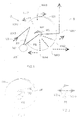
- the primary mirror M1 is installed on the satellite S so as to point in the direction AS of a luminous body, such as for example the sun. It is responsible for reflecting a portion of the light LS which comes from this body in the direction of the secondary mirror M2, in the form of a primary light beam FP.
- the secondary mirror M2 is responsible for reflecting, in (at least) a selected direction and in the form of a secondary beam FS, at least a portion of the primary light beam FP from the primary mirror M1.
- this secondary mirror M2 may be either fixed or orientable (thanks to the positioning means MP) with respect to the primary mirror M1.
- the mirrors among the primary mirror M1, the secondary mirror M2 and the auxiliary mirrors MAj, may together constitute a telescope.
- the secondary mirror M2 may possibly be positioned along the same axis AS as the primary mirror M1 so as to constitute together a telescope.
- the secondary mirror M2 may indeed be positioned off axis with respect to the primary mirror M1. It is essentially to channel the solar energy without trying to create an image or maintain any "optical quality" through the instrument.
- the respective dimensions of the primary mirror M1 and the secondary mirror M2 are chosen in particular as a function of the intensity of the torques and / or forces to be applied to the satellite S.
- auxiliary mirrors can be increased by adding special MAj auxiliary mirrors to obtain a privileged effect in a given direction or around a particular axis, or decrease it by attributing to some at least auxiliary mirrors MAj two functions (for example be both usable to create a rotation (torque forces) and, in combination with another auxiliary mirror MAj, to create a displacement (pure force)).
- the N auxiliary mirrors MAj are placed in selected locations so as to reflect at least part of the secondary light beam FS, which is derived from the secondary mirror M2, in different directions chosen.
- a force solar pressure
- a rotation tilt
- each auxiliary mirror MAj is intended to induce an effect in a chosen direction, and for example two auxiliary mirrors MAj, MAj 'placed in symmetrical positions can induce, when they simultaneously reflect two parts of the secondary light beam FS, a pure pair (around the center of gravity of the satellite S) and therefore a pure rotation, or a pure translation (or delta -V). It is also possible to obtain an effect similar to that obtained in the case of simultaneous illumination of two auxiliary mirrors MAj and MAj 'by consecutively illuminating two auxiliary mirrors MAj and MAj' (or more than two), if one prefers to use a single beam (and not a split beam in two).
- the selective positioning means MP are responsible for selectively causing the reflection of the secondary light beam FS in the direction of one or more selected auxiliary mirrors MAj (for example two), so that each selected auxiliary mirror MAj reflects it in the corresponding selected direction by inducing a selected force or torque, and thus a selected displacement or rotation of the satellite S.
- These selective positioning means MP can control the orientation of the secondary mirror M2 and / or of a reflection mirror M3 interposed between the secondary mirror M2 and the auxiliary mirrors MAj in the path of the secondary light beam FS. They are therefore formed of one or more actuating elements (or actuator (s)).
- the secondary mirror M2 is fixed relative to the primary mirror M1, while a reflecting mirror M3 is secured to the positioning means MP in order to be oriented in different positions chosen by the latter, so as to be able to reflect in each of its positions the secondary light beam FS to at least one auxiliary mirror MAj chosen.
- the reflecting mirror M3 is for example a plane mirror for reflecting at 90 ° (in the direction of an auxiliary mirror MAj as a function of its personal position) the secondary light beam FS coming from the secondary mirror M2.
- the device D can induce on the satellite S, at a given instant, a pair, generally not pure (because associated with a force), whose direction and direction depend on the direction of reflection of the mirror auxiliary MAj selected (that is to say the one that performs the final reflection of secondary light beam FS).
- the positioning means MP are arranged so as to place the reflecting mirror M3 in several different orientations (positions) corresponding respectively to the number N of auxiliary mirrors MAj.
- the positioning means (or actuator) MP may for example comprise a support MS secured to the deflection mirror M3 and moving means ME responsible for moving the support MS.
- the latter may for example be in the form of an axis whose one end is coupled to the rear face of the deflection mirror M3 and the other end (opposite) is moved by the moving means ME.
- the displacement means ME may for example comprise a fixed electric motor relative to the primary mirror M1 and possibly of the step-by-step type.
- This motor ME is for example designed so as to drive the support MS in rotation (or to rotate it) about a rotation axis oriented in a chosen manner according to the respective positions of auxiliary mirrors MAj recipients of the secondary light beam FS.
- the motor ME could also be designed to drive the support MS in translation along an axis oriented in a chosen manner. More generally, the type of drive implemented by the motor ME depends on the respective positions of the auxiliary mirrors MAj with respect to the position of the reflecting mirror M3.
- the moving means ME may be in other forms than a motor (electric). Thus, they can be arranged in the form of piezoelectric actuators. In this case, the reflecting mirror M3 is secured to the piezoelectric actuator.
- Satellite S can be averaged to pure pairs or pure forces that cause pure rotation or translation in a chosen direction by means of an averaging effect.
- the satellite S it is possible to directly subject the satellite S to a pure force or a pure couple chosen (in selected directions and directions).
- a mirror M3 consisting of two half mirrors M3-a and M3-b, as shown in FIG. figure 3 , as well as pairs of auxiliary mirrors MAj placed substantially symmetrically with respect to the reflecting mirror M3 (for example at its periphery as shown in FIG. figure 1 ). Thanks to this arrangement, the secondary light beam FS which reaches the reflecting face of the deflection mirror M3 can be separated by the two half-mirrors M3-a and M3-b into two parts which are respectively reflected towards the two auxiliary mirrors.
- the two half-mirrors M3-a and M3-b can in turn reflect the two parts of the secondary light beam FS in symmetrical directions and directions, thus inducing a torque or a pure force on the satellite S.
- the actuating device D may not include a reflection mirror M3.
- the secondary mirror M2 which is secured to the means of MP positioning in order to be oriented in different positions chosen by them.
- each selected orientation of the secondary mirror M2 is dedicated to reflection to at least one auxiliary mirror MAj chosen.
- the positioning means MP may be of the same type as those described above.
- the secondary mirror M2 plays the role of the mirror M3 described above, and therefore it directly reflects the secondary light beam FS (it generates) to the auxiliary mirrors MAj.
- the actuating device D may comprise a deflection mirror M3 fixed relative to the primary mirror M1 and a secondary mirror M2 secured to the positioning means MP in order to be oriented in different positions chosen by the latter .
- the auxiliary mirrors MAj are for example placed next to each other and oriented in different positions, and each selected orientation of the secondary mirror M2 corresponds to a reflection zone of the secondary light beam FS on the deflection mirror M3 which is dedicated to an auxiliary mirror MAj.
- the positioning means MP may be of the same type as those described above.
- auxiliary mirrors MAj are installed in fixed positions relative to the primary mirror M1. But, this is not an obligation. It can indeed be envisaged that some auxiliary mirrors are fixed relative to the primary mirror M1, while the others can be placed by auxiliary selective positioning means in different positions, chosen so that they can each reflect the secondary light beam FS in different directions chosen to induce different couples or forces. It can also be envisaged that all the auxiliary mirrors MAj can be placed by auxiliary selective positioning means in different positions, so that they can each reflect the secondary light beam FS in different directions chosen so as to induce different couples. Selective positioning means auxiliary devices may be of the same type as the selective positioning means MP described above.
- emergency positioning means may possibly be provided without significantly increasing the load on the satellite S.
- an exemplary embodiment of an actuating device in which all the elements constituting it are described is attached to a spacecraft to be actuated.
- the invention is not limited to this embodiment. Indeed, the elements that constitute the actuating device can be distributed over at least two spacecraft distant from each other and flying in formation.
- the invention also relates to sets of spacecraft intended to fly in formation, and in which at least one spacecraft comprises an actuating device that it uses to coordinate its trajectory with the one at least other spacecraft (as a whole).
Landscapes
- Engineering & Computer Science (AREA)
- Remote Sensing (AREA)
- Chemical & Material Sciences (AREA)
- Combustion & Propulsion (AREA)
- Aviation & Aerospace Engineering (AREA)
- Sustainable Development (AREA)
- Radar, Positioning & Navigation (AREA)
- Life Sciences & Earth Sciences (AREA)
- Automation & Control Theory (AREA)
- Sustainable Energy (AREA)
- Telescopes (AREA)
- Optical Elements Other Than Lenses (AREA)
- Non-Portable Lighting Devices Or Systems Thereof (AREA)
- Lighting Device Outwards From Vehicle And Optical Signal (AREA)
- Mechanical Light Control Or Optical Switches (AREA)
- Details Of Aerials (AREA)
- Navigation (AREA)
Claims (17)
- Vorrichtung (D) zum Betätigen eines Raumflugkörpers (S), die Folgendes umfasst: einen primären festen Spiegel (M1), der Licht von einem Stern in Richtung eines sekundären Spiegels (M2) in Form eines primären Lichtstrahls reflektieren kann, wobei der sekundäre Spiegel (M2) ebenfalls wenigstens einen Teil des primären Lichtstrahls in Form eines sekundären Strahls in eine gewählte Richtung reflektieren kann, dadurch gekennzeichnet, dass er Folgendes umfasst: i) wenigstens zwei Zusatzspiegel (MA1-MA8), die an gewählten Stellen platziert sind und wenigstens einen Teil des von dem sekundären Spiegel (M2) kommenden sekundären Lichtstrahls in gewählten unterschiedlichen Richtungen auf eine solche Weise reflektieren können, dass die verschiedenen Bewegungen des Raumflugkörpers (S) induziert werden, und ii) Mittel zum selektiven Positionieren (MP), um die selektive Reflexion des sekundären Lichtstrahls in der Richtung von wenigstens einem der Zusatzspiegel (MA1-MA8) zu bewirken, so dass die Reflexion auf den/die Zusatzspiegel eine gewählte Bewegung des Raumflugkörpers (S) bewirkt.
- Vorrichtung nach Anspruch 1, dadurch gekennzeichnet, dass der sekundäre Spiegel (M2) mit den Positionierungsmitteln (MP) unlösbar verbunden ist, so dass er durch diese in den verschiedenen Positionen positioniert werden kann, die so gewählt sind, dass jede den sekundären Lichtstrahl zu wenigstens einem gewählten Zusatzspiegel (MA1-MA8) reflektieren kann.
- Vorrichtung nach Anspruch 2, dadurch gekennzeichnet, dass der sekundäre Spiegel (M2) die Aufgabe hat, den sekundären Lichtstrahl in wenigstens zwei Teile zu spalten, so dass diese beiden Teile gleichzeitig in Richtung der beiden gewählten Zusatzspiegel übertragen werden können.
- Vorrichtung nach Anspruch 1, dadurch gekennzeichnet, dass der sekundäre Spiegel (M2) in Bezug auf den primären Spiegel (M1) fest ist, und dadurch, dass er einen Laserspiegel (M3) umfasst, der im Pfad des sekundären Lichtstrahls platziert und mit den Positionierungsmitteln (MP) unlösbar verbunden ist, so dass er durch diese in den verschiedenen Positionen platziert werden kann, die so gewählt sind, dass jede den sekundären Lichtstrahl in Richtung auf wenigstens einen gewählten Zusatzspiegel reflektieren kann.
- Vorrichtung nach Anspruch 1, dadurch gekennzeichnet, dass sie einen Laserspiegel (M3) umfasst, der in Bezug auf den primären Spiegel (M1) fest und im Pfad des sekundären Lichtstrahls platziert ist, und dadurch, dass der sekundäre Spiegel (M2) mit den Positionierungsmitteln (MP) unlösbar verbunden ist, so dass er durch diese in den verschiedenen Positionen platziert werden kann, die so gewählt sind, dass jede den sekundären Lichtstrahl in Richtung auf die verschiedenen Reflexionszonen des Laserspiegels (M3) für die Reflexion in Richtung auf die verschiedenen Zusatzspiegel (MA1-MA8) reflektieren kann.
- Vorrichtung nach einem der Ansprüche 4 und 5, dadurch gekennzeichnet, dass der Laserspiegel (M3) die Aufgabe hat, den sekundären Lichtstrahl in wenigstens zwei Teile zu spalten, so dass diese beiden Teile gleichzeitig in Richtung von zwei gewählten Zusatzspiegeln übertragen werden können.
- Vorrichtung nach einem der Ansprüche 2 bis 6, dadurch gekennzeichnet, dass die Positionierungsmittel (MP) Lagerungsmittel (MS) umfassen, die mit dem sekundären Spiegel (M2) oder dem Laserspiegel (M3) und den Verschiebungsmitteln (ME) zum Verschieben des Lagerungsmittels (MS) unlösbar verbunden sind.
- Vorrichtung nach Anspruch 7, dadurch gekennzeichnet, dass die Verschiebungsmittel (ME) in Form eines Elektromotors ausgebildet sind, um das Lagerungsmittel (MS) in Rotation um eine auf eine gewählte Weise ausgerichtete Rotationsachse zu versetzen.
- Vorrichtung nach Anspruch 7, dadurch gekennzeichnet, dass die Verschiebungsmittel (ME) in Form eines piezoelektrischen Elementes ausgebildet sind.
- Vorrichtung nach einem der Ansprüche 1 bis 9, dadurch gekennzeichnet, dass wenigstens einige der Spiegel aus primärem Spiegel (M1), sekundärem Spiegel (M2) und Zusatzspiegeln (MAj) gemeinsam ein Teleskop bilden.
- Vorrichtung nach einem der Ansprüche 1 bis 10, dadurch gekennzeichnet, dass wenigstens einige der genannten Zusatzspiegel (MA1-MA8) in festen Positionen in Bezug auf den primären Spiegel (M1) installiert sind.
- Vorrichtung nach einem der Ansprüche 1 bis 10, dadurch gekennzeichnet, dass sie zusätzliche Mittel zum selektiven Positionieren umfasst, um wenigstens einige der Zusatzspiegel (MA1-MA8) in unterschiedlichen Positionen zu platzieren, die so gewählt sind, dass sie den sekundären Lichtstrahl in gewählten unterschiedlichen Richtungen reflektieren können.
- Vorrichtung nach einem der Ansprüche 1 bis 12, dadurch gekennzeichnet, dass alle ihre Bestandelemente mit dem zu betätigenden Raumflugkörper verbunden werden können.
- Vorrichtung nach einem der Ansprüche 1 bis 12, dadurch gekennzeichnet, dass ihre Bestandelemente auf wenigstens zwei voneinander entfernte Raumflugkörper verteilt werden können.
- Raumflugkörper (S), dadurch gekennzeichnet, dass er eine Betätigungsvorrichtung (D) nach einem der vorherigen Ansprüche umfasst.
- Raumflugkörper nach Anspruch 15, dadurch gekennzeichnet, dass er aus einer Gruppe ausgewählt ist, die wenigstens Satelliten, Raumsonden, Satellitenteile und Raumsondenteile umfasst.
- Eine Gruppe von Raumflugkörpern (S) zum Fliegen in Formation, dadurch gekennzeichnet, dass wenigstens einer der Raumflugkörper ein Raumflugkörper (S) nach einem der Ansprüche 15 und 16 zum Verwenden seiner Betätigungsvorrichtung (D) ist, um seine Bahn mit wenigstens einem anderen der Raumflugkörper (S) zu koordinieren.
Applications Claiming Priority (1)
| Application Number | Priority Date | Filing Date | Title |
|---|---|---|---|
| FR0652770A FR2903077B1 (fr) | 2006-07-03 | 2006-07-03 | Dispositif d'actionnement d'un engin spatial par reflexion d'une lumiere astrale sur des miroirs auxiliaires orientes differemment |
Publications (2)
| Publication Number | Publication Date |
|---|---|
| EP1876098A1 EP1876098A1 (de) | 2008-01-09 |
| EP1876098B1 true EP1876098B1 (de) | 2010-06-02 |
Family
ID=37710682
Family Applications (1)
| Application Number | Title | Priority Date | Filing Date |
|---|---|---|---|
| EP07111535A Active EP1876098B1 (de) | 2006-07-03 | 2007-07-02 | Vorrichtung zur Betätigung eines Raumflugkörpers durch Reflexion eines Astrallichts auf unterschiedlich ausgerichtete Hilfsspiegel |
Country Status (5)
| Country | Link |
|---|---|
| EP (1) | EP1876098B1 (de) |
| AT (1) | ATE469827T1 (de) |
| DE (1) | DE602007006864D1 (de) |
| ES (1) | ES2345162T3 (de) |
| FR (1) | FR2903077B1 (de) |
Families Citing this family (1)
| Publication number | Priority date | Publication date | Assignee | Title |
|---|---|---|---|---|
| DE102018125364B4 (de) * | 2018-10-12 | 2021-06-02 | Deutsches Zentrum für Luft- und Raumfahrt e.V. | Verfahren und Vorrichtung zum Senden, Übertragen und/oder Empfangen elektromagnetischer Wellen im Weltraum |
Family Cites Families (3)
| Publication number | Priority date | Publication date | Assignee | Title |
|---|---|---|---|---|
| US3171403A (en) * | 1962-05-17 | 1965-03-02 | John C Drescher | Solar heating systems |
| JPH05139393A (ja) * | 1991-11-15 | 1993-06-08 | Nec Corp | 人工衛星姿勢制御装置 |
| US6698693B2 (en) * | 2002-04-16 | 2004-03-02 | Mark P. Davidson | Solar propulsion assist |
-
2006
- 2006-07-03 FR FR0652770A patent/FR2903077B1/fr not_active Expired - Fee Related
-
2007
- 2007-07-02 ES ES07111535T patent/ES2345162T3/es active Active
- 2007-07-02 EP EP07111535A patent/EP1876098B1/de active Active
- 2007-07-02 DE DE602007006864T patent/DE602007006864D1/de active Active
- 2007-07-02 AT AT07111535T patent/ATE469827T1/de not_active IP Right Cessation
Also Published As
| Publication number | Publication date |
|---|---|
| ES2345162T3 (es) | 2010-09-16 |
| ATE469827T1 (de) | 2010-06-15 |
| DE602007006864D1 (de) | 2010-07-15 |
| FR2903077B1 (fr) | 2008-08-29 |
| FR2903077A1 (fr) | 2008-01-04 |
| EP1876098A1 (de) | 2008-01-09 |
Similar Documents
| Publication | Publication Date | Title |
|---|---|---|
| EP0519038B1 (de) | Verfahren zur steuerung des nickwinkels eines satelliten mittels sonnenwinddruck und satellit zur durchführung desselben | |
| EP3381813B1 (de) | Satellit, der elektrische antriebsmittel umfasst, die von bewegungsmitteln und zusätzlichen elektrischen antriebsmitteln mit fester ausrichtung getragen werden | |
| EP1002716B1 (de) | Methode und Vorrichtung zur Lageregelung eines Satelliten | |
| EP2666723B1 (de) | Antriebssystem für die Kontrolle der Umlaufbahn und der Lage von Satelliten | |
| EP1676776B1 (de) | Verbindungsvorrichtung für Elemente einer Raumfahrtausrüstung mit flexiblen ausbringbaren Blättern | |
| FR2954284A1 (fr) | Dispositif de deploiement et de pointage d'elements structurants dans un environnement spatial | |
| EP0055720B1 (de) | Vorrichtung zur orientierung und einstellung einer nutzlast | |
| FR2529166A1 (fr) | Procede de maintien en position d'un satellite par la navigation a l'aide de voiles solaires et vehicule spatial mettant en oeuvre le procede | |
| EP2878539B1 (de) | Düsensystem und verfahren zur kontrolle der umlaufbahn und des verhaltens für geostationären satelliten | |
| FR2710314A1 (fr) | Satellite stabilisé 3-axes à pointage géocentrique en orbite basse à générateur solaire orientable 1-axe. | |
| EP1914815B1 (de) | Drehkranz zur Ausrichtung von zwei Achsen mit piezoelektrischer Motorisierung | |
| EP3144228A1 (de) | Gyroskopisches stellglied mit doppelter kardanführung, aufhängeelement und anschlagelement | |
| FR2545619A1 (fr) | Systeme de miroirs rotatifs pour produire des images du globe terrestre a partir d'un aeronef | |
| EP2052972B1 (de) | Formationsflugvorrichtung, die für eine Koronographie der Sonne vorgesehen ist | |
| EP3045396B1 (de) | Ausrichtungseinheit eines instrumentes | |
| EP1876098B1 (de) | Vorrichtung zur Betätigung eines Raumflugkörpers durch Reflexion eines Astrallichts auf unterschiedlich ausgerichtete Hilfsspiegel | |
| FR2472509A1 (fr) | Configuration de satellite artificiel permettant un controle d'attitude continu suivant trois axes | |
| EP2977321B1 (de) | Verfahren zur positionierung eines satelliten und zum testen seiner nuztlast in der umlaufbahn | |
| EP2537757A1 (de) | Hybridanlage mit mindestens einem Solarpaneel | |
| EP1377863B1 (de) | In dem schatten eines spiegels aufgestelltes montage- und justiergerät für diesen spiegel und mit diesem gerät versehenes optisches system | |
| EP1635485B1 (de) | Optisches Übertragungsverfahren zwischen einem Terminal an Bord eines Raumfahrzeuges, und Raumfahrzeug für das Verfahren | |
| FR2894341A1 (fr) | Dispositif electromecanique comportant un element pouvant tourner autour d'au moins un premier et un deuxieme axe de rotation | |
| CA2049637A1 (fr) | Dispositif bistable sans frottement pour usage spatial, notamment pour l'obturation d'un orifice d'entree d'un instrument optique spatial | |
| EP1676777B1 (de) | Satellit mit Mitteln gegen den Sonnendruck | |
| EP3278168A1 (de) | Elektromagnetischer aktuator für verformbaren spiegel |
Legal Events
| Date | Code | Title | Description |
|---|---|---|---|
| PUAI | Public reference made under article 153(3) epc to a published international application that has entered the european phase |
Free format text: ORIGINAL CODE: 0009012 |
|
| AK | Designated contracting states |
Kind code of ref document: A1 Designated state(s): AT BE BG CH CY CZ DE DK EE ES FI FR GB GR HU IE IS IT LI LT LU LV MC MT NL PL PT RO SE SI SK TR |
|
| AX | Request for extension of the european patent |
Extension state: AL BA HR MK YU |
|
| 17P | Request for examination filed |
Effective date: 20080626 |
|
| AKX | Designation fees paid |
Designated state(s): AT BE BG CH CY CZ DE DK EE ES FI FR GB GR HU IE IS IT LI LT LU LV MC MT NL PL PT RO SE SI SK TR |
|
| GRAP | Despatch of communication of intention to grant a patent |
Free format text: ORIGINAL CODE: EPIDOSNIGR1 |
|
| GRAS | Grant fee paid |
Free format text: ORIGINAL CODE: EPIDOSNIGR3 |
|
| GRAA | (expected) grant |
Free format text: ORIGINAL CODE: 0009210 |
|
| AK | Designated contracting states |
Kind code of ref document: B1 Designated state(s): AT BE BG CH CY CZ DE DK EE ES FI FR GB GR HU IE IS IT LI LT LU LV MC MT NL PL PT RO SE SI SK TR |
|
| REG | Reference to a national code |
Ref country code: GB Ref legal event code: FG4D Free format text: NOT ENGLISH |
|
| REG | Reference to a national code |
Ref country code: CH Ref legal event code: EP |
|
| REG | Reference to a national code |
Ref country code: IE Ref legal event code: FG4D Free format text: LANGUAGE OF EP DOCUMENT: FRENCH |
|
| REF | Corresponds to: |
Ref document number: 602007006864 Country of ref document: DE Date of ref document: 20100715 Kind code of ref document: P |
|
| REG | Reference to a national code |
Ref country code: NL Ref legal event code: T3 |
|
| REG | Reference to a national code |
Ref country code: ES Ref legal event code: FG2A Ref document number: 2345162 Country of ref document: ES Kind code of ref document: T3 |
|
| PG25 | Lapsed in a contracting state [announced via postgrant information from national office to epo] |
Ref country code: SE Free format text: LAPSE BECAUSE OF FAILURE TO SUBMIT A TRANSLATION OF THE DESCRIPTION OR TO PAY THE FEE WITHIN THE PRESCRIBED TIME-LIMIT Effective date: 20100602 Ref country code: LT Free format text: LAPSE BECAUSE OF FAILURE TO SUBMIT A TRANSLATION OF THE DESCRIPTION OR TO PAY THE FEE WITHIN THE PRESCRIBED TIME-LIMIT Effective date: 20100602 |
|
| LTIE | Lt: invalidation of european patent or patent extension |
Effective date: 20100602 |
|
| PG25 | Lapsed in a contracting state [announced via postgrant information from national office to epo] |
Ref country code: SI Free format text: LAPSE BECAUSE OF FAILURE TO SUBMIT A TRANSLATION OF THE DESCRIPTION OR TO PAY THE FEE WITHIN THE PRESCRIBED TIME-LIMIT Effective date: 20100602 Ref country code: LV Free format text: LAPSE BECAUSE OF FAILURE TO SUBMIT A TRANSLATION OF THE DESCRIPTION OR TO PAY THE FEE WITHIN THE PRESCRIBED TIME-LIMIT Effective date: 20100602 Ref country code: FI Free format text: LAPSE BECAUSE OF FAILURE TO SUBMIT A TRANSLATION OF THE DESCRIPTION OR TO PAY THE FEE WITHIN THE PRESCRIBED TIME-LIMIT Effective date: 20100602 Ref country code: AT Free format text: LAPSE BECAUSE OF FAILURE TO SUBMIT A TRANSLATION OF THE DESCRIPTION OR TO PAY THE FEE WITHIN THE PRESCRIBED TIME-LIMIT Effective date: 20100602 |
|
| PG25 | Lapsed in a contracting state [announced via postgrant information from national office to epo] |
Ref country code: PL Free format text: LAPSE BECAUSE OF FAILURE TO SUBMIT A TRANSLATION OF THE DESCRIPTION OR TO PAY THE FEE WITHIN THE PRESCRIBED TIME-LIMIT Effective date: 20100602 Ref country code: CY Free format text: LAPSE BECAUSE OF FAILURE TO SUBMIT A TRANSLATION OF THE DESCRIPTION OR TO PAY THE FEE WITHIN THE PRESCRIBED TIME-LIMIT Effective date: 20100602 |
|
| REG | Reference to a national code |
Ref country code: IE Ref legal event code: FD4D |
|
| BERE | Be: lapsed |
Owner name: THALES Effective date: 20100731 |
|
| PG25 | Lapsed in a contracting state [announced via postgrant information from national office to epo] |
Ref country code: EE Free format text: LAPSE BECAUSE OF FAILURE TO SUBMIT A TRANSLATION OF THE DESCRIPTION OR TO PAY THE FEE WITHIN THE PRESCRIBED TIME-LIMIT Effective date: 20100602 Ref country code: IE Free format text: LAPSE BECAUSE OF FAILURE TO SUBMIT A TRANSLATION OF THE DESCRIPTION OR TO PAY THE FEE WITHIN THE PRESCRIBED TIME-LIMIT Effective date: 20100602 |
|
| PG25 | Lapsed in a contracting state [announced via postgrant information from national office to epo] |
Ref country code: IS Free format text: LAPSE BECAUSE OF FAILURE TO SUBMIT A TRANSLATION OF THE DESCRIPTION OR TO PAY THE FEE WITHIN THE PRESCRIBED TIME-LIMIT Effective date: 20101002 Ref country code: MC Free format text: LAPSE BECAUSE OF NON-PAYMENT OF DUE FEES Effective date: 20100731 Ref country code: PT Free format text: LAPSE BECAUSE OF FAILURE TO SUBMIT A TRANSLATION OF THE DESCRIPTION OR TO PAY THE FEE WITHIN THE PRESCRIBED TIME-LIMIT Effective date: 20101004 Ref country code: SK Free format text: LAPSE BECAUSE OF FAILURE TO SUBMIT A TRANSLATION OF THE DESCRIPTION OR TO PAY THE FEE WITHIN THE PRESCRIBED TIME-LIMIT Effective date: 20100602 Ref country code: RO Free format text: LAPSE BECAUSE OF FAILURE TO SUBMIT A TRANSLATION OF THE DESCRIPTION OR TO PAY THE FEE WITHIN THE PRESCRIBED TIME-LIMIT Effective date: 20100602 Ref country code: CZ Free format text: LAPSE BECAUSE OF FAILURE TO SUBMIT A TRANSLATION OF THE DESCRIPTION OR TO PAY THE FEE WITHIN THE PRESCRIBED TIME-LIMIT Effective date: 20100602 |
|
| PLBE | No opposition filed within time limit |
Free format text: ORIGINAL CODE: 0009261 |
|
| STAA | Information on the status of an ep patent application or granted ep patent |
Free format text: STATUS: NO OPPOSITION FILED WITHIN TIME LIMIT |
|
| PG25 | Lapsed in a contracting state [announced via postgrant information from national office to epo] |
Ref country code: GR Free format text: LAPSE BECAUSE OF FAILURE TO SUBMIT A TRANSLATION OF THE DESCRIPTION OR TO PAY THE FEE WITHIN THE PRESCRIBED TIME-LIMIT Effective date: 20100903 Ref country code: DK Free format text: LAPSE BECAUSE OF FAILURE TO SUBMIT A TRANSLATION OF THE DESCRIPTION OR TO PAY THE FEE WITHIN THE PRESCRIBED TIME-LIMIT Effective date: 20100602 |
|
| 26N | No opposition filed |
Effective date: 20110303 |
|
| REG | Reference to a national code |
Ref country code: DE Ref legal event code: R097 Ref document number: 602007006864 Country of ref document: DE Effective date: 20110302 |
|
| PG25 | Lapsed in a contracting state [announced via postgrant information from national office to epo] |
Ref country code: BE Free format text: LAPSE BECAUSE OF NON-PAYMENT OF DUE FEES Effective date: 20100731 |
|
| PG25 | Lapsed in a contracting state [announced via postgrant information from national office to epo] |
Ref country code: MT Free format text: LAPSE BECAUSE OF FAILURE TO SUBMIT A TRANSLATION OF THE DESCRIPTION OR TO PAY THE FEE WITHIN THE PRESCRIBED TIME-LIMIT Effective date: 20100602 |
|
| REG | Reference to a national code |
Ref country code: CH Ref legal event code: PL |
|
| PG25 | Lapsed in a contracting state [announced via postgrant information from national office to epo] |
Ref country code: LI Free format text: LAPSE BECAUSE OF NON-PAYMENT OF DUE FEES Effective date: 20110731 Ref country code: CH Free format text: LAPSE BECAUSE OF NON-PAYMENT OF DUE FEES Effective date: 20110731 |
|
| PG25 | Lapsed in a contracting state [announced via postgrant information from national office to epo] |
Ref country code: BG Free format text: LAPSE BECAUSE OF FAILURE TO SUBMIT A TRANSLATION OF THE DESCRIPTION OR TO PAY THE FEE WITHIN THE PRESCRIBED TIME-LIMIT Effective date: 20100602 Ref country code: HU Free format text: LAPSE BECAUSE OF FAILURE TO SUBMIT A TRANSLATION OF THE DESCRIPTION OR TO PAY THE FEE WITHIN THE PRESCRIBED TIME-LIMIT Effective date: 20101203 |
|
| PG25 | Lapsed in a contracting state [announced via postgrant information from national office to epo] |
Ref country code: TR Free format text: LAPSE BECAUSE OF FAILURE TO SUBMIT A TRANSLATION OF THE DESCRIPTION OR TO PAY THE FEE WITHIN THE PRESCRIBED TIME-LIMIT Effective date: 20100602 |
|
| PG25 | Lapsed in a contracting state [announced via postgrant information from national office to epo] |
Ref country code: BG Free format text: LAPSE BECAUSE OF FAILURE TO SUBMIT A TRANSLATION OF THE DESCRIPTION OR TO PAY THE FEE WITHIN THE PRESCRIBED TIME-LIMIT Effective date: 20100902 |
|
| REG | Reference to a national code |
Ref country code: FR Ref legal event code: PLFP Year of fee payment: 10 |
|
| REG | Reference to a national code |
Ref country code: FR Ref legal event code: PLFP Year of fee payment: 11 |
|
| REG | Reference to a national code |
Ref country code: FR Ref legal event code: PLFP Year of fee payment: 12 |
|
| PGFP | Annual fee paid to national office [announced via postgrant information from national office to epo] |
Ref country code: LU Payment date: 20200624 Year of fee payment: 14 |
|
| PGFP | Annual fee paid to national office [announced via postgrant information from national office to epo] |
Ref country code: GB Payment date: 20200630 Year of fee payment: 14 Ref country code: NL Payment date: 20200625 Year of fee payment: 14 |
|
| PGFP | Annual fee paid to national office [announced via postgrant information from national office to epo] |
Ref country code: ES Payment date: 20200803 Year of fee payment: 14 |
|
| PGFP | Annual fee paid to national office [announced via postgrant information from national office to epo] |
Ref country code: IT Payment date: 20200625 Year of fee payment: 14 |
|
| REG | Reference to a national code |
Ref country code: NL Ref legal event code: MM Effective date: 20210801 |
|
| GBPC | Gb: european patent ceased through non-payment of renewal fee |
Effective date: 20210702 |
|
| PG25 | Lapsed in a contracting state [announced via postgrant information from national office to epo] |
Ref country code: GB Free format text: LAPSE BECAUSE OF NON-PAYMENT OF DUE FEES Effective date: 20210702 |
|
| PG25 | Lapsed in a contracting state [announced via postgrant information from national office to epo] |
Ref country code: NL Free format text: LAPSE BECAUSE OF NON-PAYMENT OF DUE FEES Effective date: 20210801 Ref country code: LU Free format text: LAPSE BECAUSE OF NON-PAYMENT OF DUE FEES Effective date: 20210702 |
|
| REG | Reference to a national code |
Ref country code: ES Ref legal event code: FD2A Effective date: 20220901 |
|
| PG25 | Lapsed in a contracting state [announced via postgrant information from national office to epo] |
Ref country code: ES Free format text: LAPSE BECAUSE OF NON-PAYMENT OF DUE FEES Effective date: 20210703 |
|
| PG25 | Lapsed in a contracting state [announced via postgrant information from national office to epo] |
Ref country code: IT Free format text: LAPSE BECAUSE OF NON-PAYMENT OF DUE FEES Effective date: 20210731 |
|
| PGFP | Annual fee paid to national office [announced via postgrant information from national office to epo] |
Ref country code: FR Payment date: 20230622 Year of fee payment: 17 |
|
| PGFP | Annual fee paid to national office [announced via postgrant information from national office to epo] |
Ref country code: DE Payment date: 20230613 Year of fee payment: 17 |