EP1875615B1 - System und verfahren zum steuern einer richtantenne für drahtlose kommunikation - Google Patents
System und verfahren zum steuern einer richtantenne für drahtlose kommunikation Download PDFInfo
- Publication number
- EP1875615B1 EP1875615B1 EP06749825A EP06749825A EP1875615B1 EP 1875615 B1 EP1875615 B1 EP 1875615B1 EP 06749825 A EP06749825 A EP 06749825A EP 06749825 A EP06749825 A EP 06749825A EP 1875615 B1 EP1875615 B1 EP 1875615B1
- Authority
- EP
- European Patent Office
- Prior art keywords
- data
- wireless communication
- antenna
- steering
- transceiver
- Prior art date
- Legal status (The legal status is an assumption and is not a legal conclusion. Google has not performed a legal analysis and makes no representation as to the accuracy of the status listed.)
- Ceased
Links
- 238000004891 communication Methods 0.000 title claims abstract description 25
- 238000000034 method Methods 0.000 title claims abstract description 10
- 238000013480 data collection Methods 0.000 claims description 6
- 230000009467 reduction Effects 0.000 claims description 4
- 238000012549 training Methods 0.000 abstract description 10
- 230000007423 decrease Effects 0.000 description 4
- 230000005540 biological transmission Effects 0.000 description 3
- 230000001419 dependent effect Effects 0.000 description 3
- 230000000694 effects Effects 0.000 description 3
- 238000013459 approach Methods 0.000 description 2
- 238000010586 diagram Methods 0.000 description 2
- 238000012986 modification Methods 0.000 description 2
- 230000004048 modification Effects 0.000 description 2
- 238000005457 optimization Methods 0.000 description 2
- 230000008569 process Effects 0.000 description 2
- 238000003491 array Methods 0.000 description 1
- 230000003247 decreasing effect Effects 0.000 description 1
- 238000005516 engineering process Methods 0.000 description 1
- 230000002452 interceptive effect Effects 0.000 description 1
- 230000007246 mechanism Effects 0.000 description 1
- 238000010606 normalization Methods 0.000 description 1
- 230000010363 phase shift Effects 0.000 description 1
- 230000004044 response Effects 0.000 description 1
- 238000006467 substitution reaction Methods 0.000 description 1
- 238000010408 sweeping Methods 0.000 description 1
Images
Classifications
-
- H—ELECTRICITY
- H01—ELECTRIC ELEMENTS
- H01Q—ANTENNAS, i.e. RADIO AERIALS
- H01Q3/00—Arrangements for changing or varying the orientation or the shape of the directional pattern of the waves radiated from an antenna or antenna system
- H01Q3/26—Arrangements for changing or varying the orientation or the shape of the directional pattern of the waves radiated from an antenna or antenna system varying the relative phase or relative amplitude of energisation between two or more active radiating elements; varying the distribution of energy across a radiating aperture
- H01Q3/2605—Array of radiating elements provided with a feedback control over the element weights, e.g. adaptive arrays
Definitions
- the disclosure relates to wireless data communication in general; and, in particular, to wireless data communication system using switched-beam or other directional antenna technology, and the computation of a steering metric (SM) to enable optimization of antenna position (antenna pointing direction).
- SM steering metric
- Wireless data communications systems enable data transmission among two or more network elements.
- An example is a wireless local-area network (WLAN) system, widely used for connecting network elements in homes and offices, based on IEEE standard 802.11x (data rates from 6 to 54 Mbps).
- WLAN wireless local-area network
- Operating range in a wireless system typically decreases with increasing data rate, for a given transmit power (which is often limited by law).
- Typical wireless network elements such as a WLAN access point (AP) use omni-directional antennas for receiving and transmitting data because network elements typically have no knowledge of the location of other network elements desiring a wireless connection.
- Directional antennas have the desirable property of increasing the gain and hence communication range, by focusing the transmitted or received energy into a narrower beam.
- Many known approaches for generating such directional beams are used, including switched antennas, phased arrays of antenna elements, and others.
- One such approach is known as switched-beam antenna.
- the switched-beam antenna has plurality of typically identical beams, each covering an angular range with some fraction of 360 degrees, and oriented to direct the energy of the beam in a different direction.
- a 6-beam antenna has six beams approximately 60 degrees wide, each beam typically oriented 60 degrees from the other, to provide full 360 degree coverage.
- Such antenna provides improved gain compared with an omni-directional antenna, and also provide increased transmit and receive range.
- the "antenna position” refers to the angular position of a directional beam, or the omni-directional pattern.
- each of the many given antenna positions is tried to determine which position gives the best results.
- Each trial evaluates a parameter directly or indirectly indicative of the quality of data and compares the result for each position to determine the optimal position to use for communication.
- RSSI received signal strength indication
- AGC automatic gain control
- RSSI packet error rate
- WLAN standard 802.11 g provides for data rates typically ranging from 6 to 54 Mbps. Lower rates are used in difficult transmission path conditions (long distance, high multi-path, interference from other network elements), while higher rates are used in better conditions. Use of only PER or RSSI to determine optimum antenna position over such a wide range of bandwidth is non-optimal. Therefore, a system and method is needed to effectively optimize antenna positioning when using a directional antenna wireless communication system while minimizing overhead (data bits not directly carrying user information) with a relatively shorter training time than traditionally used.
- European Patent Application Publication No. 1215 893 describes a digital camera having a wideband RF transceiver controlled by a microprocessor to transmit and receive digital image files and other information to and from other remote cameras and communication devices.
- An antenna switch under control of the microprocessor 18 can switch between directional antennas 28 and 30.
- the microprocessor receives an RSSI (received signal strength indicator) signal from the transceiver and periodically switches back and forth (e.g. every few seconds) between the antennas to determine which provides the strongest RSSI signal. This provides spatial diversity to the transceiver. Alternatively, the packet error rate is used.
- RSSI received signal strength indicator
- United States Patent Application Publication No. 2004/218568 describes a method including wirelessly receiving a signal from a remote station, demodulating samples of the received signal and selecting whether or not to communicate with the remote station based on a measure of the received signal quality, e.g., the error vector magnitude (EVM) of data transported via the link between the station and the remote station.
- EVM error vector magnitude
- the present application describes a system and method for determining the optimal antenna position (pointing angle and/or azimuth and/or elevation angle) of a directional antenna in a wireless communication system as set out in the appended claims.
- a steering metric is computed at each of a multiplicity of antenna positions, the steering metric being a function of receiver gain G (indirectly measuring RSSI), packet error rate (PER), and empirically-derived constants.
- the antenna position having the highest steering metric value is then selected as the optimal one to use.
- the method provides improved optimization of antenna position even with widely-varying data rates. Further, reduced data overhead (training bits) is required to determine the optimal antenna position.
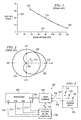
- FIG. 1 is a graph of the known general relationship between data rate and range in a typical 802.11 WLAN system.
- the vertical axis 102 represents data rate in Mbps; the horizontal axis 104 represents a dimensionless measure of relative distance. Actual distance achieved is dependent on many factors other than data rate, such as transmit power, obstructions in the path, interfering signals, and amount and nature of multi-path.
- the plot 110 shows that the range at the highest data rate (data point 106) is less than one-third the range at the lowest data rate (data point 108).
- FIG. 2 illustrates polar plots of antenna gain for both known art omni-directional and directional antenna.
- the length of a vector from the center to the polar plot of gain represents the gain of the antenna as a function of angular position.
- the omni-directional antenna with response plot 204 has equal gain at any azimuth angle 212 around the complete 360 degrees range.
- the plot 206 of the directional antenna shows antenna gain having a peak at 0 degrees azimuth 210, and a null 202 at 180 degrees. Intermediate azimuth values have decreasing gain as the azimuth angle changes between 0 and 180 degrees.
- Gain of the example directional antenna is equal to the omni-directional antenna at an azimuth of approximately 60 degrees, as shown at intersection 208. At 0 degrees azimuth angle, the directional antenna with 60 degree beam width has approximately 4 dBi gain compared to the omni-directional. This increased gain offsets the decrease in range at high data rates seen in FIG. 1 .
- FIG. 3 is a block diagram of a wireless network element 300 using a directional switched-beam antenna and the steering metric computation system for determining an optimal antenna position.
- a data transceiver 302 comprises data transmitter and data receiver. The data transceiver 302 outputs representative of SNR 312, PER 310, and a data rate index K 314. An input control CTL 316 is used to control various transceiver parameters during a training period.
- the transceiver 302 has a driven (when receiving data) and driving (when transmitting data) connection with beam steering subsystem 304 through connection 330.
- the beam steering subsystem 304 is a signal phasing subsystem, which outputs a unique set of multiple signals.
- the beam steering subsystem 304 outputs three signals 324, 326, and 328, substantially identical to the input signal received from transceiver 302, except for variation in amplitude and phase among the three output signals.
- the three variable amplitude and phase signals have a driving and driven connection with a plurality of antenna elements 318, 320, and 322 arrayed in such a pattern as to cause directional beams to be produced dependent on the phase and amplitude variation provided by beam steering subsystem 304.
- the amount of phase shift and amplitude variation applied to each signal is controlled by steering control data on bus 332, this data being generated by a steering metric computer 308.
- the steering metric computer 308 can be any computer configured to execute the steering metric algorithm.
- the steering metric computer 308 and the beam steering unit 304 can be an integrated unit. Further, various units of the wireless network element 300 can be configured in a single integrated unit.
- the transceiver 302 can be an integrated transceiver in the steering metric computer and the steering metric computer 308 can include position control mechanism for the beam steering unit 304.
- Steering control signals from the steering metric computer 308 are typically an N-bit digital word, providing up to 2 ⁇ N selectable antenna positions (directions), including omni-directional.
- the steering metric computer 308 has a driven connection with the RSSI output 312, the PER output 310, and the data rate index K 314 of the transceiver 302. During the training period, the steering metric computer 308 steps through multiple steering control outputs, sweeping the antenna beam through a desired circle or fraction of a circle.
- the disclosed steering metric algorithm provides a combination of desirable properties not available concurrently in the known art, including more optimal selection of antenna position over widely-varying data rates, and reduction in overhead to support this selection process.
- C(k) range typically over 0 to 1, with low C(k) corresponding to high data rates, and high C(k) corresponding to low data rates.
- C(k) range typically over 0 to 1, with low C(k) corresponding to high data rates, and high C(k) corresponding to low data rates.
- k rate: C(k): 1-C(k): 1 .6 Mbps .8 .2 2 8 Mbps .7 .3 3 11 Mbps .6 .4 4 15 Mbps .5 .5 5 21 Mbps .4 .6 6 29 Mbps .3 .7 7 40 Mbps .2 .8 8 54 Mbps .1 .9
- PER(k) is normalized to the approximate range 0 to 1, so that the range of term i.) over the full C(k) range is roughly -0.5 to +0.5.
- (G(k)-meanG)/sigmaG in term ii.) ranges over typically a -1 to +1 range, causing term ii.) to also range over approximately -1 to 1.
- the steering metric (SM) value for each antenna position is stored for comparison with all others generated during the training sweep. When the sweep is complete, one or more of the stored SM values will typically be larger than the others, indicating the optimal antenna position or positions. Control data 332 appropriate to select that optimum position are then output to beam steering 304.
- SM steering metric
- control signals CTL 316 are generated by the steering metric computer 308 and drive transceiver 302, commanding it to modify one or more parameters before a new training sweep.
- Adjustable parameters include, but are not limited to, data rate and transmit power. For example, at high data rates, PER has the most impact on SM. If the first sweep shows little or no variation in PER, transmit power of one of the network elements is reduced to increase PER to a desired level. A sweep at this revised power level will now show a peak in SM at one of the antenna positions. Alternatively, power level may be unchanged, while data rate is increased until PER increases sufficiently.
- RSSI as measured by G has the most impact on SM. If the first sweep shows little or no variation in G, transmit power of one of the network elements is reduced to decrease RSSI to a desired level. A sweep at this revised power level will typically now show a peak in SM at one of the antenna positions.
- the omni-directional antenna position is typically used during adjustment of power level or data rate, moving PER or RSSI to an appropriate target value. If the target value chosen is somewhat less than optimum, one of the plurality of antenna positions other than omni-directional will typically cause a peak in PER or RSSI. Once that optimal antenna position is known, power level or data rate may be adjusted again to increase system margins after training.
Landscapes
- Mobile Radio Communication Systems (AREA)
- Radio Transmission System (AREA)
- Variable-Direction Aerials And Aerial Arrays (AREA)
Claims (6)
- Verfahren zur Bestimmung einer optimalen Antennenposition einer Richtantenne (306) in einem drahtlosen Kommunikationssystem (300), umfassend:Berechnen eines Wertes SM(k) einer Steuerungsmetrik für jeden Datenratenindex (k) (314) für eine Vielzahl von möglichen Strahlpositionen der Richtantenne (306); undAuswählen einer Antennenposition, die den höchsten Wert der Steuerungsmetrik aufweist, für die Richtantenne aus der Vielzahl von möglichen Antennenpositionen, dadurch gekennzeichnet, dass der Wert SM(k) der Steuerungsmetrik gegeben ist durch:

wobei gilt:k=ein Datenratenindex (314) des drahtlosen Kommunikationskanals (302),C(k)=ein Gewichtungsfaktor, der basierend auf der Datenrate des drahtlosen Kommunikationskanals (302) angewandt wird, wobei C(k) einen Wert im Bereich zwischen 0 und 1 annimmt, und wobei ein niedriger Wert von C(k) mit hohen Datenraten und ein niedriger Wert von C(k) mit niedrigen Datenraten korrespondiert,PER(k)=eine geschätzte Paketfehlerrate (310) des drahtlosen Kommunikationskanals (302),G(k)=eine Verringerung der Verstärkung, die während des Empfangs eines Empfangsbestätigungs-Paketes auf dem drahtlosen Kommunikationskanal (302) angewandt wird, und welche direkt proportional zu der empfangenen Signalstärke (RSSI) ist,meanG=ein konstanter mittlerer Wert von G(k), der basierend auf empirischen Daten einer Ansammlung von verschiedenen Datenraten bestimmt wird, undsigmaG=eine Standardabweichung von G(k), die basierend auf empirischen Daten einer Ansammlung von verschiedenen Datenraten bestimmt wird. - Verfahren nach Anspruch 1, wobei die Paketfehlerrate (PER) (310), der empfangene Signalstärkenindikator (RSSI) und der Datenratenindex (k) von einem Transceiver (302), der dazu ausgelegt ist Daten auf dem drahtlosen Kommunikationskanal zu empfangen, bestimmt wird.
- System zur Bestimmung einer optimalen Antennenposition einer Richtantenne in einem drahtlosen Kommunikationssystem (300), umfassend:einen Transceiver (302);eine Strahlsteuerungseinheit (304), die mit dem Transceiver (302) gekoppelt ist; undeine Einheit (308) zur Berechnung einer Steuerungsmetrik, die mit dem Transceiver (302) gekoppelt ist, wobei die Einheit (308) zur Berechnung der Steuerungsmetrik dazu ausgelegt ist:einen Wert SM(k) der Steuerungsmetrik bei jedem Datenratenindex (k) (314) für eine Vielzahl von möglichen Antennenpositionen der Richtantenne (308) zu berechnen; undeine Antennenpositionen, die den höchsten Wert der Steuerungsmetrik aufweist, aus der Vielzahl von möglichen Antennenpositionen für die Richtantenne (306) auszuwählen, dadurch gekennzeichnet, dass der Wert SM(k) der Steuerungsmetrik gegeben ist durch:k=ein Datenratenindex (314) des drahtlosen Kommunikationskanals (302),C(k)=ein Gewichtungsfaktor, der basierend auf der Datenrate des drahtlosen Kommunikationskanals (302) angewandt wird, wobei C(k) einen Wert im Bereich zwischen 0 und 1 annimmt, und wobei ein niedriger Wert von C(k) mit hohen Datenraten und ein niedriger Wert von C(k) mit niedrigen Datenraten korrespondiert,PER(k)=eine geschätzte Paketfehlerrate (310) des drahtlosen Kommunikationskanals (302),G(k)=eine Verringerung der Verstärkung, die während des Empfangs eines Empfangsbestätigungs-Paketes auf dem drahtlosen Kommunikationskanal (302) angewandt wird, und welche direkt proportional zu der empfangenen Signalstärke (RSSI) ist,meanG=ein konstanter mittlerer Wert von G(k), der basierend auf empirischen Daten einer Ansammlung von verschiedenen Datenraten bestimmt wird, undsigmaG=eine Standardabweichung von G(k), die basierend auf empirischen Daten einer Ansammlung von verschiedenen Datenraten bestimmt wird.
- System nach Anspruch 3, wobei die Strahlsteuerungseinheit (304) dazu eingerichtet ist, eine Position der Richtantenne (306) entsprechend einer optimalen Antennenposition einzustellen.
- System nach Anspruch 3, wobei die Paketfehlerrate (PER) (310), der empfangene Signalstärkeindikator (RSSI) und der Datenratenindex (k) (314) durch den Transceiver (302), der dazu eingerichtet ist Daten auf dem drahtlosen Kommunikationskanal zu empfangen, bestimmt sind.
- System nach Anspruch 3, wobei der Transceiver (302), die Strahlsteuerungseinheit (304) und die Einheit (308) zur Berechnung der Steuerungsmetrik in eine einzige Einheit integriert sind.
Applications Claiming Priority (2)
| Application Number | Priority Date | Filing Date | Title |
|---|---|---|---|
| US11/107,046 US7120468B1 (en) | 2005-04-15 | 2005-04-15 | System and method for steering directional antenna for wireless communications |
| PCT/US2006/013572 WO2006113250A1 (en) | 2005-04-15 | 2006-04-11 | System and method for steering directional antenna for wireless communication |
Publications (3)
| Publication Number | Publication Date |
|---|---|
| EP1875615A1 EP1875615A1 (de) | 2008-01-09 |
| EP1875615A4 EP1875615A4 (de) | 2010-01-13 |
| EP1875615B1 true EP1875615B1 (de) | 2011-07-06 |
Family
ID=37072498
Family Applications (1)
| Application Number | Title | Priority Date | Filing Date |
|---|---|---|---|
| EP06749825A Ceased EP1875615B1 (de) | 2005-04-15 | 2006-04-11 | System und verfahren zum steuern einer richtantenne für drahtlose kommunikation |
Country Status (5)
| Country | Link |
|---|---|
| US (1) | US7120468B1 (de) |
| EP (1) | EP1875615B1 (de) |
| JP (1) | JP4536815B2 (de) |
| CN (1) | CN101160730B (de) |
| WO (1) | WO2006113250A1 (de) |
Cited By (1)
| Publication number | Priority date | Publication date | Assignee | Title |
|---|---|---|---|---|
| US9008588B2 (en) | 2013-05-21 | 2015-04-14 | International Business Machines Corporation | System and method for the calibration and verification of wireless networks with control network |
Families Citing this family (26)
| Publication number | Priority date | Publication date | Assignee | Title |
|---|---|---|---|---|
| US20070047560A1 (en) * | 2005-08-31 | 2007-03-01 | Accton Technology Corporation | Wireless bridge with beam-switching antenna arrays and method thereof |
| US7489670B2 (en) | 2005-12-27 | 2009-02-10 | Celeno Communications Ltd. | Device, system and method of uplink/downlink communication in wireless network |
| US7751353B2 (en) * | 2005-12-29 | 2010-07-06 | Celeno Communications (Israel) Ltd. | Device, system and method of securing wireless communication |
| US7656965B2 (en) * | 2005-12-29 | 2010-02-02 | Celeno Communications (Israel) Ltd. | Method of secure WLAN communication |
| US9071435B2 (en) | 2005-12-29 | 2015-06-30 | Celeno Communications Ltd. | System and method for tuning transmission parameters in multi-user multiple-input-multiple-output systems with aged and noisy channel estimation |
| US7570624B2 (en) | 2005-12-29 | 2009-08-04 | Celeno Communications (Israel) Ltd. | Device, system and method of uplink/downlink communication in wireless network |
| US7672400B2 (en) * | 2005-12-29 | 2010-03-02 | Celeno Communications (Israel) Ltd. | Method of secure WLAN communication |
| US20070153760A1 (en) * | 2005-12-29 | 2007-07-05 | Nir Shapira | Method, apparatus and system of spatial division multiple access communication in a wireless local area network |
| US8175532B2 (en) * | 2006-06-06 | 2012-05-08 | Qualcomm Incorporated | Apparatus and method for wireless communication via at least one of directional and omni-direction antennas |
| US8290551B2 (en) * | 2008-08-06 | 2012-10-16 | Direct Beam Inc. | Systems and methods for efficiently positioning a directional antenna module to receive and transmit the most effective band width of wireless transmissions |
| US20110143673A1 (en) * | 2008-08-06 | 2011-06-16 | Direct-Beam Inc. | Automatic positioning of diversity antenna array |
| JP5251605B2 (ja) * | 2009-03-02 | 2013-07-31 | ソニー株式会社 | 通信装置、および利得制御方法 |
| CN102571182B (zh) * | 2012-01-20 | 2014-08-13 | 杭州华三通信技术有限公司 | 一种无线局域网中接收天线的选择方法和装置 |
| US9088313B2 (en) | 2013-02-16 | 2015-07-21 | Cable Television Laboratories, Inc. | Multiple-input multiple-output (MIMO) communication system |
| US9923621B2 (en) | 2013-02-16 | 2018-03-20 | Cable Television Laboratories, Inc. | Multiple-input multiple-output (MIMO) communication system |
| US9287956B2 (en) * | 2013-02-16 | 2016-03-15 | Cable Television Laboratories, Inc. | Multiple-input multiple-output (MIMO) communication system |
| GB2525532B (en) * | 2013-02-16 | 2020-09-02 | Cable Television Laboratories Inc | Multiple-Input multiple-output (MMO) communication system |
| EP2889957A1 (de) * | 2013-12-30 | 2015-07-01 | Clemens Rheinfelder | Aktivantennensystem mit verteiltem Sende/Empfänger System |
| CN104779982B (zh) * | 2014-01-10 | 2018-09-18 | 启碁科技股份有限公司 | 射频信号处理方法及无线通讯装置 |
| CN108123747B (zh) * | 2014-09-16 | 2020-08-04 | 安科讯(福建)科技有限公司 | 一种基于扇区切换的wlan基站信号覆盖方法 |
| US9615266B1 (en) | 2016-04-04 | 2017-04-04 | Cisco Technology, Inc. | Networking device with an electronically steerable directional antenna array |
| US11158939B2 (en) | 2016-11-10 | 2021-10-26 | University Of South Florida | Mm-wave wireless channel control using spatially adaptive antenna arrays |
| JP6692934B2 (ja) | 2017-01-27 | 2020-05-13 | 日本電信電話株式会社 | 無線基地局および送受信電力制御方法 |
| WO2018167284A1 (en) * | 2017-03-17 | 2018-09-20 | Sony Corporation | Communication device and method using virtual sector forming |
| US10321463B1 (en) * | 2018-01-16 | 2019-06-11 | Dell Products, Lp | Method and apparatus for an accelerometer assisted control system for a reconfigurable antenna communication device |
| US11153922B2 (en) | 2019-10-15 | 2021-10-19 | Rosemount Aerospace, Inc. | Directional wireless communications onboard aircraft |
Family Cites Families (8)
| Publication number | Priority date | Publication date | Assignee | Title |
|---|---|---|---|---|
| US6009124A (en) * | 1997-09-22 | 1999-12-28 | Intel Corporation | High data rate communications network employing an adaptive sectored antenna |
| US6694151B2 (en) * | 2000-12-12 | 2004-02-17 | Eastman Kodak Company | Antenna apparatus for digital cameras incorporating wideband RF transceivers |
| US6731240B2 (en) * | 2002-03-11 | 2004-05-04 | The Aerospace Corporation | Method of tracking a signal from a moving signal source |
| AU2003285138A1 (en) * | 2002-11-04 | 2004-06-07 | Vivato Inc | Directed wireless communication |
| US6940843B2 (en) | 2003-02-14 | 2005-09-06 | Cisco Technology, Inc. | Selecting an access point according to a measure of received signal quality |
| CA2529788A1 (en) * | 2003-06-19 | 2004-12-29 | Ipr Licensing, Inc. | Antenna steering for an 802.11 station |
| JP2005217849A (ja) * | 2004-01-30 | 2005-08-11 | Advanced Telecommunication Research Institute International | 受信機 |
| US20060073850A1 (en) * | 2004-09-10 | 2006-04-06 | Interdigital Technology Corporation | Steering a smart antenna using link layer performance |
-
2005
- 2005-04-15 US US11/107,046 patent/US7120468B1/en not_active Expired - Lifetime
-
2006
- 2006-04-11 JP JP2008506614A patent/JP4536815B2/ja not_active Expired - Fee Related
- 2006-04-11 CN CN2006800126075A patent/CN101160730B/zh not_active Expired - Fee Related
- 2006-04-11 EP EP06749825A patent/EP1875615B1/de not_active Ceased
- 2006-04-11 WO PCT/US2006/013572 patent/WO2006113250A1/en not_active Ceased
Cited By (1)
| Publication number | Priority date | Publication date | Assignee | Title |
|---|---|---|---|---|
| US9008588B2 (en) | 2013-05-21 | 2015-04-14 | International Business Machines Corporation | System and method for the calibration and verification of wireless networks with control network |
Also Published As
| Publication number | Publication date |
|---|---|
| JP2008538067A (ja) | 2008-10-02 |
| CN101160730B (zh) | 2011-03-16 |
| EP1875615A1 (de) | 2008-01-09 |
| EP1875615A4 (de) | 2010-01-13 |
| US7120468B1 (en) | 2006-10-10 |
| WO2006113250A1 (en) | 2006-10-26 |
| US20060234663A1 (en) | 2006-10-19 |
| JP4536815B2 (ja) | 2010-09-01 |
| CN101160730A (zh) | 2008-04-09 |
Similar Documents
| Publication | Publication Date | Title |
|---|---|---|
| EP1875615B1 (de) | System und verfahren zum steuern einer richtantenne für drahtlose kommunikation | |
| RU2570507C2 (ru) | Способ и система для повышения устойчивости беспроводной линии связи с использованием пространственного разнесения | |
| US6763062B1 (en) | Radio communication system | |
| JP5350490B2 (ja) | ビームフォーミング方法、無線通信システム及びコンピュータプログラム | |
| US6930637B2 (en) | Method and apparatus for high resolution tracking via mono-pulse beam-forming in a communication system | |
| KR20070057272A (ko) | 지향성 안테나를 위한 적응 포인팅 | |
| US20100298015A1 (en) | Method and Apparatus for Improving the Performance of a Mobile Radio Communications System by Adjusting Antenna Patterns | |
| US20060073850A1 (en) | Steering a smart antenna using link layer performance | |
| US20040248517A1 (en) | Method and apparatus for controlling a smart antenna using metrics derived from a single carrier digital signal | |
| US20030151553A1 (en) | Base station, base station module and method for direction of arrival estimation | |
| CN1255256A (zh) | 调整天线方向图的方法和设备 | |
| US7313409B2 (en) | Method and apparatus for transmit power control during beam switching | |
| US20050136963A1 (en) | Method and apparatus for optimal multiple beam transmit weightings for beam to beam handoff in a switched beam system | |
| JP2007502597A (ja) | 無線通信システム、および、該システムにおけるバックホールビーム形成の調整方法 | |
| JP2007503179A (ja) | 無線通信システムにおけるビーム形成の調整 | |
| US6734822B2 (en) | Transmission system and method on a forward link | |
| US7065149B2 (en) | Transmitter, the method of the same and communication system | |
| JP3431542B2 (ja) | 無線基地局 | |
| JP2007500991A (ja) | 無線通信システムにおけるビーム形成の調整 | |
| EP2662927B1 (de) | Aktive Antennensteuerung | |
| KR100465314B1 (ko) | 이동통신에서의 빔형성 시스템 및 그 방법 | |
| Martin et al. | Field test results of downlink smart antennas and power control for IS-136 | |
| US20250150146A1 (en) | Method and radio base station comprising antennas for providing coverage in a cell | |
| US20060084387A1 (en) | Method and system for suppressing unwanted responses in wireless communication systems | |
| Amano et al. | Performances of beamforming in downlink with smart antenna testbed |
Legal Events
| Date | Code | Title | Description |
|---|---|---|---|
| PUAI | Public reference made under article 153(3) epc to a published international application that has entered the european phase |
Free format text: ORIGINAL CODE: 0009012 |
|
| 17P | Request for examination filed |
Effective date: 20071115 |
|
| AK | Designated contracting states |
Kind code of ref document: A1 Designated state(s): DE FR GB |
|
| RIN1 | Information on inventor provided before grant (corrected) |
Inventor name: GOETTEMOELLER, MICHAEL, V. Inventor name: WILHOYTE, MICHAEL, E. |
|
| RIN1 | Information on inventor provided before grant (corrected) |
Inventor name: GOETTEMOELLER, MICHAEL, V. Inventor name: WILHOYTE, MICHAEL, E. |
|
| DAX | Request for extension of the european patent (deleted) | ||
| RBV | Designated contracting states (corrected) |
Designated state(s): DE FR GB |
|
| A4 | Supplementary search report drawn up and despatched |
Effective date: 20091216 |
|
| 17Q | First examination report despatched |
Effective date: 20100326 |
|
| GRAP | Despatch of communication of intention to grant a patent |
Free format text: ORIGINAL CODE: EPIDOSNIGR1 |
|
| GRAS | Grant fee paid |
Free format text: ORIGINAL CODE: EPIDOSNIGR3 |
|
| GRAA | (expected) grant |
Free format text: ORIGINAL CODE: 0009210 |
|
| AK | Designated contracting states |
Kind code of ref document: B1 Designated state(s): DE FR GB |
|
| REG | Reference to a national code |
Ref country code: GB Ref legal event code: FG4D |
|
| REG | Reference to a national code |
Ref country code: DE Ref legal event code: R096 Ref document number: 602006022936 Country of ref document: DE Effective date: 20110825 |
|
| PLBE | No opposition filed within time limit |
Free format text: ORIGINAL CODE: 0009261 |
|
| STAA | Information on the status of an ep patent application or granted ep patent |
Free format text: STATUS: NO OPPOSITION FILED WITHIN TIME LIMIT |
|
| 26N | No opposition filed |
Effective date: 20120411 |
|
| REG | Reference to a national code |
Ref country code: DE Ref legal event code: R097 Ref document number: 602006022936 Country of ref document: DE Effective date: 20120411 |
|
| REG | Reference to a national code |
Ref country code: FR Ref legal event code: PLFP Year of fee payment: 11 |
|
| REG | Reference to a national code |
Ref country code: FR Ref legal event code: PLFP Year of fee payment: 12 |
|
| REG | Reference to a national code |
Ref country code: FR Ref legal event code: PLFP Year of fee payment: 13 |
|
| PGFP | Annual fee paid to national office [announced via postgrant information from national office to epo] |
Ref country code: FR Payment date: 20210323 Year of fee payment: 16 |
|
| PGFP | Annual fee paid to national office [announced via postgrant information from national office to epo] |
Ref country code: GB Payment date: 20210324 Year of fee payment: 16 |
|
| PGFP | Annual fee paid to national office [announced via postgrant information from national office to epo] |
Ref country code: DE Payment date: 20210323 Year of fee payment: 16 |
|
| REG | Reference to a national code |
Ref country code: DE Ref legal event code: R119 Ref document number: 602006022936 Country of ref document: DE |
|
| GBPC | Gb: european patent ceased through non-payment of renewal fee |
Effective date: 20220411 |
|
| PG25 | Lapsed in a contracting state [announced via postgrant information from national office to epo] |
Ref country code: GB Free format text: LAPSE BECAUSE OF NON-PAYMENT OF DUE FEES Effective date: 20220411 Ref country code: FR Free format text: LAPSE BECAUSE OF NON-PAYMENT OF DUE FEES Effective date: 20220430 Ref country code: DE Free format text: LAPSE BECAUSE OF NON-PAYMENT OF DUE FEES Effective date: 20221103 |