EP1875584B1 - Charging system for field devices - Google Patents
Charging system for field devices Download PDFInfo
- Publication number
- EP1875584B1 EP1875584B1 EP06751813.4A EP06751813A EP1875584B1 EP 1875584 B1 EP1875584 B1 EP 1875584B1 EP 06751813 A EP06751813 A EP 06751813A EP 1875584 B1 EP1875584 B1 EP 1875584B1
- Authority
- EP
- European Patent Office
- Prior art keywords
- generator
- charging circuit
- charging
- charging system
- storage device
- Prior art date
- Legal status (The legal status is an assumption and is not a legal conclusion. Google has not performed a legal analysis and makes no representation as to the accuracy of the status listed.)
- Active
Links
Images


Classifications
-
- H—ELECTRICITY
- H02—GENERATION; CONVERSION OR DISTRIBUTION OF ELECTRIC POWER
- H02J—CIRCUIT ARRANGEMENTS OR SYSTEMS FOR SUPPLYING OR DISTRIBUTING ELECTRIC POWER; SYSTEMS FOR STORING ELECTRIC ENERGY
- H02J7/00—Circuit arrangements for charging or depolarising batteries or for supplying loads from batteries
- H02J7/34—Parallel operation in networks using both storage and other dc sources, e.g. providing buffering
-
- H—ELECTRICITY
- H02—GENERATION; CONVERSION OR DISTRIBUTION OF ELECTRIC POWER
- H02J—CIRCUIT ARRANGEMENTS OR SYSTEMS FOR SUPPLYING OR DISTRIBUTING ELECTRIC POWER; SYSTEMS FOR STORING ELECTRIC ENERGY
- H02J15/00—Systems for storing electric energy
-
- H—ELECTRICITY
- H02—GENERATION; CONVERSION OR DISTRIBUTION OF ELECTRIC POWER
- H02J—CIRCUIT ARRANGEMENTS OR SYSTEMS FOR SUPPLYING OR DISTRIBUTING ELECTRIC POWER; SYSTEMS FOR STORING ELECTRIC ENERGY
- H02J7/00—Circuit arrangements for charging or depolarising batteries or for supplying loads from batteries
- H02J7/34—Parallel operation in networks using both storage and other dc sources, e.g. providing buffering
- H02J7/35—Parallel operation in networks using both storage and other dc sources, e.g. providing buffering with light sensitive cells
Definitions
- control systems are used to monitor and control inventories of industrial and chemical processes, and the like.
- the control system performs these functions using field devices distributed at key locations in the industrial process and coupled to the control circuitry in the control room by a process control loop.
- field device refers to any device that performs a function in a distributed control or process monitoring system, including all devices used in the measurement, control and monitoring of industrial processes.
- Field devices are used by the process control and measurement industry for a variety of purposes. Usually, such devices have a field-hardened enclosure so that they can be installed outdoors in relatively rugged environments and are able to withstand climatalogical extremes of temperature, humidity, vibration, mechanical shock, etc. These devices also can typically operate on relatively low power. For example, field devices are currently available that receive all of their operating power from a known 4-20 mA loop.
- transducer is understood to mean either a device that generates an output based on a physical input or that generates a physical output based on an input signal. Typically, a transducer transforms an input into an output having a different form. Types of transducers include various analytical equipment, pressure sensors, thermistors, thermocouples, strain gauges, flow transmitters, positioners, actuators, solenoids, indicator lights, and others.
- each field device also includes communication circuitry that is used for communicating with a process control room, or other circuitry, over a process control loop.
- the process control loop is also used to deliver a regulated current and/or voltage to the field device for powering the field device.
- analog field devices have been connected to the control room by two-wire process control current loops, with each device connected to the control room by a single two-wire control loop.
- a voltage differential is maintained between the two wires within a range of voltages from 12-45 volts for analog mode and 9-50 volts for digital mode.
- Some analog field devices transmit a signal to the control room by modulating the current running through the current loop to a current proportional to the sensed process variable.
- Other analog field devices can perform an action under the control of the control room by controlling the magnitude of the current through the loop.
- the process control loop can carry digital signals used for communication with field devices. Digital communication allows a much larger degree of communication than analog communication.
- digital devices also do not require separate wiring for each field device.
- Field devices that communicate digitally can respond to and communicate selectively with the control room and/or other field devices. Further, such devices can provide additional signaling such as diagnostics and/or alarms.
- Wireless technologies have begun to be used to communicate with field devices.
- Wireless operation simplifies field device wiring and setup.
- Wireless installations are currently used in which the field device is manufactured to include an internal battery or storage cell that can be potentially charged by a solar cell.
- One of the challenges for charging circuits that are coupled to photovoltaic solar panels arises due to the widely varying voltage of the panel. At low light levels (less than 5000 lux), small solar panels may only provide 1 to 20 milliwatts. Conversely, under full sun conditions, the same panel may output 1-2 watts.
- Existing solar charging systems are designed to optimize power output when mounted where they will be illuminated by direct sunlight.
- a micropower supply for sensors. It is stated that miniature, remote, autonomous sensors have a relatively large power supply compared to the size of the sensor and sensor conditioning electronic circuitry.
- An integrated micropower supply made in a silicon wafer offers the prospect of shrinking the power supply size down to the size of the sensor and conditioning circuitry.
- a micropower supply comprises a nickel-zinc microbattery integrated in a silicon wafer interfaced to a miniature silicon solar array via an adaptable charge controller that can optimally supply charging current from the miniature solar array to the microbattery.
- US-A-4,383,211 relates to an electrical charging and discharging control apparatus and method, and to a solar to electrical energy conversion apparatus incorporating such control apparatus.
- FR-A-2,689,333 relates to a control and memory device for the production and storage of electrical energy.
- DE 201 07 116 U1 relates to an arrangement for providing field devices with electrical energy, the field devices being provided with a wireless communication interface for exchanging data with a central device, wherein the field device is provided with a solar cell.
- the present invention provides a charging circuit for field devices and a field device as defined in the claims.
- the circuit has at least three modes and automatically shifts between the modes depending on voltage of the generator.
- the charging circuit In a first mode, the charging circuit provides voltage regulation. In a second mode, the charging circuit couples the generator directly to an energy storage device. In a third mode, the charging circuit decouples the generator from the storage device. A field device utilizing the charging circuit is also disclosed.
- embodiments of the present invention will generally be described with respect to field devices that communicate wirelessly, those skilled in the art will recognize that embodiments of the present invention can be practiced with any field device that requires additional electricity than that otherwise available to it.
- a wireless field device may need to derive all of its operating power from a solar panel, or other form of generator, and thus would reap significant benefits from embodiments of the present invention.
- a wired field device that requires more power than available to it through its wired connection, could derive additional power via embodiments of the present invention.
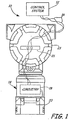
- FIGS. 1 and 2 are diagrammatic and block diagram views of an exemplary wired field device with which embodiments of the present invention are useful.
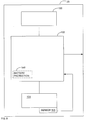
- Process control or monitoring system 10 includes a control room or control system 12 that couples to one or more field devices 14 over a two-wire process control loop 16.
- Examples of process control loop 16 include analog 4-20 mA communication, hybrid protocols which include both analog and digital communication, such as the Highway Addressable Remote Transducer (HART®) standard, as well as all-digital protocols such as the FOUNDATIONTM Fieldbus standard.
- HART® Highway Addressable Remote Transducer
- FOUNDATIONTM Fieldbus all-digital protocols
- process control loop protocols can both power the field device and allow communication between the field device and other devices.
- field device 14 includes circuitry 18 coupled to actuator/transducer 20 and to process control loop 16 via terminal board 21 in housing 23.
- Field device 14 is illustrated as a process variable (PV) generator in that it couples to a process and senses an aspect, such as temperature, pressure, pH, flow, et cetera of the process and provides an indication thereof.
- PV process variable
- Other examples of field devices include valves, actuators, controllers, and displays.
- field devices are characterized by their ability to operate in the "field” which may expose them to environmental stresses, such as temperature, humidity and pressure.
- environmental stresses such as temperature, humidity and pressure.
- field devices must often withstand exposure to corrosive, hazardous and/or even explosive atmospheres. Further, such devices must also operate in the presence of vibration and/or electromagnetic interference.
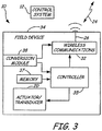
- FIG. 3 is a block diagram of a wireless field device with which embodiments of the present invention are particularly useful.
- Field device 34 includes power conversion module 38, controller 35, wireless communications module 32, and actuator/transducer 20.
- Conversion module 38 can be any device that is able to convert potential energy into electrical energy. Accordingly, conversion module 38 can include a photvoltaic solar panel and associated charging circuit coupled to an energy storage device, such as a battery.
- Conversion module 38 can be any device, known or later developed, that translates potential energy into electricity for use by field device 34. For example, module 38 can employ known techniques to generate electricity from thermal potential energy, wind energy, pressurized gas, or other forms of potential energy. Conversion module 38 can provide power for wireless communications module 32 alone, other portions of field device 34, or may even wholly power field device 34.
- Wireless communications module 32 is coupled to controller 35 and interacts with external wireless devices via antenna 26 based upon commands and/or data from controller 35.
- Wireless communications module 32 can communicate process-related information as well as device-related information.
- wireless communication module 32 may be adapted to communicate in accordance with any suitable wireless communication protocol including, but not limited to: wireless networking technologies (such as IEEE 802.11b wireless access points and wireless networking devices built by Linksys of Irvine, California), cellular or digital networking technologies (such as Microburst® by Aeris Communications Inc.
- GSM Global System for Mobile Communications
- GPRS General Packet Radio Service
- CDMA Code Division Multiple Access
- SMS Short Messaging Service/text messaging
- wireless networking technologies in accordance with IEEE 802.15.4, or any other suitable wireless technology.
- known data collision technology can be employed such that multiple units can coexist within wireless operating rage of one another. Such collision prevention can include using a number of different radio-frequency channels and/or spread spectrum techniques.
- Wireless communications module 32 can also include transceivers for a plurality of wireless communications methods.
- primary wireless communication could be performed using relatively long distance communication methods, such as GSM or GPRS, while a secondary, or additional communication method could be provided for technicians, or operators near the unit, using for example, IEEE 802.11b or Bluetooth.
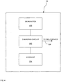
- FIG. 4 is a diagrammatic view of conversion module 38 in accordance with an embodiment of the present invention.
- Conversion module 38 includes electricity generator 100 coupled to charging circuit 102 which, in turn, is coupled to energy storage device 104.
- Charging circuit 102 provides a power output 106 for utilization by a field device.
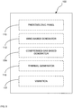
- Generator 100 can include one or more individual generator modules.
- generator 100 can include photovoltaic panel 110, wind-based generator 112, compressed-gas based generator 114, thermal generator 116, vibration-based generator 117, or any combination thereof.
- Conversion module 38 may be embodied within a field device, or disposed externally to a field device and electrically coupled to the field device to provide power to the field device.
- Energy storage device 104 coupled to charging circuit 102, can be any suitable device that is able to store electrical energy for any useable period of time.
- storage device 104 may be a rechargeable battery, such as a gel cell lead-acid battery, or any suitable type of capacitor, such as a super capacitor.
- FIG. 6 is a more detailed block diagram of charging circuit 102 in accordance with an embodiment of the present invention.
- Charging circuit 102 includes a plurality of conductors 120 that couple to generator module 100.
- Charging circuit 102 includes measurement module 122 that is coupled to conductors 120 and is adapted to provide an indication of whether a voltage present across conductors 120 exceeds first and/or second voltage thresholds.
- Measurement circuit 122 can be any suitable device that is able to provide a signal in response to a voltage magnitude measured across conductors 120.
- Measurement module 122 can include an analog-to-digital converter, a comparator circuit, a source of one or more reference potentials, or any combination thereof.
- Measurement module 122 provides for operation of charging circuit 102 in at least three modes.
- measurement circuit 122 sets both outputs 124 and 126 to a low or disengaged state. Accordingly, neither bypass 128 nor cutout 130 are engaged. Accordingly, energy from generator 100 flows through conductors 120 into voltage regulator 132, which provides linear voltage regulation to storage device 104.
- measurement circuit 122 determines that the voltage across conductors 120 has fallen below a first threshold (bypass threshold)
- measurement circuit 122 engages bypass 128 to effectively couple conductors 120 to storage device 104 without passing through voltage regulator 132.
- the entire charging circuit 102 is designed to consume less than 200 microwatts. This provides highly efficient operation in conditions where electrical output from the generator is diminished, such as a solar panel or photovoltaic cell operating in shade.
- measurement circuit 122 When the voltage measured across conductors 120, by measurement circuit 122, falls below a second, lower, threshold (cutout threshold), measurement circuit 122 distinguishes bypass 128 via line 124 and instead engages cutout 130 through line 126 to complexly decouple storage device 104 from the charging circuit. In this mode, for example, when a solar panel is operating at night, circuitry 102 functions to prevent storage device 104 from discharging back through the generator 100.
- FIG. 7 is a diagrammatic view of generator voltage versus time illustrating the various charging circuit modes in accordance with embodiments of the present invention.
- the generator voltage is V initial and since V initial exceeds bypass threshold 140, the charging circuit operates in linear mode. In this mode, the charging circuit provides a regulated voltage output to the storage device.
- the voltage from the generator crosses bypass threshold 140 and charging circuit 102 enters "direct" mode. In this mode, the charging circuit directly couples the generator to the storage device while operating on as little energy as possible. For example, the circuitry of charging circuit 102 is designed to consume less than 200 microwatts of power in this mode.
- the voltage of the generator crosses cutoff threshold 142 and charging circuit 102 enters disconnect mode. In this mode, the storage device is completely decoupled from the generator. This ensures that the storage device does not discharge back through the generator.
- FIG. 8 illustrates energy conversion module 38 in accordance with another embodiment of the present invention.
- storage device 104 is a gel cell lead acid battery. Such batteries can be damaged by overcharging.
- temperature sensor 146 is thermally coupled to battery 104.
- Sensor 146 is electrically coupled to charging circuit 102 such that charging circuit 102 can limit the charge voltage to a safe float value regardless of ambient temperature.
- FIG. 8 also illustrates optional battery protection circuitry 148 (illustrated in phantom) within charging circuit 102. Battery protection circuitry 148 can include any circuitry that helps extend battery life and/or diagnose any faults in battery 104.
- battery life can be reduced if the battery is subjected to short circuits, or if the battery voltage is allowed to drop too low.
- battery protection circuitry 148 can include circuitry that is able to detect when the battery voltage is threatening to drop too low, and will inhibit any further draw of electricity from the battery. Additionally, battery protection circuitry 148 can include current limiting circuitry, or circuitry that is able to measure the amount of current drawn from battery 104 and inhibit, or reduce such current if it becomes excessive.
Description
- In industrial settings, control systems are used to monitor and control inventories of industrial and chemical processes, and the like. Typically, the control system performs these functions using field devices distributed at key locations in the industrial process and coupled to the control circuitry in the control room by a process control loop. The term "field device" refers to any device that performs a function in a distributed control or process monitoring system, including all devices used in the measurement, control and monitoring of industrial processes.
- Field devices are used by the process control and measurement industry for a variety of purposes. Usually, such devices have a field-hardened enclosure so that they can be installed outdoors in relatively rugged environments and are able to withstand climatalogical extremes of temperature, humidity, vibration, mechanical shock, etc. These devices also can typically operate on relatively low power. For example, field devices are currently available that receive all of their operating power from a known 4-20 mA loop.
- Some field devices include a transducer. A transducer is understood to mean either a device that generates an output based on a physical input or that generates a physical output based on an input signal. Typically, a transducer transforms an input into an output having a different form. Types of transducers include various analytical equipment, pressure sensors, thermistors, thermocouples, strain gauges, flow transmitters, positioners, actuators, solenoids, indicator lights, and others.
- Typically, each field device also includes communication circuitry that is used for communicating with a process control room, or other circuitry, over a process control loop. In some installations, the process control loop is also used to deliver a regulated current and/or voltage to the field device for powering the field device.
- Traditionally, analog field devices have been connected to the control room by two-wire process control current loops, with each device connected to the control room by a single two-wire control loop. Typically, a voltage differential is maintained between the two wires within a range of voltages from 12-45 volts for analog mode and 9-50 volts for digital mode. Some analog field devices transmit a signal to the control room by modulating the current running through the current loop to a current proportional to the sensed process variable. Other analog field devices can perform an action under the control of the control room by controlling the magnitude of the current through the loop. In addition to, or in the alternative, the process control loop can carry digital signals used for communication with field devices. Digital communication allows a much larger degree of communication than analog communication. Moreover, digital devices also do not require separate wiring for each field device. Field devices that communicate digitally can respond to and communicate selectively with the control room and/or other field devices. Further, such devices can provide additional signaling such as diagnostics and/or alarms.
- In some installations, wireless technologies have begun to be used to communicate with field devices. Wireless operation simplifies field device wiring and setup. Wireless installations are currently used in which the field device is manufactured to include an internal battery or storage cell that can be potentially charged by a solar cell. One of the challenges for charging circuits that are coupled to photovoltaic solar panels arises due to the widely varying voltage of the panel. At low light levels (less than 5000 lux), small solar panels may only provide 1 to 20 milliwatts. Conversely, under full sun conditions, the same panel may output 1-2 watts. Existing solar charging systems are designed to optimize power output when mounted where they will be illuminated by direct sunlight. If the solar panel must be located in an area which receives no direct sunlight, these existing systems do not operate efficiently and the size and cost of the solar panel must be dramatically increased to generate sufficient power. Providing a charging circuit for wireless field devices that can efficiently store energy from a widely varying energy generator, such as a solar panel, would allow more standardized solar panels or generators to be used for a variety of solar applications.
- Singh P. et al: "Micropower supply for sensors", published in Sensors, 2003, Proceedings of IEEE (Volume: 1), Date of Conference: 22-24 Oct. 2003, pages 600-605 Vol.1 relates to a micropower supply for sensors. It is stated that miniature, remote, autonomous sensors have a relatively large power supply compared to the size of the sensor and sensor conditioning electronic circuitry. An integrated micropower supply made in a silicon wafer offers the prospect of shrinking the power supply size down to the size of the sensor and conditioning circuitry. A micropower supply comprises a nickel-zinc microbattery integrated in a silicon wafer interfaced to a miniature silicon solar array via an adaptable charge controller that can optimally supply charging current from the miniature solar array to the microbattery.
-
US-A-4,383,211 relates to an electrical charging and discharging control apparatus and method, and to a solar to electrical energy conversion apparatus incorporating such control apparatus. -
FR-A-2,689,333 -
DE 201 07 116 U1 relates to an arrangement for providing field devices with electrical energy, the field devices being provided with a wireless communication interface for exchanging data with a central device, wherein the field device is provided with a solar cell. - The present invention provides a charging circuit for field devices and a field device as defined in the claims. The circuit has at least three modes and automatically shifts between the modes depending on voltage of the generator.
- In a first mode, the charging circuit provides voltage regulation. In a second mode, the charging circuit couples the generator directly to an energy storage device. In a third mode, the charging circuit decouples the generator from the storage device. A field device utilizing the charging circuit is also disclosed.
-
FIGS. 1 and2 are diagrammatic and block diagram views of an exemplary field device with which embodiments of the present invention are useful. -
FIG. 3 is a block diagram of a wireless field device with which embodiments on the present invention are useful. -
FIG. 4 is a diagrammatic view of conversion a power module in accordance with an embodiment of the present invention. -
Fig. 5 is a diagrammatic view of a generator showing various options for electricity generation that can be used in accordance with embodiments of the present invention. -
FIG. 6 is a more detailed block diagram of a charging circuit in accordance with an embodiment of the present invention. -
FIG. 7 is a diagrammatic view of generator voltage versus time illustrating the various charging circuit modes in accordance with embodiments of the present invention. -
FIG. 8 illustratesenergy conversion module 38 in accordance with another embodiment of the present invention. - While embodiments of the present invention will generally be described with respect to field devices that communicate wirelessly, those skilled in the art will recognize that embodiments of the present invention can be practiced with any field device that requires additional electricity than that otherwise available to it. A wireless field device may need to derive all of its operating power from a solar panel, or other form of generator, and thus would reap significant benefits from embodiments of the present invention. However, even a wired field device that requires more power than available to it through its wired connection, could derive additional power via embodiments of the present invention.
-
FIGS. 1 and2 are diagrammatic and block diagram views of an exemplary wired field device with which embodiments of the present invention are useful. Process control ormonitoring system 10 includes a control room orcontrol system 12 that couples to one ormore field devices 14 over a two-wireprocess control loop 16. Examples ofprocess control loop 16 include analog 4-20 mA communication, hybrid protocols which include both analog and digital communication, such as the Highway Addressable Remote Transducer (HART®) standard, as well as all-digital protocols such as the FOUNDATION™ Fieldbus standard. Generally, process control loop protocols can both power the field device and allow communication between the field device and other devices. - In this example,
field device 14 includescircuitry 18 coupled to actuator/transducer 20 and to processcontrol loop 16 viaterminal board 21 inhousing 23.Field device 14 is illustrated as a process variable (PV) generator in that it couples to a process and senses an aspect, such as temperature, pressure, pH, flow, et cetera of the process and provides an indication thereof. Other examples of field devices include valves, actuators, controllers, and displays. - Generally, field devices are characterized by their ability to operate in the "field" which may expose them to environmental stresses, such as temperature, humidity and pressure. In addition to environmental stresses, field devices must often withstand exposure to corrosive, hazardous and/or even explosive atmospheres. Further, such devices must also operate in the presence of vibration and/or electromagnetic interference.
-
FIG. 3 is a block diagram of a wireless field device with which embodiments of the present invention are particularly useful.Field device 34 includespower conversion module 38,controller 35,wireless communications module 32, and actuator/transducer 20.Conversion module 38 can be any device that is able to convert potential energy into electrical energy. Accordingly,conversion module 38 can include a photvoltaic solar panel and associated charging circuit coupled to an energy storage device, such as a battery.Conversion module 38 can be any device, known or later developed, that translates potential energy into electricity for use byfield device 34. For example,module 38 can employ known techniques to generate electricity from thermal potential energy, wind energy, pressurized gas, or other forms of potential energy.Conversion module 38 can provide power forwireless communications module 32 alone, other portions offield device 34, or may even whollypower field device 34. -
Wireless communications module 32 is coupled tocontroller 35 and interacts with external wireless devices viaantenna 26 based upon commands and/or data fromcontroller 35.Wireless communications module 32 can communicate process-related information as well as device-related information. Depending upon the application,wireless communication module 32 may be adapted to communicate in accordance with any suitable wireless communication protocol including, but not limited to: wireless networking technologies (such as IEEE 802.11b wireless access points and wireless networking devices built by Linksys of Irvine, California), cellular or digital networking technologies (such as Microburst® by Aeris Communications Inc. of San Jose, California), ultra wide band, free space optics, Global System for Mobile Communications (GSM), General Packet Radio Service (GPRS), Code Division Multiple Access (CDMA), spread spectrum technology, infrared communications techniques, SMS (Short Messaging Service/text messaging), wireless networking technologies in accordance with IEEE 802.15.4, or any other suitable wireless technology. Further, known data collision technology can be employed such that multiple units can coexist within wireless operating rage of one another. Such collision prevention can include using a number of different radio-frequency channels and/or spread spectrum techniques. -
Wireless communications module 32 can also include transceivers for a plurality of wireless communications methods. For example, primary wireless communication could be performed using relatively long distance communication methods, such as GSM or GPRS, while a secondary, or additional communication method could be provided for technicians, or operators near the unit, using for example, IEEE 802.11b or Bluetooth. -
FIG. 4 is a diagrammatic view ofconversion module 38 in accordance with an embodiment of the present invention.Conversion module 38 includeselectricity generator 100 coupled to chargingcircuit 102 which, in turn, is coupled toenergy storage device 104.Charging circuit 102 provides apower output 106 for utilization by a field device.Generator 100, as illustrated inFIG. 5 , can include one or more individual generator modules. For example,generator 100 can includephotovoltaic panel 110, wind-basedgenerator 112, compressed-gas basedgenerator 114,thermal generator 116, vibration-basedgenerator 117, or any combination thereof.Conversion module 38 may be embodied within a field device, or disposed externally to a field device and electrically coupled to the field device to provide power to the field device.Energy storage device 104, coupled to chargingcircuit 102, can be any suitable device that is able to store electrical energy for any useable period of time. For example,storage device 104 may be a rechargeable battery, such as a gel cell lead-acid battery, or any suitable type of capacitor, such as a super capacitor. -
FIG. 6 is a more detailed block diagram of chargingcircuit 102 in accordance with an embodiment of the present invention.Charging circuit 102 includes a plurality ofconductors 120 that couple togenerator module 100.Charging circuit 102 includesmeasurement module 122 that is coupled toconductors 120 and is adapted to provide an indication of whether a voltage present acrossconductors 120 exceeds first and/or second voltage thresholds.Measurement circuit 122 can be any suitable device that is able to provide a signal in response to a voltage magnitude measured acrossconductors 120.Measurement module 122 can include an analog-to-digital converter, a comparator circuit, a source of one or more reference potentials, or any combination thereof.Measurement module 122 provides for operation of chargingcircuit 102 in at least three modes. In a first mode,measurement circuit 122 sets bothoutputs cutout 130 are engaged. Accordingly, energy fromgenerator 100 flows throughconductors 120 intovoltage regulator 132, which provides linear voltage regulation tostorage device 104. Whenmeasurement circuit 122 determines that the voltage acrossconductors 120 has fallen below a first threshold (bypass threshold),measurement circuit 122 engagesbypass 128 to effectively coupleconductors 120 tostorage device 104 without passing throughvoltage regulator 132. In this mode, theentire charging circuit 102 is designed to consume less than 200 microwatts. This provides highly efficient operation in conditions where electrical output from the generator is diminished, such as a solar panel or photovoltaic cell operating in shade. - When the voltage measured across
conductors 120, bymeasurement circuit 122, falls below a second, lower, threshold (cutout threshold),measurement circuit 122 distinguishesbypass 128 vialine 124 and instead engages cutout 130 throughline 126 to complexly decouplestorage device 104 from the charging circuit. In this mode, for example, when a solar panel is operating at night,circuitry 102 functions to preventstorage device 104 from discharging back through thegenerator 100. -
FIG. 7 is a diagrammatic view of generator voltage versus time illustrating the various charging circuit modes in accordance with embodiments of the present invention. At time t0, the generator voltage is Vinitial and since Vinitial exceedsbypass threshold 140, the charging circuit operates in linear mode. In this mode, the charging circuit provides a regulated voltage output to the storage device. At time t1, the voltage from the generator crossesbypass threshold 140 and chargingcircuit 102 enters "direct" mode. In this mode, the charging circuit directly couples the generator to the storage device while operating on as little energy as possible. For example, the circuitry of chargingcircuit 102 is designed to consume less than 200 microwatts of power in this mode. Finally, at time t2, the voltage of the generator crossescutoff threshold 142 and chargingcircuit 102 enters disconnect mode. In this mode, the storage device is completely decoupled from the generator. This ensures that the storage device does not discharge back through the generator. -
FIG. 8 illustratesenergy conversion module 38 in accordance with another embodiment of the present invention. The embodiment illustrated inFIG. 8 is particularly appropriate wherestorage device 104 is a gel cell lead acid battery. Such batteries can be damaged by overcharging. In order to address this potential problem,temperature sensor 146 is thermally coupled tobattery 104.Sensor 146 is electrically coupled to chargingcircuit 102 such that chargingcircuit 102 can limit the charge voltage to a safe float value regardless of ambient temperature.FIG. 8 also illustrates optional battery protection circuitry 148 (illustrated in phantom) within chargingcircuit 102.Battery protection circuitry 148 can include any circuitry that helps extend battery life and/or diagnose any faults inbattery 104. For example, battery life can be reduced if the battery is subjected to short circuits, or if the battery voltage is allowed to drop too low. Accordingly,battery protection circuitry 148 can include circuitry that is able to detect when the battery voltage is threatening to drop too low, and will inhibit any further draw of electricity from the battery. Additionally,battery protection circuitry 148 can include current limiting circuitry, or circuitry that is able to measure the amount of current drawn frombattery 104 and inhibit, or reduce such current if it becomes excessive. - Although the present invention has been described with reference to preferred embodiments, workers skilled in the art will recognize that changes may be made in form and detail without departing from the scope of the invention.
Claims (16)
- A charging system (38) for a field device (14, 34), the charging system comprising:an electrical generator (100) disposed to generate electricity from a source of potential energy;a charging circuit (102) coupled to the generator and disposed to measure a voltage output of the generator;an electrical storage device (104) coupled to the charging circuit (102);wherein the charging circuit (102) includes an output (106) to provide power to the field device (14, 34), and wherein the charging circuit (102) is configured to operate a plurality of modes based upon the voltage output of the generator (100);wherein the charging circuit (102) has a bypass mode wherein the generator (100) is coupled directly to the storage device (104);wherein the charging circuit (102) is in bypass mode when the voltage output of the generator (100) is below the bypass threshold and above a cutout threshold; andwherein the charging circuit (102) has a cutout mode wherein the charging circuit (102) decouples the storage device (104) from the generator by means of a cutout (130) when the voltage output falls below the cutout threshold, to prevent the storage device (104) from discharging back through the generator (100).
- The charging system of claim 1, wherein the charging circuit (102) has a linear mode wherein the charging circuit provides a regulated output to the storage device (104).
- The charging system of claim 2, wherein the charging circuit (102) is in linear mode when the voltage output of the generator (100) is above a bypass threshold.
- The charging system of claim 1, wherein the charging circuit (102) consumes no more than 200 milliwatts in the bypass mode.
- The charging system of claim 1, wherein the charging circuit (102) is in cutout mode when the voltage output of the generator (100) is below a cutout threshold.
- The charging system of claim 1, wherein the generator (100) includes a photovoltaic cell (110) as the source of potential energy.
- The charging system of claim 1, wherein the generator (100) includes at least one of a wind-based generator module (112), a thermal generator module (116), a compressed-gas based generator (114), and a vibration-based generator (117) as the source of potential energy.
- The charging system of claim 1, wherein the electrical storage device (104) is a rechargeable battery.
- The charging system of claim 8, wherein the rechargeable battery is a gel cell lead acid battery.
- The charging system of claim 9, and further comprising a temperature sensor (146) operably coupled to the gel cell lead acid battery and to the charging circuit (102), and wherein the charging circuit limits charging current based upon a temperature of the gel cell lead acid battery.
- The charging system of claim 1, and further comprising battery protection circuitry (148).
- A field device (14, 34) comprising:a transducer (20) operably coupleable to a process;a controller (35) coupled to the transducer;a communications module (32) coupled to the controller (35) and configured to provide process communications functions;an energy conversion module (38) configured to provide electrical energy to the field device, the energy conversion module including the charging system of any of claims 1 to 11.
- The field device of claim 12, wherein the communications module (32) is a wireless communications module.
- The field device of claim 12, wherein the generator (100) includes a photovoltaic cell 110.
- The field device of claim 12, wherein the electrical storage device (104) is a gel cell lead acid battery.
- The field of claim 15, and further comprising a temperature sensor (146) operably coupled to the gel cell lead acid battery and to the charging circuit (102), and wherein the charging circuit limits charging current based upon a temperature of the gel cell lead acid battery.
Applications Claiming Priority (2)
| Application Number | Priority Date | Filing Date | Title |
|---|---|---|---|
| US67564705P | 2005-04-28 | 2005-04-28 | |
| PCT/US2006/016322 WO2006116709A1 (en) | 2005-04-28 | 2006-04-28 | Charging system for field devices |
Publications (2)
| Publication Number | Publication Date |
|---|---|
| EP1875584A1 EP1875584A1 (en) | 2008-01-09 |
| EP1875584B1 true EP1875584B1 (en) | 2020-09-02 |
Family
ID=36809518
Family Applications (1)
| Application Number | Title | Priority Date | Filing Date |
|---|---|---|---|
| EP06751813.4A Active EP1875584B1 (en) | 2005-04-28 | 2006-04-28 | Charging system for field devices |
Country Status (7)
| Country | Link |
|---|---|
| US (1) | US7560907B2 (en) |
| EP (1) | EP1875584B1 (en) |
| JP (1) | JP5328346B2 (en) |
| CN (1) | CN101156294B (en) |
| CA (1) | CA2597145C (en) |
| RU (1) | RU2378753C2 (en) |
| WO (1) | WO2006116709A1 (en) |
Families Citing this family (39)
| Publication number | Priority date | Publication date | Assignee | Title |
|---|---|---|---|---|
| US8538560B2 (en) * | 2004-04-29 | 2013-09-17 | Rosemount Inc. | Wireless power and communication unit for process field devices |
| US8145180B2 (en) | 2004-05-21 | 2012-03-27 | Rosemount Inc. | Power generation for process devices |
| US8112565B2 (en) | 2005-06-08 | 2012-02-07 | Fisher-Rosemount Systems, Inc. | Multi-protocol field device interface with automatic bus detection |
| JP5171939B2 (en) * | 2007-05-02 | 2013-03-27 | ローズマウント インコーポレイテッド | Industrial process field device with improved battery assembly |
| US8264373B2 (en) * | 2008-01-04 | 2012-09-11 | Rosemount Tank Radar Ab | Gauging system having wireless capability |
| US7812466B2 (en) * | 2008-02-06 | 2010-10-12 | Rosemount Inc. | Adjustable resonance frequency vibration power harvester |
| CN102084307B (en) | 2008-06-17 | 2014-10-29 | 罗斯蒙特公司 | RF adapter for field device with low voltage intrinsic safety clamping |
| WO2009154756A1 (en) | 2008-06-17 | 2009-12-23 | Rosemount Inc. | Rf adapter for field device with variable voltage drop |
| US8929948B2 (en) | 2008-06-17 | 2015-01-06 | Rosemount Inc. | Wireless communication adapter for field devices |
| US8694060B2 (en) | 2008-06-17 | 2014-04-08 | Rosemount Inc. | Form factor and electromagnetic interference protection for process device wireless adapters |
| CA2726534C (en) * | 2008-06-17 | 2016-03-22 | Rosemount Inc. | Rf adapter for field device with loop current bypass |
| US8390150B2 (en) * | 2008-07-15 | 2013-03-05 | Fisher-Rosemount Systems, Inc. | Field device interface with network protection mechanism |
| US8467907B2 (en) * | 2009-01-17 | 2013-06-18 | Certus Process Solutions | Automated valve with self-contained valve actuator system |
| US9674976B2 (en) | 2009-06-16 | 2017-06-06 | Rosemount Inc. | Wireless process communication adapter with improved encapsulation |
| US8626087B2 (en) | 2009-06-16 | 2014-01-07 | Rosemount Inc. | Wire harness for field devices used in a hazardous locations |
| US9627903B2 (en) | 2009-07-24 | 2017-04-18 | Robert M. Schwartz | Current sensing circuit disconnect device and method |
| US10050459B2 (en) | 2010-07-26 | 2018-08-14 | Robert M. Schwartz | Current sensing circuit disconnect device and method |
| US10992142B2 (en) | 2010-07-26 | 2021-04-27 | Robert M. Schwartz | Current sensing circuit disconnect device and method |
| US20110095728A1 (en) | 2009-10-28 | 2011-04-28 | Superior Communications, Inc. | Method and apparatus for recharging batteries in a more efficient manner |
| US10761524B2 (en) | 2010-08-12 | 2020-09-01 | Rosemount Inc. | Wireless adapter with process diagnostics |
| DE102011003308B4 (en) | 2011-01-28 | 2014-06-05 | Micropelt Gmbh | Monitoring arrangement and method for monitoring an electrical line |
| JP5408162B2 (en) * | 2011-03-15 | 2014-02-05 | オムロン株式会社 | Charge control device and drive load module |
| DE102011076706A1 (en) * | 2011-05-30 | 2012-12-06 | Endress + Hauser Process Solutions Ag | Electrical and / or electronic power supply circuit and method for providing a supply voltage |
| US9310794B2 (en) | 2011-10-27 | 2016-04-12 | Rosemount Inc. | Power supply for industrial process field device |
| JP5854211B2 (en) * | 2011-12-07 | 2016-02-09 | 横河電機株式会社 | Secondary battery charger |
| KR101882800B1 (en) * | 2012-02-28 | 2018-08-01 | 삼성전자주식회사 | Wireless power receiver and method for controlling thereof |
| WO2014203490A1 (en) * | 2013-06-18 | 2014-12-24 | 三洋電機株式会社 | Power feeding apparatus for solar cell, and solar cell system |
| US20150008867A1 (en) * | 2013-07-03 | 2015-01-08 | At&T Intellectual Property I, L.P. | Charge pump battery charging |
| US9601938B2 (en) * | 2014-05-15 | 2017-03-21 | Intel Corporation | Battery charger for different power sources |
| DE102014011723B4 (en) * | 2014-08-06 | 2017-11-23 | Abb Schweiz Ag | Device for the intrinsically safe, redundant power supply of field devices |
| WO2016098802A1 (en) * | 2014-12-18 | 2016-06-23 | 株式会社フジクラ | Electrical storage system, and electrical storage method |
| US10333339B2 (en) * | 2016-04-12 | 2019-06-25 | Rai Strategic Holdings, Inc. | Charger for an aerosol delivery device |
| CN107024270B (en) * | 2016-12-05 | 2019-08-23 | 陈山鹏 | Radio detection, the method for diagnosing building or equipment status parameter |
| RU2711962C1 (en) * | 2018-10-03 | 2020-01-23 | Алексей Федорович Хорошев | Electronic calculation providing device, electronic calculation optimizing device and such electronic calculation method |
| RU2711950C1 (en) * | 2018-10-03 | 2020-01-23 | Алексей Федорович Хорошев | Crypto currency mining providing device, crypto currency mining optimizing device and method of such crypto currency mining |
| US11476685B2 (en) | 2019-09-09 | 2022-10-18 | General Electric Company | System and method for detecting battery faults in a pitch system of a wind turbine |
| US11855470B2 (en) * | 2021-09-23 | 2023-12-26 | Fluidity Power LLC | Mobile generator charging system and method |
| CN114294065B (en) * | 2021-12-30 | 2024-02-27 | 中控技术股份有限公司 | Pneumatic explosion-proof power supply device and implementation method thereof |
| DE102022120434A1 (en) * | 2022-08-12 | 2024-02-15 | Vega Grieshaber Kg | Method for charging an energy storage device of a field device and field device for carrying out the method |
Citations (1)
| Publication number | Priority date | Publication date | Assignee | Title |
|---|---|---|---|---|
| JPH1146457A (en) * | 1997-07-25 | 1999-02-16 | Tdk Corp | Charging device utilizing solar cell |
Family Cites Families (60)
| Publication number | Priority date | Publication date | Assignee | Title |
|---|---|---|---|---|
| US1392096A (en) * | 1920-01-10 | 1921-09-27 | Nicholas J Wagner | Roof-truss |
| US2976473A (en) * | 1959-06-17 | 1961-03-21 | Crane Co | Voltage regulator for generators |
| US3911350A (en) * | 1973-04-09 | 1975-10-07 | Union Carbide Corp | Dual battery charging rate device |
| US4233553A (en) * | 1978-05-10 | 1980-11-11 | Ault, Inc. | Automatic dual mode battery charger |
| JPS5537881A (en) * | 1978-09-08 | 1980-03-17 | Nippon Denso Co | Automotive generator voltage controller |
| FR2438934A1 (en) * | 1978-10-09 | 1980-05-09 | Accumulateurs Fixes | DEVICE FOR REGULATING THE CHARGE OF A BATTERY |
| US4315163A (en) * | 1980-09-16 | 1982-02-09 | Frank Bienville | Multipower electrical system for supplying electrical energy to a house or the like |
| US4383211A (en) * | 1981-01-02 | 1983-05-10 | Atlantic Richfield Company | Electrical charging and discharging control apparatus and method, and solar to electrical energy conversion apparatus incorporating such apparatus |
| US4433277A (en) * | 1982-06-21 | 1984-02-21 | Rockwell International Corporation | Battery charging system |
| US4636706A (en) * | 1985-09-12 | 1987-01-13 | General Motors Corporation | Generator voltage regulating system |
| US5028859A (en) * | 1989-06-05 | 1991-07-02 | Motorola, Inc. | Multiple battery, multiple rate battery charger |
| US5121047A (en) * | 1990-06-01 | 1992-06-09 | Motorola, Inc. | Battery charging system |
| US5229705A (en) * | 1990-07-31 | 1993-07-20 | Nippon Densan Corporation | Method and apparatus for charging a nickel-cadmium battery |
| US5166595A (en) * | 1990-09-17 | 1992-11-24 | Circom Inc. | Switch mode battery charging system |
| US5304917A (en) * | 1990-11-30 | 1994-04-19 | Burr-Brown Corporation | Compact low noise low power dual mode battery charging circuit |
| US5111131A (en) * | 1990-11-30 | 1992-05-05 | Burr-Brown Corporation | Compact low noise low power dual mode battery charging circuit |
| US5122722A (en) * | 1991-01-17 | 1992-06-16 | Motorola, Inc. | Battery charging system |
| US5198698A (en) * | 1991-02-11 | 1993-03-30 | Best Power Technology, Inc. | Auxiliary power supply system for providing dc power on demand |
| US5270636A (en) * | 1992-02-18 | 1993-12-14 | Lafferty Donald L | Regulating control circuit for photovoltaic source employing switches, energy storage, and pulse width modulation controller |
| FR2689333B1 (en) | 1992-03-30 | 1995-02-24 | Transenergie | Regulator and recorder assembly for electrical energy production and storage installation. |
| US5311112A (en) * | 1993-02-26 | 1994-05-10 | Kussmaul Electronics Company Inc. | Automatic battery charging system |
| US5535243A (en) * | 1994-07-13 | 1996-07-09 | Rosemount Inc. | Power supply for field mounted transmitter |
| US5710506A (en) * | 1995-02-07 | 1998-01-20 | Benchmarq Microelectronics, Inc. | Lead acid charger |
| KR0163571B1 (en) * | 1995-10-30 | 1999-04-15 | 김광호 | Dual battery charging apparatus |
| US6495992B1 (en) * | 1996-03-26 | 2002-12-17 | Norvik Traction Inc. | Method and apparatus for charging batteries utilizing heterogeneous reaction kinetics |
| JP3428820B2 (en) * | 1996-06-11 | 2003-07-22 | キヤノン株式会社 | Charging device |
| US5929538A (en) * | 1997-06-27 | 1999-07-27 | Abacus Controls Inc. | Multimode power processor |
| US5955867A (en) * | 1997-07-29 | 1999-09-21 | Dell Usa L.P. | Dual battery pack charging in a computer system |
| US5949216A (en) * | 1997-08-27 | 1999-09-07 | Ericsson Inc. | Dual mode battery chargers for portable electronic devices and related methods |
| US6057666A (en) * | 1997-09-17 | 2000-05-02 | Johnson Controls Technology Company | Method and circuit for controlling charging in a dual battery electrical system |
| US6979507B2 (en) * | 2000-07-26 | 2005-12-27 | Idatech, Llc | Fuel cell system controller |
| US6194877B1 (en) * | 1999-08-02 | 2001-02-27 | Visteon Global Technologies, Inc. | Fault detection in a motor vehicle charging system |
| DE60029617D1 (en) * | 1999-12-02 | 2006-09-07 | Snap On Tools Corp | CHARGING CONSERVATION SYSTEM OF A LEAD ACID BATTERY |
| US6835481B2 (en) * | 2000-03-29 | 2004-12-28 | Idatech, Llc | Fuel cell system with load management |
| DE10015619A1 (en) * | 2000-03-29 | 2001-10-04 | Endress Hauser Gmbh Co | Programmable field device |
| US6515456B1 (en) * | 2000-04-13 | 2003-02-04 | Mixon, Inc. | Battery charger apparatus |
| US6353306B1 (en) * | 2000-04-13 | 2002-03-05 | Mixon, Inc. | Battery charger apparatus |
| JP2002062942A (en) * | 2000-08-22 | 2002-02-28 | Sanyo Electric Industries Co Ltd | Control device for independent power source by wind power generator |
| US6476509B1 (en) * | 2001-04-19 | 2002-11-05 | Unit Parts Company | Mobile AC power system |
| DE20107116U1 (en) * | 2001-04-25 | 2001-07-05 | Abb Patent Gmbh | Device for supplying energy to field devices |
| US6414465B1 (en) * | 2001-06-22 | 2002-07-02 | France/Scott Fetzer Company | Method and apparatus for charging a lead acid battery |
| US6877948B2 (en) * | 2001-07-10 | 2005-04-12 | Alan B. Cutcher | Wind turbine generator |
| US6690140B2 (en) * | 2001-08-30 | 2004-02-10 | International Truck Intellectual Property Company, Llc | Vehicle electrical system |
| US20030057919A1 (en) * | 2001-09-27 | 2003-03-27 | Tai-Her Yang | Storage/discharging device charging circuit of multi-differential source |
| JP2003111301A (en) * | 2001-09-28 | 2003-04-11 | Sanyo Electric Co Ltd | Power unit for solar battery |
| US6707278B2 (en) * | 2002-04-22 | 2004-03-16 | Delphi Technologies, Inc. | Transition voltage start regulator |
| US6885233B2 (en) * | 2002-05-02 | 2005-04-26 | Intel Corporation | Altering operating frequency and voltage set point of a circuit in response to the operating temperature and instantaneous operating voltage of the circuit |
| US20030224833A1 (en) * | 2002-05-29 | 2003-12-04 | Thomas Egan | Cellular base station power generator having remote monitoring and control |
| JP3926699B2 (en) * | 2002-07-30 | 2007-06-06 | 株式会社リコー | Secondary battery charging device and charging method thereof |
| US6930402B1 (en) * | 2003-05-15 | 2005-08-16 | Sprint Communications Company L.P. | Power system for a telecommunication facility |
| US7245032B2 (en) * | 2002-11-15 | 2007-07-17 | Sprint Communications Company L.P. | Mobile-power system utilizing propane generator, fuel cell and super capacitors |
| US6888337B2 (en) * | 2003-03-04 | 2005-05-03 | Hewlett-Packard Development Company, L.P. | Power system and method |
| JP2004280449A (en) * | 2003-03-14 | 2004-10-07 | Toshiba Corp | Data measurement device |
| JP4355160B2 (en) * | 2003-04-16 | 2009-10-28 | 理研計器株式会社 | Gas detector |
| US7250231B2 (en) * | 2003-06-09 | 2007-07-31 | Idatech, Llc | Auxiliary fuel cell system |
| US6975043B2 (en) * | 2003-12-22 | 2005-12-13 | Rosemount, Inc. | Pressurized gas to electrical energy conversion for low-power field devices |
| US7116079B2 (en) * | 2004-02-27 | 2006-10-03 | Research In Motion Limited | Methods and apparatus for simultaneously charging multiple rechargable batteries |
| US8538560B2 (en) * | 2004-04-29 | 2013-09-17 | Rosemount Inc. | Wireless power and communication unit for process field devices |
| US7081687B2 (en) * | 2004-07-22 | 2006-07-25 | Sprint Communications Company L.P. | Power system for a telecommunications facility |
| US7274975B2 (en) * | 2005-06-06 | 2007-09-25 | Gridpoint, Inc. | Optimized energy management system |
-
2006
- 2006-04-28 EP EP06751813.4A patent/EP1875584B1/en active Active
- 2006-04-28 CN CN2006800109258A patent/CN101156294B/en active Active
- 2006-04-28 WO PCT/US2006/016322 patent/WO2006116709A1/en active Application Filing
- 2006-04-28 JP JP2008509182A patent/JP5328346B2/en not_active Expired - Fee Related
- 2006-04-28 RU RU2007144064A patent/RU2378753C2/en not_active IP Right Cessation
- 2006-04-28 US US11/414,491 patent/US7560907B2/en active Active
- 2006-04-28 CA CA 2597145 patent/CA2597145C/en not_active Expired - Fee Related
Patent Citations (1)
| Publication number | Priority date | Publication date | Assignee | Title |
|---|---|---|---|---|
| JPH1146457A (en) * | 1997-07-25 | 1999-02-16 | Tdk Corp | Charging device utilizing solar cell |
Also Published As
| Publication number | Publication date |
|---|---|
| CA2597145A1 (en) | 2006-11-02 |
| JP2008539561A (en) | 2008-11-13 |
| US7560907B2 (en) | 2009-07-14 |
| RU2378753C2 (en) | 2010-01-10 |
| EP1875584A1 (en) | 2008-01-09 |
| RU2007144064A (en) | 2009-06-10 |
| CN101156294A (en) | 2008-04-02 |
| US20060244424A1 (en) | 2006-11-02 |
| WO2006116709A1 (en) | 2006-11-02 |
| CA2597145C (en) | 2015-03-03 |
| JP5328346B2 (en) | 2013-10-30 |
| CN101156294B (en) | 2010-12-29 |
Similar Documents
| Publication | Publication Date | Title |
|---|---|---|
| EP1875584B1 (en) | Charging system for field devices | |
| EP1749250B1 (en) | Power and wireless communication unit for process field devices | |
| EP1721067B1 (en) | Process device with improved power generation | |
| EP1929386B1 (en) | Improved power generation for process devices | |
| RU2389056C2 (en) | Field device with radio-frequency connection, in which consumed power is controlled dynamically | |
| JP5827755B2 (en) | Process control field device with circuit protection | |
| US11742676B2 (en) | Actuating mechanism with integral battery |
Legal Events
| Date | Code | Title | Description |
|---|---|---|---|
| PUAI | Public reference made under article 153(3) epc to a published international application that has entered the european phase |
Free format text: ORIGINAL CODE: 0009012 |
|
| 17P | Request for examination filed |
Effective date: 20071031 |
|
| AK | Designated contracting states |
Kind code of ref document: A1 Designated state(s): CH DE LI |
|
| RBV | Designated contracting states (corrected) |
Designated state(s): CH DE LI |
|
| DAX | Request for extension of the european patent (deleted) | ||
| 17Q | First examination report despatched |
Effective date: 20130208 |
|
| RAP1 | Party data changed (applicant data changed or rights of an application transferred) |
Owner name: ROSEMOUNT INC. |
|
| STAA | Information on the status of an ep patent application or granted ep patent |
Free format text: STATUS: EXAMINATION IS IN PROGRESS |
|
| REG | Reference to a national code |
Ref country code: DE Ref legal event code: R079 Ref document number: 602006059641 Country of ref document: DE Free format text: PREVIOUS MAIN CLASS: H02J0007350000 Ipc: H02J0007340000 |
|
| RIC1 | Information provided on ipc code assigned before grant |
Ipc: H02J 7/35 20060101ALI20200313BHEP Ipc: H02J 15/00 20060101ALI20200313BHEP Ipc: H02J 7/34 20060101AFI20200313BHEP |
|
| GRAP | Despatch of communication of intention to grant a patent |
Free format text: ORIGINAL CODE: EPIDOSNIGR1 |
|
| STAA | Information on the status of an ep patent application or granted ep patent |
Free format text: STATUS: GRANT OF PATENT IS INTENDED |
|
| INTG | Intention to grant announced |
Effective date: 20200428 |
|
| GRAS | Grant fee paid |
Free format text: ORIGINAL CODE: EPIDOSNIGR3 |
|
| GRAA | (expected) grant |
Free format text: ORIGINAL CODE: 0009210 |
|
| STAA | Information on the status of an ep patent application or granted ep patent |
Free format text: STATUS: THE PATENT HAS BEEN GRANTED |
|
| AK | Designated contracting states |
Kind code of ref document: B1 Designated state(s): CH DE LI |
|
| REG | Reference to a national code |
Ref country code: CH Ref legal event code: EP |
|
| REG | Reference to a national code |
Ref country code: DE Ref legal event code: R096 Ref document number: 602006059641 Country of ref document: DE |
|
| REG | Reference to a national code |
Ref country code: CH Ref legal event code: NV Representative=s name: VOSSIUS AND PARTNER PATENTANWAELTE RECHTSANWAE, CH |
|
| REG | Reference to a national code |
Ref country code: DE Ref legal event code: R097 Ref document number: 602006059641 Country of ref document: DE |
|
| PLBE | No opposition filed within time limit |
Free format text: ORIGINAL CODE: 0009261 |
|
| STAA | Information on the status of an ep patent application or granted ep patent |
Free format text: STATUS: NO OPPOSITION FILED WITHIN TIME LIMIT |
|
| 26N | No opposition filed |
Effective date: 20210603 |
|
| PG25 | Lapsed in a contracting state [announced via postgrant information from national office to epo] |
Ref country code: LI Free format text: LAPSE BECAUSE OF NON-PAYMENT OF DUE FEES Effective date: 20210430 Ref country code: CH Free format text: LAPSE BECAUSE OF NON-PAYMENT OF DUE FEES Effective date: 20210430 |
|
| PGFP | Annual fee paid to national office [announced via postgrant information from national office to epo] |
Ref country code: DE Payment date: 20230321 Year of fee payment: 18 |